1
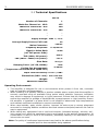
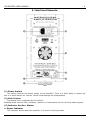
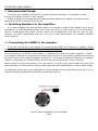
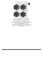
1 GM SERIES USER MANUAL CONTENTS: Page Thank You Congratulations on the purchase of your new Matrix Professional Power Amplifier. Matrix amplifiers are the result of many decades of experience in the design of exceptionally robust and reliable amplifiers. They are designed to breathe life into your sound, by controlling your speakers with exacting authority through the uncompromising delivery of clean, undistorted power, from a package which is smaller and lighter than you might expect for the performance it delivers. This manual will help you to get the most from your amplifier. For maximum benefit, it is recommended that all instructions and warnings are carefully read. Also be sure to read the notices regarding correct wiring of output connectors as this impacts the operation of the amplifier. For warranty service, please retain your receipt and all packaging that comes with the amplifier, as it has been specifically designed to transport the amplifier safely. Unpacking Thank You 1 1. Features and Innovations 2 2. Specifications 3 2.1 Technical specifications 3. Interface Elements 4-5 3.1 Front Panel 4. Recommended Usage 6 6. Trouble Shooting 7 7. Warranty 8 8. Declaration of CE Conformity 9 CAUTION: OBSERVE ALL SAFETY AND USAGE INSTRUCTIONS TO AVOID POSSIBLE DAMAGE TO EQUIPMENT AND EXPOSURE TO HAZARDS (THIS SYMBOL UNIVERSALLY FLAGS CAUTION NOTICES) Please unpack and inspect your new amplifier for any damage that may have occurred during transit. If damage is found, notify the carrier immediately. Note: A suitable mains lead is provided and can be found packaged with the amplifier. PLEASE RETAIN ALL FACTORY PACKAGING FOR ANY FUTURE POSTAL TRANSIT. LETHAL VOLTAGES PRESENT AT SPEAKER TERMINALS AND INSIDE THE AMPLIFIER; ENSURE ALL WIRING IS SAFE AND CORRECT BEFORE USE. (THIS SYMBOL ALSO UNIVERSALLY FLAGS ELECTRICAL HAZARDS) DO NOT OPEN THE AMPLIFIER; LEAVE ALL INTERNAL SERVICE OPPERATIONS TO A QUALIFIED TECHNICIAN. GM SERIES USER MANUAL 2 1. Features and Innovations All our amplifiers have been designed to give the best possible performance for their intended application and are based on our own uncompromising, time proven MOSFET designs. These take advantage of components which will stand the test of time and give the best possible performance in a small, exceptionally light weight package. We only have the desire to provide our users with the best possible solutions and continue to look for ways to improve upon them. Amplifier features: Design Optimised for Guitar Amplification. Class AB, MOSFET amplifier topology. .. An unprecedentedly powerful and stable Switch Mode Power Supply. Designed without compromise, to exceed the performance of the previous linear supply models; whilst offering a weight advantage rarely seen even in other SMPS amplifiers. . Soft Start Circuit. The power supply is designed not to draw excessive current on startup - Prevents the 'thump' as occasionally occurs with other equipment, from tripping fuses and breakers. . Protection against Short Circuit and Overheating. . Speaker Protection relay with delay to inhibit switch on thump. The speakers are disconnected during power up/down. Fully balanced XLR Inputs, which also accept 1/4” jack connectors.. . Flying lead Output connection For direct connections to drivers when installed in a loudspeaker cabinet. . Temperature regulated, High Speed Fan Cooling. A high speed fan is utilised to ensure maximum reliability by allowing for far greater cooling latitude (The amplifier vents hot air through rear connector panel). . 0.775v / 0 dBu Inputs. Input level optimised for guitar modellers and pre-amplifiers. . Cabinet Instillation Module Case Format. A compact amplifier case designed for installation directly into speaker cabinets. Note: This equipment has been tested and found to comply with the limits for a Class B digital device, pursuant to part 15 of the FCC Rules. These limits are designed to provide reasonable protection against harmful interference in a residential installation. This equipment generates, uses and can radiate radio frequency energy and, if not installed and used in accordance with the instructions, may cause harmful interference to radio communications. However, there is no guarantee that interference will not occur in a particular installation. If this equipment does cause harmful interference to radio or television reception, which can be determined by turning the equipment off and on, the user is encouraged to try to correct the interference by one or more of the following measures: — — — — Reorient or relocate the receiving antenna. Increase the separation between the equipment and receiver. Connect the equipment into an outlet on a circuit different from that to which the receiver is connected. Consult the dealer or an experienced radio/TV technician for help. 3 GM SERIES USER MANUAL 2.1 Technical Specifications GM 50 Number of Channels: 1 Watts Per Channel at - 16 Ω: 125 Watts Per Channel at - 8 Ω: 250 Watts Per Channel at - 4 Ω: 400 - - - - Supply Voltage: 230V +/- 15% Average Supply Current, Full Load: 4A Mains Connector: 10A IEC Frequency Response: 8–24,000 Hz Signal to Noise Ratio (ref. Full power 1kHz): 96 dB THD (1kHz, full power): 0.06% THD (20Hz - 20kHz, full power): <0.1% Slew Rate: 50 V/µs Damping Factor (ref. 8R, 100Hz): >400 Cooling Fan Arrangement: (Temperature controlled dual speed fans) 2x 40mm Input Level Sensitivity: 0.775v / 0 dBu Dimensions (LWH - mm): 312 X 160 X 65 Weight: 2.43 Kg Additional Features: - Operating Environment: ● ● ● ● The amplifier is designed for use in environments which protect it from rain, unusually high air humidity and temperature. When installing in a speaker cabinet or another suitable space, ensure that the amplifier is securely mounted using all available fixing points where possible. Improper instillation may result in damage to equipment or injure personnel. Ensure that the location will not expose the amplifier to spillage of liquids/drinks, sprays/vapours or high humidity. Ensure the amplifier is installed in a place which is not subject to abnormally high temperatures and maintain sufficient ventilation to prevent overheating. When used outside, apply similar caution; however be extra sure to ensure placement accounts for changing weather conditions and that extreme wind/rain/heat will not find its way to equipment. When taking any equipment from a cold environment (unheated storage, vehicles, etc), into a warm one, allow the equipment time to acclimatise to the ambient temperature, as condensation is likely to form in the amplifier, potentially causing it to malfunction if put into service too soon. Note: Our policy of continuous improvement may lead to the above specifications being exceeded prior to documentation being updated. GM SERIES USER MANUAL 4 . 3. Interface Elements. .. (1) Power Switch This switch controls the power supply to the amplifier. There is a short delay on power-up, this is to avoid switch-on "thump" which could damage the loudspeakers. . (2) Gain Control The Output level is adjusted by this control. Rotating these controls fully clockwise, results in no attenuation to the incoming audio signals. . (3) Indicator Section, Status: a. Power Indicator This indicator shows when the amplifier is on and is receiving power. 5 GM SERIES USER MANUAL (4) Cooling Fan Outlet Hot air exits here. Make sure all ventilation paths & slots are free from obstruction and air flows freely, otherwise the amplifier will trip into thermal protect mode prematurely and in some extreme circumstances damage may occur. (5) Output Connectors . The Output connections to speakers are made via the flying leads. Take precautions to ensure wires do not short, as this is may damage the amplifier. Additionally do not operate this amplifier in any manner which may lead to users coming into contact with the amplifier output terminals, Lethal Voltages maybe present & injury may occur. (6) Input Signal Sockets . These are combined female XLR and 1/4" jack sockets. They provide a number of connection possibilities, including the industry standard Balanced XLR system, which helps ensure interference and noise free connections between equipment. Ready-made, sensibly priced, quality interconnection leads suitable for use with the amplifier should be easy to source. (7) Power Connection . Mains power is supplied to the amplifier by a standard 10 Amp IEC mains socket. An appropriate mains lead is supplied with the amplifier. Fuse change for amplifier is also available here. Note: The amplifier requires a stable power supply to function as intended. Ensure that the power source (mains power supply, generator, etc.) is suitable for this application and adequate power is available. Poorly selected power sources result in sub-optimal performance, increased likelihood of tripping breakers, blowing fuses and in extreme situations damage to equipment may occur. Should the fuse in the mains lead blow for any reason, it must be replaced with a fuse of the correct rating. This should be 13 amps for the models listed in this manual. However, if there is any reason to believe that a malfunction caused the fuse to blow, stop using the equipment immediately and take the amplifier to an authorised service engineer for servicing. GM SERIES USER MANUAL 6 4. Recommended Usage: To ensure your speaker and amplifier system functions optimally, it is advised to read through everything covered in this manual. Safety precautions and appropriate usage recommendations for specific connections and features are noted in the previous section. . 4.1 Matching Speakers to the amplifier: . It is recommended that the amplifier power is matched to that of the speaker at its given impedance (or total impedance where more than one driver is used, such as in a 4 driver cab). Various combinations that don't strictly match this arrangement may well be safe to use, however we would recommend that you only do so under advisement of a suitably qualified audio engineer. 4.2 Connecting the GM50 to the speaker: If you are unsure as to any aspect of connecting the GM50 to a cabinet or speaker please seek the help or guidance of a qualified or competent engineer. The red wire from the GM50 is the positive (+) feed and the black wire is the negative (-) feed. The simplest method of connecting is to attach the red wire to the positive speaker terminal and the black wire to the negative speaker terminal or in the case of systems featuring a crossover network, connecting the corresponding wires to the correct terminals on the crossover. When using more than one speaker (such as a 2x12, or 4x12) care must be taken to ensure the total impedance of the speakers does not fall below the rated specifications of the module (4 Ω). The diagrams below give some examples of typical speaker wiring methods but this list is by no means exhaustive and further methods may be found online. Wiring your speaker like this will give you the same impedance as the speaker used. Wiring your speakers in parallel like this will give you the following impedances: 2 x 4 ohm speakers = 2 ohm load (Not Suitable) 2 x 8 ohm speakers = 4 ohm load 2 x 16 ohm speakers = 8 ohm load You may also use a combination of different value Speakers as long as their total is no less than 4 ohm Wiring your speakers in series like this will give you the following impedances: 2 x 4 ohm speakers = 8 ohm load 2 x 8 ohm speakers = 16 ohm load 2 x 16 ohm speakers = 32 ohm load (Not Recommended) Using this series/parallel wiring, the total impedance of your cabinet will be the same as an individual speaker (only if all speakers are the same impedance). So if you are using x4 4 ohm speakers, the cabinet will be 4 ohms. If using x4 8 ohm speakers, the cabinet will be 8 ohms, etc. 9 GM SERIES USER MANUAL 6. TROUBLE SHOOTING. . . (1) ALWAYS: ● Ensure the amplifier has no less than 4 Ohms worth of loading across the output channel. ● Ensure wiring is safe and correct. . (2) NORMAL ARTIFACTS: ● When heavily driven, the amplifier itself may make a noticeable hissing sound in relation to the supplied signal. This is a normal phenomenon relating to the behaviour of certain components which vibrate slightly under the high powers involved. . (3) THE POWER LIGHT DOES NOT ILLUMINATE 1. 2. 3. 4. (same 5. 6. . Check that the mains supply is turned on. Check that the mains switch is turned on. Check Mains lead for damage & check fuse. Replace lead if damaged, replace fuse if blown. Check external fuse (found in the amplifiers power inlet section). Replace if blown. type of fuse specified/installed must be used, do not change) If fuse re-blows refer to service personnel. If fuse has not blown, but the amplifier still malfunctions, refer to service personnel. (4) THE AMPLIFIER IS WORKING, BUT OUTPUT VOLUME IS LOW . ● . Check the signal from the input source and signal cables. The amplifiers are designed to operate at an input voltage of 0.775V. If the intended signal source is above this, refer to qualified service personnel for a minor modification. (5) AMP OUTPUT LEVEL INDICATORS ARE WORKING, BUT NO SOUND IS COMING OUT . ● . Check that amplifier is correctly and securely connected to the cabinet's loudspeakers (6) THE AMPLIFIER IS GIVING A LOWER OUTPUT THAN NORMAL, WITH DISTORTION . ● . The protection circuits (current clamps) are operating. Check all leads for short-circuits. Try another set of leads and loudspeakers. (7) THE AMPLIFIER IS OVERHEATING . ● ● Check that the fan is not obstructed with debris, and is rotating freely. Check speaker leads for short circuits. . If any of these, or other symptoms persist, Please contact us with the details below for help, advice and service: Contact Details: Email: [email protected] Address: MATRIX AMPLIFICATION LIMITED, Unit 1b, Techways, Wonastow Road Industrial Estate, Monmouth, Wales, NP25 5JA. If the amplifier is to be shipped, use factory packaging or other secure method as transit damage is not covered by the warranty. GM SERIES USER MANUAL 10 Full Two Year Warranty Summary of Warranty . Matrix Amplification Limited, warrant to you, the ORIGINAL PURCHASER of each Matrix Power Amplifier, for a period of 2 (two) years from the date of purchase, that the amplifier is free from defects in materials and workmanship and we further warrant the new Matrix Amplifier, regardless of the reason of failure except as excluded in this warranty. Items Subject to Exclusion from this Warranty . This Matrix Amplifier Warranty is in effect only for failure of a new Matrix Amplifier which occurred during the warranty period. It does not cover any product that has been damaged because of any misuse be it intentional or otherwise, accident, negligence, or loss which is covered under any insurance. What the Warranter Will Do . We will remedy any defect, regardless of the reason for failure (except as excluded above), by repair or replacement. Warranty work can only be performed at our authorised distributors or at Matrix Amplification Limited. We will remedy the defect and ship the product from the service centre or our own factory within a reasonable time after receipt of the defective product. All expenses in remedying the defect, including freight costs from ourselves to you (within mainland UK) will be borne by us. You must bear the costs of shipping the product to our authorised service centre or factory. How to Obtain Warranty Service . You must notify us of your need for warranty service not later than the expiry of your warranty. The amplifier must be shipped in a factory pack, which if required can be obtained from us at a modest charge. The amplifier must be sent to us carriage paid and insured. Corrective action will be taken within a reasonable time from the date of receipt of the defective product by us or our authorised service center. If repairs made by us or our authorised service center are not satisfactory, contact us immediately. Warranty Alterations .. No person has the authority to enlarge, amend or modify this warranty. The warranty is not extended by the length of time which you are deprived of the use of the amplifier. Repairs and replacement parts will only carry the unexpired portion of this warranty. Design Changes . Matrix Amplification Limited has a policy of continuous improvement to designs without notice and with no obligation to make corresponding changes in products previously manufactured. Your Statutory Rights are Unaffected by this Warranty 11 GM SERIES USER MANUAL Declaration of CE Conformity . Issuers Name and Address: Andrew Hunt, MATRIX AMPLIFICATION LIMITED, Cordes House, Factory Road, Newport, Gwent, United Kingdom. NP20 5FA Products: GM50/GM100 Equipment Type: Commercial Audio Power Amplifiers. Safety Standard: AMD1: 2005 and IEC 60065: 2001 7th Ed. Safety Requirements - Audio Video and Similar Electronic Apparatus. EMC Standards: EN 61000-4-2:2001 Electrostatic Discharge Immunity (Environment E2-Criteria B, 4k V Contact, 8k V Air Discharge). EN 61000-4-3:2006 Radiated, Radio-Frequency, Electromagnetic Immunity (Environment E2, criteria A). EN 61000-4-4:2007 Electrical Fast Transient/Burst Immunity (Criteria B). EN 61000-4-5:2006 Surge Immunity (Criteria B). EN 61000-4-6:2006 Immunity to Conducted Disturbances Induced by Radio-Frequency Fields (Criteria A). EN 61000-4-11:2001 Voltage Dips, Short Interruptions and Voltage Variation. EN 55103-1:1997 Electromagnetic Compatibility - Product Family Standard for Audio, Video, Audio-Visual and Entertainment Lighting Control Apparatus for Professional Use, Part 1: Emissions. EN 55103-1:1997 Magnetic Field Emissions-Annex A @ 10 cm and 20 cm. EN 55103-2:1997 Electromagnetic Compatibility - Product Family Standard for Audio, Video, Audio-Visual and Entertainment Lighting Control Apparatus for Professional Use, Part 2: Immunity. EN 61000-3-2:2005 and AMD1: 2008 Limits for Harmonic Current Emissions (equipment input current less than or equal to 16 A per phase). EN 55022:2006 Limits and Methods of Measurement of Radio Disturbance Characteristics of ITE: Radiated, Class B Limits; Conducted, Class A. EN 61000-3-3:2008 Limitation of Voltage Fluctuations and Flicker in Low-Voltage Supply Systems Rated Current less than or equal to 16A. Declaration: I certify that the product identified above conforms to the requirements of the EMC Council Directive 89/336/EEC as amended by 92/31/EEC, and the Low Voltage Directive 73/23/EES as amended by 93/68/EEC. Signatories: Andrew Hunt, Managing Director. Date of Issue: 2 April 2012.