1
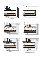
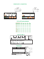
Via Vizzano 44 - 40037 Pontecchio Marconi (Bologna)Italy Tel. +39 051 6782006 - Fax +39 051 845544 http://www.elcontrol-energy.net e-mail: Italia [email protected] estero: [email protected] ENGLISH DMM3 Multi Panel Meter USER MANUAL WARNING Elcontrol Energy Net S.p.a. declines all liability for any damage to people or property caused by unsuitable or incorrect use of its products. Elcontrol Energy Net reserves the right to change product specifications without prior notice. 3YYYB113 DMM3_User Maunual Eng Rev. 02/2005 MEASURES PAGES L1 L2 L1 L3 L2 L3 V A Fig. 1 VL1, VL2, VL3 (three-phase only) L1 L2 Fig. 2 AL1, AL2, AL3 (three-phase only) L1 L3 Fig. 4 P1, P2, P3(three-phase only) Fig. 3 A neutral (three-phase only) L2 L1 L3 L2 Fig. 6 Q1, Q2, Q3(three-phase only) Fig. 5 S1, S2, S3 (three-phase only) L2 L1 L3 Fig. 7 P.F.1,P.F.2,P.F.3, (three-phase only) 3F L2 kW L2 PF Fig. 8 V, A, Hz(three and single-phase only) L2 L2 h Fig. 10 kWh Tot kVar Fig. 11 kvarh Tot L1 L3 L3 kW kVA Fig. 9 P., P.F., S (three and single-phase only) L1 Hz A L1 L3 L3 V 3F PF L1 L3 kVar kVA L1 L3 kW A L1 L2 L2 h L3 h Fig. 12 kVAh Tot kVA SETUP PAGES L1 L2 L1 L3 L3 L2 A V Fig. 14 CT / TA SETUP Fig. 13 PT / TV SETUP L1 L2 L1 L3 L2 L3 A Fig.16 4 Wire Fig. 15 3 Wire L1 L2 L1 L3 L2 L3 A A Fig 17 2 Phase L1 L2 Fig. 18 1 Phase L3 Fig. 19 Resetting energy counters L1 L2 L3 Fig. 20 Password page WIRING DIAGRAMS MEASURES INPUTS L1 L1 L2 L3 N DMM3 L3 L2 L1 MULTI PANEL METER DMM3 V 3F A V 3F Hz SEL PAG A L2 1 PH 3 PH (2 CT) AC L1 L2 N AC L3 MULTI PANEL METER L3 L2 L1 DMM3 10Wh MULTI PANEL METER L3 L2 L1 10Wh V 3F A Hz SEL PAG V 3F A SET L1 Hz SEL PAG SET AC N AC L2 L3 3 PH 2 PH L1 L2 L1 L2 L3 L3 N DMM3 SET N L3 DMM3 Hz SEL PAG SET L1 L1 MULTI PANEL METER L3 L2 L1 10Wh 10Wh L3 L2 L1 MULTI PANEL METER DMM3 L3 L2 L1 MULTI PANEL METER 10Wh 10Wh V 3F A PAG Hz SEL SET 3F V A PAG Hz SEL SET L1 L2 N L3 3 PH-N Medium Voltage 3 PH - (2 PT) POWER SUPPLY CONNECTION 100 mAT 200 mAT 115 VAC 230 VAC DMM3 MULTI PANEL METER L3 L2 L1 DMM3 10Wh MULTI PANEL METER L3 L2 L1 10Wh 3F V A PAG Hz SEL V 3F A SET Hz SEL PAG SET DISPLAYED MEASUREMENT PARAMETERS L1 T OT L2 L3 V A W var VA P.F. .F. N HZ A neutral kWh kVArh kVArh kVAh kVAh INPUTS LABELS P1 P2 AL1 P1 P2 AL2 P1 P2 AL3 CURRENT INPUT MAX 7A VOLTAGE INPUT MAX 600V VL 1 N VL 2 N VL 3 MEASUREMENT CONNECTION CABLES + - + - OUT1 OUT2 OV 115V 230V 4VA-50/60Hz 4-20 mA POWER SUPPLY CAT III N max 4 mm2 DIMENSIONS 46 90 157.5 Rail DIN OMEGA da 35 mm 9 Modules DIN (157.5 x 58 x 90) mm) 44 48 58 62 1 - INTRODUCTION Please read carefully the instructions with this symbol before installing and using the instrument. 1.1 - STANDARDS and REGULATIONS DMM3 conforms to Directive 73/23/CEE (LVD) and 2004/108/CE (EMC). It has been designed with reference to EN 61010-1, EN 61326 including append. A1/A2/A3, EN 61000-6-2, EN 61000-6-3, EN 61000-3-2, EN 61000-3-3, EN 61000-3-3/A1, EN 61000-4-2, EN 61000-4-3, EN 61000-4-4, EN 61000-4-5, EN 61000-4-5/A1, EN 61000-4-6, EN 61000-4-6/A1, EN 61000-4-8, EN 61000-4-8/A1,EN 61000-4-11, EN 61000-4-11/A1. 1.2 USER SAFETY In order to preserve these safety conditions and ensure safe operation, the user must observe all instructions and marks specified in this user manual. All maintenance and repair operations requiring the opening of the instrument must be carried out only by suitably qualified and authorised personnel. The instrument was shipped from the manufacturing plant in perfect technical safety conditions. PRELIMINARY INSPECTIONS 1.3 Before installation, check that the instrument is in good conditions and was not damaged during transport. Check that the network voltage and the rated voltage coincide. This instrument does not require an earth connection. PRECAUTIONS IN THE EVENTS OF MALFUNCTIONS 1.4 When safe operation is no longer possible, put the instrument out of service and ensure that it cannot be operated accidentally. Safe operation cannot be guaranteed in the following circumstances: · When the instrument appears clearly damaged. · When the instrument no longer works. · After long storage in unsuitable conditions. · After being damaged in transit. 2 - CONNECTION OF THE INSTRUMENT 2.1 POWER SUPPLY The power supply connections terminals are located on the rear side and are clearly indicated with the label POWER SUPPLY. Use cables having a maximum section of 2.5 mm 2 . Earth connection is not required. Follow the connection diagram at the beginning of the manual. CONNECTING VOLTAGE MEASUREMENT CABLES 2.2 These cables, having a maximum section of 4 mm2, are to be connected to the terminals labelled VOLTAGE INPUT as indicated in the diagrams at the beginning of the manual. CONNECTING CURRENT MEASUREMENT CABLE 2.3 The instrument is able to measure up to 5A only through external C.T. The cables having maximum section of 4 mm2 must be connected to the terminals labelled CURRENT INPUT as shown in the diagrams at beginning of the manual. Use CT's with 5A secondary. Use cables having a section appropriate to the length of the connection and the rated power of the CT's used. Note 1: For safety reasons, never leave the CT secondary open. Note 2: Important direct connections, without C.T. will damage the inputs. 3 - PROGRAMMING THE INSTRUMENT The instrument can be programmed using the PAG, SEL, SET keys located on the front panel. At power on, the DMM3 displays the last page selected before power off. Use the PAG key to scroll through the different measurement pages. To access SETUP mode, press at the same time the PAG and the SEL keys. The parameters are programmed with the SEL and SET keys. Use the PAG key to scroll through the various SETUP pages and return to the Measurement page. The type of connection is configured in SETUP: 3 PH and N = Three-phases with neutral, i.e. Star or 4 wires; 3 PH = Three-phases without neutral, i.e. Delta or 3 wires; 2 PH = Two phase. 1 PH = Single-phase. 4 - SET-UP PAGE PROTECT CODE [Fig. 20] By default, the access code to set-up pages is not enabled. To enable it, keep the PAG + SEL keys pressed simultaneously for 30 sec. The display will show the page on which the access code must be entered. By means of the SEL + SET keys, every digit can be changed and the code can be entered. The initial factory code , that must be entered the first time is 000000.Exit from this page by pressing the PAG key. Now a second page (with "COD" blinking), identical to the first one, is displayed: here the access code can be permanently changed, if wished. In this case remember or make a safe note of the new code somewhere you can find it later on. To exit from the second page press the PAG key. IMPORTANT: After the first access to the password page, the introduction of the code will become compulsory. From that moment on the code must be always entered to access the set-up page. Avoid to recall the password page, for test purposes, if it is not permanently desired. 5 - MEASUREMENT PAGES Use the PAG key to scroll through the different measurement pages. · [Fig. 1] Page appearing only in THREE-PHASE Phase-neutral voltages VL1-N, VL2-N, VL3-N Phase-phase voltages V12, V23, V31 Phase-neutral voltages VL1-N, VL2-N (3 PH And N) (3 PH) (2 PH) · [Fig. 2] Page appearing only in THREE-PHASE Phase currents Phase currents (3 PH And N, 3 PH) (2 PH) AL1, AL2, AL3 AL1, AL2 · [Fig. 3] Present only in THREE-PHASE, pressing the SEL key from Fig. 2 Neutral current A neutral · [Fig. 4] Page appearing only in THREE-PHASE Phase active powers Phase active powers P1, P2, P3 P1, P2 (3 PH And N, 3 PH) (2 PH) S1, S2, S3 S1, S2 (3 PH And N, 3 PH) (2 PH) · [Fig. 6] Page appearing only in THREE-PHASE Phase reactive powers Phase reactive powers Q1, Q2, Q3 Q1, Q2 (3 PH And N, 3 PH) (2 PH) · [Fig. 7] page appearing only in THREE-PHASE Phase power factors Phase power factors P.F.1, P.F.2, P.F.3 P.F.1, P.F.2 (3 PH And N, 3 PH) (2 PH) · [Fig. 5] Page appearing only in THREE-PHASE Apparent phase powers · [Fig. 8] Three or Single-phase equiv. measur. (THREE or SINGLE-PHASE) Equival. three-phase voltage V = (VL1-N + VL2-N + VL3-N) / 3 Equival. three-phase voltage V = (V12 + V23 + V31) / 3 Phase to phase voltage V = VL1-N + VL2-N Equival. three-phase current A = S / (3 V) Current A=S/V Frequency of VL1 in Hz f (3 PH And N) (3 PH) (2 PH) (3 PH And N, 3 PH) (2 PH) · [Fig. 9] Three-phase or Single-phase measurements (THREE or SINGLE-PHASE) Active power P = P1 + P2 + P3 (3 PH And N, 3 PH) Active power P = P1 + P2 (2 PH) Power factor P.F. = P / S Apparent power S = ( P2 + Q2) (with Q = sum of phase reactive powers) ·[Fig. 10] Total active energy conter kWh ·[Fig. 11] Total reactive ·[Fig. 12] Total apparent energy conter kvarh energy conter kVAh 6 - SETUP PAGES To access Programming Mode, press the PAG and the SEL keys at the same time: use then the SEL key to select a digit, and the SET key to increment it. · [Fig. 13] Programming the Primary and Secondary Windings of a PT Select a digit with the SEL key; change its value using the SET key. · [Fig. 14] Programming the Primary and Secondary Windings of a CT Select a digit with the SEL key; change its value with the SET key. Programming connection type Select the type of system which you want to connect to using the SET key. · [Fig. 15] 3 PH Three phases without neutral (i.e. Delta) · [Fig. 16] 3 PH And N Three phases with neutral (i.e. Star) · [Fig. 17] 2 PH Two-phase · [Fig. 18] 1 PH Single-phase · [Fig. 19] Resetting energy counters. If you select y (YES) with the SET key, the counters will be reset as soon you confirm by pressing the PAG. key. 7 - TECHNICAL CHARACTERISTICS Maximum dimensions (mm): instrument: 157.5 x 58 x 90. Power supply: from network 230 V or 115 V 10% @ 50/60 Hz (4 VA) Display: Seven-segment 13 mm red LEDs , 3 x 3 digit on 1 line Voltmeter inputs: VL1, VL2, VL3, N up to 430 V phase-neutral, 600 V phase-to-phase, 35÷400 Hz. Voltmeter input impedance: 2 M Voltage input overload: max 850 V phase-neutral Amperometric inputs: AL1, AL2, AL3. Consumption 1 VA. Three / 5A external current transformer require Amperometric input overload: max 7 A Number of scales: 1 voltage scale, 2 current scales Measurements: T.R.M.S. (true effective value) up to25th harmonic (50 Hz), 20th (60 Hz) Precision: 1% reading per V and I; 1% for power Suitable for connection to: Single phase or three phase star, three phase delta, or diphase systems Weight of instrument: 0.6 Kg Protection level: instrument IP20, front panel IP40 Ambient temperature range: -10°C + 60°C Relative humidity range (R.H.): from 20% to 80%. Condensation: non condensing.