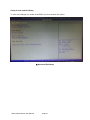
1
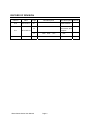
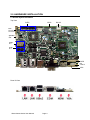
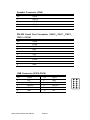
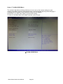
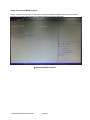
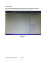
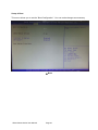
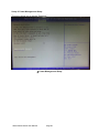
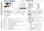
SB35-G2000 Series SBC industrial Motherboard User Manual 3.5” Industrial Single Board Computer With AMD Processor (2st Edition 2/20/2013) All information is subject to change without notice. Approved by SB35-G2000 Series User Manual Checked by Page 1 Prepared by RECORD OF REVISION Version Date V1.0 2013.Feb.1 Page Old Description all Initial Release Add Location of Connectors and Jumpers 11 V1.1 2013.Feb.20 17 SB35-G2000 Series User Manual New Description Remark CN5 Pin4: Page 2 +5V +12V Acknowledgments All other products’ name or trademarks are properties of their respective owners. AMI is a trademark of American Megatrends Inc. ITE is a trademark of Integrated Technology Express Inc. ® AMD is a trademark of AMD Corporation. ® Microsoft Windows is a registered trademark of Microsoft Corp. IBM, PC/AT, PS/2, and VGA are trademarks of International Business Machines Corporation. Sound Blaster is a trademark of Creative Labs ,Inc. Please be notified that all other products’ name or trademarks not be mentioned above are properties of their respective owners. SB35-G2000 Series User Manual Page 3 Packing List Before installation, please ensure the following items have been shipped: 1 x SB35-G200X 1 x VGA cable 1 x SATA Power cable 1 x SATA Signal cable 2 x RS232 cable 1 x USB cable(2 Connecter) 1 x DVD-ROM for manual (in PDF format) and drivers If any of these items should be missing or damaged, please contact your distributor or sales representative immediately. Ordering Information Model Number Description SB35-G2002-01 (Fanless Design) AMD T16R (615MHz) APU with GPU HD 6250, 3.5" SBC Board, Mini Card, 2GbE, 6COM, 8-bit GPIO, 6USB, VGA, HDMI, CFast, 12VDC SB35-G2003-01 (Fanless Design) AMD T40R (1 GHz) APU with GPU HD 6250, 3.5" SBC Board, Mini Card, 2GbE, 6COM, 8-bit GPIO, 6USB, VGA, HDMI, CFast, 12VDC SB35-G2004-01 AMD T40N (1 GHz) APU with GPU HD 6290, 3.5" SBC Board, Mini Card, 2GbE, 6COM, 8-bit GPIO, 6USB, VGA, HDMI, CFast, 12VDC SB35-G2006-01 AMD T56N (1.65GHz) APU with GPU HD 6320, 3.5" SBC Board, Mini Card, 2GbE, 6COM, 8-bit GPIO, 6USB, VGA, HDMI, CFast, 12VDC Optional Accessories 2.5” SATA Hard Disk Drive CFast Memory Card ADAPTER,12V,7.0A,84W. Heat Sink with Fan Audio Cable(Line in、Line out、MIC) SATA Power cable SATA Signal cable RS232 cable USB cable(2 Connecter) SB35-G2000 Series User Manual Page 4 Safety & Warranty 1. Read these safety instructions carefully. 2. Keep this user's manual for later reference. 3. For pluggable equipment, the power outlet must be installed near the equipment and must be easily accessible. 4. Keep this equipment away from humidity. 5. Put this equipment on a firm surface during installation. Dropping it or letting it fall could cause damage. 6. Make sure the voltage of the power source is correct before connecting the equipment to the power outlet. 7. Position the power cord so that people cannot step on it. Do not place anything over the power cord. 8. All cautions and warnings on the equipment should be noted. 9. If the equipment is not used for a long time, disconnect it from the power source to avoid damage by transient over-voltage. 10. Never pour any liquid into an opening. This could cause fire or electrical shock. 11. If any of the following situations arises, get the equipment checked by service personnel: a. The power cord or plug is damaged. b. Liquid has penetrated into the equipment. c. The equipment has been exposed to moisture. d. The equipment does not work well, or you cannot get it to work according to the user’s manual. e. The equipment has been dropped and damaged. f. The equipment has obvious signs of breakage. 12. DO NOT LEAVE THIS EQUIPMENT IN AN ENVIRONMENT WHERE THE STORAGE TEMPERATURE IS BELOW -20°C (-4°F) OR ABOVE 70°C (158°F). IT MAY DAMAGE THE EQUIPMENT. SB35-G2000 Series User Manual Page 5 CONTENTS RECORD OF REVISION ............................................................................................................... 2 1.0 INTRODUCTION ..................................................................................................................... 7 2.0 HARDWARE INSTALLATION ................................................................................................. 9 3.0 AMI BIOS SETUP ................................................................................................................. 21 4.0 DRIVER INSTALLATION ...................................................................................................... 28 SB35-G2000 Series User Manual Page 6 1.0 INTRODUCTION 1.1 About SB35-G2000 Single Board Computer With AMD Processor SB35-G2000 based on AMD Fusion technology delivers a complete, full-feature embedded platform and incorporate the new low-power, x86 CPU with a world-class DirectX 11-capable GPU on a single piece of silicon. It is the perfect solution for application that require low power and significant graphic performance in a small form factor. The SB35-G2000 integrate high performance solutions, support system memory DDR3 up to 4GB, three types of storage device are considered, SATA interface, mSATA and CFast. High speed internet connectivity, it offers two ports of Gigabit Ethernet. And rich IO interface, 6 COM ports, 6 USB and 8-bit digital IO. SB35-G2000 provide three types of display interface, VGA, HDMI and dual 24-bit LVDS, as well as it supports dual display feature through VGA+HDMI, VGA+LVDS or HDMI+LVDS.SB35-G2000 is a great choice for customers who used embedded board for high performance, multi-media and small form factor. It is ideal for applications such as industrial control,digital signage, transportation, POS, information Kiosk, medical, casino gaming and factory automation. 1.2 FEATURES Embedded AMD G-series Dual Core/Single CoreProcessor Low Power Consumption System Memory Support DDR3 up to 4GB. Multi Display Dual 24-bit LVDS, HDMI or VGA High Resolution Display HDMI up to 1920x1080, VGA1920x1200 (T56N up to 2560X1600) Support High Graphic Performance DirectX 11, 2D/3D Acceleration Support two GbE Rich I/O Interface 6 COM, 2 SATA, 6 USB, 8-bit GPIO Support 3 Types Storage Interface, SATA, mSATA, CFast Audio Interface Line-in, Line-out, MIC, Speaker Out Extended Interface Mini Card Socket 12V DC Input Wide Temperature Operation Dimension 146x101.6 mm (5.75” x 4”) SB35-G2000 Series User Manual Page 7 1.3 SPECIFICATIONS: System Processor Model Name SB35-G2006 SB35-G2004 SB35-G2003 SB35-G2002 APU T56N (1.65GHz) Dual Core T40N (1.0GHz) Dual Core T40R (1.0GHz) Single Core T16R (615MHz) Single Core GPU HD6320 HD6290 HD6250 HD6250 Chip Set AMD A55E System Memory 204-pin SODIMM x1, Max. 4GB DDR3-1333 (DDR3-1333 for T56N ) Ethernet Speed: 10/100/1000 Base-TX, Controller: x2 Intel® 82583V Connector: x2 RJ45 on rear IO side Storage SATA (3.0G/s) x2 ,CFast x1 mSATA optional (support either mSATA or full size mini card) x1 Audio Audio Chipset Realtek ALC269 Line-out, Line-in, MIC, Speaker out Display AMD G-series GPU Supports Hardware DirectX11 HDMI display resolution up to 1920x1080 VGA display resolution up to 1920X1200 (T56N up to 2560x1600) LVDS support dual channel 24-bit Expansion Full size mini card x1 IO Chipset Fintek F81866AD Rear IO Interface RJ45 GbE x2 ,USB 2.0 x2 ,COM (RS232/422/485) x1 ,HDMI x1 On Board IO Interface USB x4, COM (RS232) x5, VGA x1, LVDS Dual 24-bit x1 Audio Line-in, Line-out, MIC, 8-bit GPIO, Speaker out BIOS AMI Plug & Play BIOS Environment Operation Temperature 20°C ~ 60°C Storage Temperature 30°C ~ 80°C Operation Humidity 0~90% , non-condensing Power Input Single DC 12V Board Size 5.75" x 4" (146mm x 101.6mm) SB35-G2000 Series User Manual Page 8 2.0 HARDWARE INSTALLATION 2.1 General System Information Top View SATA GPIO DC12V MIC Line-in Line-out Speaker Out COM X5 USB X4 LVDS B/L control VGA Rear IO View SB35-G2000 Series User Manual Page 9 Bottom Side View SB35-G2000 Series User Manual Page 10 2.2 Location of Connectors and Jumpers Component Side Component Side Solder Side Solder Side SB35-G2000 Series User Manual Page 11 2.3 Mechanical Drawing Component Side Component Side SB35-G2000 Series User Manual Page 12 Solder Side Solder Side SB35-G2000 Series User Manual Page 13 2.4 List of Jumpers The board has a number of Jumpers that allow you to configure your system to suit your application. Label Function JP1 Power pin7 for SATA DOM JP2 Power pin7 for SATA DOM JP3 Clear CMOS JP4 AT/ATX Power mode JP5 LCD Backlight Voltage Selection JP6 LCD panel Voltage Selection JP7 COM2 Ring/+5V/+12V Selection 2.5 List of Connectors The board has a number of Jumpers that allow you to configure your system to suit your application. The table below shows the function of the board's connectors: Label Function CN1 Front Panel CN3 SATA connector CN4 SATA connector CN5 ATX 4Pin Power Connector CN6 SATA Power Connector CN7 Audio Connector CN9 Speaker Connector CN10 COM1 Connector CN11 COM5 Connector CN12 COM6 Connector CN13 COM3 Connector CN14 COM4 Connector CN15 USB Connector CN16 USB Connector CN17 PS2 KB/MS Connector CN18 LVDS Connector CN19 FAN Connector CN20 GIGA LAN CN21 GIGA LAN CN22 USB Dual Port Connector CN24 HDMI Connector CN25 Backlight Connector SB35-G2000 Series User Manual Page 14 CN26 VGA Connector CN27 Battery Connector CN28 COM2 Connector CN29 CFast Connector CN30 DDR3 Connector CN32 Mini Card CN33 SIM Card 2.6 Setting Jumpers You configure your card to match the needs of your application by setting jumpers. A jumper is the simplest kind of electric switch. It consists of two metal pins and a small metal clip (often protected by a plastic cover) that slides over the pins to connect them. To “close” a jumper you connect the pins with the clip. To “open” a jumper you remove the clip. Sometimes a jumper will have three pins, labeled 1, 2 and 3. In this case you would connect either pins 1 and 2 or 2 and 3. A pair of needle-nose pliers may be helpful when working with jumpers. If you have any doubts about the best hardware configuration for your application, contact your local distributor or sales representative before you make any change. Generally, you simply need a standard cable to make most connections. Pin7 Power Selection for SATA DOM JP1、JP2 Function 1-2 Closed Pin7 with power 1-2 Open Pin7 without power Clear CMOS Selection JP3 Function 1-2 Normal 2-3 Clear CMOS SB35-G2000 Series User Manual (Default) Page 15 (Default) AT/ATX Selection JP4 Function 1-2 Closed AT 1-2 Open ATX (Default) LCD Backlight Voltage Selection JP5 Function 1-2 +5V 2-3 +12V (Default) LCD Panel Voltage Selection JP6 Function 1-2 +5V 2-3 +3.3V (Default) COM2 Ring/+5V/+12V Selection JP7 Function 1-2 +12V 3-4 Ring 5-6 +5V (Default) 2.7 Connector Pin Assignment Front Panel Connector (CN1) Pin Signal 1 GND 2 PWR_BTN(-) 3 HDD_LED(-) 4 +3.3V 5 Buzzer 6 +5V 7 GND SB35-G2000 Series User Manual Page 16 8 PWR_LED(+) 9 GND 10 Reset(-) ATX 4Pin Power Connector (CN5) Pin Signal 1 NC 2 GND 3 GND 4 +12V SATA Power Connector (CN6) Pin Signal 1 +12V 2 GND 3 GNF 4 +5V Audio Connector (CN7) Pin Signal 1 MIC 2 MIC_VREF 3 GND 4 GND 5 LINEIN_L 6 NC 7 LINEIN_R 8 GND 9 GND 10 NC 11 LINEOUT_L 12 LINEOUT_R 13 GND 14 GND SB35-G2000 Series User Manual Page 17 Speaker Connector (CN9) Pin Signal 1 SPK_R- 2 SPK_R+ 3 SPK_L+ 4 SPK_L- RS-232 Serial Port Connector (CN10、CN11、CN12、 CN13、CN14) Pin Signal 1 DCD# 2 DSR# 3 RXD 4 RTS 5 TXD 6 CTS# 7 DTR# 8 RI# 9 GND USB Connector (CN15,CN16) Pin Signal Pin Signal 1 +5V 2 GND 3 DATA0- 4 GND 5 DATA0+ 6 DATA1+ 7 GND 8 DATA1- 9 GND 10 +5V SB35-G2000 Series User Manual Page 18 1 2 3 5 4 7 9 8 6 10 PS2 Keyboard and Mouse Connector (CN17) Pin Signal 1 KBDATA 2 KBCLK 3 GND 4 +5V 5 MSDATA 6 MSCLK LVDS Connector (CN18) Pin Signal Pin Signal 1 LVDS_BKLEN 2 LVDS_BKLCTL 3 PPVCC 4 GND 5 LVDS_TXLCLK# 6 LVDS_TXLCLK 7 PPVCC 8 GND 9 LVDS_TXL0# 10 LVDS_TXL0 11 LVDS_TXL1# 12 LVDS_TXL1 13 LVDS_TXL2# 14 LVDS_TXL2 15 LVDS_TXL3# 16 LVDS_TXL3 17 LVDS_DDCPDATA 18 LVDS_DDCPCLK 19 LVDS_TXU0# 20 LVDS_TXU0 21 LVDS_TXU1# 22 LVDS_TXU1 23 LVDS_TXU2# 24 LVDS_TXU2 25 LVDS_TXU3# 26 LVDS_TXU3 27 PPVCC 28 GND 29 LVDS_TXUCLK# 30 LVDS_TXLCLK Fan Connector (CN19) Pin Signal 1 GND 2 Fan control 3 Fan-IN SB35-G2000 Series User Manual Page 19 Backlight Connector (CN25) Pin Signal 1 Backlight Voltage Input 2 Backlight control 3 GND 4 GND 5 Backlight Enable VGA Connector (CN26) Pin Signal 1 VSYNC 2 HSYNC 3 GND 4 DDC_SCL 5 DDC_SDA 6 CRT_PLUG 7 BLUE 8 GND 9 GREEN 10 GND 11 RED 12 GND 13 +5V Battery Connector (CN27) Pin Signal 1 RTCBAT 2 GND SB35-G2000 Series User Manual Page 20 3.0 AMI BIOS SETUP SB35-G2000 Series User Manual Page 21 Setup 1: The Main BIOS Menu. The sections that follow provide guidelines on how to set up the various settings in each section of the BIOS. We have concentrated only on those settings that may need changing, if a setting does not appear in this document, leave it as you found it. Press Enter on a main menu option to go into that section. To return to the Main Menu from within a section, press Escape. The Main BIOS Menu SB35-G2000 Series User Manual Page 22 Setup 2: Advanced BIOS Features As you can see from screen 2, there are numerous advance settings which you can select if required. For most cases leaving the default setting should be adequate. Advanced BIOS Features SB35-G2000 Series User Manual Page 23 Setup 3: Chipset Here you can setup the contents of the chipset buffers. It is closely related to the hardware and is therefore recommended that you leave the default setting unless you know what you are doing. Having an incorrect setting can make your system unstable. Chipset SB35-G2000 Series User Manual Page 24 Setup 4: Boot This menu allows you to set the “Boot Configuration”. You can make changes as necessary. Boot SB35-G2000 Series User Manual Page 25 Setup 5: Power Management Setup This menu allows you to set the “Password”. Power Management Setup SB35-G2000 Series User Manual Page 26 Setup 6: Save and Exit Setup To save any changes you made to the BIOS you must choose this option. Save and Exit Setup SB35-G2000 Series User Manual Page 27 4.0 DRIVER INSTALLATION The SB35-G2000 comes with a DVD-ROM that contains all drivers and utilities that meet your needs. Follow the sequence below to install the drivers: Step 1 – Install APU Driver Step 2 – Install LAN Driver Step 3 – Install Audio Driver USB 2.0 Drivers are available for download using Windows Update for both Windows XP and Windows 2000. For additional information regarding USB 2.0 support in Windows XP and Windows 2000, please visit www.microsoft.com/hwdev/usb/. Please read instructions below for further detailed installations. 4.1 Installation: Insert the SB35-G2000 DVD-ROM into the DVD-ROM Drive. And install the drivers from Step 1 to Step 3 in order. Step 1 – Install Intel APU Driver 1. Click on the APU Driver folder and select the OS folder your system is 2. Double click on the setup.exe file located in each OS folder 3. Follow the instructions that the window shows 4. The system will help you install the driver automatically Step 2 – Install Intel LAN Driver 1. Click on the Ethernet Driver folder and select the OS folder your system is 2. Double click on the setup.exe file located in each OS folder 3. Follow the instructions that the window shows 4. The system will help you install the driver automatically Step 3 – Install Audio Driver 1. Click on the Audio Driver folder and select the OS folder your system is 2. Double click on the setup.exe located in each OS folder 3. Follow the instructions that the window shows 4. The system will help you install the driver automatically SB35-G2000 Series User Manual Page 28