1
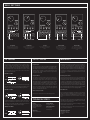
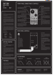
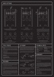
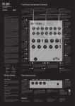
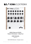
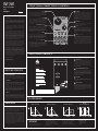
SVF 201
ANALOG STATE VARIABLE
FILTER
_
USER MANUAL
FRONT PANEL CONNECTIONS & CONTROLS
Cutoff
(CV Input) Cutoff
We are KOMA Elektronik, we come from Berlin, a town
filled with musicians, producers, artists and remixers.
Music is everywhere. We make music ourselves as well,
sometimes successful, sometimes less successful,
but we have a good time doing so. And that for us is
what it’s all about: the mere fun of creating sounds
nobody else made before; the fun of crossing all borders and let your imagination go, the fun of exploring
musical boundaries and not looking back!
Our filter resembles that vision: compact, yet powerful,
the SVF-201 is a state variable filter for the Eurorack
modular synthesizer system. Its circuit is built up with
optical parts (vactrols) delivering excellent studio audio quality and an unique warm analogue sound.
The module uses parallel mounted PCBs so it can be
used in skiffs as well as in big cases, the total depth
is less than 4 cm. The SVF-201 comprises 4 audio outputs that can be used independent of each other at
the same time, a High Pass, Band Pass, Low Pass and
the unique first ever CV’able Mix Out, which allows you
to sweep continuously through the other three outputs by means of a knob and control voltage. Now wire
up that filter and get funky!
2
7
Resonance (CV Input)
CV input for resonance (Q) modulation. It has the same
specifications as the Cutoff CV input.
3
vieleicht
8
Defines the amplitude of the signal that will travel into
the filter. At the counter-clockwise (CCW) position
there will be no signal going into the module at all, at
around 9 o’ clock the signal will be at unity gain and at
full clockwise (CW) position the signal will be boosted
by about +6dB
(Audio Input) AUDIO IN 4
Select (CV Input)
CV input to select which output will be present on the
Mix Out audio output. This CV input accepts 0 – 5V
(unipolar). If there is no CV signal sent into the input
in the Select jack, the attenuator acts as a normalled
CV source from 0 – 5V for manual sweeps through the
filter types.
9
Audio input to the filter. There’s plenty of gain here,
so take care when setting the input level if you do
not want to distort your signal. Overdriving the input
can get you amazingly rich and experimental sounds
though, so try it out once and see if you like it!
(Audio Outputs) AUDIO Out
RESONANCE
Sets the Q of the filter, better known as resonance. The
resonance of a filter determines the gain increase of
the signal at the cutoff frequency. Set it low (CCW) to
leave the signal gain at cutoff frequency at zero and
turn it CW to hear plenty of resonance at the given cutoff frequency.
Be aware of the fact that the filter will start self-oscillating when you are at or near maximum resonance!
CV input for cutoff modulation. This input reacts to bipolar CVs, internally only a 5V peak-to-peak signal is
processed, so every CV signal exceeding a voltage of
5Vpp will have to be attenuated to use the full range
of the CV input.
Input Attenuator / Gain
We tried to make this module just as versatile as our
other products and are confident we succeeded in
that! Before you get started, please let us introduce
ourselves to you…
6
Sets the cutoff frequency for the filter, simultaneously
for all three filter characteristics. The full CCW position
sets the cutoff frequency to the lowest and the full
CW position to the highest frequency.
Dear KOMA user,
Thanks for purchasing one of our Eurorack modules:
the SVF-201 Analogue Vactrol State Variable Filter!
We are very happy you decided to add a nice shade
of white (with a backlit knob) to your Eurorack Modular
system!
1
Mix Out (Audio Output)
The Mix Out is a special output of the SVF-201 which
contains all three of the above outputs (LP, BP and
HP). You can sweep continuously through these three
outputs with a control voltage signal from 0 – 5V. This
output has more internal gain than the three different
single outputs, so signals taken from this output will
have more overdrive / distortion than their respective
partners. The signal levels themselves are identical
though.
5
These are the three outputs for the corresponding
filter characteristics. All three outputs are available
at the same time without the need to switch anything
around. When changing the cutoff frequency or the
resonance of the filter you change these features for
all of the outputs simultaneously.
REAR PANEL CONTROLS
All the best from Berlin,
1
The KOMA Elektronik Team
+5V rail choice
If you have a +5V power supply on your bus board rails
and you want to use it with the KOMA Elektronik SVF201 then you can change the second jumper setting
from ‘Onboard’ to ‘Bus’. Don’t worry, the two +5V rails
can never be connected together, regardless of how
you place the jumper.
Warning!
Please do
GETTING STARTED
2
not touch or change
the four trimmers on the
If you have access to an ISP programmer and you
are familiar with programming micro controllers you
can use the 6-pin ISP header for connecting your
programmer to the module. You will find the pre-loaded
code as well as some alternatives on our homepage at
www.koma-elektronik.com
top as they are already
set to best filter behaviour
1. Unpack your new gadget
and it is complicated
The package comes with the SVF-201 filter module, a 16-pole
ribbon cable with connectors, a small bag with four screws
and washers for front panel mounting and this manual.
to reset them after you
First off; be sure that the bus board of your system is unpowered. Take the connector cable and insert it into the bus
board of your modular system. Be very careful when doing
so because it is easy to shift the connector and place it incorrectly.
The red marked side needs to be connected on the lower
side of a Doepfer bus board and on the marked side of the
module (-12V rail). If attached correctly the keyed header
will have the right orientation for keyed power systems (e.g.
uZeus). See the rear panel picture for more clarity.
3. Power up
Power up your system and check if all supply rails are up and
running (+/-12V and possibly +5V), often there are indication
LEDs on the bus board showing if the rails are working properly. When the power is connected properly, a white light – a
nice nimbus - underneath the big Cutoff knob should light
up.
FEATURES
3
turned them (also just a
safe yourself the hassle
4
and stay away from these
trimmers!
LED Corona
If you don’t like the white light around the Cutoff knob
simply take out the jumper above ‘LED Corona’ (and try
not to lose it!).
little bit), so please just
2. Connections
ISP programming header for Mix Out
Red
stripe
here!
POWER CONNECTION
Always make sure you align the red stripe on the power
connector to the red stripe marker on the module. To
be extra safe, make sure that the cable you are using
is correctly wired, which means that one connector
faces up and the other down when you hold the cable
in front of you with the flat side up.
-12V
Gate
CV
+5V
+12V
GND
GND
GND
-12V
FILTER MODES
LOWPASS (LP OUT)
BANDPASS (BP OUT)
Amplitude
The use of the FT201 is pretty straight forward. There is the
CUTOFF knob with which you set the cutoff frequency for the
filter, simultaneously for all three filter characteristics. Fully
counter-clockwise sets the cutoff frequency to the lowest
and fully clockwise to the highest frequency.
HIGH PASS (HP OUT)
MIX OUT
(LP/BP/HP MIXED OUT)
The RESONANCE knob sets the Q of the filter, better known
as resonance. The resonance of a filter determines the gain
increase of the signal at the cutoff frequency. Set it to low
(CCW) to leave the signal gain at cutoff frequency at zero
and high (CW) to hear plenty of resonance at the given cutoff frequency. Be aware of the fact that the filter might start
self-oscillating when you are at or near maximum resonance.
The MIX OUT is a unique output that combines all filter types.
You can sweep through from lo pass to band pass to hi pass
with the SELECT potentiometer. The SELECT potentiometer is
also able to be controlled via CV.
IMPRINT
KOMA Elektronik GmbH is a subsidiary
company of KOMA Elektronik B.V.
Vertretungsberechtigte
Geschäftsführer / Managing Director:
Christian Zollner & Wouter Jaspers
Sitz der Gesellschaft / Registered Office:
Berlin, Germany
Registergericht / Court of Registration:
Amtgericht Berlin-Charlottenburg
Registernummer : HRB 145453
Umsatzsteuer ID / VAT ID: DE285522050
KOMA Elektronik GmbH
Mahlower Strasse 24
12049 Berlin-Neukölln
Germany
BASIC SETTINGS
AUDIO IN
AUDIO out
LFO IN
AUDIO IN
3 OUT to channel mixer
AUDIO out
AUDIO IN
AUDIO out
AUDIO IN
AUDIO out
DISTORTED LOWS
3 CHANNEL MIXER
OSCILLATOR
SUB BASS RESONANCE
FILTER TYPE SWEEP
When the input gain is all the way up,
the signal is distorted along with high
resonance, creating a gritty sound.
Take each output channel into its own
channel on a mixer to blend between
each filter type manually.
Patch the HI PASS Audio Output back
into the AUDIO Input to create an
oscillator.
When using the HI PASS output at a
very low cutoff and high resonance,
sub bass frequencies are added
around the Q frequency.
Patch an LFO into the SELECT CV
input to sweep through the different
filter types creating completely new
sounds!
CV THEORY
TIPS & TRICKS
WARRANTY
The concept of control voltage (CV) is not hard to understand: instead of turning a knob on your pedal, you simply
connect a voltage – the control voltage – to the corresponding CV input that does the job for you. All of the CV inputs
theoretically accept control voltages from -100V to +100V
though a range from -5V/-12V/-15V to +5V/+12V/+15V is
more common and usable.
Using the Input
The Input Attenuator / Gain control defines the amplitude of
the signal that will travel into the filter. At a counter-clockwise (CCW) position there will be no signal going into the
module at all, at around 9 o’ clock the signal will be at unity
gain and at full clockwise (CW) position the signal will be
boosted by about +6dB.
KOMA Elektronik warrants its products to be free of defects
in materials / workmanship and conforming to specifications at the time of shipment for a period of two years from
the date of purchase. During the warranty period, any defective products will be repaired or replaced at KOMA Elektronik’s option, on a return-to-factory basis. This warranty only
covers defects that KOMA Elektronik determines are no fault
of the user.
Using the Mix Out
Returning Your Product?
The Mix Out is a special output of the SVF-201 which contains all three of the outputs (LP, BP and HP). You can sweep
continuously through these three outputs with a control
voltage signal from 0 – 5V. The diagram on the front side of
this manual (under FILTER MODES, far right) shows the corresponding loudness curves of the filter characteristics in
correlation with the CV input. Low pass appears at 0.25V to
2.25V, pure bandpass between 2.25V and 2.75V and from
2.75V to 4.75 you’ll get high pass as an output signal. All
outputs crossfade into each other.
You must obtain prior approval in the form of an RMA (Return
Material Authorization) number from KOMA Elektronik before
returning any product. Email [email protected]
to request the RMA number. All products must be packed
carefully and shipped with all the originally sent content.
Sorry, the warranty will not be honored if the product is not
properly packed. Once you have received the RMA number
and carefully packed your product, ship the product to KOMA
Elektronik and include your return shipping address.
BIPOLAR CV SIGNALS
The incoming bipolar CV signal is shifted around the voltage
that you select with the corresponding knob. Example: if you
insert a -5V to a +5V sine wave while adjusting the bias:
BIPOLAR CV SIGNALS
What will we do?
How to clean your SVF 201
Clean the front panel with a cloth and rubbing alcohol.
TECHNICAL SPECS
A similar thing happens to unipolar CV signals: their point of
origin (0V) is shifted by the amount set with the corresponding knob. In other words: you add the voltage of your knob to
the voltage of your incoming unipolar CV signal.
UNIPOLAR CV SIGNALS
Casing
2mm Aluminum front
panel, powder coated
white with silkscreen
printing.
Dimensions
12 HP / 40mm depth.
Shipping Weight
250 gram / 0.55 lbs.
Power requirements
80 mA @ +12V.
11 mA @ -12V.
Once received, we will examine the product for any obvious
signs of user abuse or damage as a result of transport. If the
product has been abused, damaged in transit or is out of
warranty, we will contact you with an estimate of the repair
cost.
Warranty work will be performed and KOMA Elektronik will
ship and insure your product to your address free of charge.
How to initiate a warranty return
Please initiate your warranty online by sending an email to
[email protected].
If you do not have web access, fill out your personal information on a letter and mail to:
KOMA Elektronik GmbH
Mahlower Straße 24,
12049 Berlin-Neukölln
Germany