1
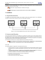
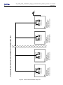
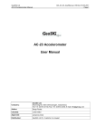
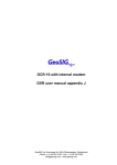
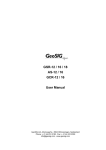
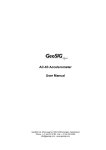
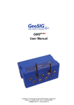
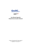
GSR-12 / 16 / 18 / 24
AS-12 / 16
GCR-12 / 16
User Manual Appendix K
Indoor Interconnected Recording Networks
GeoSIG Ltd, Ahornweg 5A, 5504 Othmarsingen, Switzerland
Phone: + 41 44 810 2150, Fax: + 41 44 810 2350
[email protected], www.geosig.com
ii
GS_GSR_GCR_UserManual_App_K_Interconnection_ILFDC_V02.doc / 20.10.2010
Appendix K
Document Revision
Author
Checked
Approved
Mischa Sabathy
Alexandre Beaud
Talhan Biro
Version
01.10.2009
20.10.2010
Action
First issue: Merged information’s from STC into one appendix
Update chapter 1 - MAE
Disclaimer
GeoSIG Ltd reserves the right to change the information contained in this document without notice. While the information contained
herein is assumed to be accurate, GeoSIG Ltd assumes no responsibility for any errors or omissions.
Copyright Notice
No part of this document may be reproduced without the prior written consent of GeoSIG Ltd. The software described in this document
is furnished under a license and may only be used or copied in accordance with the terms of such a license.
Trademark
All brand and product names mentioned are trademarks or registered trademarks of their respective holders.
All rights reserved.
GeoSIG Ltd
Switzerland
GS_GSR_GCR_UserManual_App_K_Interconnection_ILFDC_V02.doc / 20.10.2010
Appendix K
3
Table of Contents
1. Introduction...................................................................................................................... 4
2. Description and Functionality........................................................................................... 4
2.1. Common Functionality ............................................................................................................................4
2.1.1. Type CCL:
(Common Time, Common Trigger, Local Communication) .......................................4
3. Installation ....................................................................................................................... 5
3.1. Physical Interconnection .........................................................................................................................5
3.2. Interconnected Recorders.......................................................................................................................5
3.2.1. CCL..................................................................................................................................................5
3.2.2. Software Configuration ....................................................................................................................7
3.3. Verification of the Installation ..................................................................................................................8
GS_GSR_GCR_UserManual_App_K_Interconnection_ILFDC_V02.doc / 20.10.2010
Appendix K
4
1. Introduction
When interconnection is involved, more options are available in terms of connections, data flow,
accessibility, and cost. This manual shows a drawing for an indoor interconnected recording network. This
interconnection is for indoor installations only, where the danger of lightning is minimal.
a
Use this interconnection for indoor applications only
a
The interconnection network is limited to a cable length of 1000 m and a maximum
station number (Master and Slaves) of 10 instruments.
2. Description and Functionality
2.1. Common Functionality
Connections: Several recorders with internal or external sensors are placed on site and are interconnected
with one cable while galvanically isolated from each other.
Common Timing: One of the interconnected recorders (commonly referred to as the Software Master) is
enabled to synchronise and update the internal clock of each of the other recorders (commonly referred to as
Software Slaves) via the network to achieve Common Timing. All stations within the network use this
common time information to synchronise their internal time. The time synchronisation is a permanent task for
the Software Master. The stations within the network permanently check their synchronisation status. In case
of not having the network time information available, the Slave stations base on their internal real time clock.
The time of the last successful synchronisation is available in the status information of a Slave station and is
written into every event header. A GPS time source can be connected to the Software Master to achieve the
time synchronisation of the whole array to the absolute time, which allows easier correlation with recordings
made by other arrays or recorders.
Common Trigger: Triggering functionality of each recorder can be controlled using three flags: 'Internal
Trigger', 'Network Trigger Output' and 'Network Trigger Input'. By enabling or disabling these flags the
behaviour of each station can be defined precisely as needed in the particular application. This functionality
can be summarised as follows:
• Enable / disable self trigger:
The station triggers if an internal trigger condition is fulfilled and the 'Internal Trigger' flag is
enabled.
• Enable / disable sending trigger to network:
The station transmits an active trigger message to the network if an internal trigger condition is
fulfilled and the 'Network Trigger Output' flag is enabled.
• Enable / disable accepting trigger from network:
The station triggers if an active trigger message arrives from the network and the 'Network Trigger
Input’ flag is enabled.
If a station is not synchronised to the network it records based on the specified internal trigger condition. An
output for Local Communication is available at each recorder for local data retrieval and setting of
parameters. The reliability of the monitoring network is high, because a malfunction of a recorder would
affect only the location of malfunction in the array. If the network is interrupted, each of the recorders will
perform as a stand-alone recorder by recording whenever the instrument’s event-recording trigger level is
reached.
2.1.1. Type CCL:
(Common Time, Common Trigger, Local Communication)
This type of array enables common triggering and common time in the simplest form. The data are stored
locally in every recorder and have to be retrieved locally from each recorder separately, due to the
GS_GSR_GCR_UserManual_App_K_Interconnection_ILFDC_V02.doc / 20.10.2010
Appendix K
5
availability of Local Communication only. Similarly, the setting of parameters of each recorder has to be
performed on the site of each recorder.
a
A Cable with a single twisted pair is sufficient for this type.
This indoor type is only for the CCL! Do not use for CCC and CCM type!
3. Installation
3.1. Physical Interconnection
To establish the interconnection between the recorders, connect the supplied cable to the “INTERCON”
connector on the front of the recorder. The pin out of the cable is as follow.
“INTERCON“
Connector
(cable side)
Pin 6
Pin 7
“INTERCON“
Connector
(cable side)
Pin 6
Pin 7
“INTERCON“
Connector
(cable side)
Pin 6
Pin 7
Figure 1. Pin out of the supplied interconnection cable for three recorders
3.2. Interconnected Recorders
In an Interconnection Network not all recorders are configured in the same way from the hardware and from
the software point of view. The text in the Figures below each recorder describes its configuration and role in
the network. The recorders themselves are identified with labels containing the same text. The following
Chapters describe this issue for the different types of networks.
The individual recorders are pre-configured (hardware and software) in the factory.
a
Do not change the interconnection network specific configuration as described below
unless there is a strong reason to do so (check with GeoSIG Ltd.)!
3.2.1. CCL
The following different configurations are possible (see Figure 2):
• The first recorder in the bus is configured as Network Driver and has therefore jumpers J91 and
J92 inserted on the internal interconnection card GS_ICC_V05. There can only be one Network
Driver!
• The first recorder in the bus is configured as Software Master, whereas all the other recorders are
configured as Software Slaves. Refer to Chapter “Software Configuration” below
• If a GPS is available it is connected to the Software Master (first instrument)
To summarise, there are two types of instrument configurations:
• GXR Interconnection Master (first)
• GXR Interconnection Slave (all, except first)
Figure 2. Interconnection Network setup CCL
Interconnection CCL
GXR Interconnection Slave
- No network driver
(J91 and J92 not inserted)
- Software slave configuration
GXR n
GS_ICC.V05.A1
Interconnection CCL
GXR Interconnection Slave
- No network driver
(J91 and J92 not inserted)
- Software slave configuration
GXR n - 1
GS_ICC.V05.A1
Interconnection CCL
GXR Interconnection Slave
- No network driver
(J91 and J92 not inserted)
- Software slave configuration
GXR 2
GS_ICC.V05.A1
Interconnection: Common Time, Common Trigger, Local Communication (CCL)
Interconnection CCL
GXR Interconnection Master
- Network driver
(J91 and J92 inserted)
- Software master configuration
GXR 1
GS_ICC.V05.A1
GPS
(optional)
6
GS_GSR_GCR_UserManual_App_K_Interconnection_ILFDC_V02.doc / 20.10.2010
Appendix K
GS_GSR_GCR_UserManual_App_K_Interconnection_ILFDC_V02.doc / 20.10.2010
Appendix K
7
3.2.2. Software Configuration
In order to allow Common Time and Common Trigger in the network the recorders need to be configured to
this respect.
Figure 3 shows the configuration of the Software Master. The following ticks are fixed and cannot be
changed.
Software Master:
• Enable Network Synchronisation
• Network Master Mode
Figure 4 shows the configuration of the Software Slave. The following ticks are fixed and cannot be changed.
Software Slave:
• Enable Network Synchronisation
• Network Master Mode IS NOT TICKED
Optional:
• Input Network Trigger
• Output Network Trigger
• Synchronise Slave Clock to Network Clock
For a description of the Synchronisation options please refer to Chapter 1. For more details on the use of
GeoDAS please refer to the GeoDAS Software Manual.
Figure 3. Software Master configuration in GeoDAS
GS_GSR_GCR_UserManual_App_K_Interconnection_ILFDC_V02.doc / 20.10.2010
Appendix K
8
Figure 4. Software Slave configuration in GeoDAS
3.3. Verification of the Installation
If the network is synchronised (Common Time and Common Trigger are working) the network status of every
recorder in the network, shows the word Synchronised (see above Figures 3 and 4 where the opposite is
indicated) in GeoDAS. The synchronisation of the date and time of all Software Slaves to the Software
Master should be verified and also the network triggering options. The update of the date and time of the
slave stations can take several minutes.
A simple way to check the wiring during the installation is to verify the arrival of the network signals to an
instrument. For this test the recorders need to be configured correctly. The following LED’s can be found on
the interconnection cards (GS_ICC_V5) inside the recorder (by removing the black plastic cover):
a
Caution: High Voltage!
If you remove the black plastic covering the base part of the recorder housing do not
touch any electronics inside.
• LED90, yellow:
• LED91, red:
• LED92, green:
Blinks in all recorders
Blinks in the recorders configured as Network
Blinks in the recorder configured as Software Master and during a trigger
also in the corresponding Software Slave.
The communication option can be tested by simply trying to establish a connection to the instruments
from a Computer running GeoDAS. The standard communication speed for Interconnection Networks
is 38’400 Baud.