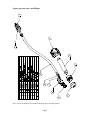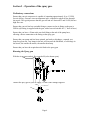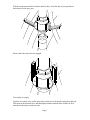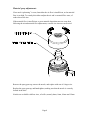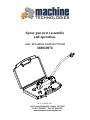
1
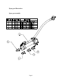
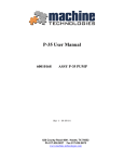
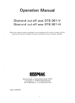
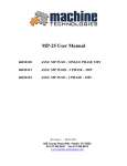
Spray gun (wet) assembly
and operation.
ASSY, KIT SPRAY NOZZLE-8"WAND
#60010076
REV- 4 APRIL 2015
620 County Road 4841. Haslet, TX 76052
Ph 817.636.5637 Fax 817.636.5675
www.machine-technologies.com
Contents
Page
Section 1 - General Safety information.........................................................................2
Danger ........................................................................................................................2
Section 2 – Spray gun description / Views....................................................................3
Spray gun function.....................................................................................................3
Spray gun illustrations...............................................................................................4
Spray gun assembly. ...............................................................................................4
Spray gun cap, base, and fittings............................................................................5
Section 3 – Operation of the spray gun.........................................................................6
Preliminary connections ............................................................................................6
Running the Spray gun ..............................................................................................6
Material spray adjustments .......................................................................................8
Section 4 - Spray Gun clean up, gun care, and simple trouble shooting .....................9
Cleaning......................................................................................................................9
Gun care .....................................................................................................................9
Trouble shooting ......................................................................................................10
Blockage removal ..................................................................................................11
LIMITED WARRANTY POLICY............................................................................12
Page 1
Section 1 - General Safety information
Danger
Follow these instructions very carefully, in order to avoid injury to yourself or others.
NEVER look directly into the nozzle.
Always keep the nozzle pointed away from people and animals.
Never disassemble the spray gun while material is flowing, or when air is flowing.
Never use sharp objects to clean the spray gun.
Page 2
Section 2 – Spray gun description / Views
Spray gun function
The spray gun is pneumatically and hydraulically powered.
Pneumatically by the air pressure used to help “atomize” the material, and hydraulically
by the material pushed from the pump unit through the chosen nozzle.
The spray gun is coupled to the material supply via the cam-lock fitting.
Material is pumped from the pump unit through a hose into the spray gun.
As the material passes through the interchangeable nozzle, inside the spray gun, air is
forced into the stream of material, causing the material to “atomize” or breakup into a
“spray”. The spray is directed towards the wall or structure to be coated, and moved
around to evenly coat the area.
Do not apply too much material to one spot at anyone time, as the material will tend to
“run” or “slump” and may fall from the area being coated.
Page 3
Spray gun illustrations
Spray gun assembly.
Page 4
Spray gun cap, base, and fittings
Note. Some items might not be available individually due to assembly practices
Page 5
Section 3 – Operation of the spray gun.
Preliminary connections
Ensure that your air compressor is capable of outputting approximately 10 to 13 CFM,
free air delivery. Pressure is not an important issue, compared to physical flow through
the nozzle. The typical pressure that the gun will run at is between 25 and 50 PSI, but at a
high flow rate.
Ensure that your air line has a suitable fitting to connect to the air fitting on the gun (a
GEKA style fitting is supplied with the gun, with a hose tail suitable for ½” bore air hose)
Ensure that you have a 25mm male cam-lock fitting at the end of the pump hose,
allowing a direct connection to the fitting on the spray gun.
Ensure that your pump unit has hoses primed, and ready to discharge, a smooth, wet,
lump free grout mix. Any lumps in the mix will increase the likelihood, of a blockage in
the nozzle, the smaller the nozzle, the smaller then lump.
Ensure that you have the required nozzle fitted to the spray gun.
Running the Spray gun
With the air pressure and air flow turned off (valve shown open),
connect the spray gun to your air supply, via the GEKA fittings supplied.
Page 6
With the pump unit turned off, and no material flow, clean the end of your grout hose,
and connect to the spray gun.
Ensure that both cam-locks are engaged.
Turn on the air supply.
Open the air control valve on the spray gun, so that air can be heard coming from the gun.
Then turn on the material flow, and then adjust both the material flow and the air flow
until the desired spray results are seen.
Page 7
Material spray adjustments
If too much “splattering” is seen, then either the air flow is insufficient, or the material
flow is too high. To remedy this either readjust the air and /or material flow rates, of
reduce the nozzle size.
If the material flow is insufficient, or poor material deposition rates are seen, then
following the air and material flow adjustments, a nozzle size increase can be tried.
Remove the spray gun cap, remove the nozzle, and replace with one of a larger size.
Replace the spray gun cap, and hand tighten, making sure that the nozzle is correctly
located in the base.
Nozzles are available with four sizes, of orifice, namely 6mm, 8mm, 10mm and 12mm.
Page 8
Section 4 - Spray Gun clean up, gun care, and simple trouble
shooting
Cleaning
After use, or sometimes during use, the gun will start to suffer from material build up,
either through being handled by dirty hands, being placed in or on fresh material, or from
back spray.
Any material must be removed before it hardens, using a warm water and soap solution.
Ensure that the material pump is turned off, and the air pump be turned off and
discharged before any disassembly is carried out.
Avoid the use of sharp objects to remove any hardened material, or damage could result
to the alloy gun body, the polymer end cap or the nozzle.
Avoid the use of caustic cleaning solutions, or damage to the alloy gun base will result.
Gun care
It is suggested that a de-moisturizing agent such as WD-40® be applied to the cleaned
nozzles and base before packing, to help keep the parts from corroding and rusting.
Individually wrap each nozzle, in a wipe cloth dampened with WD-40® to prevent rusting
and damage.
Once cleaned, replace the spray cap onto the spray gun base to prevent loss.
Ensure that the rubber seal fitted to each of the air connections is in good condition, and
NOT oiled.
Ensure that the sealing washer fitted inside the cam-lock fitting is in good condition and
NOT oiled, or contaminated with hardened material.
Page 9
Trouble shooting
The spray gun, is a simple, mechanically operated component, comprising of few parts.
In the event of a malfunction of the spray gun, it should be obvious as to the reason for
malfunction, and to the solution, however the following can occur.
If the material being supplied to the spray gun has not been mixed well, or poor quality
materials have been added to the mix, such as larger particles of stone, rock or similar,
then the spray gun will “block”, allowing only air to spray out.
A blockage can manifest itself in a couple of ways, such as a reduction in the material
flow rate, being a partial blockage, causing a poor spray coverage, or the material flow
suddenly stopping, being a full blockage, causing not coverage.
A partial blockage will likely keep reoccurring reflecting the poor quality of the mix, but
will most likely not stop the job, except for a possible poor finish to the coated surface,
the effects of which could be reduced by setting up the gun to use a larger nozzle, if
possible.
A full blockage will cause the material feed pipe to suddenly swell in diameter, and for it
to straighten out as the internal pressure builds. In the event of a blockage, STOP the
pump immediately, shut off the air at the air valve on the gun, and perform the following
as soon as possible.
Page 10
Blockage removal
To remove the blockage, all pressure inside the material hose must be relieved, this can
be done by leaving for a short period of time until the pressure naturally dissipates, or by
turning the pump to “reverse” for a couple of seconds.
NOTE. Do not run the pump in reverse for more than a second or two or the “blockage”
may get sucked back into the material hose, requiring further removal, and/or the pump
may become damaged.
•
Once the pressure in the material hose is removed, unclip the cam-locks on the
material hose connection, and remove the hose from the back of the gun.
•
Apply a water hose the front of the spray gun through the nozzle to “flush out the
blockage. Doing this over a clean hard standing will allow the easier detection of
the blockage, allowing the reason for blockage to be determined easier.
•
Keep flushing the spray gun until a clear sight path can be established through the
gun. Pay particular attention to the material fitting when flushing.
•
Turn the pump ON, for approx 10 seconds, with the material hose placed in a
waste collection vessel, allowing the contaminated material to purge from the
pipe.
•
Turn OFF the pump, clean the hose end, and reassemble the gun to the material
hose, making sure the cam-locks are secure.
•
Open the air valve, and re-start the pump, to continue spraying.
It is not recommended that the compressed air in the pipe be used to “reverse” purge the
material from a disconnected cam-lock fitting.
Page 11
LIMITED WARRANTY POLICY
Machine Technologies warrants each of its new machines to be free of
defects in material and workmanship under normal use and services for a
period of one (1) year from the date of delivery.
The warranty is issued ONLY to the INITIAL USER. The warranty period
begins when the product is delivered to the initial user or when first put into
service, whichever occurs first. Said warranty is void if the machine is
subject to misuse, neglect, accident or abuse.
Machine Technologies’ obligation under this warranty is limited to
correcting without charge, at its warehouse, any parts or parts thereof which
shall be returned to its warehouse, transportation/shipping prepaid and upon
Machine Technologies’ examination proves to have been originally
defective. Correction of such defects by repair or replacement shall
constitute fulfillment of all obligations to the initial user. This warranty does
not include labor or transportation charges unless specifically identified and
authorized in writing by Machine Technologies. Nor does the warranty
apply to any unit upon which repairs or unauthorized alterations have been
made.
The warranty does not apply to normal maintenance service or to normal
replacement of certain machine parts which are subject to normal wear
(including but not limited to pins, bushings, rotors, stators, hoses, spray
caps, spray nozzles, mixing shafts, shaft couplings and connectors, dosing
shafts, pump shafts, filter elements and tires).
THIS IS A LIMITED WARRANTY AND IS IN LIEU OF ANY OTHER
WARRANTIES, EXPRESSED OR IMPLIED, INCLUDING ANY
WARRANTY OF MERCHANTABILITY OF FITNESS FOR A
PARTICULAR PURPOSE. In no event shall Machine Technologies be
made liable for incidental, general or consequential damage, loss or any
expense directly or indirectly related and resulting from use or lack of use
caused by delay in delivery, parts failure, or any other causes associated with
the product use. No person, firm or corporation is authorized to assume for
Machine Technologies any other liability in connection with the sale of
Machine Technologies products.
Page 12