1
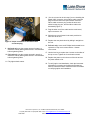
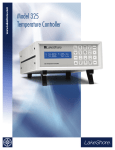
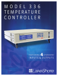
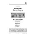
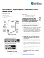
Instructions, Input Option Card Installation, Model 306X FIELD INSTALLATION Input option card kit: (1) 14-conductor ribbon cable (1) Option card Required tools: Small Phillips-head screwdriver 5/64-inch hex key (included) CAUTION: The components on this board are electrostatic discharge sensitive (ESDS) devices. Wear shock-proof wrist straps (resistor limited to <5 mA) to prevent injury to service personnel and to avoid inducing an electrostatic discharge (ESD) into the device. NOTE: The Model 3060 can be installed in a half rack or full rack instrument. All other option cards can only be installed in full rack instruments. 1. Half rack only: Remove the two screws used to attach the ceramic block to the full-rack adapter plate; set aside the screws, and discard full-rack adapter plate. 2. Turn instrument power switch OFF. Unplug the power cord from the wall outlet, then from the instrument. Figure 1. Cover screws 3. Stand the unit on its face. Use the hex key to remove the 4 screws (2 on each side) of the top cover. Loosen the 2 rear bottom screws (Figure 1). 4. Full rack only: use a small Phillips screwdriver to remove the 2 top cover screws and 1 rear bottom screw (Figure 1). 5. Remove the rear plastic bezel. The cover is tracked. Slide the top cover to the rear on the track to remove it. 6. Remove the rear panel option plate screws and set them aside (Figure 2). Remove the rear panel option plate. 7. With the instrument still standing on its face, turn it to view the circuit board inside. Figure 2. Option plate screws 8. From inside the instrument, place the option card into its position in the rear panel. Orient the card so that the 14-pin ribbon cable connector is toward the bottom of the instrument, closest to the main circuit board (Figure 3). Lake Shore Cryotronics, Inc. 575 McCorkle Blvd Westerville, Ohio 43082 Tel: (614) 891-2244 Fax: (614) 818-1600 e-mail: [email protected] www.lakeshore.com F010-09-00 Revision E 1 May 2014 12. (You do not need to do this step if you are installing the Model 3062.) Insert the 14-pin ribbon cable connector plug into the socket on the option board. Orient the ribbon cable connector plug so that the arrow nub slides into the plug slot, and the ribbon cable exits downward (Figure 3). 13. Plug the other end of the cable into the main board, option connector J12. 14. Slide the top cover forward in the track provided on each side of the unit. Figure 3. Proper orientation of the ribbon cable connector plug 9. Half rack only: use the screws removed in step 1 to attach the card by starting both screws in a few threads before tightening either. 10. Full rack only: use the screws removed in step 6 to attach the card by starting both screws in a few threads before tightening either. 15. Replace the rear plastic bezel by sliding it straight into the unit. 16. Full rack only: use a small Phillips head screwdriver to replace the 2 top cover screws and the 1 bottom cover screw. 17. Use the hex key to replace the 4 screws on the sides of the top covers. Tighten the 2 rear bottom screws. 18. Replace the power cord in the rear of the unit and set the power switch to On. 11. Fully tighten both screws. 19. To verify option card installation, check the instrument information by pressing and holding the Escape key. Refer to instrument user’s manual for more information on verifying option card installation. Lake Shore Cryotronics, Inc. 575 McCorkle Blvd Westerville, Ohio 43082 Tel: (614) 891-2244 Fax: (614) 818-1600 e-mail: [email protected] www.lakeshore.com F010-09-00 Revision E 1 May 2014