1
Preface
Overview and definition of
terms
1
______________
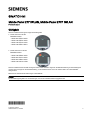
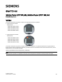
SIMATIC HMI Fail-safe operation of the Mobile Panel 277F IWLAN
Safety instructions,
standards and notes
2
______________
SIMATIC HMI
3
Application Planning
______________
Fail-safe operation of the
Mobile Panel 277F IWLAN
4
Configuration
______________
5
System commissioning
______________
Function Manual
6
Operation
______________
7
Diagnostics
______________
8
Maintenance
______________
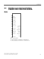
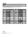
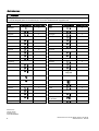
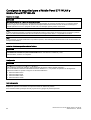
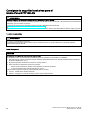
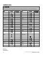
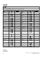
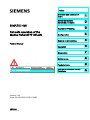
The following supplement is part of this documentation:
No.
Designation
Drawing number
Edition
1
Product Information
A5E02615843-01
08/2009
Version 1.04
Order No. 6AV6691-1FQ01-2AB0
08/2008
A5E01003779-01
9
Technical data
______________
Application example: Safety
Functions
A
______________
Legal information
Legal information
Warning notice system
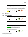
This manual contains notices you have to observe in order to ensure your personal safety, as well as to prevent
damage to property. The notices referring to your personal safety are highlighted in the manual by a safety alert
symbol, notices referring only to property damage have no safety alert symbol. These notices shown below are
graded according to the degree of danger.
DANGER
indicates that death or severe personal injury will result if proper precautions are not taken.
WARNING
indicates that death or severe personal injury may result if proper precautions are not taken.
CAUTION
with a safety alert symbol, indicates that minor personal injury can result if proper precautions are not taken.
CAUTION
without a safety alert symbol, indicates that property damage can result if proper precautions are not taken.
NOTICE
indicates that an unintended result or situation can occur if the corresponding information is not taken into
account.
If more than one degree of danger is present, the warning notice representing the highest degree of danger will
be used. A notice warning of injury to persons with a safety alert symbol may also include a warning relating to
property damage.
Qualified Personnel
The device/system may only be set up and used in conjunction with this documentation. Commissioning and
operation of a device/system may only be performed by qualified personnel. Within the context of the safety notes
in this documentation qualified persons are defined as persons who are authorized to commission, ground and
label devices, systems and circuits in accordance with established safety practices and standards.
Prescribed Usage
Note the following:
WARNING
This device may only be used for the applications described in the catalog or the technical description and only
in connection with devices or components from other manufacturers which have been approved or
recommended by Siemens. Correct, reliable operation of the product requires proper transport, storage,
positioning and assembly as well as careful operation and maintenance.
Trademarks
All names identified by ® are registered trademarks of the Siemens AG. The remaining trademarks in this
publication may be trademarks whose use by third parties for their own purposes could violate the rights of the
owner.
Disclaimer of Liability
We have reviewed the contents of this publication to ensure consistency with the hardware and software
described. Since variance cannot be precluded entirely, we cannot guarantee full consistency. However, the
information in this publication is reviewed regularly and any necessary corrections are included in subsequent
editions.
Siemens AG
Industry Sector
Postfach 48 48
90026 NÜRNBERG
GERMANY
Order-No.: 6AV6691-1FQ01-2AB0
Ⓟ 08/2008
Copyright © Siemens AG 2008.
Technical data subject to change
Preface
Purpose of the function manual
This function manual provides all information required for operation of the Mobile
Panel 277F IWLAN in fail-safe systems.
Readership of this function manual:
● Plant designers
● Project engineers
● Commissioning engineers
● Users
● Service technicians
● Maintenance technicians
Please pay particular attention to the "Safety instructions, standards and notes" chapter.
Basic knowledge required
General knowledge in the field of automation technology, safety technology, and process
communication is a prerequisite for comprehension of this function manual.
It is also assumed that those using the manual have experience in using personal computers
and knowledge of Microsoft operating systems.
Valid scope of the function manual
The function manual covers the Mobile Panel 277F IWLAN HMI device in combination with
the software packages STEP 7 V5.4 SP2 or higher, S7 Distributed Safety V5.4 SP3 and
WinCC flexible 2007 with HSP Mobile Panel 277 Wireless.
Position in the information landscape
This function manual is part of the SIMATIC HMI documentation. The section below provides
an overview of the documentation which is relevant to applications with Mobile
Panel 277F IWLAN.
Additional documentation for Mobile Panel 277F IWLAN
● Operating instructions for Mobile Panel 277F IWLAN
● Mobile Panel IWLAN Getting Started
Fail-safe operation of the Mobile Panel 277F IWLAN
Function Manual, 08/2008, 6AV6691-1FQ01-2AB0
3
Preface
Documentation for fail-safe systems
● System description "Safety technology in SIMATIC S7"
– Provides general information on the use, structure, and mode of operation of the failsafe automation systems S7 Distributed Safety and S7 F/FH Systems
– Contains detailed technical information which can be represented for the fail-safe
technology both in S7-300 and S7-400.
– Contains information about the calculation of monitoring and reaction times of the failsafe systems S7 Distributed Safety and of S7 F/FH Systems.
● "S7 Distributed Safety, Configuring and Programming" Manual / Online Help
Describes the configuration of the F-CPU and of the fail-safe I/O and the programming of
the F-CPU in F-FBD or F-LAD
● "Automation System S7-400, CPU Data" Reference Manual
Describes the standard functions of CPU 416F-3 PN/DP, CPU 414-3 PN/DP and
CPU 416-3 PN/DP
● "Automation System S7-300, CPU Data" Reference Manual
Describes the standard functions of CPU 315F-2 PN/DP, CPU 317F-2 PN/DP,
CPU 315-2 PN/DP and CPU 317-2 PN/DP
User manuals
● WinCC flexible Compact/ Standard/ Advanced
Describes basic principles of configuration using the WinCC flexible Compact
Engineering System/WinCC flexible Standard/WinCC flexible Advanced.
● WinCC flexible Runtime
Describes how to commission and operate your runtime project on a PC.
● Communication
– Communication Part 1 describes the connection of the HMI device to SIMATIC PLCs.
– Communication Part 2 describes the connection of the HMI device to third-party PLCs.
Getting started
● WinCC flexible for first time users
Based on an example project, this is a step-by-step introduction to the basics of
configuring screens, alarms, recipes and screen navigation.
● WinCC flexible for power users
Based on an example project, this is a step-by-step introduction to the basics of
configuring logs, project reports, scripts, user management, multilingual projects and
integration in STEP 7.
● WinCC flexible options
Based on an example project, this is a step-by-step introduction to the basics of
configuring the WinCC flexible Sm@rtServices, Sm@rtAccess and OPC server options.
4
Fail-safe operation of the Mobile Panel 277F IWLAN
Function Manual, 08/2008, 6AV6691-1FQ01-2AB0
Preface
Online availability
The link below guides you to the multilingual technical documentation offered for the
SIMATIC products and systems.
"http://www.automation.siemens.com/simatic/portal/html_76/techdoku.htm"
Screens
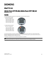
The HMI device is sometimes represented in the form of photographs in this function
manual. The photographs of the HMI device may differ slightly from the factory state of the
HMI device.
Conventions
Configuration and runtime software differ with regard to their names as follows:
● "WinCC flexible 2007" for example, refers to the configuration software.
The term "WinCC flexible" is used in a general context. The full name, for example
"WinCC flexible 2007", is always used when it is necessary to differentiate between
different versions of the configuration software.
● "WinCC flexible Runtime" refers to the runtime software that can run on HMI devices.
The following text notation facilitates the reading of this function manual:
Notation
Scope
"Add screen"
•
•
•
Terminology that appears in the user interface, for example
dialog names, tabs, buttons, menu commands
Inputs required, for example limit values, tag values
Path information
"File > Edit"
Operational sequences, for example menu commands, shortcut
menu commands.
<F1>, <Alt+P>
Keyboard operation
Please observe notes labeled as follows:
Note
Notes contain important information concerning the product, its use or a specific section of
the documentation to which you should pay particular attention.
Trademarks
Names labeled with a ® symbol are registered trademarks of the Siemens AG. Other names
used in this documentation may be trademarks, the use of which by third parties for their
own purposes could violate the rights of the owner.
● HMI®
● SIMATIC®
● SIMATIC HMI®
● SIMATIC ProTool®
● SIMATIC WinCC®
Fail-safe operation of the Mobile Panel 277F IWLAN
Function Manual, 08/2008, 6AV6691-1FQ01-2AB0
5
Preface
Representatives and offices
If you have any further questions relating to the products described in this manual, please
contact your local representative at the Siemens branch nearest you.
Your Siemens representative can be found at "http://www.automation.siemens.com/partner".
Training center
Siemens AG offers a variety of training courses to familiarize you with automation systems.
Please contact your regional training center, or our central training center in 90327
Nuremberg, Germany, for details.
Internet: "http://www.sitrain.com"
Technical support
You can contact Technical Support as follows:
Using the support request form on the web at:
"http://www.siemens.com/automation/support-request"
Further information about our technical support is available on the Internet at
"http://www.siemens.com/automation/service".
Service & Support on the Internet
Service & Support provides additional comprehensive information on SIMATIC products
through online services at "http://www.siemens.com/automation/support":
● The newsletter offers you the latest information about your products
● A large document base is available using our Service & Support search engine
● A forum for global exchange of information by users and experts
● Current product information, FAQs and downloads
● Your local Automation & Drives representative
● Information about on-site services, repairs, spare parts, and more
6
Fail-safe operation of the Mobile Panel 277F IWLAN
Function Manual, 08/2008, 6AV6691-1FQ01-2AB0
Table of contents
Preface ...................................................................................................................................................... 3
1
2
3
4
Overview and definition of terms.............................................................................................................. 11
1.1
Using the Mobile Panel 277F IWLAN ..........................................................................................11
1.2
Areas in the plant .........................................................................................................................12
1.3
Switch-off behavior ......................................................................................................................16
1.4
Integration and segregation .........................................................................................................18
1.5
Log on and log off at the effective range .....................................................................................19
1.6
1.6.1
1.6.2
Safety-oriented operator controls.................................................................................................20
Emergency stop button ................................................................................................................20
Enabling button ............................................................................................................................22
1.7
"Override" mode...........................................................................................................................24
Safety instructions, standards and notes ................................................................................................. 27
2.1
Safety instructions........................................................................................................................27
2.2
Guidelines, standards, certificates and approvals .......................................................................30
2.3
Operating safety...........................................................................................................................33
2.4
Power supply................................................................................................................................34
2.5
Notes about usage.......................................................................................................................36
2.6
Risk analysis ................................................................................................................................37
2.7
Safety functions of the emergency stop button............................................................................37
2.8
Safety functions of the enabling button........................................................................................39
Application Planning ................................................................................................................................ 41
3.1
Check list: Planning the application .............................................................................................41
3.2
Application and ambient conditions .............................................................................................42
3.3
Check list: Planning the system ...................................................................................................45
3.4
Planning effective ranges.............................................................................................................46
3.5
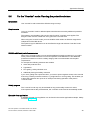
For the "Override" mode: Planning the protective devices ..........................................................49
3.6
Check list: Data security ..............................................................................................................50
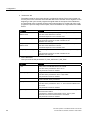
Configuration ........................................................................................................................................... 53
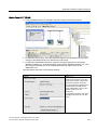
4.1
Check list: Configuration ..............................................................................................................53
4.2
Procedure for configuration..........................................................................................................53
4.3
4.3.1
4.3.2
STEP 7: HW Config .....................................................................................................................55
Integrating the GSD file in STEP 7 ..............................................................................................55
Assigning parameters for communication between the HMI device and the controller...............55
Fail-safe operation of the Mobile Panel 277F IWLAN
Function Manual, 08/2008, 6AV6691-1FQ01-2AB0
7
Table of contents
5
6
7
8
9
8
4.4
4.4.1
4.4.2
4.4.3
4.4.4
S7 Distributed Safety .................................................................................................................. 58
Checklist: Creation of the safety program................................................................................... 59
Using F-FBs ................................................................................................................................ 60
FB161: Mobile Panel Status (F_FB_MP) .................................................................................... 63
FB162: Effective range for 4 Mobile Panel (F_FB_RNG_4) / FB 163 Effective range for 16
Mobile Panel (F_FB_RNG_16).................................................................................................... 67
4.5
4.5.1
4.5.2
4.5.3
WinCC flexible............................................................................................................................. 72
Configuration overview................................................................................................................ 72
Effective ranges editor ................................................................................................................ 73
Objects for the Mobile Panel 277F IWLAN ................................................................................. 73
System commissioning ............................................................................................................................ 77
5.1
Acceptance of the system ........................................................................................................... 77
5.2
Accepting effective ranges and transponders............................................................................. 79
Operation................................................................................................................................................. 83
6.1
Organizational measures ............................................................................................................ 83
6.2
6.2.1
6.2.2
6.2.3
6.2.3.1
6.2.3.2
6.2.3.3
6.2.3.4
6.2.4
6.2.4.1
6.2.4.2
6.2.4.3
6.2.5
6.2.5.1
6.2.6
6.2.6.1
6.2.6.2
6.2.7
6.2.7.1
6.2.7.2
Typical applications..................................................................................................................... 84
Overview ..................................................................................................................................... 84
Switch on the HMI device............................................................................................................ 85
Integrating and segregating the HMI device ............................................................................... 86
Integrating the HMI device (start project).................................................................................... 86
Communication error for the integrated HMI device ................................................................... 87
Discrepancy error during enabling .............................................................................................. 88
Segregate.................................................................................................................................... 90
Log on and log off at the effective range..................................................................................... 91
Detecting the effective range ...................................................................................................... 91
Log on at the effective range ...................................................................................................... 92
Log off at the effective range ...................................................................................................... 93
Behavior in the effective rage ..................................................................................................... 94
Exiting the effective range without log off ................................................................................... 94
"Override" mode.......................................................................................................................... 95
Activating "override" mode .......................................................................................................... 95
Terminating "override" mode....................................................................................................... 96
Special operating conditions ....................................................................................................... 97
Internal error................................................................................................................................ 97
Communication error with the HMI device logged on in the effective range .............................. 98
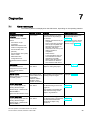
Diagnostics .............................................................................................................................................. 99
7.1
Alarm messages ......................................................................................................................... 99
7.2
Diagnostics................................................................................................................................ 101
Maintenance .......................................................................................................................................... 105
8.1
Function tests............................................................................................................................ 105
8.2
Maintenance cycles................................................................................................................... 105
8.3
Cleaning, repairs and spare parts............................................................................................. 106
Technical data ....................................................................................................................................... 109
9.1
Technical data for fail-safe operation........................................................................................ 109
9.2
HMI device ................................................................................................................................ 111
9.3
Charging station ........................................................................................................................ 112
Fail-safe operation of the Mobile Panel 277F IWLAN
Function Manual, 08/2008, 6AV6691-1FQ01-2AB0
Table of contents
A
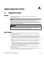
Application example: Safety Functions .................................................................................................. 113
A.1
Configuration and operation.......................................................................................................113
A.2
Components and settings used .................................................................................................116
A.3
Safety program S7 Distributed Safety .......................................................................................121
Index...................................................................................................................................................... 127
Fail-safe operation of the Mobile Panel 277F IWLAN
Function Manual, 08/2008, 6AV6691-1FQ01-2AB0
9
Table of contents
10
Fail-safe operation of the Mobile Panel 277F IWLAN
Function Manual, 08/2008, 6AV6691-1FQ01-2AB0
1
Overview and definition of terms
1.1
Using the Mobile Panel 277F IWLAN
Use
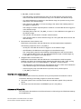
The Mobile Panel 277F IWLAN offers the possibility of having the mobile safety functions of
emergency stop and enable available at any point of a machine or plant. An effective range
limit has been implemented for the Mobile Panel 277F IWLAN. Depending on his location,
the operator obtains a safe, electronically monitored operator control enable.
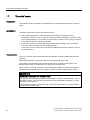
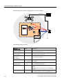
The HMI device communicates with an access point via WLAN. Thus the operator can
operate the various machines or process cells without bothersome cable. The HMI device is
connected via the access point with a PROFINET network in which it communicates with an
F-CPU via the PROFIsafe protocol.
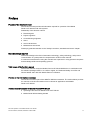
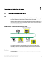
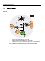
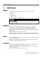
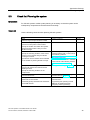
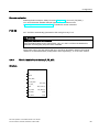
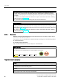
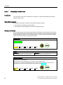
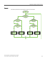
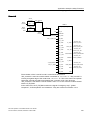
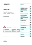
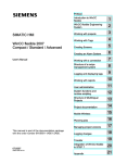
Sample installation - F-system with Mobile Panel 277F IWLAN
6,0$7,&6)31'3DV
352),1(7,2FRQWUROOHU
6
352),1(7
(76
)DLOVDIH,2DV
352),1(7,2GHYLFH
6&$/$1&(
$FFHVV3RLQW
0RELOH3DQHO),:/$1
In the depicted configuration, each PROFINET IO device communicates with a single
PROFINET IO controller. In this example the Mobile Panel 277F IWLAN communicates
exclusively with the F-CPU as F-PROFINET IO controller.
Basic terms
In the following chapters several basic terms are explained that you must learn before you
use the HMI device.
Fail-safe operation of the Mobile Panel 277F IWLAN
Function Manual, 08/2008, 6AV6691-1FQ01-2AB0
11
Overview and definition of terms
1.2 Areas in the plant
1.2
Areas in the plant
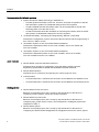
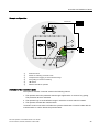
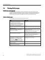
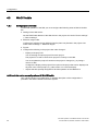
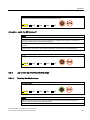
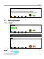
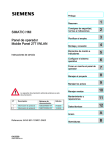
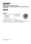
WLAN area
The WLAN area is the area in the plant where the HMI device communicates with other
communication nodes over a wireless local area network.
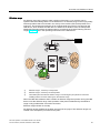
352),VDIH
①
Access point is the network transition from WLAN to LAN
②
WLAN area in which communication with the access point is possible
③
Mobile panel in the WLAN area; the emergency stop button is active, the enabling buttons are
without function.
When the PROFIsafe communication between the controller and operator panel is
established in the WLAN area, the emergency stop button on the HMI device becomes
active.
Safe operation of the plant with the enabling buttons only becomes possible when the HMI
device is logged on in an effective range within the WLAN area.
12
Fail-safe operation of the Mobile Panel 277F IWLAN
Function Manual, 08/2008, 6AV6691-1FQ01-2AB0
Overview and definition of terms
1.2 Areas in the plant
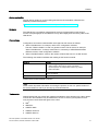
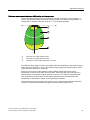
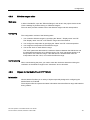
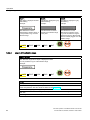
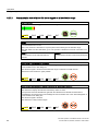
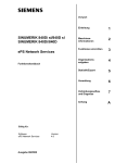
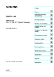
Effective range
An effective range is the range in which sections of the plant, e.g. a machine can be
operated with the enabling buttons of the HMI device. An effective range is formed physically
with transponders that are mounted in the vicinity of the machine. Each transponder has a
unique ID. The transponder emits this ID in a lobe-shaped area. The ID is received by the
HMI device, which enables the HMI device to determine its distance from the transponder.
Additional information about the transponders is provided in the chapter Planning effective
ranges (Page 46) and in the operating instructions for the HMI device.
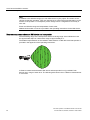
352),VDIH
①
Effective range 1, formed by a transponder
②
Effective range 2, formed by two transponders
③
The mobile panel is located in effective range 3. The emergency stop button is active The
enabling buttons are active after logon in the effective range.
When the HMI device detects that it is within an effective range the operator can log the HMI
device on at the effective range. Safe operation of the plant unit delimited by the effective
range is only possible after successful connection.
Effective ranges should not overlap.
All effective ranges available in the plant are stored in the project. The effective ranges are
verified in the acceptance procedure for the plant.
Fail-safe operation of the Mobile Panel 277F IWLAN
Function Manual, 08/2008, 6AV6691-1FQ01-2AB0
13
Overview and definition of terms
1.2 Areas in the plant
Note
In addition to the effective ranges you can define zones in your project. The zones are not
relevant for fail-safe operation. They are used merely to control the project depending on the
location of the operator. For example a picture change can be configured for zone entry or
zone exit.
Zones and effective range are independent of each other.
Additional information on zones is provided in the Operating instructions for the HMI device.
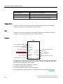
Distance measurement between HMI device and transponder
The transmitting range of the transponder and the receiving range of the HMI device have
the approximate shape of a lobe with a range of approximately 8 m.
The detailed representation of the radiation characteristics of HMI device and transponder is
provided in the appendix of the Operating instructions.
A distance measurement between HMI device and transponder is only possible if both
devices are in range of each other. The following table shows when a distance measurement
is successful.
14
Fail-safe operation of the Mobile Panel 277F IWLAN
Function Manual, 08/2008, 6AV6691-1FQ01-2AB0
Overview and definition of terms
1.2 Areas in the plant
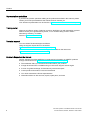
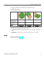
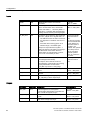
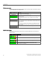
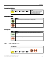
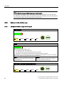
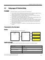
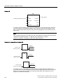
In the figures the HMI device and transponder are represented as follows:
● The HMI device as circle
● The transponder as square
HMI device in the
transmitting range of
the transponder
Yes
Yes
No
Transponder in the
receiving range of the
HMI device
Yes
No
Yes
Successful distance
measurement
Distance measurement
not possible
Distance measurement
not possible
Result
The distance measurement is executed in the following manner:
● The HMI device emits signals in the current project.
● The transponder reacts to the signal from the HMI device and transmits its ID to the HMI
device.
● The HMI device evaluates the ID and only measures the distance to the configured
transponders.
See also
Integration and segregation (Page 18)
Planning effective ranges (Page 46)
Fail-safe operation of the Mobile Panel 277F IWLAN
Function Manual, 08/2008, 6AV6691-1FQ01-2AB0
15
Overview and definition of terms
1.3 Switch-off behavior
1.3
Switch-off behavior
Introduction
Different switch-off behavior is possible depending on the situation in the plant:
● Emergency stop
● Shutdown
● Local rampdown.
● Global rampdown
Plant switch-off differs in its triggers and effects.
DANGER
No switch off triggering
In the plant the described switch-off behavior is only triggered if the F-CPU has been
programmed accordingly.
Emergency stop
The operator triggers the emergency stop by pressing the emergency stop button.
Emergency stop is a procedure in response to an emergency that is intended to stop a
process or movement that could result in danger (from EN 60204-1 Appendix D).
The emergency stop immediately stops all machines that are assigned to the F-CPU via the
safety program.
The emergency stop depends on the effective ranges.
The emergency stop button is always active if there is PROFIsafe communication between
HMI device and F-CPU, i.e. if the HMI device is integrated in the PROFIsafe communication.
Shutdown
Shutdown is triggered if the F-CPU detects a communication error on an HMI device which is
logged on in the effective range.
Shutdown is the immediate stopping of the machines which belong to the effective range.
The shutdown is always specific to the effective range.
Local rampdown.
Local rampdown is triggered if the HMI device is logged on at the effective range and if it is
removed from the effective range for longer than 30 seconds.
Local rampdown is the defined shutdown of the machines belonging to the effective range
within a defined time period.
Local rampdown is always specific to the effective range.
16
Fail-safe operation of the Mobile Panel 277F IWLAN
Function Manual, 08/2008, 6AV6691-1FQ01-2AB0
Overview and definition of terms
1.3 Switch-off behavior
Global rampdown
Global rampdown is triggered if the F-CPU detects a communication error on an HMI device
which is integrated in the PROFIsafe communication.
Global rampdown is the defined shutdown of the machines assigned in the safety program
within a defined time period.
Global rampdown is independent of the effective ranges.
In the safety program of the F-CPU, ensure that global rampdown is available in the event
that a communication error occurs on an HMI device which is integrated in the PROFIsafe
communication.
Trigger
The switch off can have the following triggers:
● The operator presses the emergency stop button.
● A communication error occurs.
● Timeout: The HMI device is logged on at the effective range and the operator leaves the
effective range with his HMI device for longer than 30 seconds.
Triggering the switch off
The following table shows the effect of the different triggers depending on the operating
situation:
Operating situation
Trigger
HMI not integrated
HMI
integrated
HMI device logged on
at the effective range
Emergency stop
pressed
Communication
error
Timeout
---
---
---
HMI device is in the
effective range
Emergency stop
Shutdown
---
HMI device is outside of the
effective range for less than
30 seconds
Emergency stop
Shutdown
---
HMI device is outside of the
effective range for longer
than 30 seconds
Emergency stop
Shutdown
Local
rampdown.
Emergency stop
Global
rampdown
---
HMI device is logged off from the effective range
Fail-safe operation of the Mobile Panel 277F IWLAN
Function Manual, 08/2008, 6AV6691-1FQ01-2AB0
17
Overview and definition of terms
1.4 Integration and segregation
1.4
Integration and segregation
Introduction
In fail-safe operation a safety program runs in the F-CPU. This safety program
communicates with the HMI device. The F-CPU monitors this communication for errors and
analyzes the signals. The terms "integrate" and "segregate" refer to the integration and
segregation of the HMI device in/from the safety program of the F-CPU.
Integrate
If the HMI device is configured for the safety program then when the HMI device starts it is
automatically integrated in the safety program. The integration process is concluded as soon
as the LED"SAFE" is illuminated.
The emergency stop button is active as soon as the HMI device is integrated.
Segregation
Segregation means the desired segregation of the HMI device from the safety program.
The operator has the following alternatives for segregating the HMI device:
● The operator terminates the project.
● The operator presses the ON/OFF button for longer than 4 seconds. After the
segregation process the HMI device switches off.
When the operator segregates the HMI device there are no side effects, e.g. a global
rampdown. When the segregation process is terminated the LED "SAFE" and the
emergency stop button are no longer active.
See also
Safety functions of the emergency stop button (Page 37)
18
Fail-safe operation of the Mobile Panel 277F IWLAN
Function Manual, 08/2008, 6AV6691-1FQ01-2AB0
Overview and definition of terms
1.5 Log on and log off at the effective range
1.5
Log on and log off at the effective range
Introduction
An effective range is the range within which plant units, e.g. a machine, can be operated with
the enabling buttons of the HMI device. The prerequisite for this is that the operator must log
the HMI device on at the effective range.
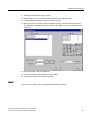
Logging on at the effective range
If the operator enters an effective range with the HMI device the system shows that he can
log the HMI device on at the effective range via the "Effective range name" object.
To log on he touches the "Effective range name" object. Then he reads the effective range
ID in the plant and enters this ID in the ""Effective range logon" dialog box.
If the entered effective range ID agrees with the configured ID then the HMI device is logged
on.
When the HMI device is logged on the enabling buttons are active.
The system alerts the operator that the HMI device is logged on at the effective range in the
following manner:
● The LED "RNG" is illuminated.
● The "Effective range name" object is displayed in green.
● In the process cell the indicator for the effective range is active, e.g. a lamp.
When the HMI device is logged on at the effective range the following rules apply:
● The operator should not leave the effective range without logging off. Local rampdown
occurs if the operator leaves the effective range for longer than 30 seconds without
logging off.
● No other HMI device can log on at this effective range.
Log off at the effective range
Before the operator exits the effective range at which the HMI device is logged on, he must
log off from the effective range. To log off he touches the "Effective range name" object and
edits the dialog box ""Effective range logoff".
When the HMI device is logged off the enabling buttons are no longer active. The
LED "RNG" is not illuminated.
See also
Log on and log off at the effective range (Page 91)
Fail-safe operation of the Mobile Panel 277F IWLAN
Function Manual, 08/2008, 6AV6691-1FQ01-2AB0
19
Overview and definition of terms
1.6 Safety-oriented operator controls
1.6
Safety-oriented operator controls
Introduction
The Mobile Panel 277F IWLAN has the following elements for safe operation of a process
cell:
● Emergency stop button
● Enabling button
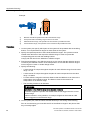
1.6.1
Emergency stop button
Introduction
The emergency stop button is designed with 2-channels and enables an emergency stop of
the configured system.
The emergency stop button satisfies the requirements specified in DIN IEC 60947-5-5;1997
Annex K.
For additional safety instructions please refer to the chapter, Safety instructions, standards
and notes.
When using the emergency stop button the following F-FBs must be linked in the safety
program of the F-CPU:
● F_FB_MP
● F_FB_RNG_n
20
①
Fall protection
②
Emergency stop button
Fail-safe operation of the Mobile Panel 277F IWLAN
Function Manual, 08/2008, 6AV6691-1FQ01-2AB0
Overview and definition of terms
1.6 Safety-oriented operator controls
Due to its position, the emergency stop button is equally accessible for both left-handed and
right-handed individuals.
Due to its profiled design, the emergency stop button is easily accessible. A collared
enclosure is used to protect the operator controls against damage. This applies in particular
to the emergency stop button The emergency stop button may still trigger if the HMI device
falls and hits the floor.
Operation
The operator triggers the emergency stop by pressing the emergency stop button. The
emergency stop button engages in the emergency stop position.
Releasing the emergency stop button
WARNING
If you have activated the emergency stop button and thereby brought the configured
system to a standstill, the emergency stop button should only be released under the
following conditions:
• The reasons for the emergency stop have been eliminated.
• A safe restart is possible.
• The restart should not be executed by releasing the emergency stop button.
The operator must strictly ensure that he executes a separate operator action to
commence the restart. The safety program must ensure that release of the emergency
stop button alone does not trigger an automatic restart of the system.
In order to release the emergency stop button, turn it in a clockwise direction. The
emergency stop button then returns on its own to the initial position.
See also
Safety functions of the emergency stop button (Page 37)
S7 Distributed Safety (Page 58)
Fail-safe operation of the Mobile Panel 277F IWLAN
Function Manual, 08/2008, 6AV6691-1FQ01-2AB0
21
Overview and definition of terms
1.6 Safety-oriented operator controls
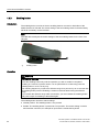
1.6.2
Enabling button
Introduction
The enabling device consists of the two enabling buttons mounted on both sides of the
Mobile Panel 277F IWLAN. The switch setting of the two enabling buttons is determined by
electrical momentary contact switches.
Note
The HMI device analyzes the switch settings of the two enabling buttons in the form of an
OR gate.
①
Enabling button
Operation
WARNING
Unintentional enabling
Press the enabling button only until the operation you wish to enable is completed.
Enabling is a conscious operator action. It is not permissible to continuously press the
enabling button or to fix it in any way.
The following happens if you leave the effective range for a period of up to 30 seconds with
the enabling button pressed: Enabling is revoked 5 seconds after leaving the effective
range.
If you reenter the effective range within 30 seconds, you must release the enabling button
and press it again for enabling to take effect again.
The enabling button has three switch settings:
● Neutral position: The enabling button is not pressed.
● Enable: The enabling button is pressed to a mid position. This switch setting is used to
allow another command, for example an input with the membrane keyboard.
22
Fail-safe operation of the Mobile Panel 277F IWLAN
Function Manual, 08/2008, 6AV6691-1FQ01-2AB0
Overview and definition of terms
1.6 Safety-oriented operator controls
● Panic: The "Panic" switch setting is reached as soon as one of the two enabling buttons
is fully pressed. The switch setting of the other enabling button is unimportant in this
case. The "Panic" switch setting has the same effect as releasing the enabling button,
namely, it revokes the enable.
You only have to activate one enabling button. The PLC gets the same signal regardless as
to whether one or two enabling buttons of the Mobile Panel 277F IWLAN have been
pressed.
Note
The enabling button and the membrane keyboard can be operated at the same time.
When using the enabling button the following F FBs must be linked in the safety program of
the F CPU:
● F_FB_MP
● F_FB_RNG_n
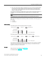
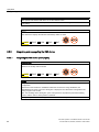
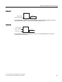
Switch settings
The following figure shows the switching sequence for enable.
1HXWUDOSRVLWLRQ
(QDEOH
[
6ZLWFKVHWWLQJ
(%OHIW(%ULJKW
\
1HXWUDOSRVLWLRQ
[
(%OHIW(%ULJKW
(%(QDEOLQJEXWWRQ
\
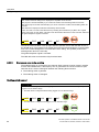
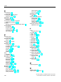
The following figure shows the switching sequence during panic usage.
1HXWUDOSRVLWLRQ
(QDEOH
[
6ZLWFKVHWWLQJ
(%OHIW(%ULJKW
[
(%OHIW(%ULJKW
X
3DQLF
\
1HXWUDOSRVLWLRQ
X
\
(%(QDEOLQJEXWWRQ
If the operator has pressed the enabling button through to the "Panic" setting, the "Enable"
setting will not be evaluated when leaving the panic setting. A new enable can only be
triggered by releasing the enabling button.
See also
Safety functions of the enabling button (Page 39)
S7 Distributed Safety (Page 58)
Fail-safe operation of the Mobile Panel 277F IWLAN
Function Manual, 08/2008, 6AV6691-1FQ01-2AB0
23
Overview and definition of terms
1.7 "Override" mode
1.7
"Override" mode
Introduction
The effective range functionality of the HMI device can be extended through the "override"
mode.
Applications
"Override" mode can be used in the following cases:
● Use of existing protective measures instead of the effective range functionality
If protective measures, such as protective fences are already available in your plant, then
you can integrate them in your safety concept with the "override" mode. Thus you achieve
a consistent concept for safe plant operation.
● If plant units, which do not allow themselves transponder coverage, (such as inside a
robot cell), will be operated with the enabling buttons.
In this case you must secure the plant area with additional protective measures, such as
a protective fence.
Requirements
Only use "override" mode in delimited plant units that are secured by additional protective
measures.
Entering and leaving the protected area must be monitored by the F-CPU.
The operator must be able to fully see the area for which "override" mode applies. The
danger location must be visible from every point of the override area.
When using the "override" mode you must install a switch within an effective range that is
independent of the HMI device. The operator activates "override" mode with this switch.
WARNING
Inadmissible activation of the "override" mode
The operator has to activate "override" mode through a conscious operator action, e.g. by
activating a switch. The "override" mode should not be automatically activated, e.g. when
the safety area is entered.
The application program in conjunction with F-FB must ensure that the "override" mode is
revoked when the area is left.
24
Fail-safe operation of the Mobile Panel 277F IWLAN
Function Manual, 08/2008, 6AV6691-1FQ01-2AB0
Overview and definition of terms
1.7 "Override" mode
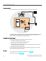
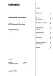
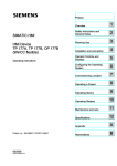
Sample configuration
352),VDIH
①
Protective fence
②
Switch for activating "override" mode
③
Transponder for logging on at the effective range
④
Foot grating for access monitoring
⑤
HMI device
⑥
Machine that will be operated
Activation of the "override" mode
The operator activates "Override" mode in the following manner:
1. The operator enters the protected area through a light barrier or across a foot grating.
The protective device is activated.
2. The operator logs on at the effective range in which the override switch is located.
3. The operator activates the override switch.
"Override" mode is now active until either the operator deactivates "Override" mode with the
override switch or until he leaves the protected area.
Fail-safe operation of the Mobile Panel 277F IWLAN
Function Manual, 08/2008, 6AV6691-1FQ01-2AB0
25
Overview and definition of terms
1.7 "Override" mode
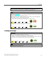
Operating principle
In the following figure you see the plant area for which "override" mode is active.
352),VDIH
If "override" mode is activated the operator can safely operate the associated plant area with
the enabling buttons. The HMI device is considered to be permanently logged on in the
effective range, without analyzing the transponder signals.
Deactivation of "override" mode
The operator deactivates "override" mode in the following manner:
1. The operator activates the override switch.
"Override" mode is deactivated by the safety program.
2. The operator logs off from the effective range.
Subsequent logon at this effective range is only possible if the operator has terminated
"override" mode with the override switch.
3. The operator leaves the protected area.
If the operator leaves the protected area without deactivating "override" mode, "override"
mode is deactivated by the safety program.
See also
For the "Override" mode: Planning the protective devices (Page 49)
Configuration and operation (Page 113)
26
Fail-safe operation of the Mobile Panel 277F IWLAN
Function Manual, 08/2008, 6AV6691-1FQ01-2AB0
Safety instructions, standards and notes
2.1
2
Safety instructions
Safety regulations
WARNING
Injury or material damage
Strictly observe all instructions in this document at all times. Otherwise, hazardous
situations can arise or the safety functions integrated in the HMI device can be rendered
ineffective.
Observe the safety and accident prevention instructions applicable to your application in
addition to the safety instructions given in this manual.
Configuration requirements
WARNING
Injury or material damage
The configuration engineer for a machine or system PLC must take precautions to ensure
that an interrupted program can be restarted normally after communication errors, voltage
dips, or power failures.
Dangerous operating modes must not occur, not even temporarily, from the entire
sequence of the user program up to troubleshooting.
Proper use
WARNING
Commissioning of the HMI device is forbidden until it has been absolutely ensured that the
machine which is to be operated with the HMI device complies with Directive 98/37/EC.
Fault-free operation
WARNING
Interference with other systems
When using the HMI device in accordance with DIN EN 13557 you must ensure that the
HMI device does not interfere with other systems at the site, or that other systems do not
interface with the HMI device.
Fail-safe operation of the Mobile Panel 277F IWLAN
Function Manual, 08/2008, 6AV6691-1FQ01-2AB0
27
Safety instructions, standards and notes
2.1 Safety instructions
Safety measures during operation
WARNING
Non-functional emergency stop button
The emergency stop button must be checked annually for proper function.
WARNING
HMI device failure
After a hard impact to the HMI device, check the safety-relevant features for functional
capability, for example in the event that the HMI device is dropped.
WARNING
Danger of injury
Manual movements controlled with the HMI should only be executed in conjunction with the
enabling buttons and at reduced velocity.
WARNING
Exclusive operating right
When operating the plant with the HMI device it is not permitted to operate the plant
concurrently from a different HMI device.
Prevent concurrent operation through appropriate configuration.
High frequency radiation
WARNING
Unintentional operating situations
High-frequency radiation, for example from cellular phones, can lead to undesirable
operating situations.
28
Fail-safe operation of the Mobile Panel 277F IWLAN
Function Manual, 08/2008, 6AV6691-1FQ01-2AB0
Safety instructions, standards and notes
2.1 Safety instructions
Information for handling the battery:
CAUTION
Charging and discharging the battery
In the following cases, there is a risk of fire and, in extreme cases, explosion!
• Incorrect charging and discharging of the battery
• Reverse polarity
• Short-circuit
Only charge the bridging battery in the HMI device.
Only charge the main battery in the HMI device or in the charging compartment of the
charging station.
CAUTION
The battery is a lithium ion battery. The following safety notes apply to these rechargeable
batteries:
• Do not crush
• Do not expose to heat and do not burn
• Do not short-circuit
• Do not take apart
• Do not immerse in liquid – the battery might crack or burst
• Store unused batteries away from the following items, which can cause the contacts to
be bridged
– Paper clips
– Coins
– Keys
– Nails
– Screws or other small metal objects
CAUTION
Danger of injury
If used incorrectly, fluid can leak from the battery. Avoid contact with the battery fluid. If fluid
comes into contact with the skin, rinse with water.
If fluid comes into contact with the eyes, rinse with water and seek medical advice.
Fail-safe operation of the Mobile Panel 277F IWLAN
Function Manual, 08/2008, 6AV6691-1FQ01-2AB0
29
Safety instructions, standards and notes
2.2 Guidelines, standards, certificates and approvals
Instructions for battery replacement in Mobile Panel 277F IWLAN
CAUTION
Local rampdown of logged on HMI device
If the HMI device which is logged on at the effective range no longer recognizes the
transponder and, therefore, the effective range, it triggers a local rampdown.
To change the battery, rest the HMI device on its front. Align the HMI device so that it is still
possible to measure the distance between the HMI device and the transponder.
If possible, log the HMI device off from the effective range.
NOTICE
Pay attention to cleanliness. Foreign bodies or liquids must not come into contact with the
printed circuit board or penetrate the inside of the HMI device.
Place the HMI device with the front side facing down on a flat, clean surface to protect
against damage.
CAUTION
Malfunctions
If the HMI device is resting on its front, the following can be activated:
• The emergency stop button
This can bring the system to a standstill unintentionally.
• The key-operated switch or an illuminated pushbutton
This can result in malfunctions.
Components and modules endangered by electrostatic discharge (ESD)
When working in the open housing, ensure that current-carrying conductors do not come
into contact with electrical circuits.
Note the ESD instructions.
2.2
Guidelines, standards, certificates and approvals
Certifications
CAUTION
The following overview shows possible approvals.
The only valid approvals for the HMI device, the charging station, the power supply module,
and the transponder are those shown on the label on the rear panel.
30
Fail-safe operation of the Mobile Panel 277F IWLAN
Function Manual, 08/2008, 6AV6691-1FQ01-2AB0
Safety instructions, standards and notes
2.2 Guidelines, standards, certificates and approvals
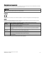
CE approval
The HMI device, charging station, power supply unit, and transponder satisfy the
requirements and protection objectives of the EC Directives below. The HMI device,
charging station, power supply unit, and transponder comply with the harmonized European
standards (EN) published in the Official Journals of the European Union for programmable
controllers:
● 2004/108/EC Electromagnetic Compatibility Directive (EMC Directive)
● 98/37/EG Directive of the European Parliament and Council of 22 June 1998 on the
approximation of the laws and administrative regulations of the Member States
concerning machinery
● Specific absorption rate in accordance with EN 50392
EC Declaration of Conformity
The EC Declarations of Conformity are available to the relevant authorities at the following
address:
Siemens AG
Industry Sector
I IA AS RD ST PLC
PO Box 1963
D-92209 Amberg
UL approval
Underwriters Laboratories Inc., to
● UL 508 (Industrial Control Equipment)
● CSA C22.2 No. 142 (Process Control Equipment)
The approval is only valid in the case of battery operation or when stationary in the charging
station.
Marking for Australia
N117
The HMI device, charging station, power supply unit, and transponder satisfy the
requirements of Standard AS/NZS 2064 (Class A).
Wireless approval
The HMI device wireless approvals for the various countries are located as follows:
● On the rear of the HMI device
● In the product information supplied together with the HMI device
Fail-safe operation of the Mobile Panel 277F IWLAN
Function Manual, 08/2008, 6AV6691-1FQ01-2AB0
31
Safety instructions, standards and notes
2.2 Guidelines, standards, certificates and approvals
TÜV
The TÜV confirms that the HMI device satisfies the requirements of the standards below with
regard to its safety functions.
● SIL3 to IEC 61508-1 to 4
● Category 4 in accordance with EN 954-1.
● Pl e and Cat. 4 in accordance with EN ISO 13849-1
● EN 60204-1
● ISO 13850
● IEC 62061
Requesting certificates
Copies of the certificates and associated reports can be requested from the following
address:
Siemens AG
Industry Sector
I IA AS RD ST
PO Box 1963
D-92209 Amberg
32
Fail-safe operation of the Mobile Panel 277F IWLAN
Function Manual, 08/2008, 6AV6691-1FQ01-2AB0
Safety instructions, standards and notes
2.3 Operating safety
2.3
Operating safety
Standards
The HMI device complies with the following standards:
● EN 954-1
Safety of machinery
● EN 60204-1
Safety of machinery – Electrical equipment of machines
● EN 62061
Safety of machinery – Functional safety of safety-related electrical, electronic and
programmable electronic control systems
● EN ISO 13849-1
Development, testing and certification of safety-related machine controls
● ISO 13850
Safety of machinery – Emergency stop – Principles for design
● IEC 61508
Functional safety of electrical/electronic/programmable electronic-related systems
● EN 61131-1 and EN 61131-2
Programmable Controllers
● The HMI device was tested for EMC in accordance with the following standards:
– EN 61000-6-4, Generic standard – emitted interference
– EN 61000-6-2, Generic standard, Immunity, industrial environments
– EN 61131-2, Programmable Controllers
● EN 300 328 V1.6.1, EN 300 440-1 V1.3.1, EN 301 893, EN 301 489-1, EN 301 489-17,
FCC Part 15.245, 15.247, 15.407
Wireless approval
● EN 50 360, IEEE 1528-X, EN 50371, EN 50 392
Radiation protection requirements (SAR/EMF)
If the HMI device is used in a system, the following standards are fulfilled:
● prEN 1921, Industrial automation systems – safety of integrated manufacturing systems
● EN 12417:2001, Machine tools – safety – machining centers
● UL 508, Industrial Control Equipment
● CSA C22.2 No.14, Industrial Control Equipment
Fail-safe operation of the Mobile Panel 277F IWLAN
Function Manual, 08/2008, 6AV6691-1FQ01-2AB0
33
Safety instructions, standards and notes
2.4 Power supply
2.4
Power supply
Safety specifications
CAUTION
Damage to the HMI device
Only operate the HMI device with approved components:
• Batteries
• Charging station
• For office environments only: Tabletop power supply unit
Order information of the components is available on the Internet at
"http://mall.automation.siemens.com".
WARNING
Injury or material damage
You may operate the HMI device in the plant only with the battery or in the charging station.
Operation with the desktop power supply module is not permitted.
WARNING
Effectiveness of the emergency stop button
The emergency stop button only has an effect if the HMI device is integrated into the safety
program.
Charging station
WARNING
Injury or material damage
The charging station complies with the following standards:
• EN 50335-2-29
• DIN EN 60204-1
• Protection class III in accordance with EN 61131-2 or EN 50178.
The 24 VDC power supply must be ensured by safely isolating the low voltage from
hazardous voltages, e.g. by using a safety transformer or equivalent equipment.
Allowance should be made for the loss of voltage on the connection cable during
dimensional analysis of the supply!
34
Fail-safe operation of the Mobile Panel 277F IWLAN
Function Manual, 08/2008, 6AV6691-1FQ01-2AB0
Safety instructions, standards and notes
2.4 Power supply
WARNING
Injury or material damage
Configure the 24 VDC supply for the charging station correctly, otherwise components of
your automation system can be damaged and persons may be injured.
Use only voltage generated as protective extra-low voltage (PELV) for the 24 VDC supply
of the charging station.
CAUTION
Safe electrical separation
Use only power supply units with safety isolation complying with IEC 60364-4-41 or
HD 384.04.41 (VDE 0100, Part 410), for example according to the PELV standard, for the
charging station's 24 VDC supply.
The supply voltage must be within the specified voltage range. Malfunctions in the charging
station may otherwise result.
Applies to non-isolated system design:
Connect the connection for GND 24 V from the 24 V power supply output to equipotential
bonding for uniform reference potential.
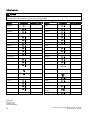
The following table shows the technical data of the supply voltage for the charging station:
Nominal voltage
+24 VDC
Range, permissible
19.2 V to 28.8 V (–20 %, +20 %)
Transients, maximum permissible
35 V (500 ms)
Time between two transients, minimum
50 sec
Current consumption with Mobile Panel
• Typical
• Constant current, maximum
• Power on current surge I2t
•
•
•
Approximately 1.5 A
Approx. 1.8 A
Approx. 1.7 A2s
Current consumption with Mobile Panel and batteries in
charging compartment
• Typical
• Constant current, maximum
• Power on current surge I2t
•
•
•
Approximately 2.8 A
Approximately 3.4 A
Approximately 1.7 A2s
Fuse, internal
Electronic
Connection to the supply voltage
Wire the supply voltage to the cable terminal box included with the charging station using a
3-wire flexible cable (0.75 mm²). For additional information, refer to the operating instructions
of the HMI device.
Fail-safe operation of the Mobile Panel 277F IWLAN
Function Manual, 08/2008, 6AV6691-1FQ01-2AB0
35
Safety instructions, standards and notes
2.5 Notes about usage
Tabletop power supply unit
CAUTION
Please note that the mains connector must be removed for a complete disconnection from
the mains.
Do not operate the HMI device in the plant with the table power supply unit.
The tabletop power supply unit is only suitable for an office environment.
The device is designed for operation on grounded power supply networks (TN systems to
VDE 0100, Part 300, or IEC 364-3).
Operation is not authorized on ungrounded or impedance-grounded power networks
(IT networks).
2.5
Notes about usage
Using the HMI device
A list indicating the country or geographical region of a country in which the HMI device is
certified is included in the product information supplied with the HMI device.
Use in industry
The HMI device is designed for industrial use. For this reason, the following standards are
met:
● Interference emission requirements, paragraph 7.3, DIN EN 60947-1, Environment A
● Interference immunity requirements DIN EN 61326
Residential use
Note
The HMI device is not suitable for use in residential areas: If you use the HMI device in
residential areas, the radio/TV reception may be impeded.
If the HMI device is used in a residential area, you must take measures to achieve Limit
Class B conforming to EN 55011 for RF interference.
A suitable measure for achieving the required RF interference level for Limit Class B
includes for example:
● Use of filters in electrical supply lines
Individual acceptance is required.
36
Fail-safe operation of the Mobile Panel 277F IWLAN
Function Manual, 08/2008, 6AV6691-1FQ01-2AB0
Safety instructions, standards and notes
2.6 Risk analysis
Use of cable-free control equipment
WARNING
When using cable-free control equipment you must ensure that it does not interfere with
other systems at the site, or that other systems do not interfere with it.
2.6
Risk analysis
Carrying out a risk analysis
The following standards must be used to perform the risk analysis:
● EN ISO 12100-1 and EN ISO 12100-2, General design guidelines for machines
● EN 1050 Risk Assessment for Machinery
● EN 954-1 Safety of Machinery
These considerations result in a safety category (B, 1, 2, 3, 4) in accordance with EN 954-1
that ultimately dictates how the safety-related aspects of the system that will be configured
must be furnished.
With the safety-related parts of the Mobile Panel 277F IWLAN the following requirements are
satisfied:
● Category 4 in accordance with EN 954-1.
● SIL 3 in accordance with IEC 61508
● Pl e and Cat. 4 in accordance with EN ISO 13849-1
The risk assessment must take into account that the overall concept of the plant must be
configured accordingly. More detailed instructions on risk assessment and risk reduction are
provided in the system manual "Safety Integrated".
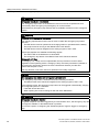
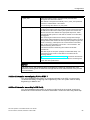
2.7
Safety functions of the emergency stop button
Safety instructions
There is an emergency stop button on the Mobile Panel 277F IWLAN.
The emergency stop button on the Mobile Panel 277F IWLAN brings about a safety-related
stop of the configured machine in accordance with EN 60204-1:1997, Section 9.2.5.3. You
have the option of implementing a Category 0, 1, or 2 Stop function in accordance with
EN 60204-1: 1997, Section 9.2.2. The stop function category must be selected on the basis
of a risk assessment.
Fail-safe operation of the Mobile Panel 277F IWLAN
Function Manual, 08/2008, 6AV6691-1FQ01-2AB0
37
Safety instructions, standards and notes
2.7 Safety functions of the emergency stop button
WARNING
Emergency stop button not available
The emergency stop button on the HMI device must not used as a replacement for a
permanently-wired emergency stop/emergency off on the machine.
Install stationary emergency stop buttons that are available at all times on the configured
system.
WARNING
Effectivity of the emergency stop button
The following requirements must be met in order to render the emergency stop button
effective:
• The HMI device must be operated in the charging station or operated with the battery.
• The project must be running on the Mobile Panel 277F IWLAN.
• The HMI device must be integrated in the safety program of the F-CPU.
If these prerequisites are satisfied the following applies:
• The SAFE LED on the HMI device is illuminated.
• The emergency stop button of the Mobile Panel 277F IWLAN is effective.
Category 0 or 1 Stop
If a Category 0 or 1 Stop circuit is implemented, the stop function must be in effect
regardless of the operating mode. A Category 0 Stop must have precedence. Release of
the emergency stop button should not cause a hazardous situation (see also EN
60204:1997 chapter 9.2.5.3).
The stop function is not to be used as a replacement for safety equipment.
NOTICE
The emergency stop button can be triggered unintentionally
The emergency stop button is evaluated under the following conditions:
• The Mobile Panel 277F IWLAN is integrated in the safety program of the F CPU.
In the following cases, the emergency stop button can be triggered unintentionally, bringing
the configured system to a standstill:
• If the HMI device falls down
• When opening one of the coverings on the rear of the HMI device
WARNING
Emergency stop button disabled
If a global rampdown has been triggered by a communication error, the emergency stop will
no longer be available on the Mobile Panel in question.
You have the option of configuring the "Global rampdown" signal to trigger an emergency
stop.
38
Fail-safe operation of the Mobile Panel 277F IWLAN
Function Manual, 08/2008, 6AV6691-1FQ01-2AB0
Safety instructions, standards and notes
2.8 Safety functions of the enabling button
Storing the HMI device
WARNING
Non-functional emergency stop button
If the HMI device is not integrated, the emergency stop button does not function.
To avoid confusion between effective and non-effective emergency stop buttons, only one
integrated HMI device should be freely accessible.
If the HMI device is not in use, it must be stored in an secure place.
See also
Emergency stop button (Page 20)
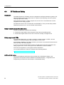
2.8
Safety functions of the enabling button
Introduction
The enabling mechanism is comprised of two enabling buttons mounted on both sides of the
HMI device.
Numerically controlled machines and systems are equipped with the operating modes
"Automatic mode" and "Special mode".
Safety is ensured in automatic mode by means of closed, isolating protective devices and/or
with functional non-isolating protective devices that block access.
In special mode, safety has to be ensured in a different manner than in automatic mode. In
special mode, the danger zones of the machine or system are entered, where controlled
movements have to be possible.
Special mode
A reduced speed on the machine or in the system has to be specified for special mode
based on the risk assessment. Movement of the machine should only be possible when the
enabling device is activated. The operator must have the necessary qualifications and be
acquainted with the details of the intended application.
Safety instructions
The safety-related aspects of the velocity reduction control and those for the enabling device
are designed in such a way that they satisfy the EN 954-1 safety category determined by the
risk analysis.
The operating principles of enabling devices are described in EN 60204. Through the
findings from accident investigations and the existence of technical solutions, the 3-stage
enabling button became state of the art. Positions 1 and 3 of the enabling button are Off
functions. Only the middle position allows the enabling function. EN 60204-1:1997 is
identical to IEC 60204-1, whereby the 3-stage enabling button is gaining international
importance.
Fail-safe operation of the Mobile Panel 277F IWLAN
Function Manual, 08/2008, 6AV6691-1FQ01-2AB0
39
Safety instructions, standards and notes
2.8 Safety functions of the enabling button
The Stop category of the enabling device must be selected on the basis of a risk assessment
and correspond to a Category 0 or 1 Stop.
WARNING
Injury or material damage
Enabling buttons should only be used when the following applies for the person activating
the enabling button:
• The person can see the danger zone.
• The person is capable of recognizing personal injury hazards in good time.
• The person is capable of taking immediate measures to avoid danger.
The only person allowed to remain in the danger zone is the person who is activating the
enabling button.
Commands for unsafe conditions are not permitted to be issued with one enabling button
alone. For this purpose, a secondary, intentional start command by means of a button on
the Mobile Panel 277F IWLAN is required.
The following happens if you leave the effective range for a period of up to 30 seconds with
the enabling button pressed: Enabling is revoked 5 seconds after leaving the effective
range.
If you reenter the effective range within 30 seconds, you must release the enabling button
and press it again for enabling to take effect again.
NOTICE
Enabling button not effective
The enabling button is only effective if the HMI device is logged on in the effective range
and the "RNG" LED on the HMI device lights up.
If the operator leaves the effective range, the enabling button is deactivated after 5
seconds. The "Exit effective range without logoff" dialog opens after 30 seconds. The
"RNG" LED only goes off when the operator confirms this dialog.
Risk from improper use
To avoid the danger of unauthorized use of the enabling button due to impermissible holddown, on each project start the enabling button must be pressed all the way down, and then
released.
See also
Enabling button (Page 22)
40
Fail-safe operation of the Mobile Panel 277F IWLAN
Function Manual, 08/2008, 6AV6691-1FQ01-2AB0
3
Application Planning
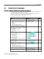
3.1
Check list: Planning the application
Application planning
For application planning of the HMI device go through the following steps.
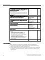
Check list for application planning
Step
Information
Check the application conditions and
environmental conditions
Application and ambient conditions
(Page 42)
Plant planning for application of the HMI device
Check list: Planning the system
(Page 45)
Planning the effective ranges
Planning effective ranges (Page 46)
Only for the "override" mode: Planning the
protective devices
For the "Override" mode: Planning the
protective devices (Page 49)
Planning measures to increase data safety
Check list: Data security (Page 50)
Fail-safe operation of the Mobile Panel 277F IWLAN
Function Manual, 08/2008, 6AV6691-1FQ01-2AB0
Check
41
Application Planning
3.2 Application and ambient conditions
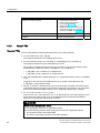
3.2
Application and ambient conditions
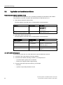
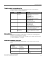
Mechanical and climatic conditions of use
The HMI device is designed for use in a location protected from the effects of the weather.
The conditions of use are compliant with requirements to DIN IEC 60721-3-3:
● Class 3M3 (mechanical requirements)
The table applies to the HMI device, charging station, and transponder.
Tested for
Test standard
Comments
Sinusoidal vibration, stationary
DIN IEC 60721-3-3
Frequency range:
2 ≤ f ≤ 200 Hz
Deflection:
1.5 mm/5 m/s2
Shocks, non-stationary,
Total shock response spectrum
DIN IEC 60721-3-3
Shock amplitude: 70 m/s2
Shock duration: 22 ms
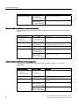
● Class 3K3 (climatic requirements)
The table applies to the HMI device, charging station, and transponder.
Ambient conditions
Permitted range
Air temperature
5 to 40 °C
Relative humidity
5 to 85 %,
no condensation
Absolute humidity
1 to 25 g/m3
Atmospheric pressure
70 to 106 kPa
Comments
Corresponds to relative humidity, load
degree 2 in accordance with
IEC 61131, part 2
Corresponds to an elevation of up to
3,000 m
Use with additional measures
In the following cases the use of the HMI device requires additional measures:
● In locations with a high degree of ionizing radiation
● In locations with difficult operating conditions, for example due to:
– Corrosive vapors, gases, oils or chemicals
– Electrical or magnetic fields of high intensity
● In systems that require special monitoring, for example:
– Elevators
– Systems in especially hazardous rooms
42
Fail-safe operation of the Mobile Panel 277F IWLAN
Function Manual, 08/2008, 6AV6691-1FQ01-2AB0
Application Planning
3.2 Application and ambient conditions
Testing for mechanical environmental conditions
The following table provides information on the type and scope of tests to determine
mechanical ambient conditions for the HMI device.
Tested for
Test standard
Comments
Vibrations
IEC 60068, part 2–6
(sinusoidal)
Type of vibration:
20 frequency cycles with a tuning rate of
1 octave/minute.
Frequency range:
10 ≤ f ≤ 150 Hz, ± 1 Hz
Deflection:
0.35 mm / 5 g ± 15% at the control point
Shock
IEC 60068, part 2–27
Shock form: Half-sinus
Shock amplitude: 30 g
Shock duration: 11 ms
Number of shocks: 3 per axis
Continuous shocks IEC 60068, part 2–29
Shock form: Half-sine
Shock amplitude: 10 g
Shock duration: 16 ms
Shock cycle: (1–3)/s
Number of shocks: 1000 ± 10
Impact
IEC 60068, part 2–75
One-time impact stress of 1 Nm with an impact
test device similar to DIN VDE 0740, Part 1,
Section 19.2 at room temperature.
Falling
Drop testing in accordance
with
EN 60068-2-32
1.2 m
Applies to the HMI device with and without
battery:
Reducing vibrations
If the HMI device is subjected to greater shocks or vibrations, you must take appropriate
measures to reduce acceleration or amplitudes.
We recommend fitting the charging station of the HMI device to vibration-absorbent material
(on metal shock absorbers, for example).
Climatic ambient conditions for the HMI device
The following table shows the permitted climatic ambient conditions for use of the HMI
device:
Ambient conditions
Permitted range
Temperature
• Operation
• Storage/transport
•
•
Comments
0 to 40 °C
–20 to 60 °C
Relative humidity
5 to 85 %,
no condensation
Corresponds to relative humidity, load
degree 2 in accordance with IEC 61131,
part 2
Atmospheric pressure
1060 to 700 hPa
Corresponds to an elevation of –1,000 to
2,000 m
Fail-safe operation of the Mobile Panel 277F IWLAN
Function Manual, 08/2008, 6AV6691-1FQ01-2AB0
43
Application Planning
3.2 Application and ambient conditions
Ambient conditions
Permitted range
Comments
Pollutant concentration
SO2: < 0.5 vpm;
Relative humidity <
60 %, no condensation
Check: 10 cm3/m3; 10 days
H2S: < 0.1 vpm;
Relative humidity <
60 %, no condensation
Check: 1 cm3/m3; 10 days
Climatic ambient conditions for the charging station
The following table shows the permitted climatic ambient conditions for use of the charging
station.
Ambient conditions
Permitted range
Temperature
• Operation
• Storage/transport
•
•
Comments
From 0 to 40 °C
From –20 to 60 °C
Relative humidity
5 to 85 %,
no condensation
Corresponds to relative humidity, load degree 2
in accordance with IEC 61131, part 2
Atmospheric pressure
1060 to 700 hPa
Corresponds to an elevation of –1,000 to
2,000 m
Pollutant concentration
SO2: < 0.5 vpm;
Relative humidity <
60 %, no condensation
Check: 10 cm3/m3; 10 days
H2S: < 0.1 vpm;
Relative humidity <
60 %, no condensation
Check: 1 cm3/m3; 10 days
Ambient climatic conditions for the transponder
The following table shows the permitted climatic ambient conditions for use of the
transponder:
44
Ambient conditions
Permitted range
Temperature
• Operation
• Storage/transport
•
•
Comments
0 to 50 °C
–20 to 60 °C
Relative humidity
5 to 85 %,
no condensation
Corresponds to relative humidity, load degree 2
in accordance with IEC 61131, part 2
Atmospheric pressure
1060 to 700 hPa
Corresponds to an elevation of –1,000 to
2,000 m
Pollutant concentration
SO2: < 0.5 vpm;
Relative humidity <
60 %, no condensation
Check: 10 cm3/m3; 10 days
H2S: < 0.1 vpm;
Relative humidity <
60 %, no condensation
Check: 1 cm3/m3; 10 days
Fail-safe operation of the Mobile Panel 277F IWLAN
Function Manual, 08/2008, 6AV6691-1FQ01-2AB0
Application Planning
3.3 Check list: Planning the system
3.3
Check list: Planning the system
Introduction
For fail-safe systems careful system planning is necessary so that the system can be
subsequently accepted and commissioned successfully.
Check list
Use the following check list when planning fail-safe systems:
Step
Further information
Check
Obtain an current plan of the plant for which an
effective range concept should be created.
Based on the system plan specify the
operator's access paths to the machine.
Specify the location from which the operator
will operate the machine. Here you need
WLAN coverage.
Plan the WLAN areas.
Specify the mounting locations of the access
points in such a manner that good WLAN
coverage is ensured.
Special tools such as Sinema E are available
on the market for planning WLAN coverage.
System description "///Setting up an
industrial wireless LAN", on the Internet
at the following address:
"http://support.automation.siemens.com/
WW/view/en/22681042"
Information about Sinema E is available
on the Internet at the following address:
"http://www.siemens.com/sinema"
Specify the effective ranges in which the
operator will operate the machine with the
enabling buttons.
Planning effective ranges (Page 46)
Specify the mounting locations for the
transponders.
When using "override" mode: Plan additional
protective measures.
For the "Override" mode: Planning the
protective devices (Page 49)
Planing the installation of the PROFINET and
PROFIsafe communication.
System manual: "SIMATIC
Communication"
Particularly specify the PROFIsafe addresses
for the HMI devices.
Programming and operating manual
"SIMATIC S7 Distributed Safety
Configuring and Programming".
Fail-safe operation of the Mobile Panel 277F IWLAN
Function Manual, 08/2008, 6AV6691-1FQ01-2AB0
45
Application Planning
3.4 Planning effective ranges
3.4
Planning effective ranges
Effective range and transponder
An effective range is physically formed by transponders mounted in the vicinity of the
machine. Each transponder sends a unique ID. The ID is received by the HMI device and
enables it to determine its distance from the transponder. If the HMI device is within the
effective range, safe operation is possible once it logs on in the effective range.
Rules for effective ranges
The following rules apply when defining effective ranges:
Rule
Explanation
The maximum distance from the transponder
to the HMI device can be 8 meters.
System limits
No minimum distance to the transponder can
be configured, but this is always a percent of
the configured maximum range. The following
section provides a detailed description.
The effective range must be scaled so that the
danger point can be seen from every angle of
the effective range.
Too great a distance or a cluttered effective range
prevents visual control on the part of the operator.
The distance between the machine to be
operated and the operator needs to be scaled
according to the machine.
Insufficient distance from the machine increases the
injury hazard for the user.
Machine, transponder and operator position
need to be adapted to one another.
The HMI device needs to be able to measure the
distance to the transponder during operation. The
requires the HMI device to aligned with the
transponder. The operator needs visual contact to
the machine at the same time.
Effective ranges should not overlap.
Consequently you should only assign each
transponder to a single effective range.
Assignment of effective range to the machine that
will be operated must be unique.
Too great a distance from the machine prevents
visual control on the part of the operator.
Transponders in different effective ranges
must be far enough away from each other that
their transmission ranges do not overlap.
46
You can set up a maximum of 127 effective
ranges in a project.
System limits
A maximum of 127 transponders can be
assigned to one effective range.
System limits
Fail-safe operation of the Mobile Panel 277F IWLAN
Function Manual, 08/2008, 6AV6691-1FQ01-2AB0
Application Planning
3.4 Planning effective ranges
Distance measurement between HMI device and transponder
The transponder transmits its ID in lobe-shaped area with a maximum range of approx. 8
meters. The following example shows the varying quality of the effective range based on a
configuration in which a maximum range of x1 = 8 m has been specified.
[
[
\
[
[
[
①
Zone with poor quality effective range
②
Zone with good quality effective range
③
The effective range quality along the line is 100%.
The effective range quality is best in the middle of the lobe-shaped area: the effective range
quality along the white line is 100%. The effective range quality decreases along the lobe's
center line in the direction of each edge.
There is a zone of poor quality effective range (marked yellow) both directly at the
transponder as well as at the other end of the lobe. At the long side of the lobe there is a
direct transition of the effective range quality from "good" to "no effective range detected".
You can find an exact description of the radiant characteristics of the HMI device and
transponder in specifications section of the operating instructions.
Transponders must be mounted in the system in such a manner that the planned effective
range is covered by the transmitting range of the transponders assigned to it.
Fail-safe operation of the Mobile Panel 277F IWLAN
Function Manual, 08/2008, 6AV6691-1FQ01-2AB0
47
Application Planning
3.4 Planning effective ranges
Example:
①
Machine that will be operated from within the effective range
②
Transponder with transmitting range in the form of a lobe
③
Planned effective range; safe operation of the machine is possible from here
④
Actual effective range; safe operation of the machine is still possible from here
Procedure
1. On the system plan specify which parts of the system will be operated with the enabling
buttons. You require effective ranges for these areas of the system.
2. Specify the spatial expansion of the individual effective ranges. The operator must be
located within the limits of the respective effective range in order to operate the
corresponding plant unit with the enabling buttons.
Comply with the rules for the definition of effective ranges.
3. Plan the transponders in the effective range in such a manner that the effective range is
covered by the radiated emission of the transponders. Ensure that the effective range is
not too large to be seen or another danger arises.
4. Specify the following:
– A name and an ID unique throughout the plant for each effective range from the value
range 1 to 127
– A name and an ID unique throughout the plant for each transponder from the value
range 1 to 65534
– For each effective range the maximum distance that the HMI device can have to the
transponders of this effective range. The distance must be the same for all
transponders of an effective range.
– The mounting location for an indicator.
WARNING
An indicator in the effective range is an absolute necessity
A indicator supplies the operator the feedback that he has logged onto the correct
effective range.
Install an indicator in every situation, for example a light that shows that an HMI
device is logged on in the effective range.
5. On the system plan, note the names and the IDs that you use during commissioning.
Prior to commissioning you must affix the IDs of the effective ranges in the plant so that
they are easily legible.
48
Fail-safe operation of the Mobile Panel 277F IWLAN
Function Manual, 08/2008, 6AV6691-1FQ01-2AB0
Application Planning
3.5 For the "Override" mode: Planning the protective devices
3.5
For the "Override" mode: Planning the protective devices
Introduction
Use "override" mode to extend the effective range concept.
Requirements
Only use "override" mode in delimited plant areas that are secured by additional protective
measures.
The operator must be able to fully see the area for which "override" mode applies. The
danger location must be visible from every point of the override area.
When using the "override" mode you must install a switch within an effective range that is
independent of the HMI device.
The operator logs his HMI device on at the effective range and activates "override" mode
with this switch.
Suitable additional protective measures
When using "override mode you must provide additional protective measures in your plant
which prevent unauthorized use or incorrect operation of the HMI device. The additional
protective measures must have a safety category that is commensurate with the plant
requirements.
For example the following measures are suitable:
● Grate with protective door
● Light barrier
● Foot grating / safety shutdown mat
● Additional plant-typical safety measures
If you use a grating with a protective door, you have to protect against access to the override
area using a further protective measure, e.g a light barrier or a foot grating. This enables you
to leave the protective door open as an escape route during operation of the plant in
"override" mode.
Safety program
The "override" mode may only be activated as long as the safety measure is active.
If the operator leaves the protected area, the "override" mode must be automatically ended.
Example of an application
A detailed example of an application can be found in the section Application example: Safety
Functions (Page 113) .
Fail-safe operation of the Mobile Panel 277F IWLAN
Function Manual, 08/2008, 6AV6691-1FQ01-2AB0
49
Application Planning
3.6 Check list: Data security
3.6
Check list: Data security
Introduction
Data security, security in automation technology serves particularly to ensure the availability
and trouble-free operation of industrial plants.
In order to ensure secure transmission of signals via a WLAN for the Mobile Panel
277F IWLAN, you must particularly safeguard the system from unauthorized access.
You can count on the following types of unauthorized accesses:
● Outside accesses
To protect against unauthorized accesses from outside you must protect the WLAN in the
same way you would protect a WLAN for office communication, namely with a firewall.
● Accesses from inside
Investigations have shown that the majority of attacks on data security are executed from
inside the plant. To ensure data security you must take special measures inside the plant.
Possible attack objectives
The HMI device communicates with the fail-safe controller via PROFIsafe. Here the following
possible attack objectives are present:
● Parameter assignment and configuration
Possible objectives of an attack are assignment of parameters to a device and
configuration.
● Productive operation data
The productive data can be manipulated by sending a series of false PROFIsafe
telegrams, which prevent the machine from being switched off.
Data transfer between HMI device and access point is protected by the AES encryption
mechanism. Manipulation of productive data is prevented in this manner.
Organizational measures to ensure data security
The organizational measures to ensure data security are described in the following
documents:
● PROFIsafe – Profile for Safety Technology on PROFIBUS DP and PROFINET IO
(IEC 61784-3-3)
● PROFIsafe - Environmental Requirements
Note the regulations in these documents.
Check list
The following check list shows the organizational measures required to achieve the highest
possible level of data security when transmitting via WLAN.
Specify the organizational measures you must implement in accordance with your plant's
requirements. Take all phases into account:
● The configuration phase
50
Fail-safe operation of the Mobile Panel 277F IWLAN
Function Manual, 08/2008, 6AV6691-1FQ01-2AB0
Application Planning
3.6 Check list: Data security
● Project transfer to the HMI device
● The process management phase in which the HMI device is used to operate and monitor
the plant.
Check the interplay of the specified measures.
The measures listed in the table are marked as follows:
● To achieve PROFIsafe conformity, you must take all the measures which are marked with
an asterisk * and highlighted in bold in the table.
● Additional voluntary measures are not marked.
Measure
Further information
Check
* Comply with the regulations in the document "PROFIsafe Document PROFIsafe - Environmental Requirements".
Environmental
Requirements
Access points
Select the installation site and antenna characteristics of
the access points in such a manner that only the desired
area is with supplied wireless capacity. In this regard note
that wireless waves spread out horizontally as well as
vertically.
Access point operating
instructions
* Install access points where there is secure access, e.g.
in intermediate ceilings. In this manner you prevent
manipulations directly at the access point or at the
Ethernet connection to the LAN.
* Only use wire conducted connections to access the
parameter assignments of the access point.
Change the default administration password.
Access point Operating
instructions
* Hidden SSID: Configure the access point in such a
manner that the SSID of the wireless cell is not visible.
Access point Operating
instructions
* Change the pre-set SSID.
Access point Operating
instructions
Network
Examine the use environment with a spectrum analyzer
and via WLAN measurement programs for possible
interference to the WLAN on the wireless level.
If you have detected interference sources specify the
appropriate remedial measures. Log the results.
Only operate the network in the infrastructure mode.
System manual
"Fundamentals of Industrial
Wireless LAN", chapter
"Network architecture"
* Completely disconnect the automation networks from
other networks. Use firewalls, or VPNs at points where
connections to these networks must exist. Limit the
communication between the networks to the absolute
minimum required.
System manual
"Fundamentals of Industrial
Wireless LAN", chapter
"VPN (Virtual Private
Network)"
Fail-safe operation of the Mobile Panel 277F IWLAN
Function Manual, 08/2008, 6AV6691-1FQ01-2AB0
51
Application Planning
3.6 Check list: Data security
Measure
Further information
Check
* Use authentication mechanisms to prevent unauthorized
participation in wireless traffic.
Shared key as well as certificates are allowed as
authentication methods.
The pass phrase must be at least 20 characters long. The
passphrase should contain alphanumeric characters and
special characters.
HMI device
* Protect the HMI device and the toolbar of the HMI device
against unauthorized access with a password.
HMI device operating
instructions, chapter
"Change password
protection".
* Only release the data channel via which the project will
be transmitted to the HMI device, during transmission of
the project.
HMI device operating
instructions, chapter "Data
channel parameter
assignment".
F-CPU and safety program
* Protect the access to the F-CPU and to the safety
program with passwords.
Programming and operating
manual "S7
Distributed Safety
Configuring and
Programming", chapter
"Access protection"
WinCC flexible ES
Protect WinCC flexible Es with general IT technologies.
Examples:
• Protect the PC where the ES is installed on the
operating system level with a password.
• To encrypt files, folders, and partitions use an
appropriate encryption program. Programs with this
functionality are available as shareware.
• Assign access rights to specific drives so that only a
certain person subgroup can use the data.
• Encrypt the data with mechanisms that Windows
makes available.
Protect the "Effective range name" object with a password. WinCC flexible Information
System
Further information
Addition information on the data security is available in the following publications:
● System manual "Fundamentals - Industrial Wireless LAN", chapter "Data security of
wireless communication in accordance with IEEE 802.11".
● Brochure published by the German Federal Office for Information Secuiruty (Bundesamt
für Sicherheit in der Informationstechnik): "Wireless communication systems and their
security aspects".
52
Fail-safe operation of the Mobile Panel 277F IWLAN
Function Manual, 08/2008, 6AV6691-1FQ01-2AB0
4
Configuration
4.1
Check list: Configuration
Configuration
Go through the following steps for configuration.
Checklist for configuration
Step
Information
STEP 7, HW Config:
Integrating the HMI device in the plant
configuration
Assigning parameters for
communication between the HMI
device and the controller (Page 55)
Check
Setting the PROFIsafe parameters
S7 Distributed Safety:
Call the F-FBs in the safety program that are
necessary for the HMI device
Using F-FBs (Page 60)
WinCC flexible:
Configuration overview (Page 72)
Configure a unique project ID, the effective ranges,
and the desired objects
Setting the HMI device parameters
4.2
HMI device operating instructions,
Appendix
Procedure for configuration
Tools
For the use of a Mobile Panel 277F IWLAN you have to use various tools, which you can call
centrally on the configuration computer via the SIMATIC Manager:
● The STEP 7 hardware configuration "HW Config"
● The S7 Distributed Safety option pack
● WinCC flexible 2007 ES
Fail-safe operation of the Mobile Panel 277F IWLAN
Function Manual, 08/2008, 6AV6691-1FQ01-2AB0
53
Configuration
4.2 Procedure for configuration
Basic procedure
Always use the following procedure for configuration:
1. Create a STEP 7 project in the SIMATIC Manager.
2. Configure the required F-CPU and a PROFINET connection in the hardware
configuration "HW Config".
3. Insert a Mobile Panel 277F IWLAN in the configuration from the hardware catalog of the
HW Config by dragging it to the PROFINET connection in the station window via
Drag&Drop.
4. Call the object properties of the Mobile Panel 277F IWLAN using the context menu (right
mouse button) and configure the communication between the HMI device and the PLC,
see Assigning parameters for communication between the HMI device and the controller
(Page 55).
5. Configure other components in accordance with your plant.
6. Create a safety program for the F-CPU in STEP 7 with S7 Distributed Safety. Insert the
F-FBs required for the HMI device in the safety program and wire them according to
instructions. Do this according to the checklist Checklist: Creation of the safety program
(Page 59).
7. Start WinCC flexible ES and create a project for the HMI using the Wizard.
8. Set "Ethernet/Wireless" in the project view under "Communication".
9. Set the PROFIsafe address of the HMI device in the project view under "Device settings"
> "Device settings".
10. Configure the effective ranges planned for your plant under "Device settings" > "Effective
ranges", see Effective ranges editor (Page 73).
11. Configure the figures for operating and monitoring the plant. Insert the objects required
for working with effective ranges in these figures, see Objects for the Mobile Panel 277F
IWLAN (Page 73).
Further information
You have central access to SIMATIC documentation under SIMATIC in the Start menu on
the configuration computer.
More detailed information can be found under the following references:
54
Tool
Task
Documentation
STEP 7, HW Config
Creation of the project for the
automation system
SIMATIC > Documentation >
desired language
S7 Distributed Safety
Creation of the safety program
SIMATIC > Documentation >
desired language
WinCC flexible
Creation of the project for the
HMI device
SIMATIC > WinCC flexible 2007
> WinCC flexible help system
Fail-safe operation of the Mobile Panel 277F IWLAN
Function Manual, 08/2008, 6AV6691-1FQ01-2AB0
Configuration
4.3 STEP 7: HW Config
4.3
STEP 7: HW Config
Procedure in STEP 7 HW Config
When you have created a STEP 7 project in the SIMATIC Manager, configure the desired
F-CPU and a PROFINET connection in the hardware configuration "HW Config".
Then insert a Mobile Panel 277F IWLAN in the configuration from the hardware catalog of
the HW Config by dragging it to the PROFINET connection in the station window via
Drag&Drop.
Configure the communication between the HMI device and the F-CPU in the properties of
the HMI device.
4.3.1
Integrating the GSD file in STEP 7
If the HMI device is not listed in the hardware catalog of HW Config, you need to integrate
the valid GSD files for the HMI device in the STEP 7 database.
The GSD files are available on the documentation CD or in the Internet at the following
address:
"http://www.siemens.com/automation/support"
Note
At installation of WinCC flexible, the GSD files supplied with WinCC flexible are automatically
integrated in STEP 7.
4.3.2
Assigning parameters for communication between the HMI device and the
controller
Introduction
If you select the HMI device in the HW Config, the following modules are displayed:
● mobile277fiwlan
● Mobile277Standard_IO
● Mobile277Failsafe_IO
Object properties of the module "Mobile277Failsafe_IO"
The parameters for fail-safe operation are configured in the object properties of the
Mobile277Failsafe_IO module. You can only change this parameter after you have entered a
password for the safety program.
You can find additional information about access protection in the manual
"S7 Distributed Safety Configuring and Programming".
Fail-safe operation of the Mobile Panel 277F IWLAN
Function Manual, 08/2008, 6AV6691-1FQ01-2AB0
55
Configuration
4.3 STEP 7: HW Config
● "Addresses" tab
The address area for the process image is configued in this tab. The process image is a
memory area in the controller which the HMI device and controller access together. At the
beginning of the cyclic control program the signal states of the inputs of the HMI device
are transferred to the controller via the process input images, PII. At the end of the cyclic
program the process image of the outputs, PIQ is transferred as a signal state to the HMI
device.
Parameter
Meaning
Input > Address > Start of
Address Area
Start address of the inputs in the process image. The safety-relevant
user data of the HMI device is shown.
Input > process image
Process image to which the address range of the inputs belongs, PII.
The default depends on the controller used.
This parameter cannot be set with controllers of the
SIMATIC CPU 300 type.
Output > Address > Start of
Address Area
Start address of the outputs in the process image The safety-relevant
user data of the HMI device is shown.
Output > process image
Process image to which the address range of the outputs belongs,
PIQ.
The default depends on the controller used.
This parameter cannot be set with controllers of the
SIMATIC CPU 300 type.
● Tab "PROFIsafe"
Here you must set the parameters "F_Dest_Add" and "F_WD_Time".
Parameter
Meaning
F_SIL
Safety class of the Mobile Panel 277F IWLAN
The value of the parameter is set to "SIL 3".
This parameter cannot be modified.
F_CRC_Length
Length of the CRC for the consistency check.
The value of the parameter is set to "3 byte CRC".
This parameter cannot be modified.
F_Block_ID
This parameter must be set to the value "0", as there is no checksum
of the individual device parameters.
F_Par_Version
Implemented PROFIsafe version.
The value of the parameter is set to "1". This means that PROFIsafe
V2 is used.
This parameter cannot be modified.
F_Source_Add
PROFIsafe address used to uniquely identify the source throughout
the network and station.
The address is assigned automatically. The "F_Source_Add"
parameter can have a value between 1 and 65534.
This parameter cannot be modified.
56
Fail-safe operation of the Mobile Panel 277F IWLAN
Function Manual, 08/2008, 6AV6691-1FQ01-2AB0
Configuration
4.3 STEP 7: HW Config
Parameter
Meaning
F_Dest_Add
PROFIsafe address used to uniquely identify the destination
throughout the network and station.
The address is assigned automatically. The "F_Dest_Add" parameter
can have a value between 1 and 65534.
You can change the value for "F_Dest_Add".
F_WD_Time (ms)
Monitoring time in the fail-safe IO device.
A valid current safety frame must reach the F-CPU and be returned to
the HMI device within the monitoring time period. This ensures that
failures and errors are detected and appropriate responses, which
keep the fail-safe system in a safe state or transfer it to a safe state,
are triggered.
The monitoring time selected must be long enough that message
frame delays will be tolerated by the communication system, but short
enough that the fault reaction function responds quickly enough in the
event of a fault (e.g. interruption in the communication connection).
The "F_WD_Time" parameter can be set in 1 ms increments. The
default monitoring time is 500 ms.
Calculate the minimum monitoring time with the Excel table
"s7fcotia.xls".
This table is part of the option package S7 Distributed Safety. You
can find the current version of this table on the Internet at the
following address:
"http://www.siemens.de/automation/support", document ID 21627074.
You can find the parameters needed to calculate the monitoring time
under "General specifications".
NOTICE
If an error occurs, the monitoring time is included in the maximum response time. The
selected monitoring time must be short enough that the error tolerance time of the process
is not exceeded.
Additional information on configuring F-I/O in STEP 7
You can find additional information on configuring fail-safe I/O in STEP 7 in the manual
"S7 Distributed Safety Configuring and Programming" and in the system manual "Safety
Engineering in SIMATIC S7".
Additional information on working in HW Config
You can find additional information on working in HW Config in the manual "Configuring
hardware and communication connections with STEP 7" and in the HW Config online help.
Fail-safe operation of the Mobile Panel 277F IWLAN
Function Manual, 08/2008, 6AV6691-1FQ01-2AB0
57
Configuration
4.4 S7 Distributed Safety
4.4
S7 Distributed Safety
Introduction
The Mobile Panel 277F IWLAN is used as a peripheral in fail-safe automation systems. Failsafe automation system, also referred to as F systems in the following, are used in plants
requiring high levels of safety.
During fail-safe operation, a safety program runs in the F CPU. The HMI device must be
integrated into this safety program.
The HMI device and F CPU communicate via PROFINET IO. They use the safety-related
PROFIsafe protocol as of V 2.0 for fail-safe communication.
Safety-related functions of the HMI device
The fail-safe HMI device performs the following:
● Detects the signal states of the emergency stop button and enabling button
● Sends these signal states to the F CPU in the form of safety message frames
Safety program and F FBs
To operate the HMI device, you need to configure a safety program in STEP 7 with the
"SIMATIC S7 Distributed Safety" add-on package as of V5.4 SP3.
To guarantee availability of the safety functions, you need to use particular fail-safe function
blocks (F FBs) in the safety program.
If you do not use the fail-safe function blocks, the HMI device cannot be integrated in the
safety program of the F CPU. The project on the HMI device cannot be started.
The F FBs are supplied on a CD together with the HMI device.
You can also obtain the F FBs in the Internet at the following address:
"http://www.siemens.de/automation/support"
Additional information
You can find additional information about working with S7 Distributed Safety in the
programmer and operator manual "SIMATIC S7 Distributed Safety - Configuration and
Programming" as well as the online help for S7 Distributed Safety.
58
Fail-safe operation of the Mobile Panel 277F IWLAN
Function Manual, 08/2008, 6AV6691-1FQ01-2AB0
Configuration
4.4 S7 Distributed Safety
4.4.1
Checklist: Creation of the safety program
Checklist for configuring a safety program for emergency stop applications
Information on S7 Distributed Safety can be found in the programming and operating manual
"S7 Distributed Safety - configuring and programming".
Please observe all additional instructions described in the programming and operating
manual "S7 Distributed Safety - configuring and programming".
Go through the following steps for configuration.
Step
Information
Configuration of the hardware
S7 Distributed Safety, chapter
"Overview of configuration"
Configuration of the F-CPU
• Level of protection "CPU contains safety
program"
• Password
• Define/set F-specific parameters:
• Define the call time for the F-run-time group in
which the safety program is to be executed.
S7 Distributed Safety, chapter
"Configuring the F-CPU"
Check
Save, compile and load the hardware configuration
The following blocks are generated:
• F-shared DB
• F-I/O DB for the HMI device
• System data
Insert the following fail-safe blocks:
• FB 161: F_FB_MP
• FB 162: F_FB_RNG_4 or FB 163:
F_FB_RNG_16
• FC 176: F_BO_W
• FC 177: F_W_BO
• FB 215: F_ESTOP1
• F_DB_STATES or a comparable data area in
an existing F-DB
Call and wire the F-FBs as described in the
application example
Creating the additional safety program
•
•
•
•
•
Using F-FBs (Page 60)
FB161: Mobile Panel Status
(F_FB_MP) (Page 63)
FB162: Effective range for 4
Mobile Panel (F_FB_RNG_4) /
FB 163 Effective range for 16
Mobile Panel (F_FB_RNG_16)
(Page 67)
Online help for the F-FBs
Application example: Safety
Functions (Page 113)
Creating the fail-safe run-time group
• Create F-CALL
• Assign F-FB/F-FC to F-CALL
• Set maximum cycle time for the F-run-time
group in accordance with requirements
S7 Distributed Safety, chapter
"Defining F-run-time groups"
Calling the safety program e.g. OB 35
S7 Distributed Safety, chapter
"Defining F-run-time groups"
Compiling the safety program
S7 Distributed Safety, chapter
"Compiling the safety program"
Fail-safe operation of the Mobile Panel 277F IWLAN
Function Manual, 08/2008, 6AV6691-1FQ01-2AB0
59
Configuration
4.4 S7 Distributed Safety
Step
Information
Checking the safety program
•
•
•
Check
Online help for the F-FBs
FB161: Mobile Panel Status
(F_FB_MP) (Page 63)
FB162: Effective range for 4
Mobile Panel (F_FB_RNG_4) / FB
163 Effective range for 16 Mobile
Panel (F_FB_RNG_16) (Page 67)
Loading the safety program in the F-CPU
Testing and acceptance testing of the safety
program
4.4.2
S7 Distributed Safety, chapter "Safety
program acceptance test"
Using F-FBs
Required F FBs
You must integrate the following fail-safe blocks in your safety program:
● For each HMI device: An F_FB_MP
The assigned HMI device is monitored by this F FB.
● For each effective range: An F_FB_RNG_4 or alternatively an F_FB_RNG_16
The assigned effective range is managed by this F FB.
The number of HMI devices that should get permission to log onto the effective range
determines the F FB that is called, F_FB_RNG_4 or F_FB_RNG_16:
– F_FB_RNG_4 For a maximum of 4 HMI devices
– F_FB_RNG_16 For a maximum of 16 HMI devices
● An F_DB_STATES with a WORD data type or a comparable address area in an available
F DB
Using this F DB, data is exchanged between the F_FB_MP of the HMI deice and
F_FB_RNG_n of the effective range.
● FB 215: F_ESTOP1; with this block, you can ensure that the operator must first provide
confirmation after an emergency stop before the plant can be restarted. You can find this
block in the Distributed Safety F library in the F Application Blocks block container.
● FC 176: F_BO_W and FC 177: F_W_BO
Insert the FC 176: F_BO_W and FC 177: F_W_BO blocks into your safety program since
these blocks are used as calls. You can find these blocks in the Distributed Safety F
library in the F Application Blocks block container.
WARNING
Defective fail-safe application blocks
Do not change the numbers of F application blocks!
Ensure the following matches when changing the names of F application blocks:
• The symbolic name in the symbol table
• The name in the object properties of the block (header)
60
Fail-safe operation of the Mobile Panel 277F IWLAN
Function Manual, 08/2008, 6AV6691-1FQ01-2AB0
Configuration
4.4 S7 Distributed Safety
Rules for the safety program
WARNING
Emergency stop button not evaluated
The emergency stop button can only be evaluated if you call an F_FB_RNG_n in your
safety program.
Always call an F_FB_RNG_n in your safety program, even if you do not use effective
ranges in your plant.
WARNING
Prohibited restart of the plant
Once the emergency stop button has been triggered, the plant can only be restarted for
operation only after the operator provides acknowledgment. Use the FB 215 F_ESTOP1 in
your safety program to ensure acknowledgment by the operator.
WARNING
Emergency stop button evaluation delayed
If the cycle time for OB 35 is set too high, message frame may be lost and the evaluation of
the "E-STOP" of F_FB_RNG_n may be delayed.
Set the cycle time for OB 35 lower than that for the PROFINET IO time.
CAUTION
Safety states not evaluated
The safety states, such as a global rampdown, can only be evaluated if you call an
F_FB_RNG_n in your safety program.
Always call an F_FB_RNG_n in your safety program, even if you do not use effective
ranges in your plant.
WARNING
Emergency stop button enabled
If a global rampdown has been triggered by a communication error, the emergency stop will
no longer be available on the Mobile Panel in question.
You have the option of configuring the "Global rampdown" signal to trigger an emergency
stop.
The F FBs used are called cyclically and in a specific order in the safety program. You need
to call the F FBs in the following order in your safety program:
1. All F_FB_MP
2. All F_FB_RNG_n
The operator must always acknowledge errors, such as communication errors. You cannot
use any automatic acknowledgment in your safety program, therefore.
Fail-safe operation of the Mobile Panel 277F IWLAN
Function Manual, 08/2008, 6AV6691-1FQ01-2AB0
61
Configuration
4.4 S7 Distributed Safety
WARNING
Unwanted restart of the plant after acknowledgment of a communication error
The plant cannot be automatically restarted after a communication error on the HMI device
is acknowledged.
Therefore, ensure that your safety program requires an additional user action before the
plant can be restarted.
Interconnection of the F FBs
The blocks are interconnected with one another and with the process image of the Mobile
Panel 277F IWLAN.
For every Mobile Panel 277F IWLAN, there is a memory area in the PLC that is commonly
access by the HMI device and the PLC, the so-called process image. The signal sates of the
HMI device's inputs is sent to the PLC at the start of the cyclic control program through the
process image of the inputs, PII. The process image of the outputs, PIQ, is sent to the HMI
device as the signal state at the end of the cyclic program.
The following figure is a schematic representation of the interconnection of F FBs to one
another and to the PII and PIQ.
WARNING
You cannot directly evaluate the PII and PIQ in your program.
)B)%B03
03B'$7$
03B51*
03B'$7$B4
03B51*B4
03B67$7
)B'%B67$7(6
03B,17B67$786
3$(
3$$
03B'$7$
03B'$7$
03B,17B67$786
03B51*
03B51*
03B)B.(<
UHVHUYLHUW
UHVHUYLHUW
UHVHUYLHUW
)B)%B51*BQ
03B'$7$
03B51*
UHVHUYLHUW
03B67$7
62
Fail-safe operation of the Mobile Panel 277F IWLAN
Function Manual, 08/2008, 6AV6691-1FQ01-2AB0
Configuration
4.4 S7 Distributed Safety
Example application
Read Application example: Safety Functions (Page 113) if you use F_FB_RNG_n.
You can find another detailed example application in the Internet under
"http://support.automation.siemens.com", contribution number 25702331.
F I/O DB
An F I/O DB is automatically generated in HW Config for every F I/O.
WARNING
Emergency stop button not evaluated
Keep the default setting for the output PASS_ON = 0 in the F I/O DB of the HMI device,
otherwise the emergency stop will not be evaluated.
The access to the F I/O and working with the F I/O DB is described in detail in the manual
"SIMATIC S7 Distributed Safety Configuration and Programming", "F I/O Access" section.
4.4.3
FB161: Mobile Panel Status (F_FB_MP)
Structure
)B)%B03
(1
4%$'
$&.B5(4
6B03B5(6
$&.B5(,
6B$&.B
(55
03B'$7$B4
03B'$7$
03B51*B4
03B51*
',$*
03B67$7
(12
Fail-safe operation of the Mobile Panel 277F IWLAN
Function Manual, 08/2008, 6AV6691-1FQ01-2AB0
63
Configuration
4.4 S7 Distributed Safety
Inputs
Parameters
Data type
Description
Interconnection
QBAD
Bool
QBAD indicates if the F-I/O has been
passivated.
F-I/O DB:
DBx2.1 = QBAD
ACK_REQ
Bool
Acknowledgement required
F-I/O DB:
DBx2.2 = ACK_REQ
After a communication error, the fail-safe
system sets QBAD = 1 and ACK_REQ = 0.
ACK_REQ = 1 indicates that the PROFIsafe
message frames are being exchanged again.
S7_MP_RES
Bool
This input is set so that the F-CPU resets the
status of F_FB_MP to its "original state", i.e.:
• The HMI device has the status "removed"
• If a rampdown or shutdown was set, it is
reset.
• If the HMI device was logged on to an
effective range, it is enabled again.
The input is only evaluated if Q_BAD = 1.
Setting the input S7_MP_RES is necessary if
the HMI device cannot return itself to a
defined state, for example when a system
error occurs or the battery is dead.
S7_ACK_ERR
Bool
Communication errors may not be
acknowledged automatically.
This input is set to have the F-CPU to
acknowledge a communication error during
ongoing PROFIsafe communication.
Must be specifically
interconnected for
plant.
The security program
must ensure that after
S7_MP_RES is set,
automatic restart of
the plant is not
possible. The operator
must strictly ensure
that he executes a
separate operator
action to commence
the restart.
Must be specifically
interconnected for
plant.
F_FB_MP only reacts to a rising edge.
MP_DATA
Word
User data of the fail-safe process image's
inputs
PII:
Word 1 = MP_DATA
MP_RNG
Word
ID of the effective range in which the HMI is
included.
PII:
Word 2 = MP_RNG
MP_STAT
Word
Data are exchanged through F_DB_STATES
to F_FB_RNG_n via this input/output.
F_DB_STATES
Outputs
Parameter
Data type
Description
Interconnection
ACK_REI
Bool
Acknowledgement for reintegration
F-I/O DB:
DBx0.2 = ACK_REI
The automatic reintegration is regulated via
the F-I/O DB through this output.
64
MP_DATA_Q
Word
User data of the fail-safe process image's
inputs:
PIO:
Word 1 = MP_DATA
MP_RNG_Q
Word
The effective range ID is transmitted to the
HMI device through this output.
PIO:
Word 2 = MP_RNG
Fail-safe operation of the Mobile Panel 277F IWLAN
Function Manual, 08/2008, 6AV6691-1FQ01-2AB0
Configuration
4.4 S7 Distributed Safety
Parameter
Data type
Description
Interconnection
DIAG
Word
Information about any occurring errors is
provided through this output for servicing
purposes.
You can evaluate the
DIAG output in your
program.
Bit 0: HMI removed
Bit 1: HMI integrated
Bit 2: Communication error on the HMI device
Bit 3: Communication error must be
acknowledged.
Bits 4 to 15: Reserved
Enable inputs EN and ENO
When you call a fail-safe block, the enable input EN and enable output ENO automatically
appear.
Note the following:
● Do not connect these I/Os
● Do not supply these I/Os with "0"
● Do not evaluate these I/Os
Validity
This description applies to version 1.0 of F_FB_MP.
Note
Insert the FC 176: F_BO_W and FC 177: F_W_BO blocks into your safety program because
they are called by F_FB_MP. You can find these blocks in the Distributed Safety F-Library in
the F-Application Blocks block container.
Wiring
You have to wire the inputs and outputs of the F-FB manually. They are not automatically
wired.
Purpose
The assigned Mobile Panel 277F IWLAN HMI device is monitored by F_FB_MP.
You need to use a separate F_FB_MP for each Mobile Panel 277F IWLAN.
F_FB_MP performs the following tasks:
● The block integrates the HMI device in the safety program of the F-CPU after startup.
● The block removes the HMI device from the safety program after a communication error.
As soon as the communication error has been corrected and the operator has
acknowledged this, the block integrates the HMI device back into the safety program.
Fail-safe operation of the Mobile Panel 277F IWLAN
Function Manual, 08/2008, 6AV6691-1FQ01-2AB0
65
Configuration
4.4 S7 Distributed Safety
● The block passes the states of the HMI device through F_DB_STATES to F_FB_RNG_n.
The following HMI device states are possible:
– "Integrated"
– "Removed"
– "Communication error"
– "Acknowledgement required"
QBAD monitors the output of the F-I/O for integrating and removing the HMI device.
● QBAD = 0: PROFIsafe communication is taking place between the HMI device and the
F-CPU.
● QBAD = 1: No PROFIsafe communication is taking place between the HMI device and
the F-CPU.
WARNING
Inadmissible automatic restart of the plant
The security program must ensure that after S7_MP_RES is set, automatic restart of the
plant is not possible. The operator must strictly ensure that he executes a separate
operator action to commence the restart.
Addresses of PII and PIQ
You can find the start addresses of PII and PIQ in the PROFIsafe settings of the HMI device
in HW Config.
66
Fail-safe operation of the Mobile Panel 277F IWLAN
Function Manual, 08/2008, 6AV6691-1FQ01-2AB0
Configuration
4.4 S7 Distributed Safety
4.4.4
FB162: Effective range for 4 Mobile Panel (F_FB_RNG_4) /
FB 163 Effective range for 16 Mobile Panel (F_FB_RNG_16)
Structure
)B)%B51*BQ
(1
51*B,'
29(55,'(
03B'$7$
03B51*
03B)B.(<
03B'$7$
03B51*
03B)B.(<
(B6723
*/2%B5'
03QB'$7$
/2&B5'
03QB51*
6+87'2:1
03QB)B.(<
(1$%/(
03B67$7
)B.(<6
03B67$7
51*B%86<
',$*
03QB67$7
(12
MPn is used as follows:
● With F_FB_RNG_4 for HMI device 1 to HMI device 4
● With F_FB_RNG_16 for HMI device 1 to HMI device 16
Fail-safe operation of the Mobile Panel 277F IWLAN
Function Manual, 08/2008, 6AV6691-1FQ01-2AB0
67
Configuration
4.4 S7 Distributed Safety
Inputs
Parameters
Data type
Description
Interconnection
RNG_ID
Integer
Click on this input and enter the ID of the
effective range to be monitored by
F_FB_RNG_n. The RNG_ID must be
unique throughout the plant and is set in
WinCC flexible.
---
OVERRIDE
Bool
0 = "Override" mode inactive,
1 = "Override" mode active
Result of the link between
the override switch and the
protection mechanism
MPn_DATA*
Word
User data of the inputs of the fail-safe
process image.
PII:
Word 1 = MP_DATA
MPn_RNG*
Word
ID of the effective range in which the HMI
device is located.
PII:
Word 2 = MP_RNG
MPn_F_KEY*
Word
Reserved
MPn_STAT*
Word
Data is exchanged with F_FB_MP
through this input/output via
F_DB_STATES.
F_DB_STATES
*MPn is used as follows:
• With F_FB_RNG_4 for HMI device 1 to HMI device 4
• With F_FB_RNG_16 for HMI device 1 to HMI device 16
Outputs
Parameters
Data type
Description
Interconnection
E_STOP
Bool
Emergency stop
You can detect if an
emergency stop is pressed
with this output.
Evaluation of the emergency stop button
of all HMI devices connected to
F_FB_RNG_n.
0 = at least one emergency stop
pressed,
1 = no emergency stop pressed
GLOB_RD
Bool
Global rampdown
You can detect if a global
rampdown has been
triggered with this output.
LOC_RD
Bool
Local rampdown
You can detect if a local
rampdown has been
triggered with this output.
SHUTDOWN
Bool
Shutdown
You can detect if a shutdown
has been triggered with this
output.
ENABLE
Bool
This output passes the state of the
enabling button for the HMI device
logged on in the effective range.
You can detect if the
enabling button has been
pressed with this output.
0 = enabling button not presses,
1 = enabling button pressed
68
Fail-safe operation of the Mobile Panel 277F IWLAN
Function Manual, 08/2008, 6AV6691-1FQ01-2AB0
Configuration
4.4 S7 Distributed Safety
Parameters
Data type
Description
F-KEYS
Word
Reserved
RNG_BUSY
Bool
This output passes the state of the
effective range.
0 = effective range free,
1 = effective range in use
DIAG
Word
This output indicates which of the HMI
devices with permission to log on in the
effective range are actually logged on.
Interconnection
You can detect if the
effective range is free or in
use with this output.
You use this output, for
example, to control a light
that indicates the allocation
of the effective range in the
plant.
You can evaluate the DIAG
output in your user program.
Bit 0: 1st panel logged on
Bit 1: 2nd panel logged on
Bit 2: 3rd panel logged on
Bit 3: 4th panel logged on
With F_FB_RNG_16:
Bit 4: 5th panel logged on
...
Bit 14: 15th panel logged on
Bit 15: 16th panel logged on
Enable inputs EN and ENO
When you call a fail-safe block, the enable input EN and enable output ENO appear
automatically.
Please observe the following:
● Do not connect these I/Os.
● Do not set "0" for these I/Os.
● Do not evaluate these I/Os.
Validity
This description applies to the following F FB:
● F_FB_RNG_4, version 1.0
● F_FB_RNG_16, version 1.0
When the term "F_FB_RNG_n" is used, the information applies to both F-FB.
Note
Insert the FC 176: F_BO_W and FC 177: F_W_BO blocks into your safety program since
these blocks are called by F_FB_RNG_n. You can find these blocks in the Distributed Safety
F library in the F Application Blocks block container.
Fail-safe operation of the Mobile Panel 277F IWLAN
Function Manual, 08/2008, 6AV6691-1FQ01-2AB0
69
Configuration
4.4 S7 Distributed Safety
Wiring
You have to wire the inputs and outputs of the F FB manually. No automatic wiring is
performed.
Usage
WARNING
Emergency stop button not evaluated
The emergency stop button can only be evaluated if you call an F_FB_RNG_n in your
safety program.
Always call an F_FB_RNG_n in your safety program, even if you do not use effective
ranges in your plant.
The assigned effective range is managed by this F FB.
You need call one of the following F FB for every effective range when using the
Mobile Panel 277F IWLAN:
● F_FB_RNG_4 "Effective range for 4 Mobile Panels"
● F_FB_RNG_16 "Effective range for 16 Mobile Panels"
The FB you need to call depends on how many HMI devices are used in the effective range:
● If you configure a logon for up to 4 HMI devices in this effective range, use F_FB_RNG_4.
● If you configure a logon for up to 16 HMI devices in this effective range, use
F_FB_RNG_16.
How it works
The F FB performs the following depending on the state of the HMI devices assigned to the
effective range:
● Connect the outputs of F_FB_RNG_n
● Prepare the output user data
Each HMI device can take one of the following states in the effective range:
● Removed without communication error
The HMI device is successfully removed from the safety program of the F CPU. This
ends PROFIsafe communication. The HMI device has no influence on the outputs of
F_FB_RNG_n.
● Integrated without communication error
The actual operating state of the HMI device in the effective range
70
Fail-safe operation of the Mobile Panel 277F IWLAN
Function Manual, 08/2008, 6AV6691-1FQ01-2AB0
Configuration
4.4 S7 Distributed Safety
F_FB_RNG_n reacts as follows:
– The HMI device is supplied with user data, such as the effective range ID and the
status of the HMI device in the effective range, if it is located in the effective range.
– If no other HMI device is logged on in the effective range, the operator can log on the
HMI device in the effective range.
– The outputs of F_FB_RNG_n are set according to the state of the enabling button of
the logged on HMI device.
The setting for E-STOP output depends on whether or not the HMI device is logged on
in the effective range.
– The RNG_BUSY output of F_FB_RNG_n is set to "1" if the HMI device is logged on in
the effective range.
– The operator can activate the "Override" mode if needed.
– If the operator wants to exit the effective range, he can log the HMI device off from the
effective range.
● Removed with communication error
PROFIsafe communication with the HMI device was interrupted without explanation.
The following outputs are set in F_FB_RNG_n:
– GLOB_RD, if the HMI device was not logged on in the effective range.
– SHUTDOWN, if the HMI device was logged on in the effective range.
The corresponding signal is reset following acknowledgment of the communication
error or the MP status reset is set. The allocated effective range is enabled again by
F_FB_RNG_n for logging on of an HMI device .
● Integrated with communication error
PROFIsafe communication with the HMI device is resumed after a brief interruption,
enabling user data to be exchanged again between the HMI device and F CPU. As long
as communication error in not acknowledged, F_FB_RNG_n reacts as follows:
– The HMI device is supplied with user data (effective range ID, status of the HMI device
in the effective range), if it is located in the effective range.
– If the emergency stop of the HMI device is pressed, the E_STOP output of
F_FB_RNG_n is set to "0".
Override in the safety program
The override switch should only be active as long as the protective mechanism is active.
Connect the following in the safety program to ensure this reaction:
● The switch position of the override switch with the evaluation signals of the protective
device
● The result of the first link with the OVERRIDE input of F_FB_RNG_n
Addresses of PII and PIQ
You can find the start address of the PII and PIQ AA in HW Config in the PROFIsafe settings
for the HMI device.
Fail-safe operation of the Mobile Panel 277F IWLAN
Function Manual, 08/2008, 6AV6691-1FQ01-2AB0
71
Configuration
4.5 WinCC flexible
4.5
WinCC flexible
4.5.1
Configuration overview
For fail-safe operation of the HMI you must configure the following areas of WinCC flexible
ES:
● Settings of the HMI device:
Set the PROFIsafe address of the HMI device in the project view under "Device settings"
> "Device settings".
● Effective ranges editor
Configure the effective ranges defined when the plant was planned in the project view
under "Device settings" > "Effective ranges".
● Figures
● Configure the following in the project view under "Images":
– Display of the project ID
You must assign a unique project ID for each project.
The project ID is used to check which project is currently on the HMI.
You must update the project ID each time the project is changed, e.g. by listing a
version or date.
Configure the display of the project ID at a point of the project that can be displayed at
any time in the current project, e.g. start screen or in a service display.
– Objects that are specially designed for fail-safe operation of the HMI device
Additional information on configuration with WinCC flexible
Only a brief overview is provided below. A detailed description of the configuration is
provided in the WinCC flexible Information System.
72
Fail-safe operation of the Mobile Panel 277F IWLAN
Function Manual, 08/2008, 6AV6691-1FQ01-2AB0
Configuration
4.5 WinCC flexible
4.5.2
Effective ranges editor
Work area
In WinCC flexible ES, open the "Effective Ranges" work area in the project window under
"Device Settings" by double-clicking on "Effective Ranges".
The work area provides a tabular view of the effective ranges and their transponders.
Configuring
The configuration consists of the following tasks:
1. You create the effective ranges by specifying the "Name", "Display name" and "ID".
The "Display name" and "ID" of an effective range cannot be identical.
2. You configure a transponder by specifying the "Name" and "ID" of the transponder.
3. You assign the transponders to the effective ranges.
4. You set the "limit" for each effective range.
The "Limit" parameter determines the maximum distance between the HMI device and
the individual transponders of an effective range. The "Limit" parameter applies to all
transponders of the effective range. If the HMI device is located farther from the
transponders than the "Limit", it is outside the effective range.
Commissioning
When commissioning the plant, you need to enter the checksum determined during the
verification of the effective ranges in the "Checksum" box in this editor.
4.5.3
Objects for the Mobile Panel 277F IWLAN
Introduction
WinCC flexible ES offers you a variety of objects especially designed for configuring the
Mobile Panel 277F IWLAN.
These objects offer the operator the latest information about the effective range and batteries
during runtime.
Fail-safe operation of the Mobile Panel 277F IWLAN
Function Manual, 08/2008, 6AV6691-1FQ01-2AB0
73
Configuration
4.5 WinCC flexible
Effective range name
The "Effective range name" object shows the name and logon status of the effective range in
which the HMI device is currently located.
Display during runtime:
Description
The HMI device is within the effective range shown. The HMI device is
not logged on in the effective range.
It is possible to log onto the effective range.
The HMI device is within the effective range shown and is logged on in
the effective range.
Safe operation in the effective range is possible using the enabling
buttons.
The HMI device is within the effective range shown.
Logon to the effective range is rejected because a different HMI device is
already logged on.
Note:
When using the "Override" mode: Although no other HMI device is still
logged on in the effective range, logon is rejected because the override
switch is still set.
The HMI device is outside all of the effective ranges.
Effective range quality
The "Effective range quality" object shows how close the HMI device is to the limits of a
effective range.
Display during runtime
Description
The HMI device is in the middle of the effective range.
The HMI device is located at the limits of the effective range.
The HMI device is located outside the effective range.
"Override" mode is active. The distance of the HMI device to the
transponders is not evaluated.
74
Fail-safe operation of the Mobile Panel 277F IWLAN
Function Manual, 08/2008, 6AV6691-1FQ01-2AB0
Configuration
4.5 WinCC flexible
Battery
The "Battery" object indicates the charging status of the HMI device's main battery.
CAUTION
The battery must always b sufficiently charged. If the battery becomes empty, a
communication error occurs. The F CPU initiates one of the following measures:
• If the HMI device is logged on at the effective range: a shutdown.
• If the HMI device is not logged on at the effective range: a global rampdown.
Symbol
Color
Meaning
Charging status
Green
The battery is sufficiently charged.
>20%
Yellow
The battery is weak. The battery
must be charged. Alternatively,
insert a charged spare battery.
10% to 20%
Red
Battery is very weak. The battery
must be charged. Alternatively,
insert a charged spare battery.
<10%
Additional information
You can find a detailed description of the object configuration in the WinCC flexible
Information System.
Fail-safe operation of the Mobile Panel 277F IWLAN
Function Manual, 08/2008, 6AV6691-1FQ01-2AB0
75
Configuration
4.5 WinCC flexible
76
Fail-safe operation of the Mobile Panel 277F IWLAN
Function Manual, 08/2008, 6AV6691-1FQ01-2AB0
System commissioning
5.1
5
Acceptance of the system
Introduction
All of the relevant application-specific standards and the procedure described in this chapter
must be observed in the course of final acceptance of the plant.
Important information about the final acceptance of a plant with fail-safe systems
Note
This document only provides detailed information about the additional acceptance
procedures required for operation of the Mobile Panel 277F IWLAN HMI device.
In the course of final inspection of the plant, you must strictly observe the detailed
description of basic measures to be taken provided in the "S7 Distributed Safety, Configuring
and Programming" manual, chapter "Final inspection of the plant."
Requirement
● The hardware configuration was created in HW Config.
● The safety program was created and generated.
● A backup of the STEP 7 project was created.
Basic procedure
The acceptance of the plant includes the following areas:
● Configuring the F CPU and fail-safe I/O
● Safety program
● Effective ranges and transponders
Acceptance of the configuration for the F CPU and fail-safe I/O
● Print and archive the hardware configuration data.
● Check the following parameters in the hardware configuration data:
– Parameters of the F-CPU
– Safety-relevant parameters of the fail-safe I/O:
Unique PROFIsafe addresses, additional PROFIsafe parameters
● Backup the hardware configuration data along with your STEP 7 project.
A detailed description is provided in the "S7 Distributed Safety, Configuring and
Programming" Manual, chapter "Acceptance of the configuration for the F-CPU and fail-safe
I/O."
Fail-safe operation of the Mobile Panel 277F IWLAN
Function Manual, 08/2008, 6AV6691-1FQ01-2AB0
77
System commissioning
5.1 Acceptance of the system
Acceptance of the safety program
● Print and archive the safety program.
● Check the printed copy of the safety program for existence of the criteria specified in the
"S7 Distributed Safety, Configuring and Programming" manual, chapter "Acceptance of a
safety program."
● Download the entire safety program to the F-CPU.
● Test all functions of the safety program.
A detailed description is provided in the "S7 Distributed Safety, Configuring and
Programming" manual, chapter "Acceptance of the configuration for the F-CPU and fail-safe
I/O."
Acceptance of the effective ranges and transponders
● For acceptance of the effective ranges and transponders you must determine a CRC
checksum in the plant and enter it in the project. After subsequent project transfer to the
HMI device you can operate the plant with the HMI device.
● Generate a printed copy of the project with output format "Complete."
● Archive the project.
A detailed description about the printing and archiving of projects is provided in the WinCC
Online Help.
Note
If you change transponders in the plant you must execute another acceptance of the plant.
See also
Accepting effective ranges and transponders (Page 79)
78
Fail-safe operation of the Mobile Panel 277F IWLAN
Function Manual, 08/2008, 6AV6691-1FQ01-2AB0
System commissioning
5.2 Accepting effective ranges and transponders
5.2
Accepting effective ranges and transponders
Introduction
The operational safety of the plant for the most part depends on a good safety plan and a
careful realization of the safety functions.
For safe operation, the project of the HMI device must precisely match the plant.
For this reason when first starting a project in the plant, you must verify all effective ranges
with all transponders. The result of the verification is a CRC checksum that you must enter in
the project. Then you must transfer the project to the HMI device again.
Note
Transponders that are exclusively assigned to one zone are not considered in this
verification.
Acceptance if there are changes
If you change the configuration of transponders and effective ranges in the system, you need
to adapt the configuration. Then you must accept the effective ranges and transponders
again.
Requirement
● In the project:
– Effective ranges and transponders must be configured in the project.
– The project has been transferred to the HMI device.
● In the plant:
– The transponders must be mounted in the plant in such a manner that the effective
ranges stored in the project are formed.
– Batteries must be inserted in the transponders. The ID must be set on the
transponders that is stored in the project for these transponders.
– The IDs of the effective ranges must be marked in the plant.
– The quality of the WLAN range must be sufficient.
– An indicator is installed.
WARNING
An indicator in the effective range is an absolute necessity
A indicator supplies the operator the feedback that he has logged onto the correct
effective range.
Install an indicator in every situation, for example a light that shows that an HMI
device is logged on in the effective range.
Fail-safe operation of the Mobile Panel 277F IWLAN
Function Manual, 08/2008, 6AV6691-1FQ01-2AB0
79
System commissioning
5.2 Accepting effective ranges and transponders
Procedure
Proceed as follows:
1. Switch on the HMI device.
The Windows CE desktop with Loader is displayed.
2. If the project does not start automatically, start the project.
The "Transponder test" dialog box opens.
To the left you will see the list with the names of all configured effective ranges.
3. In the "Effective ranges" list highlight the first effective range that you want to verify.
The "Transponder" list on the right shows the IDs of the transponders that are assigned to
the effective range in the project.
4. Go to the transponder that you want to verify in the "Transponder" list.
5. In the system, read the ID of the highlighted effective range and enter this ID in the
"Effective range" box.
6. Enter the ID of the transponder where you are located in the "Transponder" box.
7. Verify the entered ID with the "Test" button.
When the HMI device receives the signal of the corresponding transponder, that
transponder is considered verified. The transponder will be marked with a check mark in
the list.
8. Repeat steps 4 to 7 for all transponders of this effective range.
If you have successfully checked all transponders of an effective range, that effective
range will be indicated with a check mark in the list.
80
Fail-safe operation of the Mobile Panel 277F IWLAN
Function Manual, 08/2008, 6AV6691-1FQ01-2AB0
System commissioning
5.2 Accepting effective ranges and transponders
9. Select the next effective range in the list.
10. Repeat steps 4 to 7 for all transponders assigned to this effective range.
11. Verify all additional effective ranges in the list to the left.
12. When you have successfully verified all effective ranges, touch the "Calculate" button.
The HMI device calculates the CRC checksum. The CRC checksum is displayed in the
"CRC" box.
13. Open the project in WinCC flexible ES.
14. Enter the checksum in the "Effective ranges" editor.
15. Transfer the project to the HMI device again.
Result
The project can now be used for operating and monitoring the plant.
Fail-safe operation of the Mobile Panel 277F IWLAN
Function Manual, 08/2008, 6AV6691-1FQ01-2AB0
81
System commissioning
5.2 Accepting effective ranges and transponders
Testing the effective ranges in the plant
After successful verification of the transponders and effective ranges you must test in the
plant whether the expansion of the configured effective ranges corresponds to the planning.
In particular, check the following cases:
● Do the limits of the effective range run as planned?
Pay special attention that no machine operations are permitted from excessive distances
or areas that cannot be seen.
● Does the indicator that belongs to the effective range show whether an HMI device is
logged on at the effective range?
● Are moving machine parts influencing the reception of the transponders? Check also the
extreme positions of moving machine parts.
● Is WLAN coverage ensured everywhere in the effective range?
82
Fail-safe operation of the Mobile Panel 277F IWLAN
Function Manual, 08/2008, 6AV6691-1FQ01-2AB0
6
Operation
6.1
Organizational measures
The HMI device should only be operated in the system with a battery or in the charging
station.
To ensure fail-safe operation of the HMI device the organizational measures described
below must be complied with.
Storing the HMI device
WARNING
Non-functional emergency stop button
If the HMI device is not integrated, the emergency stop button does not function.
To avoid confusion between effective and non-effective emergency stop buttons, only one
integrated HMI device should be freely accessible.
If the HMI device is not in use, it must be stored in a locked area.
Handling the HMI device during operation
CAUTION
Shutdown or rampdown of the system due to empty battery
An integrated HMI device with flat battery triggers a communication error. This results in the
following reaction of the F CPU:
• If the HMI device is logged on at the effective range: Shutdown
• If the HMI device is not logged on at the effective range: Global rampdown
Check the charge status of the battery of the ready-for-operation device via the "BAT" LED.
• Recharge the HMI device in good time.
To charge the batteries, the ambient temperature / battery temperature must not exceed
40 °C The higher the temperature, the longer it will take for the battery to charge.
Find a place with a cool ambient temperature for the charging station. If necessary,
allow the battery to cool first. You can check the battery temperature in the "OP" dialog
box, "Battery" tab in the Control Panel.
Alternatively, change the main battery.
Fail-safe operation of the Mobile Panel 277F IWLAN
Function Manual, 08/2008, 6AV6691-1FQ01-2AB0
83
Operation
6.2 Typical applications
The following must be noted when working with the Mobile Panel 277F IWLAN:
● Pay attention to the "SAFE" LED.
If the HMI device is integrated in fail-safe communication, the "SAFE" lights up and the
emergency stop button is active.
● Pay attention to the "COM" LED.
If you leave the area with sufficient WLAN coverage, the "COM" LED will flash.
Communication between the HMI device and PLC is down. You can no longer operate
the system with the HMI device.
● Check the "RNG" LED when the HMI device is logged onto the effective range.
The "RNG" LED indicates when the HMI device is logged onto the effective range.
Logging onto the effective range is required for the enabling button to be active.
CAUTION
Unauthorized operation possible
It is not permitted to leave the effective range without an HMI device while the HMI
device is logged on to the effective range.
6.2
Typical applications
6.2.1
Overview
Introduction
Typical applications for the HMI device are described in this chapter.
The assumption for all application cases is that the HMI device will be used in mobile
operation with batteries.
Structure of the application cases
All application cases are described in the same form:
● Description and identification of the initial situation
● Action of the operator and of the plant
● Result of the action and identification of the new situation
Graphic representations
In the application cases the following is presented graphically.
● LED status
● Operability of the emergency stop button and of the enabling buttons
Thus you can detect the action described in the application case at a glance.
The figures used have the following meaning:
84
Fail-safe operation of the Mobile Panel 277F IWLAN
Function Manual, 08/2008, 6AV6691-1FQ01-2AB0
Operation
6.2 Typical applications
Example of an LED display
Figure
6$)(
Meaning
3:5
&20
51*
%$7
Status of the LEDs that are displayed
on the HMI device during the situation
described in the application case.
In this example all LEDs are on.
Emergency stop button
Figure
Meaning
Pressing the emergency stop button triggers an emergency stop.
Pressing the emergency stop has no effect.
Enabling button
Figure
Meaning
The operator can release movements of the assigned machine with the enabling
buttons.
Pressing the enabling buttons has no effect.
6.2.2
Switch on the HMI device.
Starting situation
The HMI device is switched off.
The battery must be charged.
6$)(
3:5
Fail-safe operation of the Mobile Panel 277F IWLAN
Function Manual, 08/2008, 6AV6691-1FQ01-2AB0
&20
51*
%$7
85
Operation
6.2 Typical applications
Action
The operator switches the HMI device on via the ON/OFF button.
Communication via WLAN starts up. While the WLAN connection is being established the "COM"
LED flashes.
Result
WLAN communication is established.
The HMI device displays the Windows CE Desktop with the Loader.
6$)(
3:5
&20
51*
6.2.3
Integrating and segregating the HMI device
6.2.3.1
Integrating the HMI device (start project)
%$7
Initial situation
The HMI device is switched on. WLAN communication is established. The HMI device displays the
Windows CE desktop with the loader.
6$)(
3:5
&20
51*
%$7
Action
The project is started either automatically or by the operator using the loader, depending on the
configuration.
PROFIsafe communication is established. While the connection is being established, the
"Establishment of safety connection" dialog box is displayed. The HMI device is integrated in the
safety program of the F CPU.
The "Test enabling switch" dialog box opens. The operator is requested to press both enabling
buttons until the "Panic" switch position is reached.
The operator presses both enabling buttons until the "Panic" switch position is reached.
86
Fail-safe operation of the Mobile Panel 277F IWLAN
Function Manual, 08/2008, 6AV6691-1FQ01-2AB0
Operation
6.2 Typical applications
Result
Both enabling buttons were tested in the "Enable" and "Panic" switch positions.
The project start screen appears.
6$)(
3:5
&20
51*
%$7
If the operator now exits the WLAN area, the F-CPU detects a communication error and
initiates a global rampdown. The "COM" LED on the HMI device flashes. The "Establishment
of safety connection" dialog with the text "No safe connection available. Reason:
Communication error (timeout)" is displayed.
6.2.3.2
Communication error for the integrated HMI device
Initial situation
The HMI device is integrated in the safety program of the F CPU. The HMI device is not logged on to
an effective range.
6$)(
3:5
&20
51*
%$7
Action
The operator takes the HMI device out of the WLAN range. The "COM" LED flashes.
The F CPU detects a communication error and initiates a global rampdown.
The LEDs "SAFE" and "COM" are switched off. The user is informed that no safety functions are
available.
Scenario 1:
Scenario 2:
The operator returns to the WLAN range within
60 seconds.
The operator stays outside the WLAN range.
Result scenario 1: return to the WLAN range
The "Acknowledgment of communication error" dialog box opens. In this dialog, the operator
acknowledges the communication error.
The global rampdown signal is canceled. PROFIsafe communication is possible again.
The HMI device has recovered the fully functional state.
6$)(
3:5
Fail-safe operation of the Mobile Panel 277F IWLAN
Function Manual, 08/2008, 6AV6691-1FQ01-2AB0
&20
51*
%$7
87
Operation
6.2 Typical applications
Result scenario 2: no return to the WLAN range
The "Confirm removal" dialog box is displayed on expiration of 60 seconds.
The project is closed immediately if you confirm the Confirm removal dialog within 60 seconds.
The active project is closed automatically if you do not confirm the Confirm removal dialog within 60
seconds.
The HMI device displays the Windows CE desktop with the loader.
Users can react to a fault on the HMI device by resetting the associated F_FB_MP to the "original
state" using input "S7_MP_RES." This action sets the relevant HMI device to the "removed" state and
the global rampdown signal is canceled.
6$)(
3:5
&20
51*
%$7
The WLAN communication is set up again after the operator returns with the HMI device to
the WLAN range. The operator must restart the project and acknowledge the communication
error in the "Acknowledgment of communication error" dialog. The operator performs the
enabling button test in the next step.
The global rampdown signal is canceled.
The HMI device has recovered the fully functional state.
6.2.3.3
Discrepancy error during enabling
The enabling switch is connected to two channels. Both contacts must be closed in parallel
to reach the enabled state. A discrepancy error is generated if one of the contacts is open
while the other is closed. Distinguish between the following fault scenarios:
● The enabling switch is jammed
● The enabling switch is damaged
Enabling switch jammed
Initial situation
The HMI device is integrated in the safety program of the F CPU. The HMI device may or may not be
logged on to an effective range.
• The HMI device is integrated without being logged on to an effective range:
6$)(
•
&20
51*
%$7
The HMI device is integrated and logged on to an effective range:
6$)(
88
3:5
3:5
&20
51*
%$7
Fail-safe operation of the Mobile Panel 277F IWLAN
Function Manual, 08/2008, 6AV6691-1FQ01-2AB0
Operation
6.2 Typical applications
Action
The operator presses the enabling switch. Unintentional incorrect operation of the enabling switch.
Instead of operating the switch in the center, the operator pressed it at the edge.
Result
The enabled state is deactivated immediately after discrepancy was detected. The "Enabling switch
discrepancy error" dialog box opens on expiration of the discrepancy time (see Technical data for failsafe operation (Page 109)).
The dialog stays open until this discrepancy is cleared.
The enabling switch must be released completely and pressed again to recover the enabled state.
The HMI device has then recovered the fully functional state.
• The HMI device is integrated without being logged on to an effective range:
6$)(
•
3:5
&20
51*
%$7
The HMI device is integrated and logged on to an effective range:
6$)(
3:5
&20
51*
%$7
The enabling switch is damaged
Initial situation
The HMI device is integrated and logged on to an effective range. The enabling switch is damaged
and is not pressed. Distinguish between the two scenarios:
• Scenario 1: One channel of the enabling switch is opened permanently.
• Scenario 2: One channel of the enabling switch is closed permanently. Discrepancy is detected in
this situation. The "Enabling switch discrepancy error" dialog is displayed.
6$)(
3:5
&20
51*
%$7
Action
The operator presses the enabling switch.
Fail-safe operation of the Mobile Panel 277F IWLAN
Function Manual, 08/2008, 6AV6691-1FQ01-2AB0
89
Operation
6.2 Typical applications
Result scenario 1:
The enabled state is not activated. The "Enabling switch discrepancy error" dialog box opens on
expiration of the discrepancy time. The dialog stays open until the button is released to clear the
discrepancy. A discrepancy error is displayed again when the operator presses the enabling switch
once again .
The device must be repaired. Return the HMI device for repair as described in the section Cleaning,
repairs and spare parts (Page 106).
You can use the second, functional enabling switch to remove the HMI device.
Result scenario 2:
The "Enabling switch discrepancy error" dialog box is closed and the discrepancy is cleared. The
enable signal remains in deactivated state. The "Enabling switch discrepancy error" dialog box opens
again after the button was released and the discrepancy time has expired (see Technical data for failsafe operation (Page 109)).
The device must be repaired. Return the HMI device for repair as described in the section Cleaning,
repairs and spare parts (Page 106).
6.2.3.4
Segregate
Removal means the intentional removal of the HMI device from the safety program without
side effects, e.g. a global rampdown.
The operator removes the HMI device by alternatively executing one of the following actions:
● Closing the project
● Switching off the HMI device
After removal the HMI device must be kept in an enclosed area.
Starting situation
The project must be started.
The HMI device must be integrated in the safety program of the F-CPU.
6$)(
3:5
&20
51*
%$7
Project termination alternatives
Action
The operator terminates the project with an operator object that has been provided for this purpose.
Following a prompt, the dialog box "Confirm removal" is opened. The operator is requested to confirm
the desired removal with the enabling button.
The operator presses within 60 seconds at least one enabling button until the "Enable" setting is
reached.
PROFIsafe communication is terminated. The HMI device has been successfully segregated from the
safety program of the F-CPU. The project is terminated.
90
Fail-safe operation of the Mobile Panel 277F IWLAN
Function Manual, 08/2008, 6AV6691-1FQ01-2AB0
Operation
6.2 Typical applications
Result
The HMI device shows the Windows CE Desktop with the Loader.
6$)(
3:5
&20
51*
%$7
Alternative - switch the HMI device off
Action
The operator presses the ON/OFF button for longer than 4 seconds.
Following a prompt, the "Confirm removal" dialog box is displayed. The operator is requested to
confirm the desired removal with the enabling button.
The operator presses within 60 seconds at least one enabling button until the "Enable" setting is
reached.
PROFIsafe communication is terminated. The HMI device has been successfully segregated from the
safety program of the F-CPU. The project is terminated. The HMI device will be switched off.
Result
The HMI device is switched off.
6$)(
3:5
&20
51*
6.2.4
Log on and log off at the effective range
6.2.4.1
Detecting the effective range
%$7
Starting situation
The HMI device must be integrated in the safety program of the F-CPU.
6$)(
3:5
&20
51*
%$7
Action
With the "Effective range name" object the HMI device shows the name and the status of the
effective range in which the HMI device is located.
The operator evaluates the display of the "Effective range name" operator control.
Fail-safe operation of the Mobile Panel 277F IWLAN
Function Manual, 08/2008, 6AV6691-1FQ01-2AB0
91
Operation
6.2 Typical applications
Result
Case 1:
Case 2:
Case 3:
The object is displayed in white
with lettering.
The object is displayed in gray
without lettering.
The object is displayed in gray
with lettering.
Example:
Example:
Example:
The HMI device is in the
"Rangename" effective range. It
is not possible to log on at the
effective range
The HMI device is located
outside of the effective range
of the plant.
The HMI device is in the
"Rangename" effective range.
Log on at the effective range is
rejected because a different HMI
device is already logged on at the
effective range.
6$)(
6.2.4.2
3:5
&20
51*
%$7
Log on at the effective range
Starting situation
The "Effective range name" object is displayed in white.
It is not possible to log on at the effective range
Example:
6$)(
3:5
&20
51*
%$7
Action
The operator touches the "Effective range name" object.
If the "Effective range name" object is protected with a password, the operator has to enter his user
name and password. See also Check list: Data security (Page 50)
The "Effective range logon" dialog box opens.
The operator reads the effective range ID in the plant. He enters the effective range ID and confirms
with "OK".
The dialog box closes.
92
Fail-safe operation of the Mobile Panel 277F IWLAN
Function Manual, 08/2008, 6AV6691-1FQ01-2AB0
Operation
6.2 Typical applications
Result
The HMI device must be logged on at the effective range.
The "Effective range name" object is displayed in green.
Example:
6$)(
6.2.4.3
3:5
&20
51*
%$7
Log off at the effective range
Starting situation
The "Effective range name" object is displayed in green.
The HMI device must be logged on at the effective range.
Example:
6$)(
3:5
&20
51*
%$7
Action
The operator touches the "Effective range name" object.
If the "Effective range name" object is protected with a password, the operator has to enter his user
name and password. See also Check list: Data security (Page 50)
After a query the HMI device is logged off from the effective range.
Result
The "Effective range name" object is displayed in white.
Example:
The HMI device must be logged off from the effective range.
6$)(
3:5
Fail-safe operation of the Mobile Panel 277F IWLAN
Function Manual, 08/2008, 6AV6691-1FQ01-2AB0
&20
51*
%$7
93
Operation
6.2 Typical applications
Note
Only for effective ranges which belong to an override switch
If the operator has logged off from an effective range which belongs to an override switch,
the "Effective range name" object is displayed in gray in the following case: The operator has
left the effective range without pressing the override switch.
6.2.5
Behavior in the effective rage
6.2.5.1
Exiting the effective range without log off
Starting situation
The operator with his HMI device is located at the limit of the effective range.
6$)(
3:5
&20
51*
%$7
Action
The operator exits the WLAN area with the HMI device.
After 5 seconds the following occurs:
• The enabling buttons are deactivated.
• The "Effective range exited without logoff" dialog box opens.
• Depending on the setting of the HMI device, the vibration alarm is triggered.
The operator now has 25 seconds time to enter the effective range again or log off from the effective
range via the "Effective range exited without logoff" dialog box.
Case 1:
Case 2:
The operator enters the effective range again
within 25 seconds.
The operator remains outside of the effective
range for longer than 25 seconds
Result case 1: return to the effective range on time
The HMI device is fully functional again.
6$)(
94
3:5
&20
51*
%$7
Fail-safe operation of the Mobile Panel 277F IWLAN
Function Manual, 08/2008, 6AV6691-1FQ01-2AB0
Operation
6.2 Typical applications
Result case 2: does not return to the effective range on time
The "Effective range exited without logoff" dialog box opens.
The HMI device triggers a local rampdown and log off from the effective range.
As long as the operator does not confirm log off from the effective range, the dialog box is displayed
on the HMI device. The operator is not able to interact with the machine. The effective range remains
in use.
When the operator has confirmed logoff from the effective range, the HMI device is logged off from
the effective range and the effective range is then released for logon for other HMI devices.
6$)(
3:5
6.2.6
"Override" mode
6.2.6.1
Activating "override" mode
&20
51*
%$7
Initial situation
The system has the protective devices specified for "Override" mode.
6$)(
3:5
&20
51*
%$7
Action
The operator enters a protected zone.
The operator logs the HMI device on in the effective range in which the override switch is located.
The operator activates the override switch.
Result
"Override" mode is active.
The "Effective range quality" object is displayed entirely in green.
The transponders are not evaluated for detection of the effective range.
The operator can operate the machine in the entire override range as if he were in the middle of the
effective range.
No other HMI device can log onto the effective range.
6$)(
3:5
Fail-safe operation of the Mobile Panel 277F IWLAN
Function Manual, 08/2008, 6AV6691-1FQ01-2AB0
&20
51*
%$7
95
Operation
6.2 Typical applications
6.2.6.2
Terminating "override" mode
Introduction
The "Override" mode can be closed by the operator or closed automatically by the safety
program of the F CPU.
Closed by the operator
The operator closes the "Override" mode with the following actions:
1. The operator activates the override switch.
2. The operator logs the HMI device off from the effective range.
Closing automatically
If the operator leaves the override range without activating the override switch, the override
mode is automatically closed by the safety program of the F CPU. The transponders are the
evaluated again for detection of the effective range. "Override" mode can only be activated
again if the override switch is reset by the operator.
Initial situation
"Override" mode is active.
6$)(
3:5
&20
51*
%$7
Action
Scenario 1:
Scenario 2:
The operator activates the override switch.
The operator leaves a protected zone.
Result of scenario 1:
"Override" mode is deactivated.
The transponders are evaluated again for detection of the effective range.
If the operator is outside the effective range when "Override" mode closes, the system reacts as
described in the section Exiting the effective range without log off (Page 94).
6$)(
96
3:5
&20
51*
%$7
Fail-safe operation of the Mobile Panel 277F IWLAN
Function Manual, 08/2008, 6AV6691-1FQ01-2AB0
Operation
6.2 Typical applications
Result of scenario 2:
"Override" mode is closed automatically by the safety program of the F CPU.
The transponders are evaluated again for detection of the effective range.
If the operator is outside the effective range when "Override" mode closes, the system reacts as
described in the section Exiting the effective range without log off (Page 94).
"Override" mode can only be activated again if the override switch is reset by the operator.
6$)(
3:5
&20
6.2.7
Special operating conditions
6.2.7.1
Internal error
51*
%$7
Initial situation
The HMI device is logged on in the effective range.
6$)(
3:5
&20
51*
%$7
Action
An internal error occurs on the HMI device.
Result
The F CPU performs a shutdown. It stops the section of the system that belongs to the effective
range.
The project is closed immediately.
The HMI device shows a red error display.
All LEDs go out.
The effective range remains allocated.
6$)(
3:5
&20
51*
%$7
See also
Diagnostics (Page 101)
Fail-safe operation of the Mobile Panel 277F IWLAN
Function Manual, 08/2008, 6AV6691-1FQ01-2AB0
97
Operation
6.2 Typical applications
6.2.7.2
Communication error with the HMI device logged on in the effective range
Starting situation
The HMI device must be logged on at the effective range.
6$)(
3:5
&20
51*
%$7
Action
A communication error occurs.
The F-CPU executes a shutdown. It stops the plant unit that belongs to the effective range.
The LED "SAFE" and the LED "RNG" go out. The operator is alerted that a secure connection is not
present.
Case 1:
Case 2:
Communication can be restored within 60
seconds.
Communication remains continuously interrupted.
Result case 1: Communication is restored.
The "Acknowledgment of communication error" dialog box opens. The operator acknowledges the
communication error in this dialog box.
The shutdown signal is revoked and the effective range is released for all HMI devices.
PROFIsafe communication is again possible.
6$)(
3:5
&20
51*
%$7
Result case 2: Communication remains interrupted for more than 60 seconds
After 60 seconds the project is terminated.
The HMI device displays the Windows CE Desktop with the Loader.
If the operator enters the WLAN area again with the HMI device and WLAN communication is
reestablished, the operator has to acknowledge the communication error in the "Acknowledgment of
communication error" dialog box.
The shutdown signal is revoked.
The HMI device is fully functional again.
6$)(
98
3:5
&20
51*
%$7
Fail-safe operation of the Mobile Panel 277F IWLAN
Function Manual, 08/2008, 6AV6691-1FQ01-2AB0
7
Diagnostics
7.1
Alarm messages
The following alarms are displayed on the HMI device, depending on the operating situation:
Dialog box
Possible reactions
Situation
Additional information
Establishment of safety
connection
"Yes" button
The alarm displays one of the
stated reasons, depending on
the situation.
• Reason: Connection not yet
completed:
Setup of the safe connection
was not yet completed after
the project was started. In
this case, wait for the
connection to be set up. The
dialog is closed on
completion.
• Other reasons:
A communication error has
occurred after successful
integration of the HMI
device. Clear the cause of
error defined as "Reason"
and restart the HMI device.
Communication error for the
integrated HMI device
(Page 87)
"Yes" button
"No" button
The operator has activated an
object for closing the project.
Segregate (Page 90)
The operator must
press at least one of
the enabling
switches until the
"Enable" switch
position is reached.
The operator has confirmed the
security prompt for logoff.
Segregate (Page 90)
"Yes" button
"No" button
The HMI device is located within
the effective range, but it is not
logged on.
Log on at the effective range
(Page 92)
No safe connection available.
Reason:
• Connection not yet
completed
• PROFIsafe address error
• Internal configuration error
• Communication error
(timeout)
• Communication error (CRC)
• CPU in STOP
• PROFIsafe CRC
configuration error
Should the Panel be switched
off?
Start removal
The removal cannot be
interrupted once it has started.
Communication error with the
HMI device logged on in the
effective range (Page 98)
Do you want to start the
removal?
Confirm removal
Please confirm the removal with
the enabling switch.
Effective range logon
Do you want to logon to the
following effective range?
The operator has activated the
white "Effective range name"
object to log himself on.
Effective range <<EFFECTIVE
RANGE NAME>>
Please enter the effective range
ID:
Effective range logoff
Do you want to log off from the
following effective range?
"Yes" button
"No" button
Effective range <<EFFECTIVE
RANGE NAME>>
Fail-safe operation of the Mobile Panel 277F IWLAN
Function Manual, 08/2008, 6AV6691-1FQ01-2AB0
The HMI device is logged on to
Log off at the effective range
the effective range. The operator (Page 93)
has activated the "Effective
range name" object to log
himself off.
99
Diagnostics
7.1 Alarm messages
Dialog box
Possible reactions
Situation
Effective range logoff
(shutdown)
"Yes" button
"No" button
The HMI device is logged on to
the effective range. The operator
has attempted to shut down the
HMI device.
"OK" button
Communication was recovered
after a short communication
error. The operator must confirm
this state.
The Panel cannot be switched
off. You have to first logoff from
the effective range.
Additional information
Do you want to logoff from the
following effective range?
Effective range <<EFFECTIVE
RANGE NAME>>
Acknowledgment of
communication error
A safe connection is possible
again. Please confirm the
communication error.
Effective range exited without
logoff(5 seconds)
WARNING: You have exited the
following effective range without
logging off:
The short-term communication
error was caused by one of the
following actions:
• The operator briefly left the
WLAN range and has now
returned.
• PROFIsafe communication
was briefly interrupted.
Communication error for the
integrated HMI device
(Page 87)
Communication error with the
HMI device logged on in the
effective range (Page 98)
"Yes button
or
return to the
effective range
within 25 seconds
The operator left the effective
range with the logged on HMI
device for more than 5 seconds.
Exiting the effective range
without log off (Page 94)
"OK" button
The operator has left the
effective range with the logged
on HMI device for more than
30 seconds.
Exiting the effective range
without log off (Page 94)
"OK" button
The remaining battery charge is
less than 20 %.
Chapter "Inserting, charging
and replacing the battery" in
the operating instructions
Effective range <<EFFECTIVE
RANGE NAME>>
The enabling switch is
deactivated.
Do you want to log off from the
effective range?
Exited effective range without
logging off(30 seconds)
You have left the effective range
without permission. Local switch
off was executed! Please
confirm logging off from the
effective range.
Low battery alarm
Battery charge is less than 20
percent.
Transponder test
This dialog does not contain any
correlative text.
The user is informed that he is in
transponder test mode. The user
must test all transponders of all
effective ranges.
100
An additional system alarm is
output after the battery charge
has dropped to less than 10 %.
Diverse
The project started on the HMI
device does not contain a
current CRC checksum for the
effective ranges. The effective
ranges and transponders must
be checked using the dialog.
Accepting effective ranges and
transponders (Page 79)
Fail-safe operation of the Mobile Panel 277F IWLAN
Function Manual, 08/2008, 6AV6691-1FQ01-2AB0
Diagnostics
7.2 Diagnostics
Dialog box
Possible reactions
Situation
Additional information
Test enabling switch
The operator must
press both enabling
switches until the
"Panic" switch
position is reached.
The operator has started the
project. The operator must test
the functions of the enabling
switches.
Integrating the HMI device
(start project) (Page 86)
"OK" button
An error occurred during logon
of the HMI device to the
effective range. The operator
cannot use the enable switches
to control the process.
The operator must
release both
enabling switches.
The HMI device detects a
discrepancy at one of the two
enabling switches in switch
position "Enable".
Both enabling switches must be
tested to ensure they are
operational. Fully press both
enabling switches until the panic
position is reached.
Error during effective range
logon
Error during effective range
logon. The enabling switch
remains deactivated.
Enabling switch discrepancy
error
Please release the enabling
switch.
7.2
Discrepancy error during
enabling (Page 88)
Diagnostics
Definition
Use the diagnostics function to determine the following:
● Does signal acquisition function without errors on the HMI device?
● Does the safety module work properly?
Diagnostics function of the HMI device
HMI device diagnostics conforming to PROFINET IO standard IEC 61784-1:2002 Ed1
CP 3/3 are available for the standard application.
The diagnostics function cannot be parameterized. The diagnostics are always activated and
are automatically made available by the HMI device in STEP 7 in the event of an error.
In addition to the safety-relevant part, the diagnostics function returns the following
diagnostics data (if still possible):
● Communication error
Communication between the HMI device as I/O device and the F-CPU as I/O controller
has been interrupted (for example, due to incorrect PROFIsafe address or missing WLAN
connection).
Reading diagnostics information
Open the module diagnostics in STEP 7 to determine the cause of the error. For detailed
information, refer to the STEP 7 Online Help.
You can also read the diagnostics functions by calling SFB 52 or SFB 54 in the standard
user program. For detailed information, refer to the "System and standard function"
reference manual.
Fail-safe operation of the Mobile Panel 277F IWLAN
Function Manual, 08/2008, 6AV6691-1FQ01-2AB0
101
Diagnostics
7.2 Diagnostics
Diagnostics of internal faults of the HMI device
The HMI device reacts as follows to an internal fault which leads to its failure:
● All LEDs go dark.
The following actions are initiated if a project was started on the HMI device:
● The project is terminated.
● If an "Enable" discrepancy error is detected, the "Discrepancy error enabling switch"
dialog opens; see Discrepancy error during enabling (Page 88).
● The red diagnostics (error display) view is output to the screen to notify you of other
errors:
1. Note down the error ID.
2. Switch off the HMI device.
3. Restart the HMI device.
4. Contact Technical Support if the error persists.
102
Fail-safe operation of the Mobile Panel 277F IWLAN
Function Manual, 08/2008, 6AV6691-1FQ01-2AB0
Diagnostics
7.2 Diagnostics
ErrorCode
Based on the ErrorCode, Technical Support can come to a conclusion about the type of
internal error.
The following table lists the ErrorCodes for discrepancy errors. You might be able to
troubleshoot such errors by yourself, depending on the situation. The first six digits of the
ErrorCode are decisive for the correct allocation of the error. The terms "left" and "right"
enabling switch refer to the your position facing the screen of the HMI device.
Contact Technical Support if the same discrepancy error is generated several times.
Error code
Error type
Remedy
000 008
Discrepancy error at the emergency stop
button
Release the emergency stop button by
turning the button in clockwise direction.
Let the emergency stop button snap back
into its initial position.
000 014
Discrepancy error at the right enabling
switch, Panic switch position
Make sure that you do not jam the button
when pressing it.
000 015
Discrepancy error at the left enabling
switch, Panic switch position
Fail-safe operation of the Mobile Panel 277F IWLAN
Function Manual, 08/2008, 6AV6691-1FQ01-2AB0
103
Diagnostics
7.2 Diagnostics
104
Fail-safe operation of the Mobile Panel 277F IWLAN
Function Manual, 08/2008, 6AV6691-1FQ01-2AB0
8
Maintenance
8.1
Function tests
Check list
Execute the tests cited in the following check list, in the specified intervals. If the intervals are
not maintained function of the HMI device is not ensured.
Requirements
The HMI device must be switched on and integrated in the safety program of the F-CPU.
8.2
Test
Test cycle
Press the emergency stop button.
At least once a year
Fully press both enabling buttons.
At each project start
Check
Maintenance cycles
Check list
Execute the maintenance steps cited in the following check list, in the specified intervals. If
the intervals are not maintained function of the HMI device is not ensured.
Component
Maintenance cycle
Transponder battery
Replace every four years
Bridging battery
Replace every five years
Check
Further information
A detailed description of how to change a battery can be found in the operating instructions
of the HMI device in the relevant chapters "Setting transponder IDs and inserting the battery"
and "Changing a bridging battery".
Fail-safe operation of the Mobile Panel 277F IWLAN
Function Manual, 08/2008, 6AV6691-1FQ01-2AB0
105
Maintenance
8.3 Cleaning, repairs and spare parts
8.3
Cleaning, repairs and spare parts
Cleaning
CAUTION
Inadvertent operation
Always switch off the HMI device before cleaning it. This will ensure that you do not trigger
unintended functions when you touch the keys.
CAUTION
Do not clean the HMI device with compressed air or steam jet blowers. Never use
aggressive solvents or scouring powder.
Use a cleaning cloth dampened with a cleaning agent to clean the equipment. Only use
water with a little liquid soap or a screen cleaning foam.
Repairs
In case of repair, the HMI device must be shipped to the Return Center in Fürth. Repairs
may only be carried out at the Return Center in Fürth.
Depending on the work necessary to repair the device, the Center may decide to give you a
credit note. In this case, it is your responsibility to order a new device.
The address is:
Siemens AG
Industry Sector
Return Center
Siemensstr. 2
90766 Fürth, Germany
Service pack
A service pack can be ordered for servicing purposes.
The service pack includes:
● Cover caps
● Battery compartment cover
● Bridging battery
The service pack can be ordered from your Siemens representative.
Replacement key set
You can order a replacement key set for the HMI device from your Siemens sales office.
106
Fail-safe operation of the Mobile Panel 277F IWLAN
Function Manual, 08/2008, 6AV6691-1FQ01-2AB0
Maintenance
8.3 Cleaning, repairs and spare parts
Replacement batteries
Main batteries and bridge batteries can be ordered from your Siemens sales office.
Service & Support on the Internet
The online services of Service & Support at "http://www.siemens.com/automation/support"
provide comprehensive information on SIMATIC products:
● Local service
● Repairs
● Replacement parts and more
Recycling and disposal
Due to the low levels of pollutants in the HMI device described in this manual, it can be
recycled. For environment-friendly recycling and disposal of your old equipment, contact a
certified disposal facility for electronic scrap.
Fail-safe operation of the Mobile Panel 277F IWLAN
Function Manual, 08/2008, 6AV6691-1FQ01-2AB0
107
Maintenance
8.3 Cleaning, repairs and spare parts
108
Fail-safe operation of the Mobile Panel 277F IWLAN
Function Manual, 08/2008, 6AV6691-1FQ01-2AB0
9
Technical data
This chapter lists the specifications that are relevant for fail-safe operation.
For more information, please read Application and ambient conditions (Page 42).
Additional specifications can be found in the operating instructions for the HMI device.
9.1
Technical data for fail-safe operation
Fail-safe operation
WARNING
The safety characteristics in the specifications apply for a proof-test interval of 10 years and
a mean repair time of 8 hours.
In accordance with IEC 61508
Hardware architecture
Redundant 1oo2
Hardware error tolerance
1
Safe failure fraction
99,5 %
Diagnostic test interval
10 ms
Request rate
High demand mode
High demand (PFH: probability of a dangerous failure per
hour) at 40 °C
8.60E-11 1/h
Maximum achievable safety class (SIL)
3
Useful life
10 years
In accordance with DIN EN ISO 13849-1
Mean time to failure (MTTFd)
1516 years
Meantime to Restoration (MTTR)
8 hours
Diagnostic coverage (DC)
99 %
Performance level (PL)
e
Safety category
4
In accordance with EN 954-1
Safety category
Fail-safe operation of the Mobile Panel 277F IWLAN
Function Manual, 08/2008, 6AV6691-1FQ01-2AB0
4
109
Technical data
9.1 Technical data for fail-safe operation
Other safety-related values
Acknowledgment time 1)
Maximum reaction time of the HMI device in faultless state
Discrepancy times
• Emergency stop
• Enabling button position "Enable"
• Enabling button position "Panic"
Runtime of the F-FBs
40 ms
1)
25 ms
•
•
•
500 ms
2 sec
1 sec
The runtime of the F-FBs required in the safety program
depends on the F-CPU used. The values are provided as
FAQs concerning Mobile Panel 277F IWLAN at the
following Internet address:
"http://www.siemens.com/automation/support"
1)
The times specified refer to the internal reaction times of the HMI device, e.g. the time expiring between actuation
of an emergency stop and the transfer of this signal to PROFINET.
Quantity structure for the effective range concept
F FBs required in safety program
F_FB_MP
1x per Mobile Panel 277F IWLAN, maximum 126
F_FB_RNG_4
1x per effective range, for which up to 4 HMI devices have
logging on authorization
F_FB_RNG_16
1x per effective range, for which up to 16 HMI devices have
logging on authorization
DB_STATES
1
Configuring
Maximum number of transponders used in the project for
effective ranges
127
Maximum number of effective ranges in the project
127
Maximum number of transponders per effective range
127
Maximum number of HMI devices with logging on
authorization per effective range
•
•
Maximum configurable distance between transponder and
HMI device
8m
When using F_FB_RNG_4: 4 HMI devices
When using F_FB_RNG_16: 16 HMI devices
Calculating the total reaction time
Use the Excel spreadsheet "s7fcotia" to calculate the total reaction time.
This table is provided with the S7 Distributed Safety options package. The current version of
this table is available at the following Internet address:
"http://www.siemens.com/automation/support", subscription ID 21627074.
See also
Application and ambient conditions (Page 42)
110
Fail-safe operation of the Mobile Panel 277F IWLAN
Function Manual, 08/2008, 6AV6691-1FQ01-2AB0
Technical data
9.2 HMI device
9.2
HMI device
Weight
Weight without packing
Approximately 2.2 kg
Protection class parameters
Protection class to IEC 60417
Description
Front panel and rear panel
Protection class III
Symbol
Protection type parameters
Degree of protection in accordance with IEC 60529
Description
Front panel and rear panel
IP65
Radio system parameters
Frequency
2400 - 2483 MHz
Power
-1.5 dBm (0.7 mW ) EIRP
-3.65 dBm (0.4 mW ) ERP
WLAN parameters
Frequency
5.180 - 5.835 MHz
Power
maximum 18 dBm
Fail-safe operation of the Mobile Panel 277F IWLAN
Function Manual, 08/2008, 6AV6691-1FQ01-2AB0
111
Technical data
9.3 Charging station
9.3
Charging station
Weight
Weight without packing
Approx. 1.1 kg
Nominal voltage
+24 VDC
Range, permissible
19.2 V to 28.8 V (–20%, +20%)
Transients, maximum permissible
35 V (500 ms)
Time between two transients, minimum
50 sec
Current consumption with Mobile Panel
• Typical
• Constant current, maximum
• Power on current surge I2t
•
•
•
Approx. 1.5 A
Approx. 1.8 A
Approx. 1.7 A2s
Current consumption with Mobile Panel and batteries in
charging compartment
• Typical
• Constant current, maximum
• Power on current surge I2t
•
•
•
Approx. 2.8 A
Approx. 3.4 A
Approx. 1.7 A2s
Fuse, internal
Electronic
Supply voltage
Connection to the power supply
The charging station is connected to the power supply using the cable box which is included
in the scope of supply via a three-conductor flexible cable (0.75 mm²). Additional information
can be found in the operating instructions for the HMI device.
112
Fail-safe operation of the Mobile Panel 277F IWLAN
Function Manual, 08/2008, 6AV6691-1FQ01-2AB0
Application example: Safety Functions
A.1
A
Configuration and operation
Introduction
The following example shows a possible application of the safety functions of the
Mobile Panel 277F IWLAN.
Note
This example is restricted exclusively to the typical functionality of the Mobile
Panel 277F IWLAN, in this case to the "override" mode. Additional security measures, e.g.
reducing speeds when opening protective doors, must also be taken into consideration in the
safety program,depending on the plant. These measures are, however, not dependent on
the functionality of the "override" mode.
WARNING
Please also observe the information on S7 Distributed Safety, which you can find in the
programming and operating manual "SIMATIC S7 Distributed Safety - configuring and
programming" and in the online help for S7 Distributed Safety.
Sample configuration
The following sample configuration shows a robot cell which is protected by a protective
fence with a protective door.
To operate the robot in "override" mode, the following components must also be installed:
● A transponder for forming an effective range for the "override" switch. By logging on to
this effective range, the operator is granted the permission to activate the "override"
switch. Without logon to the effective range, activating the "override" switch will have no
effect.
● The "override" switch. When the operator activates the "override" switch after logon to the
relevant effective range, the "override" mode is activated by the positive edge of the
switch.
● A contact mat at the entrance to the protected area. The contact mat enables you to
detect whether the operator is leaving the protected area or whether a second person is
entering the protected area while the "override" mode is active. In these cases the
"override" mode is automatically terminated.
In addition, a lamp is installed, which indicates that the effective range is in use by the
logged on HMI device.
If the "override" mode is active, the operator controls the robot by pressing a function key on
the device and confirming operation with one of the enabling buttons.
Fail-safe operation of the Mobile Panel 277F IWLAN
Function Manual, 08/2008, 6AV6691-1FQ01-2AB0
113
Application example: Safety Functions
A.1 Configuration and operation
The following figure shows the configuration used in the example.
352),VDIH
$
$
$
(
(
)',
The following signals are used:
Function
Symbolic name
Signal
Explanation
"Override" switch
"Switch_Override"
I11.0
"0": "Override" switch is off
Contact mat
I11.1
"1": "Override" switch is on
"Contact_Mats"
Function key F1 of
HMI device
"1": Do not step on contact mat
E0.0
POWER ON/OFF robot
ENABLE
"0": No enable
(F_FB_RNG_4)
"1": Enable
O11.0
"0": Emergency stop triggered.
"E_Stop_Robot"
Actuator to robot
"0": Funktion key not pressed
"1": Function key pressed
"Functionkey_F1"
Enabling button
"0": Step on contact mat
"1": Normal operation of plant.
O11.1
"0": The robot is not operated with F1 and the enabling
buttons
"1": The robot is operated with F1 and the enabling
buttons
Signal lamp
O 11.2
"0": Effective range is not in use; the signal lamp is off
"1": Effective range is in use; the signal lamp is on
114
Fail-safe operation of the Mobile Panel 277F IWLAN
Function Manual, 08/2008, 6AV6691-1FQ01-2AB0
Application example: Safety Functions
A.1 Configuration and operation
Flowchart
The following flowchart shows the operation sequence of the example.
6WDUW
2YHUULGHPRGH
DFWLYH"
<(6
12
2YHUULGHVZLWFK
RQ"
0RELOH3DQHO
ORJJHGRQDWWKH
HIIHFWLYHUDQJH"
<(6
<(6
8VHULQSURWHFWHG
DUHD"
2YHUULGHVZLWFK
SRVHGJH"
<(6
12
2YHUULGHPRGH
DFWLYH
2YHUULGHPRGH
GHDFWLYDWHG
Fail-safe operation of the Mobile Panel 277F IWLAN
Function Manual, 08/2008, 6AV6691-1FQ01-2AB0
<(6
2YHUULGHPRGH
DFWLYH
12
2YHUULGHPRGH
GHDFWLYDWHG
115
Application example: Safety Functions
A.2 Components and settings used
A.2
Components and settings used
Necessary components
Hardware components
● S7 F-CPU, can be used for safety applications, e.g. CPU-317F-2PN/DP
● HMI device Mobile Panel 277F IWLAN
● Protective door
● Contact mat
● "Override" switch
● Signal lamp
Configuration software
● SIMATIC STEP 7 V5.4 as of SP2
● S7 Distributed Safety, V5.4 SP3
● WinCC flexible 2007 with HSP Mobile Panel 277 Wireless
Settings for the hardware components in STEP 7
in the following you can see the most important settings you have to make in the HW Config
for the F-CPU and the HMI device.
WARNING
Loss of safety function
The settings shown in the following contribute to Cat. 4/ PL and/ SIL 3 being achieved. Any
changes to the settings may result in the loss of the safety function.
116
Fail-safe operation of the Mobile Panel 277F IWLAN
Function Manual, 08/2008, 6AV6691-1FQ01-2AB0
Application example: Safety Functions
A.2 Components and settings used
CPU 317F-2PN/DP
1. Create a STEP 7 project in the SIMATIC Manager.
2. Open the hardware configuration "HW Config" and insert the desired F-CPU and a
PROFINET connection as follows:
Fail-safe operation of the Mobile Panel 277F IWLAN
Function Manual, 08/2008, 6AV6691-1FQ01-2AB0
117
Application example: Safety Functions
A.2 Components and settings used
3. Open the settings by double-clicking on the F-CPU in the HW Config. You see the most
important settings in the following:
Setting
Explanation
Cyclic interrupts:
This is where you set the cycle time
for the OB 35.
Note:
If the cycle time for OB 35 is set too
high, message frames may be
missing and there may be a delay in
evaluating the "E-STOP" output of
the F_FB_RNG_n .
Set the cycle time for OB 35 slower
than the PROFINET IO time.
Protection level:
Assign a password for the safety
program.
Set the "CPU contains safety
program" check box.
All the F-blocks required for the safe
operation of the F-modules will only
be compiled with this setting on
compilation of the HW Config of
STEP 7.
118
Fail-safe operation of the Mobile Panel 277F IWLAN
Function Manual, 08/2008, 6AV6691-1FQ01-2AB0
Application example: Safety Functions
A.2 Components and settings used
Mobile Panel 277F IWLAN
1. Insert the Mobile Panel 277F IWLAN in the HW Config in the following manner:
2. To define the device name, open the properties dialog box of the HMI device by doubleclicking on the Mobile Panel 277F IWLAN in the HW Config.
3. To define the PROFIsafe parameters, open the properties dialog box of the module
"Mobile277Failsafe_IO", by double-clicking on the module "Mobile277Failsafe_IO" in the
HW Config in the detail view of the selected HMI device and then switch to the
"PROFIsafe" tab.
The table below shows the most important settings:
Setting
Explanation
Device name:
Assign a device name to the HMI
device here, which is unique in the
Ethernet subnetwork. This name
must match the name defined in the
Control Panel of the HMI device
under "PROFINET" in the text box
"Device name: (max. 240
characters)".
For detailed information, refer to the
operating instructions of your HMI
device.
Fail-safe operation of the Mobile Panel 277F IWLAN
Function Manual, 08/2008, 6AV6691-1FQ01-2AB0
119
Application example: Safety Functions
A.2 Components and settings used
Setting
Explanation
Inputs:
Here, define the starting addresses
of the inputs and the process image
to which this address area belongs
(PII).
Outputs:
Here, define the starting addresses
of the outputs and the process
image to which this address area
belongs (PIQ).
F_Dest_Add:
PROFIsafe address of the Mobile
Panel 277F IWLAN. This address
must match the address on the HMI
device.
F_WD_Time (ms):
Monitoring time in the fail-safe IO
device.
A valid current safety message
frame must reach the F-CPU and be
returned to the HMI device within the
monitoring time period. This ensures
that failures and errors are detected
and appropriate responses, which
keep the fail-safe system in a safe
state or transfer it to a safe state,
are triggered.
The monitoring time selected must
be long enough that message frame
delays will be tolerated by the
communication system, but also that
the fault reaction function responds
quickly enough in the event of a fault
(e.g. interruption in the
communication connection).
120
Fail-safe operation of the Mobile Panel 277F IWLAN
Function Manual, 08/2008, 6AV6691-1FQ01-2AB0
Application example: Safety Functions
A.3 Safety program S7 Distributed Safety
A.3
Safety program S7 Distributed Safety
Functionality
The safety program of the S7-CPU takes care of the following:
● The "override" mode is started when the Mobile Panel 277F IWLAN is logged on at the
effective range and there is a positive edge on the override switch.
● When the Mobile Panel 277F IWLAN is logged on at the effective range in which the
override switch is located, the signal lamp comes on.
● The "override" mode is terminated if either the override switch is activated again or if the
operator leaves the protected area and steps on the contact mat.
● If the "override" mode is active, the operator can control the robot by pressing a function
key on the device and at the same time confirming operation with the enabling button.
● After an emergency stop, the plant only restarts when the operator has performed an
additional acknowledgment.
● In the event of a rampdown or shutdown, the appropriate plant-specific responses are
initiated.
Program execution of the safety program
Structure
The safety program is structured as follows:
)&DOO
)&
)%
)B)%B03))%
)B)%B51*))%
)B(6723))%
Symbolic names used
The following symbolic names are used in the networks of the sample programs
Symbolic name
Meaning
F00256_Mobile277Failsafe_IO
Fail-safe I/O DB of HMI device
MP1_FB_S7_MP_RE
Input which is set when a reset of the HMI device is performed
from the F-CPU.
MP1_FB_S7_ACK_ERR
Input which is set when a communication error is acknowledged
from the F-CPU.
MP1_F_DATA_PII
Word 1 of the PII of the HMI device
MP1_F_RANGE_PII
Word 2 of the PII of the HMI device
Fail-safe operation of the Mobile Panel 277F IWLAN
Function Manual, 08/2008, 6AV6691-1FQ01-2AB0
121
Application example: Safety Functions
A.3 Safety program S7 Distributed Safety
Symbolic name
Meaning
MP1_F_DATA_PIQ
Word 1 of the PIQ of the HMI device
MP1_F_RANGE_PIQ
Word 2 of the PIQ of the HMI device
Interface_DB
F-DB for the data transfer of user data
F_DB_States
F-DB for the transfer of data between the F_FB_MP of the HMI
device and the F_FB_RNG_n of the effective range
F-CALL (FC 1)
F-CALL (FC1) is the F-run-time group and is called from the cyclic interrupt OB (OB35).
F-CALL (FC1) calls the F-program block (in this case: FB1).
FB 1
For reasons of program modularity, all other safety-related blocks are called from this FB.
In the FB 1 you have to call the F-FBs in the sequence shown.
Network1
'%
)B)%B03
)B0RELOH)DLOVDIHB,2
4%$'
)B0RELOH)DLOVDIHB,2
$&.B5(4
03B)%B6B03B5(
03B)%B6B$&.B(55
03B)B'$7$B3,,
03B)B51*B3,,
)B'%B67$7(603BB6WDWXV
(1
4%$'
$&.B5(4
6B03B5(6
6B$&.B
(55
03B'$7$
03B51*
03B67$7
$&.B5(,
03B'$7$B4
03B51*B4
',$*
(12
)B0RELOH)DLOVDIHB,2
$&.B5(,
03B)B'$7$B3,4
03B)B51*B3,4
,QWHUIDFHB'%03B)%B',$*
In network 1 the F_FB_MP of the HMI device is called. With this block the controller monitors
the PROFIsafe communication of the Mobile Panel 277F IWLAN. The following diagnostics
information is indicated at the "DIAG" output:
● Status of the HMI device: integrated or removed
● A communication error has occurred.
● The communication error must be acknowledged.
For more information, please read FB161: Mobile Panel Status (F_FB_MP) (Page 63).
122
Fail-safe operation of the Mobile Panel 277F IWLAN
Function Manual, 08/2008, 6AV6691-1FQ01-2AB0
Application example: Safety Functions
A.3 Safety program S7 Distributed Safety
Network 2
(GJHB
2YHUULGH
6ZLWFKB
2YHUULGH
65B2YHUULGH
326
65
0B%,7
4
6
'%
)B)%B51*B
&RQWDFWB0DWV
(GJHB
&RQWDFWB
0DWV
1(*
0B%,7
4
5
4
6ZLWFKB
2YHUULGH
03B)B'$7$B3,,
03B)B51*B3,,
)B'%B67$7(6
03BB6WDWXV
(1
51*B,'
29(55,'(
03B'$7$
03B51*
03B)B.(<
03B'$7$
03B51*
03B)B.(<
03B'$7$
03B51*
03B)B.(<
03B'$7$
03B51*
03B)B.(<
03B67$7
03B67$7
03B67$7
03B67$7
(B6723
*/2%B5'
/2&B5'
6+87'2:1
(1$%/(
)B.(<6
51*B%86<
',$*
(12
,QWHUIDFHB'%
(5B(B6723
,QWHUIDFHB'%
(5B*/2%B5'
,QWHUIDFHB'%
(5B/2&B5'
,QWHUIDFHB'%
(5B6+87'2:1
,QWHUIDFHB'%
(5B(1$%/(
,QWHUIDFHB'%
(5B51*B%86<
,QWHUIDFHB'%
(5B)%B',$*
The activation of the "override" mode is controlled in this network.
"SR_Override" is set if the override switch is switched on, i.e. I11.0 = "1". "SR_Override" is
reset by a negative edge of the contact mat, i.e. I11.1 = "0". This is the case if the operator
leaves the override area without terminating the "override" mode. Only when the
"SR_Override" is set and the override switch is set to "on" is the "override" mode activated
with the F_FB_RNG.
At the same time, the F_FB_RNG monitors the signals "emergency stop", "global
rampdown", "local rampdown" and "shutdown". They are scanned in networks 3 to 6.
Fail-safe operation of the Mobile Panel 277F IWLAN
Function Manual, 08/2008, 6AV6691-1FQ01-2AB0
123
Application example: Safety Functions
A.3 Safety program S7 Distributed Safety
Network 3
'%
)B(6723
,QWHUIDFHB'%(5B(B6723
(1
(B6723
$&.B1(&
$&.
7,0(B'(/
4
4B'(/$<
$&.B5(4
',$*
(12
(B6WRSB5RERW
In network 3 the emergency stop signal of the HMI device is monitored via the F_ESTOP1
from the F-library of S7 Distributed Safety. The F_ESTOP1 ensures that the plant is only
able to restart following an emergency stop after acknowledgment by the operator via the
input "ACK".
Note
Also note the instructions for the FB 215 in the online help for the F-FBs and in the manual.
"SIMATIC S7 Distributed Safety - configuring and programming", Chapter
"FB 215 "F_ESTOP1". Emergency STOP up to Stop Category 1".
Network 4, network 5 and network 6
*OREDOB
5DPSGRZQ
,QWHUIDFHB'%
(5B*/2%B5'
/RFDOB
5DPSGRZQ
,QWHUIDFHB'%
(5B/2&B5'
6KXWGRZQ
,QWHUIDFHB'%
(5B6+87'2:1
In network 4, 5 and 6 the signals for a global and a local rampdown and shutdown are
processed further. As the configuration of the monitored plant determines which responses
have to occur following occurrence of a particular safety state, these networks are not
explained in detail in this example.
124
Fail-safe operation of the Mobile Panel 277F IWLAN
Function Manual, 08/2008, 6AV6691-1FQ01-2AB0
Application example: Safety Functions
A.3 Safety program S7 Distributed Safety
Network 7
$
,QWHUIDFHB'%
(5B51*B%86<
If the "RNG_BUSY" signal is set in the F_FB_RNG, the signal lamp indicating in the plant
that the effective range is in use is activated via the output O 11.2.
Network 8
,QWHUIDFHB'%
(5B(1$%/(
)XQFWLRQNH\B)
$
If the operator simultaneously presses the key F1 and the enabling button, the robot is
activated via the output O11.1.
Fail-safe operation of the Mobile Panel 277F IWLAN
Function Manual, 08/2008, 6AV6691-1FQ01-2AB0
125
Application example: Safety Functions
A.3 Safety program S7 Distributed Safety
126
Fail-safe operation of the Mobile Panel 277F IWLAN
Function Manual, 08/2008, 6AV6691-1FQ01-2AB0
Index
"
"override" mode
Activating, 25
Deactivating, 26
"Override" mode
Application, 24
Requirements, 24, 49
Sample configuration, 25
suitable protective measures, 49
A
Acceptance, 77
Effective ranges and transponders, 78, 79
F CPU and fail-safe I/O, 77
Plant, 77
Safety program, 78
Activating override
Application case, 95
Agency, 6
Ambient conditions
Climatic, charging station, 44
Climatic, HMI device, 43
Climatic, transponder, 44
Tested for, 43
Application case
Activating override, 95
Closing override, 96
Communication error, 98
Detecting the effective range, 91
Exiting the effective range, 94
Graphic representation, 84
Internal error, 97
Log off at the effective range, 93
Log on at the effective range, 92
Remove, 90
structure, 84
Switch on the HMI device., 85
Unattended in effective range, 84
Application Planning
Check list, 41
Application scenario
Communication error after integration, 87
Discrepancy error after integration, 88, 89
Application scenario
Integrating, 86
Fail-safe operation of the Mobile Panel 277F IWLAN
Function Manual, 08/2008, 6AV6691-1FQ01-2AB0
at the effective range
Log on, 19
At the effective range
Log off, 19
Australia
Approvals, 31
Authentication, 52
B
Basic knowledge
Required, 3
Battery
Object, 75
Safety instructions, 29
Bridging battery
Maintenance cycle, 105
C
CE approval, 31
Certifications, 30
Check list
Application Planning, 41
Data security, 51
Function test, 105
Maintenance, 105
Planning the system, 45
Checklist
Configuration, 53, 59
Closing override
Application case, 96
Communication
between HMI device and PLC, 55
Communication error, 101
Application case, 98
Communication error after integration
Application scenario, 87
Configuration
Checklist, 53, 59
Configuring
Effective ranges, 73
Objects, 73
CRC checksum
Determining, 80
127
Index
D
Data security, 50
Check list, 51
Detecting the effective range
Application case, 91
Diagnostics, 101
Diagnostics functions
Reading out, 101
Discrepancy error after integration
Application scenario, 88, 89
Distance
between transponder and operator panel, 14
Documentation
Conventions, 5
Fail-safe system, 4
Getting started, 4
Operating instructions, 3
User manual, 4
E
Effective range
Acceptance, 79
Effective range name
Object, 74
Effective range quality
Object, 74
Effective ranges, 13
Configuring, 73
Coverage by transponder, 47
Forming, 46
Indicator, 48, 79
Rules, 46
Specifying, 48
Testing, 82
EMC
Guideline, 31
Emergency stop, 16
Emergency stop button
Availability, 38
Effectiveness, 34
Effectivity, 38
Operating, 21, 37
Release, 21
Safety instruction, 37
Test cycle, 105
Emission, 36
Enabling button, 22, 39
Operating, 22
Panic activation, 23
Risk from improper use, 40
Safety instruction, 40
128
Switch settings, 23
Test cycle, 105
Enabling device, 39
Error display
Red, 102
Example of an application
Components, 116
Configuration, 113
Flowchart, 115
Safety program, 121
Settings HW Config, 116
Exiting the effective range
Application case, 94
F
F FB
Interconnection, 62
F I/O DB, 63
F_Block_ID, 56
F_CRC_Length, 56
F_Dest_Add, 57
F_FB_MP
Purpose, 65
F_FB_RGN_n, 69
F_FB_RNG_16, 70
F_FB_RNG_4, 70
F_Par_Version, 56
F_SIL, 56
F_Source_Add, 56
F_WD_Time, 57
Fail-safe application
HMI device, 58
Fail-safe operation
Specifications, 109
F-system with HMI device
Sample installation, 11
Function manual
Purpose of the, 3
Scope, 3
Function tests
Test cycle, 105
G
Global rampdown, 17
H
Hidden SSID, 51
High frequency radiation, 28
Fail-safe operation of the Mobile Panel 277F IWLAN
Function Manual, 08/2008, 6AV6691-1FQ01-2AB0
Index
HMI device
Distance to the transponder, 14
Emergency stop button, 20
Enabling button, 22
Fail-safe application, 58
Storing, 83
How it works
F_FB_RNG_n, 70
HW Config
Display HMI device, 55
I
I/Os
F_FB_MP, 64
F_FB_RNG_n, 68
Indicator, 48, 79
Inputs
F_FB_MP, 64
F_FB_RNG_n, 68
Integrate, 18
Integrating
Application scenario, 86
Internal error
Application case, 97
Behavior in case of, 102
Internet
Service, 6, 107
Support, 6, 107
L
Local rampdown., 16
Log off
At the effective range, 19
Log off at the effective range
Application case, 93
Log on
at the effective range, 19
Logging on at the effective range
Application case, 92
O
Objects
Configuring, 73
Offices, 6
Operating
Emergency stop button, 21, 37
Enabling button, 22
Operating safety
Standards, 33, 37
Operator controls
Safety-related, 20
Outputs
F_FB_MP, 64
F_FB_RNG_n, 68
Override, 24
P
Panic activation
Enabling button, 23
Parameters
Radio system, 111
WLAN, 111
PELV, 35
PII
Start address, 56, 66, 71
PIQ
Start address, 56, 66, 71
Planning
System, 45
Planning the system
Check list, 45
Plant
Acceptance, 77
Power supply, 34
Charging station, 34
Tabletop power supply unit, 36
PROFIsafe parameter, 55
Proper use, 27
R
M
Maintenance, 106
Maintenance cycle, 105
Bridging battery, 105
Transponder battery, 105
Maximum response time, 57
Measures
Organizational, 83
Module diagnostics, 101
Fail-safe operation of the Mobile Panel 277F IWLAN
Function Manual, 08/2008, 6AV6691-1FQ01-2AB0
Radiation
High frequency, 28
Radio interference, 36
Radio system, 111
Reading
of the diagnostics, 101
Red error display, 102
Registered trademarks, 5
Regulations for the prevention of accidents, 27
129
Index
Remove
Application case, 90
Repairs, 106
Replacement key set, 106
Return Center, 106
Risk analysis, 37
Risk evaluation
Special mode, 39
Risk from improper use
Enabling button, 40
Rules
Safety program, 61
S
Safe electrical separation, 35
Safety
Standards, 33, 37
Safety instruction, 27
Category 0 Stop, 38
Category 1 Stop, 38
Emergency stop button, 28, 30, 37, 38
Emergency stop button enabled, 38
Enabling button, 28, 39, 40
General, 36
High frequency radiation, 28
Malfunctions, 30
Power supply, 34
Preventing inadvertent operation, 106
Safety program, 58
Interconnection of the blocks, 62
Required blocks, 60
Rules, 61
Safety-oriented operator controls, 20
Sample installation
F-system with HMI device, 11
Security, 50
Segregation, 18
Service
On the Internet, 6, 107
Service pack, 106
Shutdown, 16
Special mode
Risk evaluation, 39
Specifications
Fail-safe operation, 109
Supply voltage, 35, 112
Weight, 111, 112
Standards, 32
STEP 7
HW Config, 55
Stop
Safety instruction, 38
130
Supply voltage, 35, 112
Support
On the Internet, 6, 107
Switch on the HMI device.
Application case, 85
Switch setting
Enabling button, 23
Switch-off behavior
Emergency stop, 16
Global rampdown, 17
Local rampdown., 16
Shutdown, 16
T
Technical support, 6
Test
For ambient conditions, 43
Test cycle
Emergency stop button, 105
Enabling button, 105
Trademarks, 5
Training center, 6
Transponder
Acceptance, 79
Distance to the HMI device, 14
Transponder battery
Maintenance cycle, 105
TÜV, 32
U
UL approval, 31
Unattended in effective range
Application case, 84
Usage
Conditions, 42
Geographical, 36
In industry, 36
In residential areas, 36
With additional measures, 42
User manual, 4
W
Weight, 111, 112
WinCC flexible ES
Configuration, 72
Wireless approval, 31
WLAN area, 12
Fail-safe operation of the Mobile Panel 277F IWLAN
Function Manual, 08/2008, 6AV6691-1FQ01-2AB0
SIMATIC HMI
Mobile Panel 277F IWLAN
Produktinformation
Gültigkeit
Die vorliegende Produktinformation gilt für das Bediengerät Mobile Panel 277F IWLAN mit folgenden Bestellnummern:
- 6AV6 645-0DB01-0AX0
- 6AV6 645-0GB01-0AX0
- 6AV6 645-0DC01-0AX0
- 6AV6 645-0GC01-0AX0
Diese Produktinformation enthält wichtige Hinweise. Die Hinweise ergänzen die Betriebsanleitung für das Bediengerät und
sind den Aussagen in der Betriebsanleitung, in den Release Notes und in der Online-Hilfe in der Verbindlichkeit
übergeordnet.
WARNUNG
Beachten Sie das Funktionshandbuch "Fehlersicherer Betrieb des Mobile Panel 277F IWLAN" und die Warnhinweise
sowie die zusätzlichen Informationen im Internet:
http://support.automation.siemens.com/WW/view/de/26268960
Das Funktionshandbuch "Fehlersicherer Betrieb des Mobile Panel 277F IWLAN" liegt in den Sprachen deutsch, englisch
und japanisch vor.
Powermanagement
ACHTUNG
Meldungen im Energiesparmodus unsichtbar
Im Energiesparmodus wird das Display des Bediengeräts je nach Einstellung abgedunkelt ("Power Save 1") oder
ausgeschaltet ("Power Save 2"). Wenn Meldungen auftreten, während der Energiesparmodus aktiv ist, dann bleibt die
Anzeige abgedunkelt oder ausgeschaltet. In diesem Fall sind Meldungen nur schwer oder nicht erkennbar.
Hinweis
Wenn Sie das Bediengerät mit externer Spannungsversorgung betreiben, dann wird nach zwei Minuten ohne Bedienung
automatisch der Energiesparmodus "Power Save 1" aktiviert. Das Display wird abgedunkelt.
Hinweis
Wenn Sie eine externe USB-Tastatur an das Bediengerät angeschlossen haben, dann bleibt die externe USB-Tastatur im
Energiesparmodus "Power Save 2" aktiv.
Betriebssystem aktualisieren über ProSave
ACHTUNG
Betriebssystem aktualisieren nur über Ethernet und USB
Das Aktualisieren des Betriebssystems über ProSave ist nur über Ethernet und USB freigegeben.
Verwenden Sie ProSave V7.4.2 oder höher.
© Siemens Ⓟ2009
A5E01005059-02, 04/2009
1
Automatischer Transfer
WARNUNG
Automatischen Transfer nicht verwenden
Der automatische Transfer (Control Panel, Option "Remote Control") darf bei dem Bediengerät nicht verwendet werden.
Verwenden Sie den manuellen Transfer.
Projektierung
ACHTUNG
HSP Mobile Panel 277 Wireless V1.1 erforderlich
Verwenden Sie zur Projektierung des Bediengeräts ausschließlich die Software "HSP Mobile Panel 277 Wireless V1.1".
Überbrückungsbatterie
Hinweis
Das Bediengerät wird in der ersten Lieferstufe ohne Überbrückungsbatterie geliefert.
Wenn Sie die Hauptbatterie wechseln wollen, beenden Sie das laufende Projekt und schalten Sie das Bediengerät aus.
Umgebungstemperatur
Das Bediengerät ist für den Betrieb bei einer Umgebungstemperatur von 0 °C bis 40 °C ausgelegt.
Hinweis
Laden der Batterien
Befindet sich das Bediengerät im produktiven Betrieb, dann werden beide Batterien in der Ladestation vollständig geladen,
solange die Umgebungstemperatur 40 °C nicht übersteigt.
Ist das Bediengerät eingeschaltet und in der Ladestation eingehängt, gilt Folgendes:
● Die Ladung der Batterien im Bediengerät bleibt erhalten, solange die Umgebungstemperatur 40 °C nicht übersteigt.
● Die Batterien in der Ladestation werden vollständig geladen, solange die Umgebungstemperatur 35 °C nicht übersteigt.
LED-Anzeigen
Hinweis
Sobald sich das Bediengerät in der Ladestation befindet und Ladekontakt hat, blinkt die LED "BAT". Stellen Sie sicher, dass
das Bediengerät zum Laden der Batterien korrekt in die Ladestation eingehängt ist.
Spezifikation der USB-Schnittstelle
Hinweis
Die USB-Schnittstelle darf ausschließlich zur Inbetriebnahme und für Wartungszwecke verwendet werden.
Die Leitungslänge des angeschlossenen USB-Geräts darf maximal 3 m betragen.
2
Mobile Panel 277F IWLAN
A5E01005059-02, 04/2009
Transponderbetrieb – Frequenzbänder
Hinweis
Beim Transponderbetrieb mit automatischer Zonenerkennung wird das 2,4-GHz-Band exklusiv vom Mobile Panel IWLAN
genutzt.
Für den WLAN-Betrieb muss das 5-GHz-Band (IEEE 802.11a) verwendet werden.
Der gleichzeitige Einsatz anderer RFID-Systeme im 2,4-GHz-Band ist nicht möglich (z. B. MOBY U oder MOBY R-Systeme).
Access Point – drahtlose Kommunikation
Hinweis
Die Kommunikation mit mehr als einem Access Point zur Abdeckung eines größeren WLAN-Bereichs ist nicht
unterbrechungsfrei möglich.
Bei drahtloser Ethernet-basierter Kommunikation, z. B. bei PROFINET IO, HTTP, Sm@rtAccess, Sm@rtService und OPC,
ist der Endnutzer für die Sicherheit des Datennetzes verantwortlich. Das sichere Funktionieren des Bediengerätes kann
nicht unter allen Umständen garantiert werden. Störungen, die von außen auf das Funknetz wirken, können z. B. zu einer
Überlastung des Bediengeräts führen.
Die "Storm Threshold"-Funktion beim Siemens Access Point SCALANCE muss aktiviert sein. Diese Aktivierung ist für einen
stabilen Anlagenbetrieb auch bei hoher Netzlast notwendig. Für Broadcast-Telegramme ist Folgendes einzustellen:
● Address Threshold: 255
● Wireless: 255
PROFINET IO
Hinweis
Um die Sicherheit Ihrer Applikation zu verbessern, fragen Sie in Ihrer CPU-Applikation das Lebensbit ab.
Ladestation
Die Ladestation entspricht der Schutzklasse III nach EN 61131-2:2007 und EN 60950-1:2006.
Siemens AG
Industry Sector
Postfach 48 48
90026 NÜRNBERG
Mobile Panel 277F IWLAN
A5E01005059-02, 04/2009
3
SIMATIC HMI
Mobile Panel 277F IWLAN
Product Information
Validity
This product information is valid for the HMI device Mobile Panel 277F IWLAN with the following order numbers:
- 6AV6 645-0DB01-0AX0
- 6AV6 645-0GB01-0AX0
- 6AV6 645-0DC01-0AX0
- 6AV6 645-0GC01-0AX0
This product information contains important information. The notes supplement the operating instructions for the HMI device
and take precedence over statements in the operating instructions, the release notes, and in the online help.
WARNING
Please pay attention to the function manual "Fail-safe operation of the Mobile Panel 277F IWLAN" as well as the warnings
and additional information available in the Internet at:
http://support.automation.siemens.com/WW/view/en/26268960
The function manual "Fail-safe operation of the Mobile Panel 277F IWLAN" is available in German, English and Japanese.
Power management
NOTICE
Alarms not visible in power-save mode
Depending on the setting, the display of the HMI device will either be dimmed ("Power Save 1") or turned off
("Power Save 2"). The display will stay dimmed or turned off if there are alarms while in power-save mode. It will be difficult
or impossible to see any alarms in this case.
Note
If you operate the HMI device with external voltage supply, the device will switch to power-save mode "Power Save 1" after
two minutes without input. The display will be dimmed.
Note
If you connect an external USB keyboard to the HMI device, the external USB keyboard in power-save mode "Power Save
2" remains active.
Updating the operating system using ProSave
NOTICE
Update of operating system via Ethernet and USB only
Update of the operating system with ProSave has been approved via Ethernet and USB only.
Use ProSave V7.4.2 or higher.
4
© Siemens Ⓟ2009
A5E01005059-02, 04/2009
Automatic transfer
WARNING
Do not use automatic transfer
The automatic transfer (Control Panel, option "Remote Control") for the HMI device must not be used.
Use the manual transfer.
Configuration
NOTICE
HSP Mobile Panel 277 Wireless V1.1 required
For configuration of the HMI device use the "HSP Mobile Panel 277 Wireless V1.1" software only.
Bridging battery
Note
The HMI device will be supplied in delivery stage 1 without a bridging battery.
If you want to replace the main battery, exit the running project and turn off the HMI device.
Ambient temperature
The HMI device has been designed for use with ambient temperatures ranging from 0°C to +40 °C.
Note
Charging the batteries
If the HMI device is in productive operation, the batteries will be fully charged in the charging station, as long as the ambient
temperature 40 °C is not exceeded.
When the HMI device is turned on and resting in the docking station, the following applies:
● The batteries in the HMI device remain charged, as long as the ambient temperature 40 °C is not exceeded.
● The batteries in the docking station will be fully charged, as long as the ambient temperature 35 °C is not exceeded.
LEDs
Note
The "BAT" LED will start flashing as soon as the HMI device is placed in the docking station and charging begins. Make sure
that the HMI device is correctly positioned in the docking station for charging of batteries.
Specification of the USB interface
Note
Use the USB interface for commissioning and maintenance only.
The line length of the connected USB devices may not exceed 3 m.
Mobile Panel 277F IWLAN
A5E01005059-02, 04/2009
5
Transponder operation - frequency bands
Note
For transponder operation with automatic zone detection, the 2.4 GHz band will be used exclusively by the Mobile Panel
IWLAN.
WLAN operation requires the 5 GHz band (IEE 802.11a).
It is not possible to operate other RFID systems in the 2.4 GHz band at the same time (z. B. MOBY U or MOBY R systems).
Access Point - wireless communication
Note
Communication with more than one access point to cover larger WLAN areas is not possible without interruption.
For wireless Ethernet-based communication, for example, with PROFINET IO, HTTP, Sm@rtAccess, Sm@rtService and
OPC, the end user is responsible for the security of the data network. The secure operation of the HMI device cannot be
guaranteed under all circumstances. Interference from outside the wireless network can cause an overload of the HMI
device, for example.
The "Storm Threshold" function in the Siemens Access Point SCALANCE must be selected. This option has to be selected
to ensure stable plant operation when the load on the network is high. The following settings have to be made for broadcast
message frames:
● Address Threshold: 255
● Wireless: 255
PROFINET IO
Note
To improve the safety of your application, request the life sign bit in your CPU application.
Charging station
The charging station corresponds to safety class III according to EN 61131-2:2007 and EN 60950-1:2006.
Siemens AG
Industry Sector
Postfach 48 48
90026 NÜRNBERG
Mobile Panel 277F IWLAN
A5E01005059-02, 04/2009
6
Mobile Panel 277F IWLAN
A5E01005059-02, 04/2009
SIMATIC HMI
Mobile Panel 277F IWLAN
Information produit
Validité
La présente information produit est valable pour le pupitre opérateur Mobile Panel 277F IWLAN avec les numéros de
référence suivants :
- 6AV6 645-0DB01-0AX0
- 6AV6 645-0GB01-0AX0
- 6AV6 645-0DC01-0AX0
- 6AV6 645-0GC01-0AX0
Cette information produit contient des indications importantes. Ces informations complètent les instructions de service du
pupitre opérateur et, en cas de conflit avec les indications contenues dans les instructions de service, des Release Notes et
de l'aide en ligne, c'est à elles que vous devez vous reporter.
ATTENTION
Veuillez tenir compte de la description fonctionnelle du fonctionnement de sécurité du Mobile Panel 277F IWLAN et des
avertissements ainsi que des informations complémentaires sur Internet :
http://support.automation.siemens.com/WW/view/fr/26268960
La description fonctionnelle du fonctionnement de sécurité du Mobile Panel 277F IWLAN existe en allemand, en anglais et
en japonais.
Gestion de l'alimentation
IMPORTANT
Alarmes invisibles en mode d'économie d'énergie
En mode d'économie d'énergie, l'écran du pupitre opérateur est sombre ("Power Save 1") ou éteint ("Power Save 2"),
selon le paramétrage. Quand des alarmes se présentent alors que le mode d'économie d'énergie est actif, l'écran reste
sombre ou éteint. Dans ce cas, les alarmes sont difficilement ou pas du tout reconnaissables.
Remarque
Quand vous utilisez le pupitre opérateur avec une alimentation externe, le mode d'économie d'énergie "Power Save 1"
s'active automatiquement au bout de deux minutes sans intervention de l'opérateur. L'écran est sombre.
Remarque
Quand vous avez connecté un clavier USB externe au pupitre opérateur, il reste actif en mode d'économie d'énergie "Power
Save 2".
Mise à jour du système d'exploitation au moyen de ProSave
IMPORTANT
Mise à jour du système d'exploitation uniquement via Ethernet et USB
La mise à jour du système d'exploitation au moyen de ProSave n'est validée que via Ethernet et USB.
Utilisez la version 7.4.2 de ProSave ou une version ultérieure.
© Siemens Ⓟ2009
A5E01005059-02, 04/2009
7
Transfert automatique
ATTENTION
Ne pas utiliser le transfert automatique
Il n'est pas permis d'utiliser le transfert automatique (Control Panel, option "Remote Control") pour le pupitre opérateur.
Utilisez le transfert manuel.
Configuration
IMPORTANT
HSP Mobile Panel 277 Wireless V1.1 requis
Pour configurer le pupitre opérateur, utilisez exclusivement le logiciel "HSP Mobile Panel 277 Wireless V1.1".
Pile de sauvegarde
Remarque
Le pupitre opérateur est livré sans pile de sauvegarde à la première version.
Quand vous voulez remplacer la pile principale, quittez le projet en cours et mettez le pupitre opérateur hors tension.
Température ambiante
Le pupitre opérateur est conçu pour une utilisation à des températures ambiantes comprises entre 0 °C et 40 °C.
Remarque
Charge des batteries
Quand le pupitre opérateur est en mode de production, les deux batteries sont complètement chargées dans le chargeur
tant que la température ambiante ne dépasse pas 40 °C.
Quand le pupitre opérateur est en marche et accroché dans le chargeur, sachez que :
● La charge des batteries dans le pupitre opérateur est conservée tant que la température ambiante ne dépasse pas
40 °C.
● Les batteries se trouvant dans le chargeur sont complètement chargées tant que la température ambiante ne dépasse
pas 35 °C.
DEL de signalisation
Remarque
La LED "BAT" clignote dès que le pupitre opérateur est dans le chargeur et que le contact de charge est établi. Assurezvous que le pupitre est accroché correctement dans le chargeur pour la charge des batteries.
Spécification de l'interface USB
Remarque
L'interface USB ne doit être utilisée que pour la mise en service et à des fins de maintenance.
La longueur de câble des appareils USB connectés peut être au maximum de 3 m.
8
Mobile Panel 277F IWLAN
A5E01005059-02, 04/2009
Mode transpondeur – bandes de fréquence
Remarque
En mode transpondeur avec détection automatique de zone, la bande 2,4 GHz est utilisée exclusivement par le Mobile
Panel IWLAN.
Pour le mode WLAN, il faut utiliser la bande 5 GHz (IEEE 802.11a).
L'utilisation simultanée d'autres systèmes RFID dans la bande 2,4 GHz n'est pas possible (par ex. des systèmes MOBY U
ou MOBY R).
Point d'accès – communication sans fil
Remarque
La communication avec plus d'un point d'accès afin de couvrir une zone WLAN plus importante n'est pas possible sans
interruption.
En cas de communication sans fil basée sur Ethernet, par ex. avec PROFINET IO, HTTP, Sm@rtAccess, Sm@rtService et
OPC, c'est l'utilisateur final qui est responsable de la sécurité du réseau de données. Le fonctionnement sûr du pupitre
opérateur ne peut pas être garanti dans tous les cas. Les parasites qui agissent de l'extérieur sur le réseau radio, par
exemple, peuvent provoquer une surcharge du pupitre opérateur.
La fonction "Storm Threshold" doit être activée pour le point d'accès Siemens SCALANCE. Cette activation est nécessaire
pour que le fonctionnement de l'installation soit stable même quand la charge du réseau est élevée. Pour les télégrammes
Broadcast, il faut effectuer le paramétrage suivant :
● Address Threshold: 255
● Wireless: 255
PROFINET IO
Remarque
Afin d'améliorer la sécurité de votre application, interrogez le bit de vie dans votre application CPU.
Chargeur
Le chargeur correspond à la classe de protection III selon EN 61131-2:2007 et EN 60950-1:2006.
Siemens AG
Industry Sector
Postfach 48 48
90026 NÜRNBERG
Mobile Panel 277F IWLAN
A5E01005059-02, 04/2009
9
SIMATIC HMI
Mobile Panel 277F IWLAN
Informazioni sul prodotto
Validità
Le seguenti informazioni sul prodotto si riferiscono al pannello operatore Mobile Panel 277F IWLAN con i seguenti numeri di
ordinazione:
- 6AV6 645-0DB01-0AX0
- 6AV6 645-0GB01-0AX0
- 6AV6 645-0DC01-0AX0
- 6AV6 645-0GC01-0AX0
Le presenti informazioni sul prodotto contengono avvertenze importanti. Le avvertenze sono da considerarsi parte integrante
delle istruzioni operative del pannello operatore e hanno valore di veridicità superiore a quello delle informazioni contenute
nelle istruzioni operative, nelle note di rilascio e nella guida in linea.
AVVERTENZA
Tenere presente il manuale di guida alle funzioni riguardo il funzionamento ad elevata sicurezza del Mobile Panel 277F
IWLAN e le avvertenze, nonché ulteriori informazioni in internet:
http://support.automation.siemens.com/WW/view/it/26268960
Il manuale di guida alle funzioni "Fail-safe operation of the Mobile Panel 277F IWLAN" è disponibile in tedesco, inglese e
giapponese.
Power Management
ATTENZIONE
Segnalazioni non visualizzate nella modalità a risparmio energetico
Nella modalità a risparmio energetico il display del pannello operatore viene oscurato ("Power Save 1") o disattivato
("Power Save 2"), a seconda dell'impostazione selezionata. Quando la modalità a risparmio energetico è attiva, la
visualizzazione rimane oscurata o disattivata anche in presenza di eventuali segnalazioni. In questo caso è quindi difficile o
impossibile riconoscere le segnalazioni.
Nota
Se si utilizza il pannello operatore con alimentazione di tensione esterna, dopo due minuti di inattività viene attivata
automaticamente la modalità a risparmio energetico "Power Save 1". Il display viene oscurato.
Nota
Se si è collegata al pannello operatore una tastiera USB, questa rimane attiva anche nella modalità a risparmio energetico
"Power Save 2".
Aggiornamento del sistema operativo mediante ProSave
ATTENZIONE
Aggiornamento del sistema operativo solo mediante Ethernet e USB
L'aggiornamento del sistema operativo mediante ProSave è abilitato solo mediante Ethernet e USB.
Utilizzare ProSave V7.4.2 o superiore.
10
© Siemens Ⓟ2009
A5E01005059-02, 04/2009
Trasferimento automatico
AVVERTENZA
Non utilizzare il trasferimento automatico
Il trasferimento automatico (Control Panel, opzione "Remote Control") non deve essere utilizzato con il pannello operatore.
Utilizzare il trasferimento manuale.
Progettazione
ATTENZIONE
È necessario HSP Mobile Panel 277 Wireless V1.1
Per la progettazione del pannello operatore utilizzare esclusivamente il software "HSP Mobile Panel 277 Wireless V1.1".
Batteria tampone
Nota
Il primo livello di fornitura del pannello operatore non contiene la batteria tampone.
Se si desidera cambiare la batteria tampone, terminare il progetto in corso e spegnere il pannello operatore.
Temperatura ambiente
Il pannello operatore è adatto al funzionamento con temperatura ambiente compresa tra 0 °C e 40 °C.
Nota
Caricamento delle batterie
Se il pannello operatore si trova in esercizio produttivo, entrambe le batterie vengono completamente caricate nella stazione
di carica finché la temperatura ambiente non supera i 40 °C.
Se il pannello operatore è attivato e appeso nella stazione di carica vale quanto segue:
● Il caricamento delle batterie nel pannello operatore viene assicurato finché la temperatura ambiente non supera i 40 °C.
● Le batterie nella stazione di carica vengono completamente caricate finché la temperatura ambiente non supera i 35 °C.
LED
Nota
Non appena il pannello operatore si trova nella stazione di carica e ha contatto di carica, il LED "BAT lampeggia. Per il
caricamento delle batterie assicurarsi che il pannello operatore sia correttamente appeso nella stazione di carica.
Specifica dell'interfaccia USB
Nota
L'interfaccia USB deve essere utilizzata esclusivamente per la messa in funzione e a scopo di manutenzione.
La lunghezza dei conduttori del dispositivo USB collegato non deve superare i 3 m.
Mobile Panel 277F IWLAN
A5E01005059-02, 04/2009
11
Funzionamento con transponder – bande di frequenza
Nota
Nel funzionamento con transponder con riconoscimento automatico delle zone, la banda a 2,4 GHz viene utilizzata
esclusivamente dal Mobile Panel IWLAN.
Per il funzionamento WLAN deve essere utilizzata la banda a 5 GHz (IEEE 802.11a).
L'utilizzo simultaneo di altri sistemi RFID nella banda a 2,4 GHz non è possibile (ad es. sistemi MOBY U o MOBY R).
Access point – comunicazione senza fili
Nota
La comunicazione con più di un access point per la copertura di un campo WLAN più ampio non è possibile senza creare
interruzioni.
Nella comunicazione senza fili basata su Ethernet, ad es. con PROFINET IO, HTTP, Sm@rtAccess, Sm@rtService e OPC,
la responsabilità della sicurezza della rete di dati ricade sull'utente finale. Non è possibile garantire che il pannello operatore
funzionerà sempre in modo sicuro. Eventuali interferenze esterne che disturbano la rete senza fili possono ad es.
determinare un sovraccarico del pannello operatore.
Sull'Access Point SCALANCE Siemens deve essere attivata la funzione "Storm Threshold". Questa attivazione è necessaria
affinché l'impianto funzioni in modo stabile anche in caso di un elevato carico della rete. Per i telegrammi broadcast è
necessario eseguire le seguenti impostazioni:
● Address Threshold: 255
● Wireless: 255
PROFINET IO
Nota
Per migliorare la sicurezza dell'applicazione, interrogare il bit di attività nell'applicazione della CPU.
Stazione di carica
La stazione di carica corrisponde al grado di protezione III secondo EN 61131-2:2007 e EN 60950-1:2006.
Siemens AG
Industry Sector
Postfach 48 48
90026 NÜRNBERG
Mobile Panel 277F IWLAN
A5E01005059-02, 04/2009
12
Mobile Panel 277F IWLAN
A5E01005059-02, 04/2009
SIMATIC HMI
Mobile Panel 277F IWLAN
Información del producto
Validez
La presente información de producto es válida para el panel de operador Mobile Panel 277F con las referencias siguientes:
- 6AV6 645-0DB01-0AX0
- 6AV6 645-0GB01-0AX0
- 6AV6 645-0DC01-0AX0
- 6AV6 645-0GC01-0AX0
La presente Información de producto contiene indicaciones importantes. Las indicaciones complementan las instrucciones
de servicio del panel de operador y prevalecen sobre lo mencionado en las instrucciones de servicio, en las Release Notes
y en la Ayuda en pantalla.
ADVERTENCIA
Tenga en cuenta el manual de función "Fail-Safe operation of the Mobile Panel 277F IWLAN" y las advertencias e
informaciones adicionales que encontrará en Internet:
http://support.automation.siemens.com/WW/view/es/26268960
El manual de funciones "Fail-safe operation of the Mobile Panel 277F IWLAN" está disponible en alemán, inglés y japonés.
Power Management
ATENCIÓN
Mensajes no visibles en el modo de ahorro de energía
En el modo de ahorro de energía, la pantalla del panel de operador se oscurece ("Power Save 1") o se apaga ("Power
Save 2") según cómo esté ajustado. Si aparecen mensajes mientras está activado el modo de ahorro de energía, la
pantalla permanece oscura o apagada. En este caso, los mensajes apenas pueden reconocerse.
Nota
Si utiliza el panel de operador con fuente de alimentación externa, tras dos minutos sin operación se activará
automáticamente el modo de ahorro de energía "Power Save 1". La pantalla se oscurece.
Nota
Si ha conectado un teclado USB externo al panel de operador, dicho teclado permanecerá activo en el modo de ahorro de
energía "Power Save 2".
Actualizar el sistema operativo mediante ProSave
ATENCIÓN
Actualizar el sistema operativo sólo vía Ethernet y USB
La actualización del sistema operativo desde ProSave sólo está liberada vía Ethernet y USB.
Utilice ProSave ProSave V7.4.2 o superior.
© Siemens Ⓟ2009
A5E01005059-02, 04/2009
13
Transferencia automática
ADVERTENCIA
No utilizar la transferencia automática
La transferencia automática (Control Panel, opción "Remote Control") no puede utiizarse en el panel de operador.
Utilice la transferencia manual.
Configuración
ATENCIÓN
Se requiere HSP Mobile Panel 277 Wireless V1.1
Para configurar el panel de operador utilice únicamente el software "HSP Mobile Panel 277 Wireless V1.1".
Batería de puenteo
Nota
El panel de operador se suministra en la primera versión sin batería de puenteo.
Si desea cambiar la batería principal, cierre el proyecto activo y apague el panel de operador.
Temperatura ambiente
El panel de operador está diseñado para utilizarse a una temperatura ambiente comprendida entre 0 °C y 40 °C.
Nota
Cargar las baterías
Si el panel de operador se encuentra en modo productivo, ambas baterías se cargarán por completo en la estación de
carga, siempre y cuando la temperatura ambiente no exceda los 40 °C.
Si el panel de operador está encendido y colgado en la estación de carga, rige lo siguiente:
● La carga de las baterías en el panel de operador se mantiene siempre y cuando la temperatura ambiente no exceda los
40 °C.
● Las baterías se cargan por completo en la estación de carga siempre y cuando la temperatura ambiente no exceda los
35 °C.
Indicadores LED
Nota
En cuanto el panel de operador se encuentra en la estación de carga y hace contacto, el LED "BAT" parpadea. Asegúrese
de que el panel de operador está colgado correctamente en la estación de carga cuando se disponga a cargar las baterías.
Especificación del puerto USB
Nota
El puerto USB puede utilizarse exclusivamente para la puesta en marcha y para fines de mantenimiento.
La longitud de cable del dispositivo USB conectado no deberá ser superior a 3 m.
14
Mobile Panel 277F IWLAN
A5E01005059-02, 04/2009
Modo de transpondedor – bandas de frecuencia
Nota
En el modo de transpondedor con detección automática de zonas, la banda de 2,4 GHz es utilizada exclusivamente por el
Mobile Panel IWLAN.
Para el funcionamiento con WLAN tiene que utilizarse la banda de 5 GHz (IEEE 802.11a).
El uso simultáneo de otros sistemas RFID en la banda de 2,4 GHz no es posible (p. ej. sistemas MOBY U o sistemas
MOBY R).
Access Point – comunicación inalámbrica
Nota
La comunicación con más de un Access Point para cubrir una zona de WLAN más amplia no es posible sin interrupciones.
En la comunicación inalámbrica basada en Ethernet, p. ej. PROFINET IO, HTTP, Sm@rtAccess, Sm@rtService y OPC, el
usuario final es el responsable de la seguridad de la red de datos. El funcionamiento correcto del panel de operador no
puede garantizarse bajo toda circunstancia. Los fallos de la la red inalámbrica causados desde el exterior podrían p. ej.
sobrecargar el panel de operador.
La función "Storm Threshold" debe estar activada en el Siemens Access Point SCALANCE. Esta activación es necesaria
para el funcionamiento estable de la instalación, incluso a una carga de red elevada. Ajuste lo siguiente para los telegramas
broadcast:
● Address Threshold: 255
● Wireless: 255
PROFINET IO
Nota
Para mejorar la seguridad de su aplicación, consulte el bit de señal de vida en la aplicación de la CPU.
Estación de carga
La estación de carga cumple la clase de protección III según EN 61131-2:2007 y EN 60950-1:2006.
Siemens AG
Industry Sector
Postfach 48 48
90026 NÜRNBERG
Mobile Panel 277F IWLAN
A5E01005059-02, 04/2009
15
SIMATIC HMI
Mobile Panel 277F IWLAN
製品情報
有効性
この製品情報は、以下の注文番号の HMI デバイス Mobile Panel 277F IWLAN を対象としています。
- 6AV6 645-0DB01-0AX0
- 6AV6 645-0GB01-0AX0
- 6AV6 645-0DC01-0AX0
- 6AV6 645-0GC01-0AX0
この製品情報には、重要な情報が含まれています。 この注意事項は、HMI デバイスの操作説明書を補足し、操作説明書、
リリースノート、オンラインヘルプの記述より優先されます。
警告
機能マニュアル『Mobile Panel 277F IWLAN のフェイルセーフ操作』および次の Web サイトにある警告と追加情報を熟
読してください。
http://support.automation.siemens.com/WW/view/en/26268960
機能マニュアル『Mobile Panel 277F IWLAN のフェイルセーフ操作』はドイツ語版、英語版、日本語版で提供されていま
す。
電源管理
通知
省電力モードでアラームが表示されない
設定によって、HMI デバイスの表示が暗くなるか("省電力 1")オフになります("省電力 2")。 省電力モードの間にアラーム
がある場合は表示が暗いままかオフになったままになります。 この状態で、アラームを確認するのは難しいか不可能で
す。
注記
外部電源を使用して HMI デバイスを使用している場合、入力が行われずに 2 分が経過すると、デバイスは"省電力 1"の省電
力モードに切り替わります。 表示が暗くなります。
注記
外部 USB キーボードを HMI デバイスに接続した場合、"省電力 2"の省電力モードの外部 USB キーボードはアクティブのま
まです。
ProSave を使用したオペレーティングシステムの更新
通知
Ethernet と USB のみを使用したオペレーティングシステムの更新
ProSave を使用したオペレーティングシステムの更新が承認されているのは、Ethernet と USB を経由する場合のみで
す。
ProSave のバージョン 7.4.2 以上を使用します。
16
© Siemens Ⓟ2009
A5E01005059-02, 04/2009
自動転送
警告
自動転送は使用しないでください
HMI デバイスでは自動転送(コントロールパネル、オプション「リモートコントロール」)は使用しないでください。
手動転送を使用してください。
構成
通知
HSP Mobile Panel 277 Wireless V1.1 が必要です
HMI デバイスの設定には、"HSP Mobile Panel 277 Wireless V1.1"ソフトウェアのみを使用します。
補助バッテリ
注記
納入ステージ 1 の HMI は、補助バッテリなしで提供されます。
メインバッテリを置換するには、実行中のプロジェクトを終了して、HMI デバイスの電源を切ります。
周囲温度
HMI デバイスは、周囲温度 0℃~40℃の範囲で使用するように設計されています。
注記
バッテリの充電
HMI デバイスが生産稼働中なら、周囲温度が 40 °C を超えない限り、バッテリは充電ステーションで完全に充電できます。
HMI デバイスの電源をオンにして、ドッキングステーションに置いたままにすると、次が適用されます。
● 周囲温度が 40 °C を超えない限り、HMI デバイスのバッテリは充電されたままです。
● 周囲温度が 35 °C を超えない限り、ドッキングステーションのバッテリは完全に充電されたままです。
LED
注記
HMI デバイスがドッキングステーションに置かれ充電が開始されるとすぐに、"BAT"LED の点滅が開始します。 バッテリ
の充電用に、HMI デバイスがドッキングステーションに正しく配置されていることを確認してください。
USB インターフェースの仕様
注記
この USB インターフェースは、コミッショニングと保守用のみに使用します。
接続されている USB デバイスのラインの長さは 3 m を超えてはいけません。
Mobile Panel 277F IWLAN
A5E01005059-02, 04/2009
17
トランスポンダの操作 - 周波数帯域
注記
自動ゼロ検出を使用したトランスポンダの操作の場合、Mobile Panel IWLAN で 2.4 GHz が独占的に使用されます。
WLAN 操作には、5 GHz (IEE 802.11a)が必要です。
同時に 2.4 GHz の他の RFID システムを操作することはできません(例: MOBY U または MOBY R システム)。
アクセスポイント - ワイヤレス通信
注記
より広い WLAN エリアをカバーするために、複数のアクセスポイントとの通信を障害なく行うことはできません。
PROFINET IO、HTTP、Sm@rtAccess、Sm@rtService、OPC などのワイヤレス Ethernet ベースの通信の場合、エンドユ
ーザーが自分のデータネットワークのセキュリティに責任を負います。 どんな環境でも、HMI デバイスの安全な操作を完
全に保証することはできません。 たとえば、無線ネットワークの外からの干渉によって、HMI 装置の過負荷が引き起こさ
れることがあります。
Siemens アクセスポイント SCALANCE の"Storm Threshold"機能を選択する必要があります。 このオプションを選択すれ
ば、ネットワークの負荷が高い場合でも、安定したプラント操業を保証できます。 ブロードキャストメッセージフレーム
を作成するには、以下の設定を行ないます。
● Address Threshold: 255
● Wireless: 255
PROFINET IO
注記
使用しているアプリケーションの安全性を高めるには、CPU アプリケーションでライフサインビットを要求します。
充電ステーション
充電ステーションは、EN 61131-2:2007 および EN 60950-1:2006 に準拠した安全等級 III に対応しています。
Siemens AG
Industry Sector
Postfach 48 48
90026 NÜRNBERG
Mobile Panel 277F IWLAN
A5E01005059-02, 04/2009
18
Mobile Panel 277F IWLAN
A5E01005059-02, 04/2009
SIMATIC HMI
Mobile Panel 277 IWLAN, Mobile Panel 277F IWLAN
Produktinformation
Gültigkeit
Diese Produktinformation enthält wichtige Hinweise. Die Produktinformation ist gültig für folgende Bediengeräte:
● Mobile Panel 277 IWLAN, Bestellnummern 6AV6 645-0DD01-0AX0 und 6AV6 645-0DE01-0AX0.
● Mobile Panel 277F IWLAN, Bestellnummern 6AV6 645-0DB01-0AX0 und 6AV6 645-0DC01-0AX0
Funkzulassungen
VORSICHT
Die folgende Übersicht informiert Sie über die möglichen Zulassungen.
Für das Bediengerät selbst gelten nur die jeweils auf der Geräterückseite angegebenen Zulassungen.
CE-Zulassung
Die Produkte
● Mobile Panel 277 IWLAN, Bestellnummern 6AV6 645-0DD01-0AX0 und 6AV6 645-0DE01-0AX0.
● Mobile Panel 277F IWLAN, Bestellnummern 6AV6 645-0DB01-0AX0 und 6AV6 645-0DC01-0AX0
stimmen in der von Siemens A&D in Verkehr gebrachten Ausführung mit den Vorschriften der folgenden europäischen
Richtlinie überein:
99/5/EG
Richtlinie des europäischen Parlaments und des Rates zur Angleichung der Rechtsvorschriften der Mitgliedstaaten über
Funkanlagen und Telekommunikationsendeinrichtungen und die gegenseitige Anerkennung ihrer Konformität.
Die Konformität mit den grundlegenden Anforderungen der Richtlinie wird nachgewiesen durch die Einhaltung folgender
Normen:
EN 60950
Sicherheit von Einrichtungen der Informationstechnik
EN 301489-1
Elektromagnetische Verträglichkeit für Funkeinrichtungen und -dienste
EN 301489-17
Spezifische Bedingungen für Breitband-Datenübertragungssysteme und für Einrichtungen in lokalen
Hochleistungs-Funknetzen (HIPERLAN)
EN 300328
Elektromagnetische Verträglichkeit und Funkspektrumangelegenheiten
EN 301893
Breitband-Funkzugangsnetze (BRAN) - 5-GHz-Hochleistungs-RLAN
EN 50371
Übereinstimmung von elektronischen und elektrischen Geräten kleiner Leistung mit den
Basisgrenzwerten für die Sicherheit von Personen in elektromagnetischen Feldern (10 MHz bis 300
GHz)
1999/519/EC
Empfehlung des Rates zur Begrenzung der Exposition der Bevölkerung gegenüber
elektromagnetischen Feldern (0 Hz . 300 GHz)
An das System angeschlossene Geräte müssen die relevanten Sicherheitsbestimmungen erfüllen.
© Siemens Ⓟ2008
A5E01004934-02, 10/2008
1
EG-Konformitätserklärung
Die EG-Konformitätserklärung wird gemäß den obengenannten EG- Richtlinien für die zuständigen Behörden zur Verfügung
gehalten bei:
Siemens Aktiengesellschaft
Bereich Automatisierungstechnik
A&D AS RD ST
Postfach 1963
D-92209 Amberg
Diese Erklärung bescheinigt die Übereinstimmung mit den genannten Richtlinien, ist jedoch keine Zusicherung von
Eigenschaften.
Sie finden die EG-Konformitätserklärung zum Download im Internet unter http://support.automation.siemens.com.
UL-Zulassung
Underwriters Laboratories Inc. nach
● UL 508 (Industrial Control Equipment)
● CSA C22.2 No. 142 (Process Control Equipment)
Die Zulassung wird nur bei Betrieb mit Batterie oder stationär in der Ladestation erfüllt.
FCC-Zulassung
This device complies with Part 15 of the FCC Rules.
Operation is subject to the following two conditions:
(1) This device may not cause harmful interference, and
(2) This device must accept any interference received, including interference that may cause undesired operation.
Changes or modifications made to this equipment not expressly approved by SIEMENS may void the FCC authorization to
operate this equipment.
Note
This equipment has been tested and found to comply with the limits for a Class A digital device, pursuant to Part 15 of the
FCC Rules. These limits are designed to provide reasonable protection against harmful interference when the equipment is
operated in a commercial environment.
This equipment generates, uses and can radiate radio frequency energy and, if not installed and used in accordance with
the instruction manual, may cause harmful interference to radio communications. Operation of this equipment in a residential
area is likely to cause harmful interference in which case the user will be required to correct the interference at his own
expense.
This device has been shown to be capable of compliance for localized specific absorption rate (SAR) for uncontrolled
environment / general public exposure limits specific in ANSI/IEEE C95.1-1992 and had been tested in accordance with the
measurement procedures specified in IEEE Std. 1528-2003 December 2003.
IC-Zulassung Kanada
Exposure to Radio Frequency (RF) Signals:
The wireless device is a radio transmitter and receiver. It is designed and manufactured not to exceed the emission limit for
exposure to radio frequency (RF) energy set by the Ministry of Health (Canada), Safety Code 6. These limits are part of
comprehensive guidelines and established permitted levels of RF energy for the general population. These guidelines are
based on the safety standards previously set by international standard bodies. These standards include a substantial safety
margin designed to assure the safety of all persons, regardless of age and health.
This device and its antenna must not be co-located or operating in conjunction with any other antenna or transmitter.
This device has been shown to be capable of compliance for localized specific absorption rate (SAR) for uncontrolled
environment / general public exposure limits specific in ANSI/IEEE C95.1-1992 and had been tested in accordance with the
measurement procedures specified in IEEE Std. 1528-2003.
2
Mobile Panel 277 IWLAN, Mobile Panel 277F IWLAN
A5E01004934-02, 10/2008
Länderzulassungen
VORSICHT
Die folgende Übersicht informiert Sie über die Funkzulassungen in verschiedenen Ländern.
Für das Bediengerät selbst gelten nur die jeweils auf der Geräterückseite angegebenen Funkzulassungen.
Die Funkzulassungen gelten für folgende Produkte:
● Mobile Panel 277 IWLAN, Bestellnummern 6AV6 645-0DD01-0AX0 und 6AV6 645-0DE01-0AX0
● Mobile Panel 277F IWLAN, Bestellnummern 6AV6 645-0DB01-0AX0 und 6AV6 645-0DC01-0AX0
Land
Kennzeichnung
Zulassung erteilt
Australien
Land
Kennzeichnung
Zulassung erteilt
Luxemburg
✓
Belgien
✓
Niederlande
✓
Deutschland
✓
Norwegen
✓
Dänemark
✓
Österreich
✓
Finnland
✓
Portugal
✓
Frankreich
✓
Schweden
✓
Griechenland
✓
Schweiz
✓
Großbritannien
✓
Spanien
✓
Irland
✓
Südafrika
Island
✓
Taiwan
Italien
✓
Tschechien
✓
Türkei
✓
Ungarn
✓
Japan
Kanada
IC
Liechtenstein
✓
Vereinigte Staaten
von Amerika
Siemens AG
Industry Sector
Postfach 48 48
90026 NÜRNBERG
Mobile Panel 277 IWLAN, Mobile Panel 277F IWLAN
A5E01004934-02, 10/2008
3
SIMATIC HMI
Mobile Panel 277 IWLAN, Mobile Panel 277F IWLAN
Product Information
Validity
This product information contains important information. This product information applies to the following HMI devices:
● Mobile Panel 277 IWLAN, order numbers 6AV6 645-0DD01-0AX0 and 6AV6 645-0DE01-0AX0.
● Mobile Panel 277F IWLAN, order numbers 6AV6 645-0DB01-0AX0 and 6AV6 645-0DC01-0AX0
Wireless approvals
CAUTION
The following overview shows the approvals that may be available.
The approvals shown on the rear panel of each device apply to the HMI device itself.
CE approval
The products
● Mobile Panel 277 IWLAN, order numbers 6AV6 645-0DD01-0AX0 and 6AV6 645-0DE01-0AX0.
● Mobile Panel 277F IWLAN, order numbers 6AV6 645-0DB01-0AX0 and 6AV6 645-0DC01-0AX0
in the version put into circulation by Siemens A&D conform to the regulations of the following European directive:
99/5/EC
Directive of the European Parliament and of the Council relating to Radio Equipment and Telecommunications Terminal
Equipment and the Mutual Recognition of their Conformity.
Compatibility with the basic requirements of the guideline is verified by compliance with the following standards:
EN 60950
Safety of Information Technology Equipment
EN 301489-1
Electromagnetic Compatibility for Radio Equipment and Services
EN 301489-17
Specific requirements for broadband data transmission systems and for equipment in local highperformance radio networks (HIPERLAN)
EN 300328
Electromagnetic Compatibility and Radio Spectrum Issues
EN 301893
Broadband radio access networks (BRAN) – 5 GHz high-performance RLAN
EN 50371
Compliance of low power electronic and electrical apparatus with the basic restrictions related to
human exposure to electromagnetic fields (10 MHz to 300 GHz)
1999/519/EC
Council recommendation on the limitation of exposure of the general public to electromagnetic fields
(0 Hz to 300 GHz)
Devices connected to the system must meet the relevant safety regulations.
4
© Siemens Ⓟ2008
A5E01004934-02, 10/2008
EC Declaration of Conformity
The EC Declaration of Conformity is available for the responsible authorities according to the above-mentioned EC Directive
at the following address:
Siemens Aktiengesellschaft
Automation & Drives
A&D AS RD ST
PO Box 1963
D-92209 Amberg, Germany
This declaration certifies compliance with the directives named above, but does not guarantee any specific properties.
To download information on the EC Declaration of Conformity, go to http://support.automation.siemens.com.
UL approval
Underwriters Laboratories Inc., to
● UL 508 (Industrial Control Equipment)
● CSA C22.2 No. 142 (Process Control Equipment)
The approval is only valid in the case of battery operation or when stationary in the charging station.
FCC approval
This device complies with Part 15 of the FCC Rules.
Operation is subject to the following two conditions:
(1) This device may not cause harmful interference, and
(2) This device must accept any interference received, including interference that may cause undesired operation.
Changes or modifications made to this equipment not expressly approved by SIEMENS may void the FCC authorization to
operate this equipment.
Note
This equipment has been tested and found to comply with the limits for a Class A digital device, pursuant to Part 15 of the
FCC Rules. These limits are designed to provide reasonable protection against harmful interference when the equipment is
operated in a commercial environment.
This equipment generates, uses and can radiate radio frequency energy and, if not installed and used in accordance with
the instruction manual, may cause harmful interference to radio communications. Operation of this equipment in a residential
area is likely to cause harmful interference in which case the user will be required to correct the interference at his own
expense.
This device has been shown to be capable of compliance for localized specific absorption rate (SAR) for uncontrolled
environment / general public exposure limits specific in ANSI/IEEE C95.1-1992 and had been tested in accordance with the
measurement procedures specified in IEEE Std. 1528-2003 December 2003.
IC approval Canada
Exposure to Radio Frequency (RF) Signals:
The wireless device is a radio transmitter and receiver. It is designed and manufactured not to exceed the emission limit for
exposure to radio frequency (RF) energy set by the Ministry of Health (Canada), Safety Code 6. These limits are part of
comprehensive guidelines and established permitted levels of RF energy for the general population. These guidelines are
based on the safety standards previously set by international standard bodies. These standards include a substantial safety
margin designed to assure the safety of all persons, regardless of age and health.
This device and its antenna must not be co-located or operating in conjunction with any other antenna or transmitter.
This device has been shown to be capable of compliance for localized specific absorption rate (SAR) for uncontrolled
environment / general public exposure limits specific in ANSI/IEEE C95.1-1992 and had been tested in accordance with the
measurement procedures specified in IEEE Std. 1528-2003.
Mobile Panel 277 IWLAN, Mobile Panel 277F IWLAN
A5E01004934-02, 10/2008
5
National approvals
CAUTION
The following overview shows wireless approvals in a number of different countries.
The HMI device itself is certified in accordance with the wireless approvals shown on the rear panel labels.
The wireless approvals apply to the following products:
● Mobile Panel 277 IWLAN, order numbers 6AV6 645-0DD01-0AX0 and 6AV6 645-0DE01-0AX0
● Mobile Panel 277F IWLAN, order numbers 6AV6 645-0DB01-0AX0 and 6AV6 645-0DC01-0AX0
Country
Identification
Approval granted
Australia
Country
Identification
Approval granted
Luxembourg
✓
Belgium
✓
The Netherlands
✓
Germany
✓
Norway
✓
Denmark
✓
Austria
✓
Finland
✓
Portugal
✓
France
✓
Sweden
✓
Greece
✓
Switzerland
✓
Great Britain
✓
Spain
✓
Ireland
✓
South Africa
Iceland
✓
Taiwan
Italy
✓
Czech Republic
✓
Turkey
✓
Hungary
✓
Japan
Canada
IC
Liechtenstein
✓
United States of
America
Siemens AG
Industry Sector
Postfach 48 48
90026 NÜRNBERG
Mobile Panel 277 IWLAN, Mobile Panel 277F IWLAN
A5E01004934-02, 10/2008
6
Mobile Panel 277 IWLAN, Mobile Panel 277F IWLAN
A5E01004934-02, 10/2008
SIMATIC HMI
Mobile Panel 277 IWLAN, Mobile Panel 277F IWLAN
Produktinformation
Gültigkeit
Diese Produktinformation gilt für folgende Bediengeräte:
● Mobile Panel 277 IWLAN
Bestellnummern:
- 6AV6 645-0DD01-0AX0
- 6AV6 645-0DE01-0AX0
- 6AV6 645-0FD01-0AX0
- 6AV6 645-0FE01-0AX0
● Mobile Panel 277F IWLAN
Bestellnummern:
- 6AV6 645-0DB01-0AX0
- 6AV6 645-0DC01-0AX0
- 6AV6 645-0GB01-0AX0
- 6AV6 645-0GC01-0AX0
Diese Produktinformation enthält wichtige Hinweise. Diese Hinweise ergänzen die Betriebsanleitung für das Bediengerät
und sind den Aussagen in der Betriebsanleitung, in den Release Notes und in der Online-Hilfe in der Verbindlichkeit
übergeordnet.
Beachten Sie insbesondere Zulassungen und Zertifikate.
Hinweis
Für das Bediengerät gelten nur die Zulassungen, die auf der Geräterückseite angegeben sind.
© Siemens Ⓟ2009
A5E02615843-01, 08/2009
1
Sicherheitshinweise für Mobile Panel 277 IWLAN
und Mobile Panel 277F IWLAN
Powermanagement
ACHTUNG
Meldungen im Energiesparmodus unsichtbar
Im Energiesparmodus wird das Display des Bediengeräts je nach Einstellung abgedunkelt ("Power Save 1") oder
ausgeschaltet ("Power Save 2"). Wenn Meldungen auftreten, während der Energiesparmodus aktiv ist, dann bleibt die
Anzeige abgedunkelt oder ausgeschaltet. In diesem Fall sind Meldungen nur schwer oder nicht erkennbar.
Hinweis
Wenn Sie das Bediengerät mit externer Stromversorgung betreiben, dann wird nach zwei Minuten ohne Bedienung
automatisch der Energiesparmodus "Power Save 1" aktiviert. Das Display wird abgedunkelt.
Hinweis
Wenn Sie eine externe USB-Tastatur an das Bediengerät angeschlossen haben, dann bleibt die externe USB-Tastatur im
Energiesparmodus "Power Save 2" aktiv.
Betriebssystem aktualisieren über ProSave
ACHTUNG
Betriebssystem aktualisieren nur über Ethernet und USB
Das Aktualisieren des Betriebssystems über ProSave ist nur über Ethernet und USB freigegeben.
Verwenden Sie ProSave, Version 7.4.2 oder höher.
Projektierung
ACHTUNG
Passende Projektierungs-Software erforderlich
Verwenden Sie zur Projektierung des Bediengeräts die Software "WinCC flexible 2008 SP1".
Die Bediengeräte mit folgenden Bestellnummern können bei Verwendung der Software
"HSP Mobile Panel 277 Wireless V1.1" auch mit WinCC flexible 2007 projektiert werden:
● 6AV6 645 0DD01 0AX0
● 6AV6 645 0DE01 0AX0
● 6AV6 645-0DB01-0AX0
● 6AV6 645-0DC01-0AX0
Überbrückungsbatterie
Hinweis
Das Bediengerät wird in der ersten Lieferstufe ohne Überbrückungsbatterie geliefert.
Um die Hauptbatterie zu wechseln, beenden Sie das laufende Projekt und schalten Sie das Bediengerät aus.
2
Mobile Panel 277 IWLAN, Mobile Panel 277F IWLAN
A5E02615843-01, 08/2009
Umgebungstemperatur
Das Bediengerät ist für den Betrieb bei einer Umgebungstemperatur von 0 °C bis 40 °C ausgelegt.
Hinweis
Laden der Batterien
Befindet sich das Bediengerät im produktiven Betrieb, dann werden beide Batterien in der Ladestation bis zu einer
Umgebungstemperatur von 40 °C vollständig geladen.
Ist das Bediengerät eingeschaltet und in der Ladestation eingehängt, dann gilt:
● Die Ladung der Batterien im Bediengerät bleibt bis zu einer Umgebungstemperatur von 40 °C erhalten.
● Die Batterien in der Ladestation werden bis zu einer Umgebungstemperatur von 35 °C vollständig geladen.
LED-Anzeigen
Hinweis
Sobald sich das Bediengerät in der Ladestation befindet und Ladekontakt hat, blinkt die LED "BAT". Stellen Sie sicher, dass
das Bediengerät zum Laden der Batterien korrekt in die Ladestation eingehängt ist.
Spezifikation der USB-Schnittstelle
Hinweis
Die USB-Schnittstelle darf ausschließlich zur Inbetriebnahme und für Wartungszwecke verwendet werden.
Die Leitungslänge der angeschlossenen USB-Geräte darf maximal 3 m betragen.
Transponderbetrieb – Frequenzbänder
Hinweis
Beim Transponderbetrieb mit automatischer Zonenerkennung wird das 2,4-GHz-Band exklusiv vom Mobile Panel IWLAN
genutzt.
Für den WLAN-Betrieb muss das 5-GHz-Band (IEEE 802.11a) verwendet werden.
Der gleichzeitige Einsatz anderer RFID-Systeme im 2,4-GHz-Band ist nicht möglich (z. B. MOBY U oder MOBY R-Systeme).
Access Point – drahtlose Kommunikation
Hinweis
Die Kommunikation mit mehr als einem Access Point zur Abdeckung eines größeren WLAN-Bereichs ist nicht
unterbrechungsfrei möglich.
Bei drahtloser Ethernet-basierter Kommunikation, z. B. bei PROFINET IO, HTTP, Sm@rtAccess, Sm@rtService und OPC,
ist der Endnutzer für die Sicherheit des Datennetzes verantwortlich. Das sichere Funktionieren des Bediengerätes kann
nicht unter allen Umständen garantiert werden. Störungen, die von außen auf das Funknetz wirken, können z. B. zu einer
Überlastung des Bediengeräts führen.
Die "Storm Threshold"-Funktion beim Siemens Access Point SCALANCE muss aktiviert sein. Diese Aktivierung ist für einen
stabilen Anlagenbetrieb auch bei hoher Netzlast notwendig. Für Broadcast-Telegramme ist Folgendes einzustellen:
● Address Threshold: 255
● Wireless: 255.
PROFINET IO
Hinweis
Um die Sicherheit Ihrer Applikation zu verbessern, fragen Sie in Ihrer CPU-Applikation das Lebensbit ab.
Ladestation
Die Ladestation entspricht der Schutzklasse III nach EN 61131-2:2007 und EN 60950-1:2006
Mobile Panel 277 IWLAN, Mobile Panel 277F IWLAN
A5E02615843-01, 08/2009
3
Sicherheitshinweise nur für Mobile Panel 277F IWLAN
WARNUNG
Funktionshandbuch "Fehlersicherer Betrieb des Mobile Panel 277F IWLAN" beachten
Beachten Sie das Funktionshandbuch "Fehlersicherer Betrieb des Mobile Panel 277F IWLAN" und die darin enthaltenen
Sicherheitshinweise, sowie weitere Informationen im Internet unter:
Gesamtdokumentation zum Mobile Panel 277 IWLAN und Mobile Panel 277F IWLAN
(http://support.automation.siemens.com/WW/view/de/26268960)
Das Funktionshandbuch "Fehlersicherer Betrieb des Mobile Panel 277F IWLAN" liegt in den Sprachen deutsch, englisch
und japanisch vor.
Automatischer Transfer
WARNUNG
Automatischen Transfer nicht verwenden
Der automatische Transfer (Control Panel, Option "Remote Control") darf bei dem Bediengerät nicht verwendet werden.
Verwenden Sie den manuellen Transfer.
Powermanagement
ACHTUNG
Bildschirminhalt wird nicht zuverlässig aktualisiert
In folgender Situation wird der Bildschirminhalt des Bediengeräts nicht zuverlässig aktualisiert.
● Sie verwenden die Software "Hardware Support Package (HSP) Mobile Panel 277 IWLAN und Mobile Panel 277F
IWLAN für WinCC flexible 2007" (V1.1)
● Das Bediengerät ist am Wirkbereich angemeldet.
● Folgende Einstellungen für das Powermanagement sind aktiv:
– Für die Option "Bildschirm ausschalten" ist eine Zeitspanne eingestellt.
– Die Option "Helligkeit verringern" ist durch den Eintrag "nie" deaktiviert.
Sie haben folgende Möglichkeiten, das beschriebene Verhalten zu vermeiden:
● Möglichkeit 1: Installieren Sie WinCC flexible 2008 SP1.
● Möglichkeit 2: Konfigurieren Sie eine Zeitspanne für die Option "Helligkeit verringern".
4
Mobile Panel 277 IWLAN, Mobile Panel 277F IWLAN
A5E02615843-01, 08/2009
Normen und Zulassungen
Dieser Abschnitt enthält wichtige Informationen zu Normen und Länderzulassungen der Bediengeräte
Mobile Panel 277 IWLAN und Mobile Panel 277F IWLAN im Bezug auf das Funksystem.
VORSICHT
Die folgende Übersicht informiert Sie über die möglichen Zulassungen.
Für das Bediengerät gelten nur die Zulassungen, die auf der Geräterückseite angegeben sind.
CE-Zulassung
Das Bediengerät stimmt in der von Siemens I IA in Verkehr gebrachten Ausführung mit den Vorschriften der folgenden
europäischen Richtlinie überein:
99/5/EG
Richtlinie des europäischen Parlaments und des Rates zur Angleichung der Rechtsvorschriften der Mitgliedstaaten über
Funkanlagen und Telekommunikationsendeinrichtungen und die gegenseitige Anerkennung ihrer Konformität.
Die Konformität mit den grundlegenden Anforderungen der Richtlinie wird nachgewiesen durch die Einhaltung folgender
Normen:
EN 60950
Sicherheit von Einrichtungen der Informationstechnik
EN 301489-1
Elektromagnetische Verträglichkeit für Funkeinrichtungen und -dienste
EN 301489-17
Spezifische Bedingungen für Breitband-Datenübertragungssysteme und für Einrichtungen in lokalen
Hochleistungs-Funknetzen (HIPERLAN)
EN 300328
Elektromagnetische Verträglichkeit und Funkspektrumangelegenheiten (ERM) Breitband-Übertragungssysteme - Datenübertragungsgeräte, die im 2,4 GHz-ISM-Band arbeiten und
Breitband-Modulationstechniken verwenden
EN 300440-1
EN 300440-2
Elektromagnetische Verträglichkeit und Funkspektrumangelegenheiten (ERM) - Funkanlagen mit
geringer Reichweite - Funkgeräte zum Betrieb im Frequenzbereich von 1 Ghz bis 40 GHz
EN 301893
Breitband-Funkzugangsnetze (BRAN) - 5-GHz-Hochleistungs-RLAN
EN 50371
Übereinstimmung von elektronischen und elektrischen Geräten kleiner Leistung mit den
Basisgrenzwerten für die Sicherheit von Personen in elektromagnetischen Feldern (10 MHz bis
300 GHz)
1999/519/EC
Empfehlung des Rates zur Begrenzung der Exposition der Bevölkerung gegenüber
elektromagnetischen Feldern (0 Hz bis 300 GHz)
An das System angeschlossene Geräte müssen die relevanten Sicherheitsbestimmungen erfüllen.
Mobile Panel 277 IWLAN, Mobile Panel 277F IWLAN
A5E02615843-01, 08/2009
5
EG-Konformitätserklärung
Die EG-Konformitätserklärung wird gemäß den obengenannten EG- Richtlinien für die zuständigen Behörden zur Verfügung
gehalten bei:
Siemens Aktiengesellschaft
Bereich Automatisierungstechnik
I IA AS RD ST
Postfach 1963
92209 Amberg
Deutschland
Diese Erklärung bescheinigt die Übereinstimmung mit den genannten Richtlinien, ist jedoch keine Zusicherung von
Eigenschaften.
Sie finden die EG-Konformitätserklärung zum Download im Internet unter:
Gesamtdokumentation zum Mobile Panel 277 IWLAN und Mobile Panel 277F IWLAN
(http://support.automation.siemens.com/WW/view/de/26268960).
Filtern Sie die Beiträge nach Beitragstyp "Zertifikate".
UL-Zulassung
Underwriters Laboratories Inc. nach
● UL 508 (Industrial Control Equipment)
● CSA C22.2 No. 142 (Process Control Equipment)
Die Zulassung wird nur bei Betrieb mit Batterie oder stationär in der Ladestation erfüllt.
6
Mobile Panel 277 IWLAN, Mobile Panel 277F IWLAN
A5E02615843-01, 08/2009
Approval according to FCC
This device complies with Part 15 of the FCC Rules
Operation is subject to the following two conditions:
(1) this device may not cause harmful interference, and
(2) this device must accept any interference, including interference that may cause undesired operation.
IEEE802.11b or g operation of this product in the USA is firmware-limited to channels 1 through 11.
______________________________________________________________________________________________________________
Notice
Changes or modifications made to this equipment not expressly approved by SIEMENS may void the FCC authorization to
operate this equipment.
______________________________________________________________________________________________________________
This equipment has been tested and found to comply with the limits for a Class B digital device, pursuant to Part 15 of the
FCC Rules. These limits are designed to provide reasonable protection against harmful interference in a residential
installation. This equipment generates, uses and can radiate radio frequency energy and, if not installed and used in
accordance with the instructions, may cause harmful interference to radio communications. However, there is no guarantee
that interference will not occur in a particular installation. If this equipment does cause harmful interference to radio or
television reception, wich can be determined by turning the equipment off and on, the user encouraged to try to correct the
interference by one or more of the following measures:
● Reorient or relocate the receiving antenna.
● Increase the separation between the equipment and receiver.
● Connect the equipment into an outlet on a circuit different from that to wich the receiver is connected.
Consult the dealer or an experienced radio/TV technician for help.
______________________________________________________________________________________________________________
Notice
This equipment complies with FCC radiation exposure limits set forth for an uncontrolled enviroment. This equipment should
be installed and operated with minimum distance 20 cm between the radiator and your body.
______________________________________________________________________________________________________________
This transmitter must not be co-located or operating in conjunction with any other antenna or transmitter.
Professional Installation Notice:
To comply with FCC Part 15 rules in the United States, the system must be professionally installed to ensure compliance
with the Part 15 certification. It is the responsibility of the operator and professional installer to ensure that only certified
systems are deployed in the United States. The use of the system in any other combination (such as co-located antennas
transmitting the same information) is expressly forbidden.
Within the 5.15-5.25 GHz band, this device is only for indoor use operations to reduce any potential for harmful interference
to co-channel MSS operations.
RSS-210 of Industry Canada
"Operation is subjecte to the following two conditions:
(1) this device may not cause interference, and
(2) this device must accept any interference, including interference that may cause undesired operation of the device."
"This device has been designed to operate with internal antennas with a maximum gain of 2 dBi and an antenna impedance
of 50 Ohms. Other antennas are strictly prohibited for use with this device."
"To reduce potential radio interference to other users, the antenna type and its gain should be so chosen that the equivalent
isotropically radiated power (e.i.r.p.) is not more than that permitted for successful communication."
That the device for the band 5150-5250 MHz is only for indoor usage to reduce potential for harmful interference to cochannel mobile satellite systems."
"Users should also be cautioned to take note that high power radars are allocated as primary users (meaning they have
priority) of 5250-5350 MHz and 5650-5850 MHz and these radars could cause interference and/or damage to LE-LAN
devices."
Mobile Panel 277 IWLAN, Mobile Panel 277F IWLAN
A5E02615843-01, 08/2009
7
Länderzulassungen
VORSICHT
Die folgende Übersicht informiert Sie über die Funkzulassungen in verschiedenen Ländern.
Für das Bediengerät gelten nur die Zulassungen, die auf der Geräterückseite angegeben sind.
Land
Zulassung erteilt
Land
Australien
Kennzeichnung
✓
Malta
✓
Belgien
✓
Niederlande
✓
Bulgarien
✓
Norwegen
✓
Österreich
✓
China
Kennzeichnung
Zulassung erteilt
Dänemark
✓
Polen
✓
Deutschland
✓
Portugal
✓
Estland
✓
Rumänien
✓
Finnland
✓
Russland
Frankreich
✓
Schweden
✓
Griechenland
✓
Schweiz
✓
Großbritannien
✓
Singapur
Hongkong
Slowakei
✓
Irland
✓
Slowenien
✓
Island
✓
Spanien
✓
Italien
✓
Südafrika
✓
Japan
✓
Südkorea
✓
Taiwan
✓
Tschechien
✓
✓
Kanada
,&
Kuwait
Lettland
✓
Türkei
Liechtenstein
✓
Ukraine
Litauen
✓
Ungarn
✓
Luxemburg
✓
Vereinigte Staaten
von Amerika
✓
Zypern
✓
Malaysia
Siemens AG
Industry Sector
Postfach 48 48
90026 NÜRNBERG
8
Mobile Panel 277 IWLAN, Mobile Panel 277F IWLAN
A5E02615843-01, 08/2009
SIMATIC HMI
Mobile Panel 277 IWLAN, Mobile Panel 277F IWLAN
Product Information
Validity
The product information applies to the following HMI devices:
● Mobile Panel 277 IWLAN
Order numbers:
- 6AV6 645-0DD01-0AX0
- 6AV6 645-0DE01-0AX0
- 6AV6 645-0FD01-0AX0
- 6AV6 645-0FE01-0AX0
● Mobile Panel 277F IWLAN
Order numbers:
- 6AV6 645-0DB01-0AX0
- 6AV6 645-0DC01-0AX0
- 6AV6 645-0GB01-0AX0
- 6AV6 645-0GC01-0AX0
This product information contains important information. These notes supplement the operating instructions for the HMI
device and take precedence over statements in the operating instructions, the release notes, and in the online help.
Observe the approvals and certificates.
Note
The HMI device itself is certified as shown on the rear panel labels.
© Siemens Ⓟ2009
A5E02615843-01, 08/2009
9
Safety notes on the Mobile Panel 277 IWLAN and
Mobile Panel 277F IWLAN
Power management
NOTICE
Alarms not visible in power-save mode
Depending on the setting, the display of the HMI device will either be dimmed ("Power Save 1") or turned off
("Power Save 2"). The display will stay dimmed or turned off if there are alarms while in power-save mode. It will be difficult
or impossible to see any alarms in this case.
Note
If you operate the HMI device with external power supply, the device will switch to power-save mode "Power Save 1" after
two minutes without input. The display will be dimmed.
Note
If you connect an external USB keyboard to the HMI device, the external USB keyboard in power-save mode "Power Save
2" remains active.
Updating the operating system using ProSave
NOTICE
Update of operating system via Ethernet and USB only
Update of the operating system with ProSave has been approved via Ethernet and USB only.
Use ProSave, Version 7.4.2 or higher.
Configuring
NOTICE
Matching configuration software required
Configure the HMI device only with the software "WinCC flexible 2008 SP1".
You can also configure the HMI devices with the following order numbers and WinCC flexible 2007 using the
"HSP Mobile Panel 277 Wireless V1.1" software:
● 6AV6 645 0DD01 0AX0
● 6AV6 645 0DE01 0AX0
● 6AV6 645-0DB01-0AX0
● 6AV6 645-0DC01-0AX0
Bridging battery
Note
The HMI device will be supplied in delivery stage 1 without bridging battery.
To replace the main battery, exit the running project and turn off the HMI device.
10
Mobile Panel 277 IWLAN, Mobile Panel 277F IWLAN
A5E02615843-01, 08/2009
Ambient temperature
The HMI device has been designed for use with ambient temperatures ranging from 0°C to +40 °C.
Note
Charging the batteries
With the HMI device in productive operation, the batteries will be fully charged in the docking station up to an ambient
temperature of 40 °C.
When the HMI device is turned on and resting in the docking station, the following applies:
● Battery charge in the HMI device is retained up to an ambient temperature of 40 °C.
● The batteries in the docking station will be fully charged up to an ambient temperature of 35 °C.
LED display
Note
The "BAT" LED will start flashing as soon as the HMI device is placed in the docking station and charging begins. Make sure
that the HMI device is correctly positioned in the docking station for charging of batteries.
Specification of USB interface
Note
Use the USB interface for commissioning and maintenance only.
The line length of the connected USB devices may not exceed 3 m.
Transponder operation - frequency bands
Note
For transponder operation with automatic zone detection, the 2.4 GHz band will be used exclusively by the Mobile Panel
IWLAN.
WLAN operation requires the 5 GHz band (IEE 802.11a).
It is not possible to operate other RFID systems in the 2.4 GHz band at the same time (z. B. MOBY U or MOBY R systems).
Access Point - wireless communication
Note
Communication with more than one access point to cover larger WLAN areas is not possible without interruption.
For wireless Ethernet-based communication, for example, with PROFINET IO, HTTP, Sm@rtAccess, Sm@rtService and
OPC, the end user is responsible for the security of the data network. The secure operation of the HMI device cannot be
guaranteed under all circumstances. Interference from outside the wireless network can cause an overload of the HMI
device, for example.
The "Storm Threshold" function in the Siemens Access Point SCALANCE must be selected. This option has to be selected
to ensure stable plant operation when the load on the network is high. The following settings have to be made for broadcast
message frames:
● Address threshold: 255
● Wireless: 255.
PROFINET IO
Note
To improve the safety of your application, request the life sign bit in your CPU application.
Charging station
The charging station corresponds to safety class III according to EN 61131-2:2007 and EN 60950-1:2006.
Mobile Panel 277 IWLAN, Mobile Panel 277F IWLAN
A5E02615843-01, 08/2009
11
Safety notes for Mobile Panel 277F IWLAN
WARNING
Note the function manual "Fail-safe operation of the Mobile Panel 277F IWLAN"
Please pay attention to the function manual "Fail-safe operation of the Mobile Panel 277F IWLAN" as well as the warnings
and additional information available in the Internet at:
Complete documentation on the Mobile Panel 277 IWLAN and Mobile Panel 277F IWLAN
(http://support.automation.siemens.com/WW/view/en/26268960)
The function manual "Fail-safe operation of the Mobile Panel 277F IWLAN" is available in German, English and Japanese.
Automatic transfer
WARNING
Do not use automatic transfer
The automatic transfer (Control Panel, option "Remote Control") for the HMI device must not be used.
Use the manual transfer.
Power management
NOTICE
Screen contents not updated reliably
The screen contents of the HMI device are not updated reliably in the following situation.
● You use the "Hardware Support Package (HSP) Mobile Panel 277 IWLAN and Mobile Panel 277F IWLAN for WinCC
flexible 2007" (V1.1) software.
● The HMI device is logged onto the effective range.
● The following settings are active for the power management:
– A time period has been set for the "Switch off screen" option.
– The "Reduce brightness" option has been disabled with the entry "never".
You have the following options to prevent this type of behavior:
● Option 1: Install WinCC flexible 2008 SP1.
● Option 2: Configure a time period for the "Reduce brightness" option.
12
Mobile Panel 277 IWLAN, Mobile Panel 277F IWLAN
A5E02615843-01, 08/2009
Standards and approvals
This paragraph includes important information on standards and country-specific approvals for the Mobile Panel 277 IWLAN
and Mobile Panel 277F IWLAN HMI devices regarding the radio system.
CAUTION
The following overview shows the approvals that may be available.
The HMI device itself is certified as shown on the rear panel labels.
CE approval
The HMI device in the version put into circulation by Siemens I IA conforms to the regulations of the following European
directive:
99/5/EC
Directive of the European Parliament and of the Council relating to Radio Equipment and Telecommunications Terminal
Equipment and the Mutual Recognition of their Conformity.
Compatibility with the basic requirements of the guideline is verified by compliance with the following standards:
EN 60950
Safety of Information Technology Equipment
EN 301489-1
Electromagnetic Compatibility for Radio Equipment and Services
EN 301489-17
Specific requirements for broadband data transmission systems and for equipment in local highperformance radio networks (HIPERLAN)
EN 300328
Electromagnetic compatibility and Radio spectrum Matters (ERM) - Wideband transmission systems Data transmission equipment operating in the 2.4 GHz ISM band and using wide band modulation
techniques
EN 300440-1
EN 300440-2
Electromagnetic compatibility and Radio spectrum Matters (ERM) - Short range devices - Radio
equipment to be used in the 1 GHz to 40 GHz frequency range.
EN 301893
Broadband radio access networks (BRAN) – 5 GHz high-performance RLAN
EN 50371
Compliance of low power electronic and electrical apparatus with the basic restrictions related to
human exposure to electromagnetic fields (10 MHz to 300 GHz)
1999/519/EC
Council recommendation on the limitation of exposure of the general public to electromagnetic fields
(0 Hz to 300 GHz)
Devices connected to the system must meet the relevant safety regulations.
Mobile Panel 277 IWLAN, Mobile Panel 277F IWLAN
A5E02615843-01, 08/2009
13
EC Declaration of Conformity
The EC Declaration of Conformity is available for the responsible authorities according to the above-mentioned EC Directive
at the following address:
Siemens AG
Industry Sector
I IA AS RD ST
PO Box 1963
92209 Amberg
Germany
This declaration certifies compliance with the directives named above, but does not guarantee any specific properties.
To download information on the EC Declaration of Conformity, go to:
Complete documentation on the Mobile Panel 277 IWLAN and Mobile Panel 277F IWLAN
(http://support.automation.siemens.com/WW/view/en/26268960).
Filter the comments for the entry type "Certificates".
UL approval
Underwriters Laboratories Inc., to
● UL 508 (Industrial Control Equipment)
● CSA C22.2 No. 142 (Process Control Equipment)
The approval is only valid in the case of battery operation or when stationary in the charging station.
14
Mobile Panel 277 IWLAN, Mobile Panel 277F IWLAN
A5E02615843-01, 08/2009
Approval according to FCC
This device complies with Part 15 of the FCC Rules
Operation is subject to the following two conditions:
(1) this device may not cause harmful interference, and
(2) this device must accept any interference, including interference that may cause undesired operation.
IEEE802.11b or g operation of this product in the USA is firmware-limited to channels 1 through 11.
______________________________________________________________________________________________________________
Notice
Changes or modifications made to this equipment not expressly approved by SIEMENS may void the FCC authorization to
operate this equipment.
______________________________________________________________________________________________________________
This equipment has been tested and found to comply with the limits for a Class B digital device, pursuant to Part 15 of the
FCC Rules. These limits are designed to provide reasonable protection against harmful interference in a residential
installation. This equipment generates, uses and can radiate radio frequency energy and, if not installed and used in
accordance with the instructions, may cause harmful interference to radio communications. However, there is no guarantee
that interference will not occur in a particular installation. If this equipment does cause harmful interference to radio or
television reception, wich can be determined by turning the equipment off and on, the user encouraged to try to correct the
interference by one or more of the following measures:
● Reorient or relocate the receiving antenna.
● Increase the separation between the equipment and receiver.
● Connect the equipment into an outlet on a circuit different from that to wich the receiver is connected.
Consult the dealer or an experienced radio/TV technician for help.
______________________________________________________________________________________________________________
Notice
This equipment complies with FCC radiation exposure limits set forth for an uncontrolled enviroment. This equipment should
be installed and operated with minimum distance 20 cm between the radiator and your body.
______________________________________________________________________________________________________________
This transmitter must not be co-located or operating in conjunction with any other antenna or transmitter.
Professional Installation Notice:
To comply with FCC Part 15 rules in the United States, the system must be professionally installed to ensure compliance
with the Part 15 certification. It is the responsibility of the operator and professional installer to ensure that only certified
systems are deployed in the United States. The use of the system in any other combination (such as co-located antennas
transmitting the same information) is expressly forbidden.
Within the 5.15-5.25 GHz band, this device is only for indoor use operations to reduce any potential for harmful interference
to co-channel MSS operations.
RSS-210 of Industry Canada
"Operation is subjecte to the following two conditions:
(1) this device may not cause interference, and
(2) this device must accept any interference, including interference that may cause undesired operation of the device."
"This device has been designed to operate with internal antennas with a maximum gain of 2 dBi and an antenna impedance
of 50 Ohms. Other antennas are strictly prohibited for use with this device."
"To reduce potential radio interference to other users, the antenna type and its gain should be so chosen that the equivalent
isotropically radiated power (e.i.r.p.) is not more than that permitted for successful communication."
That the device for the band 5150-5250 MHz is only for indoor usage to reduce potential for harmful interference to cochannel mobile satellite systems."
"Users should also be cautioned to take note that high power radars are allocated as primary users (meaning they have
priority) of 5250-5350 MHz and 5650-5850 MHz and these radars could cause interference and/or damage to LE-LAN
devices."
Mobile Panel 277 IWLAN, Mobile Panel 277F IWLAN
A5E02615843-01, 08/2009
15
National approvals
CAUTION
The following overview shows wireless approvals in a number of different countries.
The HMI device itself is certified as shown on the rear panel labels.
Country
Identification
Approval granted
Country
Identification
Approval granted
Australia
✓
Malta
✓
Belgium
✓
The Netherlands
✓
Bulgaria
✓
Norway
✓
Austria
✓
China
Denmark
✓
Poland
✓
Germany
✓
Portugal
✓
Estonia
✓
Romania
✓
Finland
✓
Russia
France
✓
Sweden
✓
Greece
✓
Switzerland
✓
Great Britain
✓
Singapore
Hong Kong
Slovakia
✓
Ireland
✓
Slovenia
✓
Iceland
✓
Spain
✓
Italy
✓
South Africa
✓
Japan
✓
South Korea
✓
Taiwan
✓
Czech Republic
✓
✓
Canada
,&
Kuwait
Latvia
✓
Turkey
Liechtenstein
✓
Ukraine
Lithuania
✓
Hungary
✓
Luxembourg
✓
United States of
America
✓
Cyprus
✓
Malaysia
Siemens AG
Industry Sector
Postfach 48 48
90026 NÜRNBERG
16
Mobile Panel 277 IWLAN, Mobile Panel 277F IWLAN
A5E02615843-01, 08/2009
SIMATIC HMI
Mobile Panel 277 IWLAN, Mobile Panel 277F IWLAN
Information produit
Validité
Cette information produit est valable pour les pupitres opérateur suivants :
● Mobile Panel 277 IWLAN
Numéros de référence :
- 6AV6 645-0DD01-0AX0
- 6AV6 645-0DE01-0AX0
- 6AV6 645-0FD01-0AX0
- 6AV6 645-0FE01-0AX0
● Mobile Panel 277F IWLAN
Numéros de référence :
- 6AV6 645-0DB01-0AX0
- 6AV6 645-0DC01-0AX0
- 6AV6 645-0GB01-0AX0
- 6AV6 645-0GC01-0AX0
Cette information produit contient des indications importantes. Ces informations complètent les instructions de service du
pupitre opérateur et, en cas de conflit avec les indications contenues dans les instructions de service, des Release Notes et
de l'aide en ligne, c'est à elles que vous devez vous reporter.
Veuillez tenir compte des autorisations et des certificats.
Remarque
Les homologations valables pour le pupitre sont uniquement celles indiquées au dos de l'appareil.
© Siemens Ⓟ2009
A5E02615843-01, 08/2009
17
Consignes de sécurité pour le Mobile Panel 277 IWLAN
et le Mobile Panel 277F IWLAN
Gestion de l'alimentation
IMPORTANT
Alarmes invisibles en mode d'économie d'énergie
En mode d'économie d'énergie, l'écran du pupitre opérateur est sombre ("Power Save 1") ou éteint ("Power Save 2") selon
le paramétrage. Quand des alarmes se présentent alors que le mode d'économie d'énergie est actif, l'écran reste sombre
ou éteint. Dans ce cas, les alarmes sont difficilement ou pas du tout reconnaissables.
Remarque
Quand vous utilisez le pupitre opérateur avec une alimentation externe, le mode d'économie d'énergie "Power Save 1"
s'active automatiquement au bout de deux minutes sans intervention de l'opérateur. L'écran est sombre.
Remarque
Quand vous avez connecté un clavier USB externe au pupitre opérateur, il reste actif en mode d'économie d'énergie "Power
Save 2".
Mise à jour du système d'exploitation via ProSave
IMPORTANT
Mise à jour du système d'exploitation uniquement via Ethernet et USB
La mise à jour du système d'exploitation via ProSave n'est validée que via Ethernet et USB.
Utilisez ProSave, Version 7.4.2 ou une version ultérieure.
Configuration
IMPORTANT
Logiciel de configuration approprié requis
Utilisez pour la configuration du pupitre opérateur le logiciel "WinCC flexible 2008 SP1".
Les pupitres opérateurs avec les numéros de référence suivants peuvent être aussi configurés avec WinCC flexible 2007
si le logiciel "HSP Mobile Panel 277 Wireless V1.1" est utilisé :
● 6AV6 645 0DD01 0AX0
● 6AV6 645 0DE01 0AX0
● 6AV6 645-0DB01-0AX0
● 6AV6 645-0DC01-0AX0
Pile de sauvegarde
Remarque
Le pupitre opérateur est livré sans pile de sauvegarde à la première version.
Pour remplacer la pile principale, quittez le projet en cours et mettez le pupitre opérateur hors tension.
18
Mobile Panel 277 IWLAN, Mobile Panel 277F IWLAN
A5E02615843-01, 08/2009
Température ambiante
Le pupitre opérateur est conçu pour une utilisation à des températures ambiantes de 0 °C à 40 °C.
Remarque
Charge des batteries
Si le pupitre opérateur est en mode de production, les deux batteries sont entièrement chargées dans le chargeur jusqu'à
une température ambiante de 40 °C.
Si le pupitre opérateur est en marche et accroché dans le chargeur
● La charge des batteries dans le pupitre opérateur est conservée jusqu'à une température ambiante de 40 °C.
● Les batteries dans le chargeur sont entièrement chargées jusqu'à une température de 35 °C.
DEL de signalisation
Remarque
La DEL "BAT" clignote dès que le pupitre opérateur est dans le chargeur et que le contact de charge est établi. Assurezvous que le pupitre est accroché correctement dans le chargeur pour la charge des batteries.
Spécification de l'interface USB
Remarque
L'interface USB ne peut être utilisée que pour la mise en service et à des fins de maintenance.
La longueur de câble maximale des appareils USB connectés est de 3 m.
Mode transpondeur – bandes de fréquence
Remarque
En mode transpondeur avec détection automatique de zone, la bande 2,4 GHz est utilisée exclusivement par le Mobile
Panel IWLAN.
Pour le mode WLAN, il faut utiliser la bande 5 GHz (IEEE 802.11a).
L'utilisation simultanée d'autres systèmes RFID dans la bande 2,4 GHz n'est pas possible (par ex. des systèmes MOBY U
ou MOBY R).
Point d'accès – communication sans fil
Remarque
La communication avec plus d'un point d'accès afin de couvrir une zone WLAN plus importante n'est pas possible sans
interruption.
En cas de communication sans fil basée sur Ethernet, par ex. avec PROFINET IO, HTTP, Sm@rtAccess, Sm@rtService et
OPC, c'est l'utilisateur final qui est responsable de la sécurité du réseau de données. Le fonctionnement sûr du pupitre
opérateur ne peut pas être garanti dans tous les cas. Les parasites qui agissent de l'extérieur sur le réseau radio, par
exemple, peuvent provoquer une surcharge du pupitre opérateur.
La fonction "Storm Threshold" doit être activée pour le point d'accès Siemens SCALANCE. Cette activation est nécessaire
pour que le fonctionnement de l'installation soit stable même quand la charge du réseau est élevée. Pour les télégrammes
Broadcast, il faut effectuer le paramétrage suivant :
● Address Threshold : 255
● Wireless : 255.
PROFINET IO
Remarque
Afin d'améliorer la sécurité de votre application, interrogez le bit de vie dans votre application CPU.
Chargeur
Le chargeur correspond à la classe de protection III selon EN 61131-2:2007 et EN 60950-1:2006.
Mobile Panel 277 IWLAN, Mobile Panel 277F IWLAN
A5E02615843-01, 08/2009
19
Consignes de sécurité exclusivement pour
le Mobile Panel 277F IWLAN
ATTENTION
Tenez compte de la description fonctionnelle "Fail-safe operation of the Mobile Panel 277F IWLAN" (Fonctionnement de
sécurité du Mobile Panel 277F IWLAN)
Veuillez tenir compte de la description fonctionnelle "Fail-safe operation of the Mobile Panel 277F IWLAN" et des
consignes de sécurité qui y sont contenues ainsi que des informations complémentaires sur Internet :
Documentation complète du Mobile Panel 277 IWLAN et Mobile Panel 277F IWLAN
(http://support.automation.siemens.com/WW/view/fr/26268960)
La description fonctionnelle du fonctionnement de sécurité du Mobile Panel 277F IWLAN existe en allemand, en anglais et
en japonais.
Transfert automatique
ATTENTION
Ne pas utiliser le transfert automatique
Il n'est pas permis d'utiliser le transfert automatique (Control Panel, option "Remote Control") pour le pupitre opérateur.
Utilisez le transfert manuel.
Gestion de l'alimentation
IMPORTANT
Le contenu de l'écran n'est pas actualisé de manière fiable
Dans la situation suivante, le contenu de l'écran n'est pas actualisé de manière fiable.
● Vous utilisez le logiciel ""Hardware Support Package (HSP) Mobile Panel 277 IWLAN et Mobile Panel 277F IWLAN für
WinCC flexible 2007" (V1.1).
● L'opérateur s'est connecté dans la plage d'action.
● Les options suivantes du Power Management sont activées :
– Une durée a été réglée pour l'option "Eteindre l'écran".
– L'option "Réduire la luminosité" est désactivée via l'entrée "Jamais".
Vous avez différentes possibilités pour éviter le comportement suivant :
● Possibilité 1 : Installez WinCC flexible 2008 SP1.
● Possibilité 2 : Configurez une durée pour l'option "Réduire la luminosité".
20
Mobile Panel 277 IWLAN, Mobile Panel 277F IWLAN
A5E02615843-01, 08/2009
Normes et homologations
Ce paragraphe contient des informations importantes sur les normes et homologations relatives au système radio pour les
pupitres opérateur Mobile Panel 277 IWLAN et Mobile Panel 277F IWLAN.
PRUDENCE
La vue d'ensemble suivante vous informe sur les homologations possibles.
Les homologations valables pour le pupitre sont uniquement celles indiquées au dos de l'appareil.
Homologation CE
Le pupitre opérateur dans la version mise en circulation par Siemens I IA est conforme aux normes de la directive
européenne suivante :
99/5/EG
Directive du Parlement et du Conseil Européen pour l'harmonisation des directives sur les installations radioélectriques et
les terminaux de télécommunications des pays membres et la reconnaissance mutuelle de leur conformité.
La conformité aux exigences fondamentales de la directive est assurée par le respect des normes suivantes :
EN 60950
Sécurité des matériels de traitement de l'information
EN 301489-1
Norme de compatibilité électromagnétique pour les équipements et les services radio
EN 301489-17
Exigences particulières pour les systèmes de transmission de données à large bande et équipements
HIPERLAN
EN 300328
Télécommunications, CEM et spectre radioélectrique (ERM) - Systèmes de transmission de données
large bande - Equipements de transmission de données fonctionnant dans la bande ISM à 2,4 GHz et
utilisant des techniques de modulation à étalement de spectre
EN 300440-1
EN 300440-2
Télécommunications, CEM et spectre radioélectrique (ERM) - Appareils à faible portée (SDR) Equipements radioélectriques utilisés dans les bandes de fréquences 1 à 40 GHz
EN 301893
Télécommunications. Réseaux d'accès radio large bande (BRAN). HIPERLAN de type 2
EN 50371
Norme générique pour démontrer la conformité des appareils électriques et électroniques de faible
puissance aux restrictions de base concernant l'exposition des personnes aux champs
électromagnétiques (10 MHz - 300 GHz)
1999/519/CE
Recommandation du Conseil visant à limiter l'exposition de la population aux champs
électromagnétiques ((0 Hz à 300 GHz)
Les appareils connectés au système doivent satisfaire aux consignes de sécurité afférentes.
Mobile Panel 277 IWLAN, Mobile Panel 277F IWLAN
A5E02615843-01, 08/2009
21
Déclaration de conformité CE
La déclaration de conformité CE est tenue à la disposition des autorités compétentes, conformément aux directives CE
susmentionnées, par :
Siemens Aktiengesellschaft
Industry Sector
I IA AS RD ST
Postfach 1963
92209 Amberg
Allemagne
Cette déclaration atteste la conformité aux directives mentionnées, mais ne tient pas lieu de garantie de propriétés.
Vous trouverez la déclaration de conformité CE sur Internet à l'adresse :
Documentation complète du Mobile Panel 277 IWLAN et Mobile Panel 277F IWLAN
(http://support.automation.siemens.com/WW/view/fr/26268960).
Filtrez les contributions en recherchant le type de contribution "Certificats".
Homologation UL,
Underwriters Laboratories Inc. selon
● UL 508 (Industrial Control Equipment)
● CSA C22.2 No. 142 (Process Control Equipment)
L'homologation n'est satisfaite qu'en cas de fonctionnement sur pile ou stationnaire dans le chargeur.
22
Mobile Panel 277 IWLAN, Mobile Panel 277F IWLAN
A5E02615843-01, 08/2009
Approval according to FCC
This device complies with Part 15 of the FCC Rules
Operation is subject to the following two conditions:
(1) this device may not cause harmful interference, and
(2) this device must accept any interference, including interference that may cause undesired operation.
IEEE802.11b or g operation of this product in the USA is firmware-limited to channels 1 through 11.
______________________________________________________________________________________________________________
Notice
Changes or modifications made to this equipment not expressly approved by SIEMENS may void the FCC authorization to
operate this equipment.
______________________________________________________________________________________________________________
This equipment has been tested and found to comply with the limits for a Class B digital device, pursuant to Part 15 of the
FCC Rules. These limits are designed to provide reasonable protection against harmful interference in a residential
installation. This equipment generates, uses and can radiate radio frequency energy and, if not installed and used in
accordance with the instructions, may cause harmful interference to radio communications. However, there is no guarantee
that interference will not occur in a particular installation. If this equipment does cause harmful interference to radio or
television reception, wich can be determined by turning the equipment off and on, the user encouraged to try to correct the
interference by one or more of the following measures:
● Reorient or relocate the receiving antenna.
● Increase the separation between the equipment and receiver.
● Connect the equipment into an outlet on a circuit different from that to wich the receiver is connected.
Consult the dealer or an experienced radio/TV technician for help.
______________________________________________________________________________________________________________
Notice
This equipment complies with FCC radiation exposure limits set forth for an uncontrolled enviroment. This equipment should
be installed and operated with minimum distance 20 cm between the radiator and your body.
______________________________________________________________________________________________________________
This transmitter must not be co-located or operating in conjunction with any other antenna or transmitter.
Professional Installation Notice:
To comply with FCC Part 15 rules in the United States, the system must be professionally installed to ensure compliance
with the Part 15 certification. It is the responsibility of the operator and professional installer to ensure that only certified
systems are deployed in the United States. The use of the system in any other combination (such as co-located antennas
transmitting the same information) is expressly forbidden.
Within the 5.15-5.25 GHz band, this device is only for indoor use operations to reduce any potential for harmful interference
to co-channel MSS operations.
RSS-210 of Industry Canada
"Operation is subjecte to the following two conditions:
(1) this device may not cause interference, and
(2) this device must accept any interference, including interference that may cause undesired operation of the device."
"This device has been designed to operate with internal antennas with a maximum gain of 2 dBi and an antenna impedance
of 50 Ohms. Other antennas are strictly prohibited for use with this device."
"To reduce potential radio interference to other users, the antenna type and its gain should be so chosen that the equivalent
isotropically radiated power (e.i.r.p.) is not more than that permitted for successful communication."
That the device for the band 5150-5250 MHz is only for indoor usage to reduce potential for harmful interference to cochannel mobile satellite systems."
"Users should also be cautioned to take note that high power radars are allocated as primary users (meaning they have
priority) of 5250-5350 MHz and 5650-5850 MHz and these radars could cause interference and/or damage to LE-LAN
devices."
Mobile Panel 277 IWLAN, Mobile Panel 277F IWLAN
A5E02615843-01, 08/2009
23
Homologations nationales
PRUDENCE
La vue d'ensemble suivante vous informe sur les homologations radio possibles dans les différents pays.
Les homologations valables pour le pupitre sont uniquement celles indiquées au dos de l'appareil.
Pays
Marquage
Homologation
accordée
Pays
Australie
✓
Malte
✓
Belgique
✓
Pays-Bas
✓
Bulgarie
✓
Norvège
✓
Autriche
✓
Chine
Marquage
Homologation
accordée
Danemark
✓
Pologne
✓
Allemagne
✓
Portugal
✓
Estonie
✓
Roumanie
✓
Finlande
✓
Russie
France
✓
Suède
✓
Grèce
✓
Suisse
✓
Grande-Bretagne
✓
Singapour
Hong Kong
Slovaquie
✓
Irlande
✓
Slovénie
✓
Islande
✓
Espagne
✓
Italie
✓
Afrique du Sud
✓
Japon
✓
Corée du Sud
✓
Taiwan
✓
République
tchèque
✓
✓
Canada
,&
Koweït
Lettonie
✓
Turquie
Liechtenstein
✓
Ukraine
Lithuanie
✓
Hongrie
✓
Luxembourg
✓
Etats-Unis
d'Amérique
✓
Chypre
✓
Malaisie
Siemens AG
Industry Sector
Postfach 48 48
90026 NÜRNBERG
24
Mobile Panel 277 IWLAN, Mobile Panel 277F IWLAN
A5E02615843-01, 08/2009
SIMATIC HMI
Mobile Panel 277 IWLAN, Mobile Panel 277F IWLAN
Informazioni sul prodotto
Validità
Le presenti informazioni sul prodotto sono applicabili ai seguenti pannelli operatore:
● Mobile Panel 277 IWLAN
Numeri di ordinazione:
- 6AV6 645-0DD01-0AX0
- 6AV6 645-0DE01-0AX0
- 6AV6 645-0FD01-0AX0
- 6AV6 645-0FE01-0AX0
● Mobile Panel 277F IWLAN
Numeri di ordinazione:
- 6AV6 645-0DB01-0AX0
- 6AV6 645-0DC01-0AX0
- 6AV6 645-0GB01-0AX0
- 6AV6 645-0GC01-0AX0
Le presenti informazioni sul prodotto contengono avvertenze importanti. Tali avvertenze sono parte integrante delle
istruzioni operative del pannello operatore e sono da considerarsi prioritarie rispetto a quanto affermato nelle Istruzioni
operative, nelle Release Notes e nella Guida in linea.
In particolare è importante tener conto delle omologazioni e dei certificati.
Nota
Per un dato pannello operatore sono valide solo le omologazioni indicate sul retro dell'apparecchiatura.
© Siemens Ⓟ2009
A5E02615843-01, 08/2009
25
Avvertenze di sicurezza per il Mobile Panel 277 IWLAN e
il Mobile Panel 277F IWLAN
Power Management
ATTENZIONE
Segnalazioni non visualizzate nella modalità a risparmio energetico
Nella modalità a risparmio energetico il display del pannello operatore viene oscurato ("Power Save 1") o disattivato
("Power Save 2") a seconda dell'impostazione. Quando la modalità a risparmio energetico è attiva, la visualizzazione
rimane oscurata o disattivata anche in presenza di eventuali segnalazioni. In questo caso è quindi difficile o impossibile
riconoscere le segnalazioni.
Nota
Se si collega il pannello operatore a una fonte di alimentazione esterna, dopo due minuti di inattività viene impostata
automaticamente la modalità a risparmio energetico "Power Save 1". Il display viene oscurato.
Nota
Se si è collegata al pannello operatore una tastiera USB, questa rimane attiva anche nella modalità a risparmio energetico
"Power Save 2".
Aggiornamento del sistema operativo mediante ProSave
ATTENZIONE
Aggiornamento del sistema operativo solo mediante Ethernet e USB
L'Aggiornamento del sistema operativo mediante ProSave è abilitato solo mediante Ethernet e USB
Utilizzare ProSave, versione 7.4.2 o superiore.
Progettazione
ATTENZIONE
Utilizzo del software di progettazione adatto
Per la progettazione del pannello operatore utilizzare esclusivamente il software "WinCC flexible 2008 SP1".
Se si usa il software "HSP Mobile Panel 277 Wireless V1.1", i pannelli operatore con i seguenti numeri di ordinazione
possono essere progettati anche con WinCC flexible 2007:
● 6AV6 645 0DD01 0AX0
● 6AV6 645 0DE01 0AX0
● 6AV6 645-0DB01-0AX0
● 6AV6 645-0DC01-0AX0
Batteria tampone
Nota
Il primo livello di fornitura del pannello operatore non contiene la batteria tampone.
Per cambiare la batteria tampone terminare il progetto in corso e spegnere il pannello operatore.
26
Mobile Panel 277 IWLAN, Mobile Panel 277F IWLAN
A5E02615843-01, 08/2009
Temperatura ambiente
Il pannello operatore è adatto al funzionamento con temperatura ambiente di 0 °C ... 40 °C.
Nota
Caricamento delle batterie
Se il pannello operatore si trova in esercizio produttivo, entrambe le batterie vengono completamente caricate nella stazione
di carica fino a una temperatura ambiente di 40 °C.
Se il pannello operatore è attivato e appeso nella stazione di carica vale quanto segue:
● Il caricamento delle batterie nel pannello operatore viene mantenuto fino a una temperatura ambiente di 40 °C.
● Le batterie nella stazione di carica vengono caricate completamente fino a una temperatura ambiente di 35 °C.
LED
Nota
Non appena il pannello operatore si trova nella stazione di carica e ha contatto di carica, il LED "BAT lampeggia. Per il
caricamento delle batterie assicurarsi che il pannello operatore sia correttamente appeso nella stazione di carica.
Specifica dell'interfaccia USB
Nota
L'interfaccia USB deve essere utilizzata esclusivamente per la messa in funzione e a scopo di manutenzione.
La lunghezza dei conduttori dei pannelli operatore USB collegati non deve superare i 3 m.
Bande di frequenza nel funzionamento con trasponder
Nota
Nel funzionamento con transponder con riconoscimento automatico delle zone, la banda a 2,4 GHz viene utilizzata
esclusivamente dal Mobile Panel IWLAN.
Per il funzionamento WLAN deve essere utilizzata la banda a 5 GHz (IEEE 802.11a).
L'utilizzo simultaneo di altri sistemi RFID nella banda a 2,4 GHz non è possibile (ad es. sistemi MOBY U o MOBY R).
Comunicazione wireless mediante access point
Nota
La comunicazione con più di un access point per la copertura di un campo WLAN più grande non è possibile senza creare
interruzioni.
Nella comunicazione wireless basata su Ethernet, come PROFINET IO, HTTP, Sm@rtAccess, Sm@rtService e OPC,
l'utente finale è responsabile per la sicurezza della rete di dati. Non è possibile garantire che il pannello operatore funzionerà
sempre in modo sicuro. I disturbi esterni che hanno effetto sulla rete radiofonica possono ad es. determinare un
sovraccarico del pannello operatore.
La funzione "Storm Threshold" nell'Access Point SCALANCE di Siemens deve essere attivata. Questa attivazione è
necessaria affinché l'impianto funzioni in modo stabile anche in caso di un elevato carico della rete. Per i telegrammi
broadcast devono essere effettuate le seguenti impostazioni:
● Address Threshold: 255
● Wireless: 255.
PROFINET IO
Nota
Per migliorare la sicurezza dell'applicazione, interrogare il bit di attività nell'applicazione della CPU.
Stazione di carica
La stazione di carica corrisponde al grado di protezione III secondo EN 61131-2:2007 e EN 60950-1:2006.
Mobile Panel 277 IWLAN, Mobile Panel 277F IWLAN
A5E02615843-01, 08/2009
27
Avvertenza di sicurezza per il Mobile Panel 277F IWLAN
AVVERTENZA
Attenersi al manuale di guida alle funzioni "Fail-safe operation of the Mobile Panel 277F IWLAN"
Attenersi a quanto indicato nel manuale di guida alle funzioni "Fail-safe operation of the Mobile Panel 277F IWLAN", alle
avvertenze di sicurezza che vi sono riportate e alle informazioni disponibile nella pagina Internet:
Documentazione sul Mobile Panel 277 IWLAN e il Mobile Panel 277F IWLAN
(http://support.automation.siemens.com/WW/view/it/26268960)
Il manuale di guida alle funzioni "Fail-safe operation of the Mobile Panel 277F IWLAN" è disponibile in tedesco, inglese e
giapponese.
Trasferimento automatico
AVVERTENZA
Non utilizzare il trasferimento automatico
Il trasferimento automatico (Control Panel, opzione "Remote Control") non deve essere utilizzato con il pannello operatore.
Utilizzare il trasferimento manuale.
Power Management
ATTENZIONE
Il contenuto dello schermo non viene aggiornato in modo affidabile
Nella seguente situazione il contenuto dello schermo non viene aggiornato in modo affidabile.
● Si utilizza il software "Hardware Support Package (HSP) Mobile Panel 277 IWLAN e Mobile Panel 277F IWLAN per
WinCC flexible 2007" (V1.1)
● Il pannello operatore è connesso al campo d'azione.
● Sono state attivate le seguenti impostazione per il Power Management:
– È stato impostato un intervallo di tempo per l'opzione "Spegni schermo".
– L'opzione "Diminuisci luminosità" è stata disattivata selezionando "mai".
Il comportamento descritto può essere evitato nei seguenti modi:
● Opzione 1: installare WinCC flexible 2008 SP1.
● Opzione 2: configurare un intervallo per l'opzione "Diminuisci luminosità".
Norme e omologazioni
Il presente paragrafo riporta informazioni importanti sulle norme e le omologazioni relative al sistema radio in vigore nei
diversi paesi per i pannelli operatore Mobile Panel 277 IWLAN e Mobile Panel 277F IWLAN.
CAUTELA
Il seguente elenco riporta le omologazioni possibili.
Per un dato pannello operatore sono valide solo le omologazioni indicate sul retro dell'apparecchiatura.
28
Mobile Panel 277 IWLAN, Mobile Panel 277F IWLAN
A5E02615843-01, 08/2009
Omologazione CE
Il pannello operatore, nella versione commercializzata da Siemens I IA, è conforme alle prescrizioni stabilite dalle seguenti
direttive europee:
99/5/CE
Direttiva del Parlamento europeo e del Consiglio riguardante le apparecchiature radio e le apparecchiature terminali di
telecomunicazione e il reciproco riconoscimento della loro conformità.
La conformità ai requisiti fondamentali della direttiva è assicurata dal rispetto delle seguenti norme:
EN 60950
Apparecchiature per la tecnologia dell'informazione - Sicurezza
EN 301489-1
Compatibilità elettromagnetica per dispositivi radio e relativi servizi
EN 301489-17
Condizioni specifiche per sistemi di trasmissione dati a banda larga e per dispositivi in reti radio locali
di grande potenza (HIPERLAN)
EN 300328
Compatibilità elettromagnetica e questioni relative allo spettro delle radiofrequenze (ERM) - Sistemi di
trasmissione a banda larga - Apparecchiature di trasmissione dati che operano nella banda da 2,4
GHz ISM e che utilizzano tecniche di modulazione ad ampio spettro
EN 300440-1
EN 300440-2
Compatibilità elettromagnetica e questioni relative allo spettro delle radiofrequenze (ERM) - Dispositivi
a breve portata - Apparecchiature radio da utilizzare nella gamma di frequenza da 1 GHz a 40 GHz
EN 301893
Reti di accesso radio a banda larga (BRAN) - 5GHz RLAN ad alte prestazioni
EN 50371
Conformità degli apparecchi elettronici ed elettrici di bassa potenza ai limiti di base fissati per la
sicurezza delle persone esposte a campi elettromagnetici (10 MHz - 300 GHz)
1999/519/CE
Raccomandazione del Consiglio per la limitazione dell'esposizione della popolazione ai campi
elettromagnetici (0 Hz - 300 GHz)
I dispositivi collegati al sistema devono soddisfare le disposizioni di sicurezza rilevanti.
Mobile Panel 277 IWLAN, Mobile Panel 277F IWLAN
A5E02615843-01, 08/2009
29
Dichiarazione di conformità CE
La dichiarazione di conformità CE è a disposizione delle autorità competenti al seguente indirizzo come stabilito dalle
direttive CE sopra indicate:
Siemens Aktiengesellschaft
Bereich Automatisierungstechnik
I IA AS RD ST
Postfach 1963
92209 Amberg
Germania
Questa dichiarazione certifica la conformità alle direttive indicate ma non costituisce una garanzia rispetto alle
caratteristiche.
La dichiarazione di conformità CE può essere scaricata all'indirizzo Internet:
Documentazione sul Mobile Panel 277 IWLAN e il Mobile Panel 277F IWLAN
(http://support.automation.siemens.com/WW/view/it/26268960).
Filtrare gli articoli in base al tipo "Certificati".
Omologazione UL
Underwriters Laboratories Inc. secondo lo standard
● UL 508 (Industrial Control Equipment)
● CSA C22.2 No. 142 (Process Control Equipment)
I requisiti di omologazione vengono soddisfatti solo con funzionamento a batteria o con funzionamento stazionario nella
stazione di carica.
30
Mobile Panel 277 IWLAN, Mobile Panel 277F IWLAN
A5E02615843-01, 08/2009
Approval according to FCC
This device complies with Part 15 of the FCC Rules
Operation is subject to the following two conditions:
(1) this device may not cause harmful interference, and
(2) this device must accept any interference, including interference that may cause undesired operation.
IEEE802.11b or g operation of this product in the USA is firmware-limited to channels 1 through 11.
______________________________________________________________________________________________________________
Notice
Changes or modifications made to this equipment not expressly approved by SIEMENS may void the FCC authorization to
operate this equipment.
______________________________________________________________________________________________________________
This equipment has been tested and found to comply with the limits for a Class B digital device, pursuant to Part 15 of the
FCC Rules. These limits are designed to provide reasonable protection against harmful interference in a residential
installation. This equipment generates, uses and can radiate radio frequency energy and, if not installed and used in
accordance with the instructions, may cause harmful interference to radio communications. However, there is no guarantee
that interference will not occur in a particular installation. If this equipment does cause harmful interference to radio or
television reception, wich can be determined by turning the equipment off and on, the user encouraged to try to correct the
interference by one or more of the following measures:
● Reorient or relocate the receiving antenna.
● Increase the separation between the equipment and receiver.
● Connect the equipment into an outlet on a circuit different from that to wich the receiver is connected.
Consult the dealer or an experienced radio/TV technician for help.
______________________________________________________________________________________________________________
Notice
This equipment complies with FCC radiation exposure limits set forth for an uncontrolled enviroment. This equipment should
be installed and operated with minimum distance 20 cm between the radiator and your body.
______________________________________________________________________________________________________________
This transmitter must not be co-located or operating in conjunction with any other antenna or transmitter.
Professional Installation Notice:
To comply with FCC Part 15 rules in the United States, the system must be professionally installed to ensure compliance
with the Part 15 certification. It is the responsibility of the operator and professional installer to ensure that only certified
systems are deployed in the United States. The use of the system in any other combination (such as co-located antennas
transmitting the same information) is expressly forbidden.
Within the 5.15-5.25 GHz band, this device is only for indoor use operations to reduce any potential for harmful interference
to co-channel MSS operations.
RSS-210 of Industry Canada
"Operation is subjecte to the following two conditions:
(1) this device may not cause interference, and
(2) this device must accept any interference, including interference that may cause undesired operation of the device."
"This device has been designed to operate with internal antennas with a maximum gain of 2 dBi and an antenna impedance
of 50 Ohms. Other antennas are strictly prohibited for use with this device."
"To reduce potential radio interference to other users, the antenna type and its gain should be so chosen that the equivalent
isotropically radiated power (e.i.r.p.) is not more than that permitted for successful communication."
That the device for the band 5150-5250 MHz is only for indoor usage to reduce potential for harmful interference to cochannel mobile satellite systems."
"Users should also be cautioned to take note that high power radars are allocated as primary users (meaning they have
priority) of 5250-5350 MHz and 5650-5850 MHz and these radars could cause interference and/or damage to LE-LAN
devices."
Mobile Panel 277 IWLAN, Mobile Panel 277F IWLAN
A5E02615843-01, 08/2009
31
Omologazioni nazionali
CAUTELA
Il seguente elenco riporta le omologazioni radio in vigore nei diversi paesi.
Per un dato pannello operatore sono valide solo le omologazioni indicate sul retro dell'apparecchiatura.
Paese
Contrassegno
Omologazione
assegnata
Paese
Australia
✓
Malta
✓
Belgio
✓
Olanda
✓
Bulgaria
✓
Norvegia
✓
Austria
✓
Cina
Contrassegno
Omologazione
assegnata
Danimarca
✓
Polonia
✓
Germania
✓
Portogallo
✓
Estonia
✓
Romania
✓
Finlandia
✓
Russia
Francia
✓
Svezia
✓
Grecia
✓
Svizzera
✓
Gran Bretagna
✓
Singapore
Hong Kong
Repubblica
Slovacca
✓
Irlanda
✓
Slovenia
✓
Islanda
✓
Spagna
✓
Italia
✓
Sudafrica
✓
Giappone
✓
Corea del Sud
✓
Taiwan
✓
Repubblica Ceca
✓
✓
Canada
,&
Kuwait
Lettonia
✓
Turchia
Liechtenstein
✓
Ucraina
Lituania
✓
Ungheria
✓
Lussemburgo
✓
Stati Uniti
d'America
✓
Cipro
✓
Malesia
Siemens AG
Industry Sector
Postfach 48 48
90026 NÜRNBERG
32
Mobile Panel 277 IWLAN, Mobile Panel 277F IWLAN
A5E02615843-01, 08/2009
SIMATIC HMI
Mobile Panel 277 IWLAN, Mobile Panel 277F IWLAN
Información del producto
Validez
La presente información de producto vale para los siguientes paneles de operador:
● Mobile Panel 277 IWLAN
Referencias:
- 6AV6 645-0DD01-0AX0
- 6AV6 645-0DE01-0AX0
- 6AV6 645-0FD01-0AX0
- 6AV6 645-0FE01-0AX0
● Mobile Panel 277F IWLAN
Referencias:
- 6AV6 645-0DB01-0AX0
- 6AV6 645-0DC01-0AX0
- 6AV6 645-0GB01-0AX0
- 6AV6 645-0GC01-0AX0
La presente Información de producto contiene indicaciones importantes. Las presentes indicaciones complementan las
instrucciones de servicio del panel de operador y prevalecen sobre lo mencionado en las instrucciones de servicio, en las
Release Notes y en la Ayuda en pantalla.
Observe especialmente las homologaciones y certificados.
Nota
Para el panel de operador son aplicables únicamente las homologaciones indicadas en el lado posterior del equipo.
© Siemens Ⓟ2009
A5E02615843-01, 08/2009
33
Consignas de seguridad para el Mobile Panel 277 IWLAN y
Mobile Panel 277F IWLAN
Opciones de energía
ATENCIÓN
Mensajes no visibles en el modo de ahorro de energía
En el modo de ahorro de energía, la pantalla del panel de operador se oscurece ("Power Save 1") o se apaga ("Power
Save 2") según cómo esté ajustado. Si aparecen mensajes mientras está activado el modo de ahorro de energía, la
pantalla permanece oscura o apagada. En este caso, los mensajes apenas pueden reconocerse.
Nota
Si utiliza el panel de operador con fuente de alimentación externa y transcurren dos minutos sin que se efectúe operación
alguna, se activará automáticamente el modo de ahorro de energía "Power Save 1". La pantalla se oscurece.
Nota
Si ha conectado un teclado USB externo al panel de operador, dicho teclado permanecerá activo en el modo de ahorro de
energía "Power Save 2".
Actualizar el sistema operativo mediante ProSave
ATENCIÓN
Actualizar el sistema operativo sólo vía Ethernet y USB
La actualización del sistema operativo desde ProSave sólo está liberada vía Ethernet y USB.
Utilice ProSave, versión 7.4.2 o superior.
Configuración
ATENCIÓN
Se requiere el software de configuración apropiado
Para configurar el panel de operador, utilice únicamente el software "WinCC flexible 2008 SP1".
En caso de utilizar el software "HSP Mobile Panel 277 Wireless V1.1", los paneles de operador con las siguientes
referencias también se pueden configurar con WinCC flexible 2007:
● 6AV6 645 0DD01 0AX0
● 6AV6 645 0DE01 0AX0
● 6AV6 645-0DB01-0AX0
● 6AV6 645-0DC01-0AX0
Batería de puenteo
Nota
El panel de operador se suministra en la primera versión sin batería de puenteo.
Para cambiar la batería principal cierre el proyecto activo y apague el panel de operador.
34
Mobile Panel 277 IWLAN, Mobile Panel 277F IWLAN
A5E02615843-01, 08/2009
Temperatura ambiente
El panel de operador está diseñado para utilizarse a una temperatura ambiente de entre 0 °C y 40 °C.
Nota
Cargar las baterías
Si el panel de operador se encuentra en modo productivo, entonces las dos baterías se cargan por completo en la estación
de carga hasta una temperatura ambiente de 40 °C.
Si el panel de operador está encendido y colgado en la estación de carga, rige lo siguiente:
● La carga de las baterías en el panel de operador se mantiene hasta una temperatura ambiente de 40 °C.
● Las taberías se cargan por completo en la estación de carga hasta una temperatura ambiente de 35 °C.
LEDs
Nota
El LED "BAT" parpadea en cuanto el panel de operador se encuentra en la estación de carga y hace contacto. Asegúrese
de que el panel de operador está colgado correctamente en la estación de carga cuando se disponga a cargar las baterías.
Especificación del puerto USB
Nota
El puerto USB puede utilizarse exclusivamente para la puesta en marcha y para fines de mantenimiento.
La longitud de cable de los dispositivos USB conectados no deberá ser superior a 3 m.
Modo de transpondedor – bandas de frecuencia
Nota
En el modo de transpondedor con detección automática de la zona, la banda de 2,4 GHz es utilizada exclusivamente por el
Mobile Panel IWLAN.
Para el funcionamiento con WLAN tiene que utilizarse la banda de 5 GHz (IEEE 802.11a).
El uso simultáneo de otros sistemas RFID en la banda de 2,4 GHz no es posible (p. ej. sistemas MOBY U o sistemas
MOBY R).
Access Point – comunicación inalámbrica
Nota
La comunicación con más de un Access Point para cubrir una zona de WLAN más amplia no es posible sin interrupciones.
En la comunicación inalámbrica basada en Ethernet, p. ej. PROFINET IO, HTTP, Sm@rtAccess, Sm@rtService y OPC, el
usuario final es el responsable de la seguridad de la red de datos. El funcionamiento correcto del panel de operador no
puede garantizarse bajo toda circunstancia. Las interferencias externas sobre red inalámbrica podrían p. ej. sobrecargar el
panel de operador.
La función "Storm Threshold" tiene que estar activada en el Siemens Access Point SCALANCE. Esta activación es
necesaria para el funcionamiento estable de la instalación, incluso a una carga de red elevada. Ajuste lo siguiente para los
telegramas broadcast:
● Address Threshold: 255
● Wireless: 255.
PROFINET IO
Nota
Para mejorar la seguridad de su aplicación, consulte el bit de señal de vida en la aplicación de la CPU.
Estación de carga
La estación de carga cumple la clase de protección III según EN 61131-2:2007 y EN 60950-1:2006.
Mobile Panel 277 IWLAN, Mobile Panel 277F IWLAN
A5E02615843-01, 08/2009
35
Consignas de seguridad exclusivas para el
Mobile Panel 277F IWLAN
ADVERTENCIA
Consulte el manual de funciones "Failsafe Mode of Mobile Panel 277F IWLAN"
Consulte el manual de funciones "Fail-Safe operation of the Mobile Panel 277F IWLAN" y las advertencias e informaciones
adicionales que encontrará en Internet:
Consignas de seguridad para el Mobile Panel 277 IWLAN y Mobile Panel 277F IWLAN
(http://support.automation.siemens.com/WW/view/es/26268960)
El manual de funciones "Fail-safe operation of the Mobile Panel 277F IWLAN" está disponible en alemán, inglés y japonés.
Transferencia automática
ADVERTENCIA
No utilizar la transferencia automática
La transferencia automática (Control Panel, opción "Remote Control") no puede utiizarse en el panel de operador.
Utilice la transferencia manual.
Power Management
ATENCIÓN
El contenido de la pantalla no se actualiza con fiabilidad
En el siguiente caso, el contenido de la pantalla del panel de operador no se actualiza con fiabilidad.
● Está utilizando el software "Hardware Support Package (HSP) Mobile Panel 277 IWLAN y Mobile Panel 277F IWLAN
für WinCC flexible 2007" (V1.1)
● El panel de operador ha iniciado la sesión en el rango efectivo.
● Están activados las siguientes opciones de energía:
– Para la opción "Desactivar pantalla" se ha ajustado un intervalo de tiempo.
– La opción "Reducir brillo" está desactivada por "nunca".
Existen varias maneras de evitar el comportamiento descrito, a saber:
● Opción 1: Instale WinCC flexible 2008 SP1.
● Opción 2: Configure un intervalo de tiempo para la opción "Reducir brillo".
36
Mobile Panel 277 IWLAN, Mobile Panel 277F IWLAN
A5E02615843-01, 08/2009
Normas y homologaciones
Este apartado contiene información importante sobre las normas y homologaciones nacionales de los paneles de operador
Mobile Panel 277 IWLAN y Mobile Panel 277F IWLAN en lo que respecta al sistema radioeléctrico.
PRECAUCIÓN
La siguiente relación indica las homologaciones posibles.
Para el panel de operador son aplicables únicamente las homologaciones indicadas en el lado posterior del equipo.
Homologación CE
El modelo del panel de operador comercializado por la Siemens I IA cumple con las prescripciones de la siguiente directiva
europea:
99/5/CE
Directiva del Parlamento Europeo y del Consejo sobre la aproximación de las legislaciones de los Estados miembros sobre
equipos radioeléctricos y equipos terminales de telecomunicación y reconocimiento mutuo de su conformidad).
La conformidad con los requisitos fundamentales de la Directiva queda certificada con la observancia de las siguientes
normas:
EN 60950
Seguridad de los equipos de tratamiento de la información
EN 301489-1
Compatibilidad electromagnética para los equipos y servicios radioeléctricos
EN 301489-17
Condiciones específicas para sistemas de transmisión en banda ancha y para equipos en redes
locales inalámbricas de alta potencia (HIPERLAN))
EN 300328
Cuestiones de compatibilidad electromagnética y espectro radioeléctrico (ERM) - Sistemas de
transmisión en banda ancha - equipos de transmisión de dabos que operan en banda de 2,4 GHz-ISM
y utilizan técnicas de modulación en banda ancha
EN 300440-1
EN 300440-2
Cuestiones de compatibilidad electromagnética y espectro radioeléctrico (ERM) - Dispositivos de corto
alcance - equipos de radio para utilizar en el rango de frecuencias entre 1 Ghz a 40 GHz
EN 301893
Redes de acceso por radio de banda ancha (BRAN); RLAN de alto rendimiento en la banda de 5 GHz
EN 50371
Cumplimiento de aparatos eléctricos y electrónicos de baja potencia con las restricciones básicas
relativas a la exposición de las personas a los campos electromagnéticos (10 MHz - 300 GHz))
1999/519/EC
Recomendación del Consejo Europeo sobre la limitación de la exposición del público general a
campos electromagnéticos (0 Hz — 300 GHz))
Los equipos conectados al sistema deben cumplir las consignas de seguridad relevantes.
Mobile Panel 277 IWLAN, Mobile Panel 277F IWLAN
A5E02615843-01, 08/2009
37
Declaración de conformidad CE
Según exigen las directivas CE arriba mencionadas, la declaración de conformidad CE está a disposición de las
autoridades competentes en:
Siemens Aktiengesellschaft
Industry Automation Division
I IA AS RD ST
Postfach 1963
92209 Amberg
Alemania
Esta declaración certifica el cumplimiento de las directivas mencionadas pero no garantiza las características.
La declaración de conformidad CE sobre la Directiva CEM se puede descargar de Internet:
Documentación completa del Mobile Panel 277 IWLAN y Mobile Panel 277F IWLAN
(http://support.automation.siemens.com/WW/view/es/26268960).
Busque los artículos con el filtro "Certificados".
Homologación UL
Underwriters Laboratories Inc. según
● UL 508 (Industrial Control Equipment)
● CSA C22.2 No. 142 (Process Control Equipment)
La homologación sólo se cumple en el uso con batería o de forma estacionaria en la estación de carga.
38
Mobile Panel 277 IWLAN, Mobile Panel 277F IWLAN
A5E02615843-01, 08/2009
Approval according to FCC
This device complies with Part 15 of the FCC Rules
Operation is subject to the following two conditions:
(1) this device may not cause harmful interference, and
(2) this device must accept any interference, including interference that may cause undesired operation.
IEEE802.11b or g operation of this product in the USA is firmware-limited to channels 1 through 11.
______________________________________________________________________________________________________________
Notice
Changes or modifications made to this equipment not expressly approved by SIEMENS may void the FCC authorization to
operate this equipment.
______________________________________________________________________________________________________________
This equipment has been tested and found to comply with the limits for a Class B digital device, pursuant to Part 15 of the
FCC Rules. These limits are designed to provide reasonable protection against harmful interference in a residential
installation. This equipment generates, uses and can radiate radio frequency energy and, if not installed and used in
accordance with the instructions, may cause harmful interference to radio communications. However, there is no guarantee
that interference will not occur in a particular installation. If this equipment does cause harmful interference to radio or
television reception, wich can be determined by turning the equipment off and on, the user encouraged to try to correct the
interference by one or more of the following measures:
● Reorient or relocate the receiving antenna.
● Increase the separation between the equipment and receiver.
● Connect the equipment into an outlet on a circuit different from that to wich the receiver is connected.
Consult the dealer or an experienced radio/TV technician for help.
______________________________________________________________________________________________________________
Notice
This equipment complies with FCC radiation exposure limits set forth for an uncontrolled enviroment. This equipment should
be installed and operated with minimum distance 20 cm between the radiator and your body.
______________________________________________________________________________________________________________
This transmitter must not be co-located or operating in conjunction with any other antenna or transmitter.
Professional Installation Notice:
To comply with FCC Part 15 rules in the United States, the system must be professionally installed to ensure compliance
with the Part 15 certification. It is the responsibility of the operator and professional installer to ensure that only certified
systems are deployed in the United States. The use of the system in any other combination (such as co-located antennas
transmitting the same information) is expressly forbidden.
Within the 5.15-5.25 GHz band, this device is only for indoor use operations to reduce any potential for harmful interference
to co-channel MSS operations.
RSS-210 of Industry Canada
"Operation is subjecte to the following two conditions:
(1) this device may not cause interference, and
(2) this device must accept any interference, including interference that may cause undesired operation of the device."
"This device has been designed to operate with internal antennas with a maximum gain of 2 dBi and an antenna impedance
of 50 Ohms. Other antennas are strictly prohibited for use with this device."
"To reduce potential radio interference to other users, the antenna type and its gain should be so chosen that the equivalent
isotropically radiated power (e.i.r.p.) is not more than that permitted for successful communication."
That the device for the band 5150-5250 MHz is only for indoor usage to reduce potential for harmful interference to cochannel mobile satellite systems."
"Users should also be cautioned to take note that high power radars are allocated as primary users (meaning they have
priority) of 5250-5350 MHz and 5650-5850 MHz and these radars could cause interference and/or damage to LE-LAN
devices."
Mobile Panel 277 IWLAN, Mobile Panel 277F IWLAN
A5E02615843-01, 08/2009
39
Homologaciones nacionales
PRECAUCIÓN
La siguiente relación indica las homologaciones para transmisión radioeléctrica en los distintos países.
Para el panel de operador son aplicables únicamente las homologaciones indicadas en el lado posterior del equipo.
País
Marcado
Homologación
concedida
País
Australia
✓
Malta
✓
Bélgica
✓
Países Bajos
✓
Bulgaria
✓
Noruega
✓
Austria
✓
China
Marcado
Homologación
concedida
Dinamarca
✓
Polonia
✓
Alemania
✓
Portugal
✓
Estonia
✓
Rumanía
✓
Finlandia
✓
Rusia
Francia
✓
Suecia
✓
Grecia
✓
Suiza
✓
Gran Bretaña
✓
Singapur
Hongkong
Eslovaquia
✓
Irlanda
✓
Eslovenia
✓
Islandia
✓
España
✓
Italia
✓
Sudáfrica
✓
Japón
✓
Corea del Sur
✓
Taiwán
✓
República Checa
✓
✓
Canadá
,&
Kuwait
Letonia
✓
Turquía
Liechtenstein
✓
Ucrania
Lituania
✓
Hungría
✓
Luxemburgo
✓
Estados Unidos de
América
✓
Chipre
✓
Malasia
Siemens AG
Industry Sector
Postfach 48 48
90026 NÜRNBERG
40
Mobile Panel 277 IWLAN, Mobile Panel 277F IWLAN
A5E02615843-01, 08/2009
SIMATIC HMI
Mobile Panel 277 IWLAN、Mobile Panel 277F IWLAN
製品情報
有効性
この製品情報は、次の HMI デバイスに適用されます。
● Mobile Panel 277 IWLAN
注文番号:
- 6AV6 645-0DD01-0AX0
- 6AV6 645-0DE01-0AX0
- 6AV6 645-0FD01-0AX0
- 6AV6 645-0FE01-0AX0
● Mobile Panel 277F IWLAN
注文番号:
- 6AV6 645-0DB01-0AX0
- 6AV6 645-0DC01-0AX0
- 6AV6 645-0GB01-0AX0
- 6AV6 645-0GC01-0AX0
この製品情報には、重要な情報が含まれています。 この注意事項は、HMI デバイスの操作説明書を補足し、操作説明書、
リリースノート、オンラインヘルプの記述より優先されます。
承認と認定書を確認してください。
注記
HMI デバイス自体の認証は、背面パネルのラベルに表示されています。
© Siemens Ⓟ2009
A5E02615843-01, 08/2009
41
Mobile Panel 277 IWLAN および Mobile Panel 277F IWLAN の安全に
関する注意事項
電源管理
通知
省電力モードでアラームが表示されない
設定によって、HMI デバイスの表示が暗くなるか("省電力 1")オフになります("省電力 2")。 省電力モードの間にアラーム
がある場合は表示が暗いままかオフになったままになります。 この状態で、アラームを確認するのは難しいか不可能で
す。
注記
外部電源を使用して HMI デバイスを操作している場合、入力が行われずに 2 分が経過すると、デバイスは「省電力 1」の
省電力モードに切り替わります。 表示が暗くなります。
注記
外部 USB キーボードを HMI デバイスに接続した場合、"省電力 2"の省電力モードの外部 USB キーボードはアクティブのま
まです。
ProSave を使用したオペレーティングシステムの更新
通知
Ethernet と USB のみを使用したオペレーティングシステムの更新
ProSave を使用したオペレーティングシステムの更新が承認されているのは、Ethernet と USB を経由する場合のみで
す。
ProSave のバージョン 7.4.2.以上を使用します。
設定
通知
適合する設定ソフトウェアが必要です
HMI デバイスの設定は、"WinCC flexible 2008 SP1"ソフトウェアによってのみ可能です。
以下の注文番号の HMI デバイスは、"HSP Mobile Panel 277 Wireless V1.1"ソフトウェアを使用した WinCC flexible 2007
でのみ設定できます。
● 6AV6 645 0DD01 0AX0
● 6AV6 645 0DE01 0AX0
● 6AV6 645-0DB01-0AX0
● 6AV6 645-0DC01-0AX0
補助バッテリ
注記
納入ステージ 1 の HMI は、補助バッテリなしで提供されます。
メインバッテリを置換するには、実行中のプロジェクトを終了して、HMI デバイスの電源を切ります。
42
Mobile Panel 277 IWLAN、Mobile Panel 277F IWLAN
A5E02615843-01, 08/2009
周囲温度
HMI デバイスは、周囲温度 0℃~40℃の範囲で使用するように設計されています。
注記
バッテリの充電
生産稼働中の HMI デバイスでは、最高 40℃の周囲温度まで、バッテリはドッキングステーションでフル充電されます。
HMI デバイスの電源をオンにして、ドッキングステーションに置いたままにすると、次が適用されます。
● HMI デバイスでのバッテリの充電は、周囲温度が 40℃になるまで保持されます。
● ドッキングステーションのバッテリは、最高 35℃の周囲温度までフル充電されます。
LED 表示
注記
HMI デバイスがドッキングステーションに置かれ充電が開始されるとすぐに、"BAT"LED の点滅が開始します。 バッテリ
の充電用に、HMI デバイスがドッキングステーションに正しく配置されていることを確認してください。
USB インターフェースの仕様
注記
この USB インターフェースは、試運転と保守用のみに使用します。
接続されている USB デバイスのラインの長さは 3 m を超えてはいけません。
トランスポンダの操作 - 周波数帯域
注記
自動ゼロ検出を使用したトランスポンダの操作の場合、Mobile Panel IWLAN で 2.4 GHz が独占的に使用されます。
WLAN 操作には、5 GHz (IEE 802.11a)が必要です。
同時に 2.4 GHz の他の RFID システムを操作することはできません(例: MOBY U または MOBY R システム)。
アクセスポイント - ワイヤレス通信
注記
より広い WLAN エリアをカバーするために、複数のアクセスポイントとの通信を障害なく行うことはできません。
PROFINET IO、HTTP、Sm@rtAccess、Sm@rtService、OPC などのワイヤレス Ethernet ベースの通信の場合、エンドユ
ーザーが自分のデータネットワークのセキュリティに責任を負います。 どんな環境でも、HMI デバイスの安全な操作を完
全に保証することはできません。 たとえば、無線ネットワークの外からの干渉によって、HMI 装置の過負荷が引き起こさ
れることがあります。
Siemens アクセスポイント SCALANCE の「ストームしきい値」機能を選択する必要があります。 このオプションを選択す
れば、ネットワークの負荷が高い場合でも、安定したプラント操業を保証できます。 ブロードキャスト メッセージ フレー
ムを作るには、以下の設定を行ないます:
● アドレスしきい値: 255
● ワイヤレス: 255.
PROFINET IO
注記
使用しているアプリケーションの安全性を高めるには、CPU アプリケーションでライフサインビットを要求します。
充電ステーション
充電ステーションは、EN 61131-2:2007 および EN 60950-1:2006 に準拠した安全等級 III に対応しています。
Mobile Panel 277 IWLAN、Mobile Panel 277F IWLAN
A5E02615843-01, 08/2009
43
Mobile Panel 277F IWLAN に関する安全注意事項
警告
機能マニュアル『Mobile Panel 277F IWLAN のフェールセーフ操作』をお読みください
機能マニュアル『Mobile Panel 277F IWLAN のフェイルセーフ操作』および次の Web サイトにある警告と追加情報を熟
読してください。
Mobile Panel 277 IWLAN および Mobile Panel 277F IWLAN に関する総合的なマニュアル
(http://support.automation.siemens.com/WW/view/en/26268960)
機能マニュアル『Mobile Panel 277F IWLAN のフェイルセーフ操作』はドイツ語版、英語版、日本語版で提供されていま
す。
自動転送
警告
自動転送は使用しないでください
HMI デバイスでは自動転送(コントロールパネル、オプション「リモートコントロール」)は使用しないでください。
手動転送を使用してください。
電源管理
通知
画面内容が最新情報に更新されない
HMI デバイスの画面内容は、以下の場合に最新情報に更新されない場合があります。
● "Hardware Support Package (HSP) Mobile Panel 277 IWLAN and Mobile Panel 277F IWLAN for WinCC flexible 2007"
(V1.1)ソフトウェアを使用している場合。
● HMI デバイスが有効範囲にログオンしている場合。
● 電源管理に以下の設定を使用できます。
– [画面の切り替え]オプションに期間が設定されている。
– [明るさの低減]オプションが[低減しない]になっていて無効化されている。
この種の動作は以下のオプションを使って防止できます。
● オプション 1: WinCC flexible 2008 SP1 をインストールします。
● オプション 2: [明るさの低減]オプションに期間を設定します。
44
Mobile Panel 277 IWLAN、Mobile Panel 277F IWLAN
A5E02615843-01, 08/2009
規格と承認
この節には、無線システムに関する Mobile Panel 277 IWLAN および Mobile Panel 277F IWLAN HMI デバイスの規格と各国
における承認に関する重要な情報が記載されています。
注意
以下に、使用できる承認の概要を示します。
HMI デバイス自体の認証は、背面パネルのラベルに表示されています。
CE 承認
Siemens I IA が提供するバージョンの HMI デバイスは、以下の欧州指令の規制に準拠します。
99/5/EC
無線装置と通信端末装置および適合性の相互承認に関する欧州議会および欧州理事会指令。
ガイドラインの基本要件との互換性は、以下の規格に準拠することによって証明されています。
EN 60950
情報テクノロジ装置の安全性
EN 301489-1
無線装置とサービスの電磁互換性
EN 301489-17
ブロードバンドデータ伝送システムとローカル高性能無線ネットワークの装置のための固有の要件
(HIPERLAN)
EN 300328
電磁両立性および周波数問題(ERM) - 広帯域伝送システム - 2.4 GHz ISM 帯域で動作し、広帯域変調
技術を使用するデータ伝送装置
EN 300440-1
EN 300440-2
電磁両立性および周波数問題(ERM) - 短波装置 - 1 GHz から 40 GHz の周波数範囲で使用される無線
装置
EN 301893
広帯域無線アクセスネットワーク(BRAN) – 5 GHz の高性能 RLAN
EN 50371
電磁界への人体のばく露に関し基本制限のある低電力電子および電気装置の準拠(10 MH から 300
GHz)
1999/519/EC
電磁界への公衆のばく露の限界に関する議会の推奨事項(0 Hz から 300 GHz)
システムに接続されているデバイスは、該当する安全規制に適合する必要があります。
Mobile Panel 277 IWLAN、Mobile Panel 277F IWLAN
A5E02615843-01, 08/2009
45
EC 適合性宣言
EC 適合性宣言は、上記の EC 指令に従う下記の住所にある担当機関から入手できます。
Siemens AG
Industry Sector
I IA AS RD ST
PO Box 1963
92209 Amberg
Germany
この宣言は、上記の指令に準拠していることを認定するものであり、特定の特性を保証するものではありません。
EC 適合性宣言をダウンロードするには、次のアドレスにアクセスしてください。
Mobile Panel 277 IWLAN および Mobile Panel 277F IWLAN に関する総合的なマニュアル
(http://support.automation.siemens.com/WW/view/en/26268960)
入力タイプ「認定書」のコメントをフィルタします。
UL 承認
Underwriters Laboratories Inc.
● UL 508 に準拠(産業用制御機器)
● CSA C22.2 No. 142 (『Process Control Equipment』)
承認が有効なのは、バッテリ駆動または充電ステーションで据え置きとなっている場合だけです。
46
Mobile Panel 277 IWLAN、Mobile Panel 277F IWLAN
A5E02615843-01, 08/2009
Approval according to FCC
This device complies with Part 15 of the FCC Rules
Operation is subject to the following two conditions:
(1) this device may not cause harmful interference, and
(2) this device must accept any interference, including interference that may cause undesired operation.
IEEE802.11b or g operation of this product in the USA is firmware-limited to channels 1 through 11.
______________________________________________________________________________________________________________
Notice
Changes or modifications made to this equipment not expressly approved by SIEMENS may void the FCC authorization to
operate this equipment.
______________________________________________________________________________________________________________
This equipment has been tested and found to comply with the limits for a Class B digital device, pursuant to Part 15 of the
FCC Rules. These limits are designed to provide reasonable protection against harmful interference in a residential
installation. This equipment generates, uses and can radiate radio frequency energy and, if not installed and used in
accordance with the instructions, may cause harmful interference to radio communications. However, there is no guarantee
that interference will not occur in a particular installation. If this equipment does cause harmful interference to radio or
television reception, wich can be determined by turning the equipment off and on, the user encouraged to try to correct the
interference by one or more of the following measures:
● Reorient or relocate the receiving antenna.
● Increase the separation between the equipment and receiver.
● Connect the equipment into an outlet on a circuit different from that to wich the receiver is connected.
Consult the dealer or an experienced radio/TV technician for help.
______________________________________________________________________________________________________________
Notice
This equipment complies with FCC radiation exposure limits set forth for an uncontrolled enviroment. This equipment should
be installed and operated with minimum distance 20 cm between the radiator and your body.
______________________________________________________________________________________________________________
This transmitter must not be co-located or operating in conjunction with any other antenna or transmitter.
Professional Installation Notice:
To comply with FCC Part 15 rules in the United States, the system must be professionally installed to ensure compliance
with the Part 15 certification. It is the responsibility of the operator and professional installer to ensure that only certified
systems are deployed in the United States. The use of the system in any other combination (such as co-located antennas
transmitting the same information) is expressly forbidden.
Within the 5.15-5.25 GHz band, this device is only for indoor use operations to reduce any potential for harmful interference
to co-channel MSS operations.
RSS-210 of Industry Canada
"Operation is subjecte to the following two conditions:
(1) this device may not cause interference, and
(2) this device must accept any interference, including interference that may cause undesired operation of the device."
"This device has been designed to operate with internal antennas with a maximum gain of 2 dBi and an antenna impedance
of 50 Ohms. Other antennas are strictly prohibited for use with this device."
"To reduce potential radio interference to other users, the antenna type and its gain should be so chosen that the equivalent
isotropically radiated power (e.i.r.p.) is not more than that permitted for successful communication."
That the device for the band 5150-5250 MHz is only for indoor usage to reduce potential for harmful interference to cochannel mobile satellite systems."
"Users should also be cautioned to take note that high power radars are allocated as primary users (meaning they have
priority) of 5250-5350 MHz and 5650-5850 MHz and these radars could cause interference and/or damage to LE-LAN
devices."
Mobile Panel 277 IWLAN、Mobile Panel 277F IWLAN
A5E02615843-01, 08/2009
47
国による承認
注意
各国の無線承認の概要は以下の通りです。
HMI デバイス自体の認証は、背面パネルのラベルに表示されています。
国
ID
承認取得
国
ID
承認取得
オーストラリア
✓
マルタ
✓
ベルギー
✓
オランダ
✓
ブルガリア
✓
ノルウェー
✓
オーストリア
✓
中国
デンマーク
✓
ポーランド
✓
ドイツ
✓
ポルトガル
✓
エストニア
✓
ルーマニア
✓
フィンランド
✓
ロシア
フランス
✓
スウェーデン
✓
ギリシャ
✓
スイス
✓
英国
✓
シンガポール
香港
スロバキア
✓
アイルランド
✓
スロバニア
✓
アイスランド
✓
スペイン
✓
イタリア
✓
南アフリカ
✓
日本
✓
韓国
✓
台湾
✓
チェコ共和国
✓
✓
カナダ
,&
クウェート
ラトビア
✓
トルコ
リヒテンシュタ
イン
✓
ウクライナ
リトアニア
✓
ハンガリー
✓
ルクセンブルグ
✓
アメリカ合衆国
✓
キプロス
✓
マレーシア
Siemens AG
Industry Sector
Postfach 48 48
90026 NÜRNBERG
48
Mobile Panel 277 IWLAN、Mobile Panel 277F IWLAN
A5E02615843-01, 08/2009