1
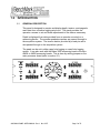
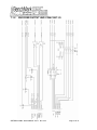
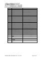
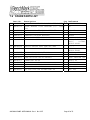
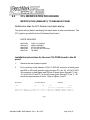
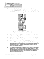
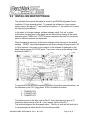
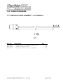
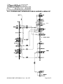
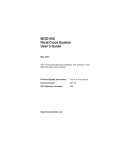
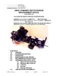
OPERATIONS AND MAINTENANCE MANUAL
WINCH OPERATORS PANEL
BAKER ATLAS 5715XA PANEL
F140529000
Kerr p/n AMS4A040
TABLE OF CONTENTS
SECTION
DESCRIPTION
1.0
GENERAL DESCRIPTION
2.0
STARTUP AND OPERATING INSTRUCTIONS
3.0
DETAILED DESCRIPTION OF FEATURES
4.0
MENU SETTINGS – AM5K MODE
5.0
MENU SETTINGS – AM3K MODE
6.0
MENU SETTINGS – FOCUS MODE
7.0
DRAWINGS, SETUP PROCEDURES AND PARTS LISTS
8.0
CCL MODIFICATION PROCEDURE
9.0
INSTALLING NEW SOFTWARE
10.0
CABLE DRAWINGS
11.0
CE TEST CERTIFICATES
AMS4A040 PANEL USER MANUAL Rev L Nov 2007
Page 1 of 51
1.0
INTRODUCTION
1.1
GENERAL DESCRIPTION
This panel is designed to acquire and display depth, tension, and magnetic
mark data from a wireline logging winch unit. The panel provides the
operator a means to set and make adjustments to the data as necessary.
Depth is displayed from data provided from an encoder mounted on a
measuring device. The encoder quadrature pulses are passed through to
the acquisition system. The tension data is provided by a load pin and is
also passed through to the acquisition system.
The panel can be set in either open hole logging or cased hole logging
modes. It can also work with the Baker 3086 measuring head or the Kerr
AM3K or AM5K measuring heads. This is done by setting jumpers on the
main processor board (refer to section 2.1).
AMS4A040 PANEL USER MANUAL Rev L Nov 2007
Page 2 of 51
1.2
FEATURES AND SPECIFICATIONS
--
Digital displays for depth, line speed, tension and magnetic marks (or CCL offset)
--
Analog incremental tension meter, 4 inch (108 mm) dia., 270 degree
--
Differential or Incremental tension zero push button switch
--
Excessive tension alarm setting allows operator to set tension alarm to a
predetermined value. Contact closure is provided for winch shutdown
--
Zero Depth button - sets depth to 0. Depressing button again resets depth to
previous setting. Only works when line speed is zero
--
Approaching surface alarm
--
Depth adjust up or down switches. Only works when winch is stopped
--
Load cell zero & calibrate controls. Only works when there is no load on cable
--
Depth & tension saved in non-volatile memory at power loss
--
Outputs for Magnetic Marks, Tension and Encoder to interface to an acquisition
system.
--
RS485 Interface for additional control and data outputs.
--
Can be set to display either English or Metric units.
AMS4A040 PANEL USER MANUAL Rev L Nov 2007
Page 3 of 51
2.0 STARTUP AND SYSTEM OPERATING INSTRUCTIONS
2.1
JUMPER SETTINGS
A row of jumpers are located on the internal processor board. These
jumpers are used to set the panel in different configurations.
The software that runs this system is stored in an EPROM located as
shown below. To update the software replace this EPROM with one
containing the latest version of software. The current version at the writing
of this document is 4001.23.
J1 on = DEPTH IN METERS
J1 off = DEPTH IN FEET
J2 on = TENSION IN KG
J2 off = TENSION IN POUNDS
J3 on = AM3K + CASE OR HOIST
J4 off = Rev D or earlier PC board
J4 on = Rev E PC board
J5 on = AM5K + FOCUS mode
J3 + J5 off = AM5K + CASE
In the event of a jumper change, software change, panel "lock up" or other
malfunction, the processor in the panel can be rebooted by turning off the
panel, depressing the T-ZERO and T-TEST buttons simultaneously then
turn the power back on while the buttons are depressed.
When the panel is rebooted, all the menu settings will be returned to the
default settings. “RESET” should be displayed on the tension display
during re-boot if 3K or 5K is selected.
AMS4A040 PANEL USER MANUAL Rev L Nov 2007
Page 4 of 51
2.2
OPERATING INSTRUCTIONS
2.1
Power up panel and verify it is working properly.
2.2
Verify the panel is configured to match the system (head type, Acquisition
System, encoder, etc.) Refer to section 2.1 for jumper settings
2.3
Set line size to match cable size installed in head (refer to menu settings).
2.4
Set Tension Alarm and the Tension Shutdown values.
2.5
Set up acquisition system:
2.6
Set depth adjust value.
2.7
Install cable in measuring head and lay it slack on the ground.
2.8
Zero the tension value by pressing T-Zero. Verify that panel tension reads
0. Verify tension is recorded on acquisition system.
2.9
Press T-Test and verify that panel tension reads 5000 (3k mode) or 10000
(5k or FOCUS mode). Verify tension is being properly recorded on
acquisition system.
2.10
Pull tool to depth 0 position. Press D-Zero and verify that panel depth
reads 0. Set acquisition system depth to 0 at this time.
AMS4A040 PANEL USER MANUAL Rev L Nov 2007
Page 5 of 51
3.0 DETAILED DESCRIPTION OF FEATURES
3.1
FRONT PANEL
3.1.1 ANALOG TENSION METER
This meter displays either differential or incremental tension. This
provides a more visual display of tension change.
3.1.2 INCREMENTAL/TOTAL TENSION SWITCH
This switch will change the analog meter from Incremental tension to
Differential tension. Incremental tension provides a high resolution
tension scale. It must be periodically reset as tension increases or
decreases to keep it from pegging out. Differential tension provides
a delta tension reading. The meter will slowly reset itself to 0 so the
reset switch is not necessary.
3.1.3 METER RESET SWITCH
This switch will reset the meter to the 0 (center) position.
3.1.4 DEPTH DISPLAY
This meter provides a digital display of depth.
3.1.5 LINE TENSION DISPLAY
This meter provides a digital display of total line tension.
3.1.6 LINE SPEED DISPLAY
This meter provides a digital display of line speed.
3.1.7 MAGNETIC MARK DISPLAY
This meter provides a digital display of the depth where the last
mark was detected. It is also used as a CCL offset display when the
panel is configured for cased hole operations (MODE 3).
3.1.8 MAGNETIC MARK RESET
Pressing the MMD reset button clears the last mark setting. The
next mark detected will be used to set the window for any
subsequent marks.
AMS4A040 PANEL USER MANUAL Rev L Nov 2007
Page 6 of 51
3.1.9 ZERO DEPTH
Pressing this button will reset the depth to 0. Depressing the button
again will reset the depth to the previous setting. The Zero Depth
button will only work when the line speed is zero (i.e. winch not
moving).
3.1.10 MENU
Pressing this button will activate the menu software. The software
feature to be set will be displayed on the DEPTH display. The
features can be toggled through by pressing the menu button until
the desired feature is displayed.
3.1.11 + / - SWITCH
This switch is used for different functions. It is used to change the
depth setting in either an up or down direction. The winch must be
stopped before the depth can be set. In menu mode (see section
3.0) the switch is used to set menu parameters.
3.1.12 RESET SWITCH AND LED
This LED is lit and an audible alarm is sounded when the depth is
less than 100' (30 m). This is a warning to the hoist operator that
they are approaching surface and should take care to get the
equipment safely out of the well. When the LED is depressed, the
alarm will stop but the LED will continue to blink. Once the depth
reading is greater than 100' (30 m), both the alarm and the LED will
turn off.
The button is also used to reset the hoist shutdown relay in the
event of a shutdown.
Note: On earlier models of this panel this switch is labeled
APPROACHING SURFACE.
3.1.13 ENGLISH / METRIC UNITS
These LEDs will indicate if the panel is in English or metric mode. If
the depth is set to English, the English LED will be lit. If the depth is
set to Metric the Metric LED will be lit. The tension can be set to
English (LBS) or Metric (KG) but it will not light the LED.
AMS4A040 PANEL USER MANUAL Rev L Nov 2007
Page 7 of 51
3.1.14 T-ZERO SWITCH
Use this switch to set the tension to 0 at the start of a logging run.
This will zero out the tension circuit. The line should be slack
through the head at this time.
3.1.15 T-TEST SWITCH
Press T-TEST and verify that the panel tension reads 10000 lbs (5K
or FOCUS) or 5000 lbs (3K). Verify tension is being properly
recorded on acquisition system.
3.2
REAR PANEL
3.2.1 12 – 24 VDC
This connector supplies dc power for the panel operation (9 VDC
min, 30 VDC max). The panel can operate on either 12 or 24 vdc
(12 vdc is U.S. truck standard voltage, 24vdc is European truck
standard voltage). Pin A is positive, pin B is negative.
3.2.2 OVER TENSION CONTACT
This connector provides a connection to the overtension circuit
relay. When an overtension condition is active, the two pins are
connected together. In normal position the two pins are open. This
feature can be used to interface to the winch unit control system to
provide automatic hoist shutdown at an overtension condition.
3.2.3 SIGNAL INPUT
Encoder, tension, and magnetic mark signals and power are passed
through this connector to/from the sensors on the measuring head.
3.2.4 SIGNAL OUTPUT
Encoder, tension, and magnetic mark signals, processed and some
unprocessed are passed through this connector to the acquisition
system.
3.2.5 RS485 SERIAL INTERFACE
This connector provides an RS485 interface from the panel to the
acquisition system. Connectors are provided for both RS485 in and
out.
AMS4A040 PANEL USER MANUAL Rev L Nov 2007
Page 8 of 51
4.0 MENU COMMANDS – AM5K MODE
This panel has internal software which allows it to be set for various
configurations. To change the settings, press the MENU button. The feature to be
set will be displayed on the DEPTH display. Press the MENU button again until
the feature you want to set is displayed.
The parameters for each feature will be displayed on the LINE TENSION display.
Press the +/- switch to cycle through all the available parameters. When the
value you want to select is displayed, press the MENU button. ACCEPT will then
be displayed. Press + for yes, - for no.
In AM5K mode the panel is configured to work with the AM5K measuring head
and the Baker Atlas CASE acquisition system.
Jumper J3 and J5 must both be removed to put the system in this mode (refer to
section 2.1).
Following is a listing of all the available settings.
4.1
TENSION ALARM
When preset tension value is reached, alarm sounds and tension display
flashes value
Procedure:
Use +/- switch to set the tension alarm setting.
Indication:
TENALM will be displayed on the DEPTH display and the
value will be displayed on the TENSION display as it is being
set.
Selection:
Each cable size will have a corresponding Tension Alarm
setting. Only the setting for the cable size selected (see
menu option 2) can be adjusted.
Default Values
7-32
9-32
5-16
3-8
7-16
15-32
SLAM
S-SLAM
1500
2400
2400
2400
2400
2400
2400
2400
AMS4A040 PANEL USER MANUAL Rev L Nov 2007
Page 9 of 51
4.2
DELTA TENSION ALARM
When the delta tension setting is reached the alarm sounds. In
incremental mode, you must periodically press meter reset or this alarm will
sound when the tension reaches the set value. In differential mode, the
meter will reset itself and the alarm will only sound on a quick change of
tension.
4.3
Procedure:
Use +/- switch to set the Delta Tension setting.
Indication:
DTALRM will be displayed on the DEPTH display and the
value being set will be displayed on the TENSION display as
it is being adjusted.
TENSION SHUTDOWN
This value is added to the DTALRM or the TENALM settings to determine
when the shutdown relay is activated.
Example:
If the TENALM is set to 4000 and the TENSDN is set to 500, the ALARM
will sound when tension reaches 4000lbs and the OT contacts will close
when tension reaches 4500lbs
If the Tension Alarm is set to 2000 and the Shutdown is set to 150 then the
winch shutdown will occur at 2150 lbs.
Procedure:
Use +/- switch to set tension shutdown setting
Indication:
TSHTDN will be displayed on the DEPTH display and the
value will be displayed on the TENSION display as it is being
set.
Selection:
Each cable size will have a corresponding Tension Alarm
setting. Only the setting for the cable size selected can be
adjusted.
Note:
The RESET or Approaching Surface button needs to be
depressed before the winch shutdown relay will de-energize.
AMS4A040 PANEL USER MANUAL Rev L Nov 2007
Page 10 of 51
4.4
DEPTH ADJUST
The depth adjustment amount selected will automatically be added to or
subtracted from the depth input.
4.5
Procedure:
Use +/- switch to set the shim setting.
Indication:
DP-ADJ will be displayed on the DEPTH display and the
value will be displayed on the TENSION display as it is being
set. The values are feet / thousand.
Default value is 0.
CABLE SIZE
Cable size selection automatically sets load pin angle setting for the
selected cable size. Wheel size is also automatically set for the selected
cable size.
Procedure:
Indication:
Use +/- switch to select cable size.
CABLE will be displayed on the DEPTH display and the
selections will be displayed on the LINE TENSION display.
Cable Size Values available
7-32
9-32
5-16
3-8
7/16
15/32
15/32 HT (deep grooved High Tension wheel)
SLAM
(.472)
SLAMHT
S-SLAM (.484)
U-SLAM (.490)
OTHER
If OTHER is selected, two additional options are available.
LCA and WHLCIR.
LCA (Load Cell Angle). This setting allows for the use of a
sheave mounted load cell. The angle of the cable exiting the
sheave should be entered. Typically for a load cell mounted
above the top sheave the LCA would be 0. For a load cell
mounted to the bottom sheave the LCA would be 90 (90
degrees). Default value is 0.
AMS4A040 PANEL USER MANUAL Rev L Nov 2007
Page 11 of 51
WHLCIR (Wheel Circumference). This value is set to the
circumference of the measuring wheel to ensure the depth is
measured correctly. Default value is 2.0 ft.
If the Baker 3086 DWMD is used, set this value to 2.5167.
4.6
DEPTH ALARM
When Alarm depth value is reached, the alarm will sound and LED will
flash. Pressing the LED will turn off alarm but the light will continue to
flash.
4.7
Procedure:
Use +/- switch to set the depth alarm value.
Indication:
DALARM will be displayed on the DEPTH display and the
value will be displayed on the TENSION display as it is being
set. Default value is 100’
CCL / MMD
When MMD is selected, the following menu options are available.
4.7.1 MMDCOR (MMD Correction)
Use +/- switch to toggle between ON or OFF
4.7.1.1 MMD CORRECTION ON
SPACNG
Use +/- switch to toggle between 100, 25 M, 50 M.
WINDOW
The MMD window determines when the next mark can be
detected. The cable must travel at least the distance of the
setting before a mark can be detected. Marks can only be
detected if they occur within this window. If the window is set
for 2', the mark must occur within +/- 2 feet of the mark
spacing (i.e. if spacing is set to 100 then the mark must occur
within 98 – 102 feet).
Procedure:
Use +/- switch to change MMD window value.
AMS4A040 PANEL USER MANUAL Rev L Nov 2007
Page 12 of 51
Indication:
MMD will be displayed on the DEPTH display
and the window value will be displayed on the
TENSION display as it is being set.
Pressing the MMD reset button clears the last mark setting.
MMD LOG
The depth of the first 25 detected marks is stored in memory
and can be displayed.
Procedure:
Use +/- switch to toggle through all of the marks
that have been detected. This starts from the
last mark detected. Pressing depth 0 will clear
all the stored marks.
Indication:
MMD DP will be displayed on the DEPTH
display and the mark depth will be displayed on
the TENSION display.
TOOLWT
The weight of the tool string at the end of the cable.
Default value is 1000 lbs.
FLUIDW
The fluid weight of the well bore fluids.
Default value is 8.3 lbs.
4.7.1.2 MMD CORRECTION OFF
SPACNG
Procedure: Use +/- switch to toggle between 100’, 25M, 50M.
WINDOW
The MMD window determines when the next mark can be
detected. The cable must travel at least the distance of the
setting before a mark can be detected. Marks can only be
detected if they occur within this window. If the window is set
for 5', the cable must travel 5' from the last mark before a new
mark can be detected.
AMS4A040 PANEL USER MANUAL Rev L Nov 2007
Page 13 of 51
MMD LOG
The depth of the first 25 detected marks is stored in memory
and can be displayed.
Procedure:
Use +/- switch to toggle through all of the marks
that have been detected. This starts from the
last mark detected. Pressing depth 0 will clear
all the stored marks.
4.7.2 CCL OFFSET
The CCL depth will be displayed on the MMD/CCL display.
This makes it easier to monitor CCL depth in addition to bottom of
tool depth.
Procedure:
Use +/- switch to set the CCL offset depth
Indication: CCL will be displayed on the DEPTH display and the
value will be displayed on the TENSION display as it is being set.
Use +/- switch to set the CCL offset.
4.7.3 CCL LOG
When CCL LOG is selected the panel will log collars.
When a casing collar signal is input, the current depth will be
displayed on the CCL display.
NOTE: The CCL gain pot located on the PCB mounted to the
inside rear of the panel may need to be adjusted to detect
collars properly.
The following menu options are available:
4.7.3.1
LOG CCL
Displays latest 100 collars. Will overwrite the oldest collar
after 100.
Press the +/- switch and you will be able to see the depth at
which each casing collar was detected. The MMD/CCL
display will display the depth of each collar when the switch is
pressed.
AMS4A040 PANEL USER MANUAL Rev L Nov 2007
Page 14 of 51
4.7.3.2
CCL DLY
Use +/- switch to set delay from 1.0 to -0.1 Adds or subtracts
to detected collar depth.
4.7.3.3
CCL_BP
Turns detected CCL audio on or off.
4.7.4 STRETCH CORRECTION
Use +/- switch to toggle between ON or OFF
When STRCOR is on, the panel will automatically correct depth to
compensate for cable stretch. Stretch in the wireline is compensated
in the following manner:
As the tool is lowered into the well the depth traveled is measured
using the optical encoders 10 times a second. The tension is used
to “back out” the stretch on the wireline for that segment and a non
stretched depth is calculated by keeping a tally of all of the
segments. This summed value is used in the following manner to
calculate the depth:
If the tension is less than the calculated line weight the tool is
assumed to be floating or supported in some other manner. The
tension is due to the line weight so the stretch added is = summed
depth * tension * Ks * 1/2 where Ks is the stretch coefficient. If the
tension is greater than the line weight the stretch due to the line
weight is calculated as above and all other weight is assumed to be
acting over the entire length of the cable or = sum depth *((line
weight * ½) + (tension-line weight)) * Ks
4.8
ENCODER
The value selected will automatically be used as the encoder input pulses
per revolution (PPR) setting.
Procedure:
Use +/- switch to set the ENCODER Pulse Per Revolution
setting.
Indication:
ENCODR will be displayed on the DEPTH display and the
value will be displayed on the TENSION display.
Default value is 512.
Note: This setting does not change the encoder out setting. The encoder
out setting is always set to 256 ppf.
AMS4A040 PANEL USER MANUAL Rev L Nov 2007
Page 15 of 51
4.9
ENCODER DIRECTION
The value selected will toggle the encoder direction between UP and
Down.
Procedure:
Use +/- switch to set the ENCODER direction setting.
Indication:
ENCDIR will be displayed on the DEPTH display and either
UP or DN value will be displayed on the TENSION display.
Default value is UP.
4.10
ENCODER SELECT
This function allows the user to change encoders by selecting
a different encoder connected to the panel.
Procedure:
Use +/- switch to select which encoder input on the rear panel
will be used.
Indication:
ENCSEL will be displayed on the DEPTH display and the
encoder selected appears on the Depth display.
a. ENC 1
b. ENC 2
Note: Encoder 1 will always turn the opposite direction from
encoder 2. In direct mode (see section 3.11), the encoder output
will be in the same direction as encoder 1.
4.11
ENCODER OUT
This setting determines which encoder pulses that will be output to the
acquisition system. Two options are available, Direct or Corrected pulses.
Direct will send out encoder pulses identical to the uncorrected pulses
coming from encoder 1. None of the corrections applied by the panel will
be sent to the acquisition system.
Correct will send out encoder pulses to the acquisition system that include
all the corrections that the panel applies such as Depth Adjust (shim),
MMD Correction, Wheel Size, etc.
Procedure:
Use +/- switch to switch between Direct (DIRECT) or
Corrected (CORRECT) pulses.
Indication:
DIRECT or CORECT will be displayed on the DEPTH display.
AMS4A040 PANEL USER MANUAL Rev L Nov 2007
Page 16 of 51
5.0 MENU COMMANDS – AM3K MODE
In this mode (cased hole) the panel is configured to work with the AM3K
measuring head and the Baker Atlas CASE and HOIST acquisition systems.
Jumper J3 must be installed to put the system in this mode (refer to section 2.3).
5.1
TENSION ALARM
When preset tension value is reached, alarm sounds and tension display
flashes value
Procedure:
Use +/- switch to set the tension alarm setting.
Indication:
TENALM will be displayed on the DEPTH display and the
value will be displayed on the TENSION display as it is being
set.
Selection:
Each cable size will have a corresponding Tension Alarm
setting. Only the setting for the cable size selected (see
menu option 2) can be adjusted.
Default Values
7-32
9-32
5-16
3-8
5.2
1500
2400
2400
2400
DELTA TENSION ALARM
When the delta tension setting is reached the alarm sounds. In
incremental mode, you must periodically press meter reset or this alarm will
sound when the tension reaches the set value. In differential mode, the
meter will reset itself and the alarm will only sound on a quick change of
tension.
Procedure:
Use +/- switch to set the Delta Tension setting.
Indication:
DTALRM will be displayed on the DEPTH display and the
value being set will be displayed on the TENSION display as
it is being adjusted.
AMS4A040 PANEL USER MANUAL Rev L Nov 2007
Page 17 of 51
5.3
TENSION SHUTDOWN
This value is added to the DTALRM or the TENALM settings to determine
when the shutdown relay is activated.
Example:
If the TENALM is set to 4000 and the TENSDN is set to 500, the ALARM
will sound when tension reaches 4000lbs and the OT contacts will close
when tension reaches 4500lbs
If the Tension Alarm is set to 2000 and the Shutdown is set to 150 then the
winch shutdown will occur at 2150 lbs.
5.4
Procedure:
Use +/- switch to set tension shutdown setting
Indication:
TSHTDN will be displayed on the DEPTH display and the
value will be displayed on the TENSION display as it is being
set.
Selection:
Each cable size will have a corresponding Tension Alarm
setting. Only the setting for the cable size selected can be
adjusted.
Note:
The RESET or Approaching Surface button needs to be
depressed before the winch shutdown relay will de-energize.
DEPTH ADJUST
The depth adjustment amount selected will automatically be added to or
subtracted from the depth input.
5.5
Procedure:
Use +/- switch to set the shim setting.
Indication:
DP-ADJ will be displayed on the DEPTH display and the
value will be displayed on the TENSION display as it is being
set. The values are feet / thousand.
Default value is 0.
LOGGING SYSTEM TYPE
This setting determines the encoder pulse rate that will be output to the
acquisition system. The tension scale will also be determined by this
setting.
AMS4A040 PANEL USER MANUAL Rev L Nov 2007
Page 18 of 51
Procedure:
Use +/- switch to select Logging System type.
Indication:
LOGSYS will be displayed on the DEPTH display. and either
CASE or HOIST will be displayed on the TENSION display.
CASE:
Encoder output:
Tension:
256 pulses per foot
1.5vdc = 20,000 lbs
HOIST:
Encoder output:
Tension:
600 pulses per foot
5vdc = 10,000 lbs
Note: Use the 4-20ma output signal for tension to the HOIST
system. Install a 250 ohm resistor across the 4-20ma output
to get the 0 – 5vdc voltage drop required.
5.6
CABLE SIZE
Cable size selection automatically sets load pin angle setting for the
selected cable size. Wheel size is also automatically set for the selected
cable size.
Procedure:
Indication:
Use +/- switch to select cable size.
CABLE will be displayed on the DEPTH display and the
selections will be displayed on the LINE TENSION display.
Cable Size Values available
7-32
9-32
5-16 (Default setting)
3-8
5.7
DEPTH ALARM
When Alarm depth value is reached, the alarm will sound and LED will
flash. Pressing the LED will turn off alarm but the light will continue to
flash.
Procedure:
Use +/- switch to set the depth alarm value.
Indication:
DALARM will be displayed on the DEPTH display and the
value will be displayed on the TENSION display as it is being
set. Default value is 100’
AMS4A040 PANEL USER MANUAL Rev L Nov 2007
Page 19 of 51
5.8
CCL
When selected, two other options will be available CCL OFFSET and CCL LOG
5.8.1 CCL OFFSET
The CCL depth will be displayed on the MMD/CCL display.
This makes it easier to monitor CCL depth in addition to bottom of
tool depth.
Procedure:
Use +/- switch to set the CCL offset depth
Indication: CCL will be displayed on the DEPTH display and the
value will be displayed on the TENSION display as it is being set.
Use +/- switch to set the CCL offset.
5.8.2 CCL LOG
When CCL LOG is selected the panel will log collars.
When a casing collar signal is input, the current depth will be
displayed on the CCL display.
NOTE: The CCL gain pot located on the PCB mounted to the
inside rear of the panel may need to be adjusted to detect
collars properly.
The following menu options are available:
LOG CCL
Displays latest 100 collars. Will overwrite the oldest collar
after 100.
Press the +/- switch and you will be able to see the depth at
which each casing collar was detected. The MMD/CCL
display will display the depth of each collar when the switch is
pressed.
CCL DLY
Use +/- switch to set delay from 1.0 to -0.1 Adds or subtracts
to detected collar depth.
CCL_BP
Turns detected CCL audio on or off.
AMS4A040 PANEL USER MANUAL Rev L Nov 2007
Page 20 of 51
5.9
STRETCH CORRECTION
Use +/- switch to toggle between ON or OFF
When STRCOR is on, the panel will automatically correct depth to
compensate for cable stretch. The following information will then be
requested:
Stretch in the wireline is compensated in the following
manner:
As the tool is lowered into the well the depth traveled is measured
using the optical encoders 10 times a second. The tension is used
to “back out” the stretch on the wireline for that segment and a non
stretched depth is calculated by keeping a tally of all of the
segments. This summed value is used in the following manner to
calculate the depth:
If the tension is less than the calculated line weight the tool is
assumed to be floating or supported in some other manner. The
tension is due to the line weight so the stretch added is = summed
depth * tension * Ks * 1/2 where Ks is the stretch coefficient. If the
tension is greater than the line weight the stretch due to the line
weight is calculated as above and all other weight is assumed to be
acting over the entire length of the cable or = sum depth *((line
weight * ½) + (tension-line weight)) * Ks
5.10
ENCODER
The value selected will automatically be used as the encoder input pulses
per revolution (PPR) setting.
Procedure:
Use +/- switch to set the ENCODER Pulse Per Revolution
setting.
Indication:
ENCODR will be displayed on the DEPTH display and the
value will be displayed on the TENSION display.
Default value is 1200.
5.11
ENCODER DIRECTION
The value selected will toggle the encoder direction between UP and
Down.
Procedure:
Use +/- switch to set the ENCODER direction setting.
AMS4A040 PANEL USER MANUAL Rev L Nov 2007
Page 21 of 51
Indication:
ENCDIR will be displayed on the DEPTH display and either
UP or DN value will be displayed on the TENSION display.
Default value is UP.
5.12
ENCODER OUT
This setting determines which encoder pulses that will be output to the
acquisition system. Two options are available, Direct or Corrected pulses.
Direct will send out encoder pulses identical to the uncorrected pulses
coming from encoder 1. None of the corrections applied by the panel will
be sent to the acquisition system.
Correct will send out encoder pulses to the acquisition system that include
all the corrections that the panel applies such as Depth Adjust (shim),
MMD Correction, Wheel Size, etc.
Procedure:
Use +/- switch to switch between Direct (DIRECT) or
Corrected (CORRECT) pulses.
Note:
The encoder output is fixed regardless of this setting or the
encoder PPR setting.
CASE = 256 pulses per foot
HOIST = 600 pulses per foot
AMS4A040 PANEL USER MANUAL Rev L Nov 2007
Page 22 of 51
6.0 MENU COMMANDS – FOCUS MODE
In this mode (open hole) the panel is configured to work with the AM5K measuring
head and the Baker Atlas FOCUS acquisition system.
In this mode, the panel becomes a slave to the FOCUS system. Any changes to
settings made in the panel will only change the panel displays and will not be
output to the computer system. The FOCUS system updates the panel by means
of the RS485 serial ports on the rear of the panel.
Jumper J3 must be removed and J5 installed to put the system in this mode (refer
to section 2.1).
6.1
CABLE SIZE
Cable size selection automatically sets load pin angle setting for the
selected cable size.
If other is selected, the LCA value needs to be entered. This value is
based on the bend angle of the cable over the tension wheel. This value is
empirically derived and must be furnished by the measuring head
manufacturer.
Procedure:
Use +/- switch to select cable size.
Indication:
CABLE will be displayed on the DEPTH display and the
selections will be displayed on the LINE TENSION display.
Cable Size Values available
7-32
9-32
5-16
3-8
7-16
15-32
SLAM
S-SLAM
Default value is 7-16
AMS4A040 PANEL USER MANUAL Rev L Nov 2007
Page 23 of 51
6.2
TEN ALARM
When preset tension value is reached, alarm sounds and tension display
flashes value
Procedure:
Use +/- switch to set the tension alarm setting.
Indication:
TALARM will be displayed on the DEPTH display and the
value will be displayed on the TENSION display as it is being
set.
Selection:
Each cable size will have a corresponding Tension Alarm
setting. Only the setting for the cable size selected (see
menu option 1) can be adjusted.
Default Values
7-32
9-32
5-16
3-8
7-16
15-32
SLAM
S-SLAM
6.3
1500
2400
2400
2400
2400
2400
2400
2400
TENSION SHUTDOWN
When value is reached, alarm sounds, tension display flashes value, and
tension contact closure switch is closed. This can be used to provide a
signal to automatically stop the winch.
Procedure:
Use +/- switch to set tension shutdown setting
Indication:
TSHTDN will be displayed on the DEPTH display and the
value will be displayed on the TENSION display as it is being
set.
Selection:
Each cable size will have a corresponding Tension Alarm
setting. Only the setting for the cable size selected can be
adjusted.
Default Values
7-32
2000
9-32
3000
AMS4A040 PANEL USER MANUAL Rev L Nov 2007
Page 24 of 51
5-16
3-8
7-16
15-32
SLAM
S-SLAM
Note:
6.4
3500
3500
3500
3500
3500
3500
The RESET or Approaching Surface button needs to be
depressed before the winch shutdown relay will de-energize.
DELTA TENSION ALARM
When the delta tension setting is reached the alarm sounds. In
incremental mode, you must periodically press meter reset or this alarm will
sound when the tension reaches the set value. In differential mode, the
meter will reset itself and the alarm will only sound on a quick change of
tension.
6.5
Procedure:
Use +/- switch to set the Delta Tension setting.
Indication:
DTALRM will be displayed on the DEPTH display and the
value being set will be displayed on the TENSION display as
it is being adjusted.
DELTA TENSION SHUTDOWN
When value is reached, alarm sounds, tension display flashes value, and
tension contact closure switch is closed. This can be used to provide a
signal to automatically stop the winch.
Procedure:
Use +/- switch to set tension shutdown setting
Indication:
DTSTDN will be displayed on the DEPTH display and the
value will be displayed on the TENSION display as it is being
set.
Note:
This parameter is derived from the reading on the analog
meter. If the DTSHDN value is set to 500 then whenever the
tension reading on the meter is greater than 500 the winch
shutdown relay will be activated.
Note:
The RESET or Approaching Surface button needs to be
depressed before the winch shutdown relay will de-energize.
AMS4A040 PANEL USER MANUAL Rev L Nov 2007
Page 25 of 51
6.6
DEPTH ADJUST
The amount selected will automatically be added or subtracted from the
depth input.
Procedure:
Use +/- switch to set the shim setting.
Indication:
DP-ADJ will be displayed on the DEPTH display and the
value will be displayed on the TENSION display as it is being
set. The values are feet / hundred.
Default value is 0.
6.7
DEPTH ALARM
When Alarm depth value is reached, the alarm will sound and LED will
flash. Pressing the LED will turn off alarm but the light will continue to
flash.
6.8
Procedure:
Use +/- switch to set the depth alarm value.
Indication:
DALARM will be displayed on the DEPTH display and the
value will be displayed on the TENSION display as it is being
set.
Default value is 100’
MMD
The MMD window determines when the next mark can be detected. The
cable must travel at least the distance of the value set before a mark can
be detected. Marks can only be detected if they occur within this window.
I.E. If the window is set for 95', the cable must travel 95' from the last mark
before a new mark can be detected.
Procedure:
Use +/- switch to change MMD window value.
Indication:
MMD will be displayed on the DEPTH display and the window
value will be displayed on the TENSION display as it is being
set.
Pressing the MMD reset button clears the last mark setting.
Default value is 5’
AMS4A040 PANEL USER MANUAL Rev L Nov 2007
Page 26 of 51
6.9
ENCODER
The value selected will automatically be used as the encoder input pulses
per revolution (PPR) setting.
6.10
Procedure:
Use +/- switch to set the ENCODER Pulse Per Revolution
setting.
Indication:
ENCODR will be displayed on the DEPTH display and the
value will be displayed on the TENSION display.
Selection:
1200 (600 ppf or 1968 ppm)
780 (390 ppf or 1280 ppm) – Default Value
512 (256 ppf or 1680 ppm)
ENCODER DIRECTION
The value selected will toggle the encoder direction between UP and
Down.
6.11
Procedure:
Use +/- switch to set the ENCODER direction setting.
Indication:
ENCDIR will be displayed on the DEPTH display and either
UP or DN value will be displayed on the TENSION display.
Default value is UP.
ENG – MET UNITS
The depth and tension values will be displayed in the units selected.
Procedure:
Use +/- switch to set the MEASUREMENT UNITS setting.
Indication:
UNITS will be displayed on the DEPTH display. The
selection can be toggled through any combination of English
or Metric units. The selection will be displayed on the
TENSION display. The ENGLISH (green) LED display will be
lit when FT – LBS is selected and the METRIC (red) LED will
be lit when in any of the other modes.
Selection:
FT - LBS
FT - KG
MT - LBS
MT - KG
Default value is FT – KG
AMS4A040 PANEL USER MANUAL Rev L Nov 2007
Page 27 of 51
6.12
HEAD TYPE
Two options are available: 5 (AM5K) and OTHER
If OTHER is selected, two additional options are available.
LCA and WHLCIR.
LCA (Load Cell Angle). This setting allows for the use of a
sheave mounted load cell. The angle of the cable exiting the
sheave should be entered. Typically for a load cell mounted
above the top sheave the LCA would be 0. For a load cell
mounted to the bottom sheave the LCA would be 90 (90
degrees). Default value is 0.
WHLCIR (Wheel Circumference). This value is set to the
circumference of the measuring wheel to ensure the depth is
measured correctly. Default value is 2.0 ft. To use a Baker
3086 measuring head set the wheel size to 2.517 ft.
6.13
DELTA TENSION SCALE
This option allows the Delta Tension scale to be set to either 500 or 1000
lbs or kgs. The meter has two scales, the outer scale is 500 and the inner
scale is 1000.
Procedure:
Use +/- switch to set the Delta Tension Scale setting.
Indication:
DTSCLE will be displayed on the DEPTH display and either
500 or 1000 will be displayed on the TENSION display.
Default value is 1000.
AMS4A040 PANEL USER MANUAL Rev L Nov 2007
Page 28 of 51
7.0 DRAWINGS AND PARTS LISTS
7.1 Main Processor Board
AMS4A040 PANEL USER MANUAL Rev L Nov 2007
Page 29 of 51
7.1.1
ENCODER AND MMD INPUTS
AMS4A040 PANEL USER MANUAL Rev L Nov 2007
Page 30 of 51
7.1.2
ENCODER OUTPUT AND COM PORT I/O
AMS4A040 PANEL USER MANUAL Rev L Nov 2007
Page 31 of 51
7.1.3 LOAD PIN AND TENSION I/O
AMS4A040 PANEL USER MANUAL Rev L Nov 2007
Page 32 of 51
7.1.4 JUMPERS – BUTTONS
AMS4A040 PANEL USER MANUAL Rev L Nov 2007
Page 33 of 51
7.1.5 POWER SUPPLIES
AMS4A040 PANEL USER MANUAL Rev L Nov 2007
Page 34 of 51
7.2 Wire List
AMS 4A040 WIRING LIST-P2 - Screw Terminal Block
REV L
P2 -1
BATT +
RED
P2 -2
BATT CONTACT
CLOSURE N.O.
CONTACT
CLOSURE N.C.
CONTACT
CLOSURE COM
BLK - B
P1-7
(FUSE
BRD)
J1 B
GRN - B
J6 A
-----
-----
BRN - A
J6 B
P2 -3
P2 -4
P2 -5
SWITCHED POWER
Tension Contact Closure Back
Panel
Tension Contact Closure Back
Panel
P4 - USER SWITCHES (12 PIN)
P4 - 2
P4 - 6
P4 - 7
P4 - 8
P4 - 9
P4 - 10
P4-11
P4-12
DCM
BLK
ZERO DIFF.
TENSION
TEN TEST
ZERO CAL
CANCEL DEPTH
ALARM
ZERO DEPTH
DEPTH ADJ
DOWN
DEPTH ADJ UP
P5 - SPARE (12 PIN)
P5 - 1
+5V
P5 - 2
MENU
P5 - 3
DIFF / INC
P5 - 6
MMD RESET
One side of SW2, SW3, SW4,
SW5, SW6, SW7, SW8, SW9,
ENGLISH-, SW 10
BLK
GRY
BRN
BLU
VIO
BLU
ORA
RED
YEL
GRN
VIO
P6 - ANALOG IN/OUT (16 PIN)
LOAD PIN POWER
P6 - 1
RED
+
LOAD PIN POWER
P6 - 2
BLK
P6 - 3
LOAD PIN SIG+
ORA
AMS4A040 PANEL USER MANUAL Rev L Nov 2007
SW4 N.O.
SW5 N.O.
SW6 N.O.
SW10
N.O
SW9 N.O.
SW7 N.O.
Dn Contact of SW7
DN
SW7 N.O.
Up Contact of SW7
UP
D1 4
SW8
SW 3
SW 2
P1-10
FUS BRD
P1-9 FUS
BRD
J2 10
DISPLAY POWER
MENU SELECT
LOAD PIN +15V
LOAD PIN -15V
LOAD PIN SIG+
Page 35 of 51
P6 - 4
P6 - 7
P6 - 8
P6 - 9
P6 - 10
P6 - 11
P6 - 15
P6 - 16
LOAD PIN SIGSHUNT CAL
ENABLE
ACM
4to20OUT
ACM
0-2V OUT
(TENSION)
DIFF TENSION
METER DIFF TENSION
METER +
BLK
J2 22
LOAD PIN SIG-
GRN
J2 9
SHUNT CAL
BLK
BRN
BLK
J2 21
J5-12
J5-21
GROUND
4 to 20 mA to system
TENSION OUT- TO SYSTEM
GRAY
J5-9
TENSION OUT+ TO SYSTEM
YEL
M1 -
BLU
M1 +
P7 - COMMUNICATIONS (12 PIN)
P7 - 1
RS485 TX+
GRAY
P7-2
RS485 TX-
BLK
P7 - 3
RS485RX-
GRN
P7 - 4
RS485RX+
BLU
P7 - 7
COM2 TXD
ORG
P7 - 9
GND
BLK
P7 - 12
GND
BLK
J3-8 + J48
J3-9 + J49
J3-5 + J45
J3-4 + J44
D1-5, D25, D3-5,
D4-5
J3-3 + J43
D1 1
P8 - QUADRATURE OUT / INDICATORS (16 PIN)
P8 - 1
METRIC LED BRN
METRIC LED+ &
METRIC
P8 - 2
ORN
6.8VZKathode
LED+ &
6.8VZKat
hode
EXCESSIVE
P8 - 3
GRAY
DS 1+
TENSION LED
EXCESSIVE
P8 - 4
WHITE
DS 1TENSION LED
EXCESSIVE
GRN
P8 - 5
ALM1 TENSION ALM Beeper
EXCESSIVE
P8 - 6
YEL
ALM1 +
TENSION ALM +
AMS4A040 PANEL USER MANUAL Rev L Nov 2007
RS485 TX+ (2 WIRES)
RS485 TX- (2 WIRES)
RS485 RX- (2 WIRES)
RS485 RX+ (2 WIRES)
DISPLAY DATA - FOUR
WIRES CONNECTED
TOGETHER
RS485 GND (2 WIRES)
DISPLAY GND
METRIC LED KATHODE (-)
METRIC LED ANODE &
6.8VZKathode 6.8VZAnode to
ENGLISH LED +
LED
LED
Beeper
Beeper
Page 36 of 51
P8 - 9
P8 - 10
P8 - 11
P8 - 12
P8 - 13
P8 - 16
APPROACHING
SURFACE LED APPROACHING
SURFACE LED +
PHASE 1B*
PHASE 1B
PHASE 1A*
PHASE 1A
P9 - ENCODER 1 (12 PIN)
P9 - 1
DCM
P9 - 2
DCM
VIO
SW 10
+1 (inline with silver plate)
BLU
SW 10
-1 (opposite silver plate)
YEL
BLU
RED
ORA
J5 15
J5 3
J5 14
J5-2
Quadrature Out - PHASE B*
Quadrature Out - PHASE B
Quadrature Out - PHASE A*
Quadrature Out - PHASE A
BLK
BLK
J2 14
J5-13
NO
CONNEC
T
J2 4
J2 16
J2 3
J2 15
Encoder Ground
Encoder Ground
J2 17
NO
CONNEC
T
J2 7
J2 19
J2 6
J2 18
Encoder Ground
P9 - 5
ENCODER PWR TO FUSE
YEL
P9 - 8
P9 - 9
P9 - 11
P9 - 12
ENCODER 1B
ENCODER 1B *
ENCODER 1A
ENCODER 1A*
BLU
GRN
ORA
RED
P10 - ENCODER 2 (12 PIN)
P10 - 1
DCM
BLK
P10 - 5
ENCODER PWR TO FUSE
YEL
P10 - 8
P10 - 9
P10 - 11
P10 - 12
ENCODER 2B
ENCODER 2B *
ENCODER 2A
ENCODER 2A*
BLU
GRN
ORA
RED
P11 +/- 15 VDC (12 PIN)
P11-1
DIG GND
5V ENCODER
PWR - TO FUSE
P11-3
BOARD
BLK
YEL
P11 - 8
WEAK MARK+
WHT
P11 - 9
WEAK MARK-
VIO
P11-10
MMD POWER +
RED
P11-11
P11-12
STRONG MARK +
STRONG MARK -
BLU
GRAY
AMS4A040 PANEL USER MANUAL Rev L Nov 2007
J2-23
P1-2, P16 fuse
board
J2 24, J522
J2 12, J510
P1-3 FUS
BRD
J2-25
J2-13
Encoder input
Encoder input
Encoder input
Encoder input
FUSE BOARD P1:6
Encoder input
Encoder input
Encoder input
Encoder input
MMD POWER COMMON
FUSE BOARD P1-2 and P1-6
(2 wires)
WEAK MARK IN- (2 WIRES)
WEAK MARK IN + (2 WIRES)
MMD POWER +
STRONG MARK IN STRONG MARK IN +
Page 37 of 51
D1 DISPLAY - MMD DEPTH (10 PIN)
D1-2
GND
BLK
D1-6
+5V OUT
RED
D2 1
D2 4
GND OUT
POWER OUT
D2 DISPLAY - DEPTH (10 PIN)
D2-2
GND
BLK
D2-6
+5V OUT
RED
D3 1
D3 4
GND OUT
POWER OUT
D3 DISPLAY - LINE TENSION (10 PIN)
D3-2
GND
BLK
D3-6
+5V OUT
RED
D4 1
D3 4
GND OUT
POWER OUT
D4 DISPLAY - LINE SPEED
FUSE BOARD
SW1 ON/OFF 12V
P1-1
BATT
ENCODER1 PWR
P1-4
FUSED
MMD PWR (+15)
P1-5
FUSED
ENCODER2 PWR
P1-8
FUSED
P1-11
LOAD PIN -15
P1-12
LOAD PIN +15
J3 RS485
J3-1
J3-2
J3-6
J3-7
RED
SW1COM
J2-2
RED
J2-11
J2-5
J2-20
J2-8
IN DB9-P (DB9-MALE)
CTS+
ORN
CTSBRN
RTS+
VIO
RTSGRY
J4-1
J4-2
J4-6
J4-7
J4 RS485 OUT DB9-S (DB9-FEMALE)
J2 EXTERNAL SIGNALS IN
J5 OUTPUT TO SYSTEM
J1 12V POWER IN
J1-A
12V POWER IN
RED
AMS4A040 PANEL USER MANUAL Rev L Nov 2007
SW1 NO
12V POWER TO PANEL
Page 38 of 51
7.3 FUSE BOARD AND POWER WIRING
Refer to 5.2 for wirelist
AMS4A040 PANEL USER MANUAL Rev L Nov 2007
Page 39 of 51
7.4
DIGITAL DISPLAY SETUP
The four digital displays can be set for address, baud rate, and brightness.
The button nearest the connector selects the parameter (address, baud rate,
brightness).
The center button increments the parameter up
The end button increments the parameter down.
After the parameter is set, press the parameter button again to store it.
The addresses should be set as follows:
Line Tension = 1
Line Speed = 2
Depth = 3
MMD = 4
Set Baud Rate to 9600
Set Brightness to 15
7.5 BACK PANEL CONNECTOR PINOUT
J1 A
J1 B
12 - 24 VDC IN
12 - 24 VDC GROUND
J2-2
J2 3
J2-5
J2 4
J2 6
J2 7
J2-8
J2-9
J2-10
J2-11
J2 12
J2-13
J2 14
J2 15
J2 16
J2 17
J2 18
J2 19
J2-20
J2-21
J2-22
J2-23
J2 24
ENCODER1 PWR FUSED
ENCODER 1A
ENCODER2 PWR FUSED
ENCODER 1B
ENCODER 2A
ENCODER 2B
LOAD PIN +15
SHUNT CAL
LOAD PIN SIGNAL +
MMD PWR (+15) FUSED
MARK- IN
STRONG MARK ENCODER GROUND (DCM)
ENCODER 1A*
ENCODER 1B *
ENCODER GROUND (DCM)
ENCODER 2A*
ENCODER 2B *
LOAD PIN -15
LOAD PIN GROUND (ACM)
LOAD PIN SIGNAL MMD POWER GROUND (DCM)
MARK+ IN
AMS4A040 PANEL USER MANUAL Rev L Nov 2007
ENCODER1 PWR FUSED
ENCODER INPUT
ENCODER2 PWR FUSED
ENCODER INPUT
ENCODER INPUT
ENCODER INPUT
LOAD PIN +15
MMD PWR (+15) FUSED
WEAK MARK IN + (2 WIRES)
STRONG MARK IN +
ENCODER GROUND
ENCODER INPUT
ENCODER INPUT
ENCODER GROUND
ENCODER INPUT
ENCODER INPUT
LOAD PIN -15
MMD POWER COMMON
WEAK MARK IN- (2 WIRES)
Page 40 of 51
J2-25
STRONG MARK +
J3-1
J3-2
J3-4
J3-5
J3-6
J3-7
J3-8
J3-9
CTS+ IN
CTS- IN
RS485RX+
RS485RXRTS+ IN
RTS- IN
RS485 TX+
RS485 TX-
J4-1
J4-2
J4-3
J4-4
J4-5
J4-6
J4-7
J4-8
J4-9
CTS+ OUT
CTS- OUT
GND
RS485RX+
RS485RXRTS+ OUT
RTS- OUT
RS485 TX+
RS485 TX-
J5-2
J5 3
J5-8
J5-9
J5-10
J5-13
J5 14
J5 15
J5-21
PHASE 1A
PHASE 1B
4 to 20 MA OUT
0-2V OUT (TENSION)
MARK- OUT
ENCODER GROUND (DCM)
PHASE 1A*
PHASE 1B*
TENSION
OUT
COMMON
(ACM)
MARK+ OUT
J5-22
J6 A
J6 B
STRONG MARK IN -
RS485 RX+ (2 WIRES)
RS485 RX- (2 WIRES)
RS485 TX+ (2 WIRES)
RS485 TX- (2 WIRES)
RS485 GND (2 WIRES)
RS485 RX+ (2 WIRES)
RS485 RX- (2 WIRES)
RS485 TX+ (2 WIRES)
RS485 TX- (2 WIRES)
QUADRATURE OUT - PHASE A
QUADRATURE OUT - PHASE B
4 TO 20 MA TO SYSTEM
TENSION OUT+ TO SYSTEM
WEAK MARK IN + (2 WIRES)
ENCODER GROUND
QUADRATURE OUT - PHASE A*
QUADRATURE OUT - PHASE B*
TENSION OUT- TO SYSTEM
WEAK MARK IN- (2 WIRES)
TENSION CONTACT RELAY
COMMON
TENSION CONTACT RELAY
N.O.
AMS4A040 PANEL USER MANUAL Rev L Nov 2007
Page 41 of 51
7.6 SPARE PARTS LIST
Part No.
Description
1
2
Qty Reference
AMS4P134E PC BOARD AMS40 REV E W/2xRS232 1x485
AMS4P110 METER ANALOG DIFF TENSION (+/- 1000
LBS)
4 AMS4P120 DISPLAY LED .5" SERIAL 2"X3.5"
6 ACMU1P06 LED RED DIALIGHT 5V
7 ACMU1P11 SONALERT #SC628D MALLORY
9 AMS4P020 SWITCH MTL-106D ALCO LOCKING
10 AMS4P018 SWITCH MPA-106F ALCO PUSH MOM
1
1
MOTHER BOARD
M1
4
1
1
2
5
11 AMS4P044
12 AMS4P021
SWITCH TOGGLE DPDT MOM OFF MOM
SWITCH CAPS ALCO C-22 BLACK
1
3
13 AMS7P017
28 ACMU3P01
29 ACMU3P02
SWITCH CAP ALCO C-22 RED
CONN MS3102E-14S-9P RECEPT
CONN MS3102E-14S-9S RECEPT
1
1
1
D2, D3
APPROACHING SURF
ALARM
POWER ON/OFF
MENU, T-ZERO, TTEST,
D-ZERO,
METER RESET
+ / T-ZERO, D-ZERO,
METER RESET
D-ZERO, MENU
POWER IN
OVER TENSION OUT
30
30
40
41
42
CONNECTOR DE-9P
CONNECTOR DE-9S
SWITCH PUSHBUTTON LIGHTED SPST
LENS RED C&K SWITCH
LED RED FOR C&K PUSHBUTTON SW
1
1
1
1
1
RS485 IN
RS485 OUT
APPROACHING SURF
RED LENS
RED LED
AMS4P163
AMS4P164
AMS4P041
AMS4P042
AMS4P043
AMS4A040 PANEL USER MANUAL Rev L Nov 2007
Page 42 of 51
8.0
CCL MODIFICATION PROCEDURE
MODIFICATION (AMS4A813) TO AMS4A040 PANEL
Modification adds the CCL Detector and depth display
The panel will now detect and display the depth where a collar was detected. The
CCL signal is provided from the Perforating Panel output.
PARTS REQUIRED
AMS4A686
AMS4A812
AMS4P693
AMS4P862
AMS4P787
FUSE / CCL BOARD
CABLE ASSEMBLY
AT27C512R EPROM
AT17LV256-10PU EEPROM
TIE WRAP
Installation instructions for the new CCL/FUSE board in the 40
panel.
1.
Remove the rear connector panel.
2.
Do a continuity check between J2 Pin 13 (SIG IN) connector on back panel
and R39 on 40 board (goes through connector P11 pin 12), J2 Pin 25 (SIG
IN) connector on back panel and R38 on 40 board (goes through P11 pin
11) and J2 Pin 23 and TP1 on the 40 board (goes through P11 pin 1). All
should be approximately 0 ohms. Refer to figures 1 and 2.
Rear Panel
J2
CCL/Fuse Board
P2
40 Board
U1
P2
P11
Pin 3------Black------Pin 1
Pin 13----Gray-------Pin 1-----<>-----Pin 4---Green--Gray---Pin 12
Pin 25----Blue—Gray--Pin 2-----<>-----Pin 5---Brown--Blue---Pin 11
Fig. 1
AMS4A040 PANEL USER MANUAL Rev L Nov 2007
Page 43 of 51
Fig. 2
3.
Remove connector P1 from fuse board, noting orientation of wires in plug
in relationship to the large fuse (F5). Refer to figure 3.
4.
Remove old fuse board. Refer to figure 3.
Fig. 3 – old fuse board (P1 connector orientation)
AMS4A040 PANEL USER MANUAL Rev L Nov 2007
Page 44 of 51
5.
Install new fuse board, ensuring orientation of wires in P1 are the same
orientation to large fuse (F5) as original installation. Install new cable
assembly (AMS4A812) to location P2 on the fuse board noting the location
of pin 1 on the board as shown in figure 4 as well as on the connector itself.
Fig. 4 New fuse board (R3 location, CCW arrow)
6.
Cut the wire coming from J2-23 at a convenient distance from J2 so that
another wire can be spliced to it.
7.
Cut the wire coming from J2 pin 13 at a convenient distance from J2 (SIG
IN) so that another wire can be spliced to it.
8.
Cut the wire in the new cable assembly (AMS4A812) going to the new
connector P2 Pin 1 designated by the arrow on the connector to the length
needed and splice to the wires that were cut coming from the rear panel J2
(SIG IN) pins 23 and 13. Solder the wires together and install with heat
shrink over the solder connection.
9.
Cut the wire coming from the rear panel J2 (SIG IN) pin 25 at a convenient
distance from J2 (SIG IN) so that another wire can be spliced to it. Splice
the gray wire that is inserted into the new cable assembly (AMS4A812) P2
pin 2 that will plug into the new CCL fuse board to the wire that was cut
going to J2 pin 25 on the rear panel.
AMS4A040 PANEL USER MANUAL Rev L Nov 2007
Page 45 of 51
10.
Cut to the length needed and splice the black 22 awg wire that is
connected to the new cable assembly P2 pin 3 that will plug into the new
CCL fuse board to the wire that was cut going to P11-1 on the 40 PC
board.
11.
Cut to the length needed and splice the gray 22 awg wire connected to the
new cable assembly P2 pin 4 that will plug into the new CCL fuse board to
the wire that was cut going to P11-12 on the 40 PC board.
12.
Cut to the length needed and splice the blue 22 awg wire connected to the
new cable assembly P2 pin 5 that will plug into the new CCL fuse board to
the wire that was cut going to P11-11 on the 40 PC board.
13.
Remove the old EPROM (U2) from the 40 PC board and insert the new
one provided.
14.
Remove U17 and insert the new one provided.
15.
To test the operation of the panel, adjust R3 on the CCL/Fuse board to
receive satisfactory collars if needed. The boards were set to a threshold
value of approximately +1.5V input to the CCL circuit during testing.
Setting the input to +1.5V would be a good starting point to set up the
circuit before installing the panel in a unit. CCW adjustments of R3 will
raise the threshold voltage required to acquire a CCL mark (less sensitive).
Example: If CCL marks are constant as the tools go down hole, adjust R3
CCW until CCL marks are on depth. Example #2: If no CCL marks are
found, turn R3 clockwise. An oscilloscope across CCL/Fuse board P2 pin
2 (signal) and 40 board TP1 (ground) will allow you to see the input signal
as you make your adjustments. Refer to Figures 2 and 4.
16.
Use ty-wraps to hold wires together as needed.
AMS4A040 PANEL USER MANUAL Rev L Nov 2007
Page 46 of 51
9.0 INSTALLING NEW SOFTWARE
The software that controls this panel is stored in an EPROM Integrated Circuit
located at U2 (see drawing below). To upgrade the software to a new version,
simply remove the eprom I.C. and install a new eprom I.C. (be careful not to bend
the legs during installation).
In the event of a jumper change, software change, panel "lock up" or other
malfunction, the processor in the panel can be rebooted by turning off the panel,
depressing the T-ZERO and T-TEST buttons simultaneously then turn the power
back on while the buttons are depressed.
When the panel is rebooted, all the menu settings will be returned to the default
settings. “RESET” should be displayed on the tension display during re-boot if 3K
or 5K is selected. On power up the revision of the software is displayed on the
depth display except for FOCUS mode. The current version at the writing of this
document is 4001.21.
To operate from the EPROM instead of the Micro-Controllers internal memory, set
the switches on the CPU “piggy-back” PCB (if installed) as follows:
1 - TOWARD CPU
2 – TOWARD CPU
3 - TOWARD CPU
The latest version of the Xlinx code is Rev B. Verify that the small plug in IC
located as shown above is Rev B. If not, replace it with a Rev B I.C.
This code will improve the line speed output. The Rev A code will still work but it
is recommended to install the Rev B code when possible.
AMS4A040 PANEL USER MANUAL Rev L Nov 2007
Page 47 of 51
10.0 CABLE DIAGRAMS
10.1 AMS7A022 CABLE ASSEMBLY – DC POWER IN
A=+
B=-
Kerr p/n
AMS7P061
AMS7P044
AMS7P063
Description
CABLE 16-2 SJ CORD BELDEN 8472
CONN MS3106E-14S-9S
BUSHING #9779-513-6 AMPHENOL
AMS4A040 PANEL USER MANUAL Rev L Nov 2007
Qty
5
1
1
FT
EA
EA
Page 48 of 51
10.2 LOGGING UNIT INTERFACE CABLE HARNESS AMS4A187
AMS4A040 PANEL USER MANUAL Rev L Nov 2007
Page 49 of 51
11.0
CE TEST CERTIFICATE
AMS4A040 PANEL USER MANUAL Rev L Nov 2007
Page 50 of 51
AMS4A040 PANEL USER MANUAL Rev L Nov 2007
Page 51 of 51