1
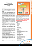
TECHNICAL DATA SHEET INTEGRATED PROTECTION RELAY IPM Version 2 Applications The IPM Integrated Protection Relay provides all the necessary protection functions to control the various types of mining machinery. The default Status Screen allows unskilled personnel to determine what is required to apply power to the machine. (See IPM User Manual 121549 for full details). Alarms Alarms can be programmed to warn of a pending trip condition. Earth Leakage The earth leakage protection function uses a 1000:1 core balance toroid to measure the earth fault current. A Residual Current Device (RCD) operating characteristic is provided with adjustable trip sensitivity and time delay. When the earth leakage reaches 100% of the selected trip level, a trip occurs. The higher the fault current measured, the faster the trip time and vice versa. (See IPM User manual 121549 for full details). Earth Continuity The earth continuity function tests for the continuity of the earthing between the outlet and the machine, via the pilot core in the trailing cable. The pilot core is also used to transfer data when a Remote Termination Module is used to achieve Machine Data Transfer. Short Circuit The short circuit function has a definite time characteristic. If the current exceeds the selected level for the pre-set time then a trip occurs. The short circuit function trips the CBR relay, which in turn can trip the main circuit breaker. Main Contactor Fail The Main Contactor Fail (MCF) protection operates if the Main Contactor (MC) fails to function by either: 1. Failing to open when required. 2. Failing to maintain insulation across the contacts when the contactor is open. Residual Current The three phase current signals are summed electronically in the IPM Relay to produce a residual current signal that can be used to detect earth fault currents. (See User Manual 121549 for full details). Remote Start This functionality is similar to that of the IPB/C/D. The remote start can be set in two modes. In one mode it is always active and in the other mode it is active only when the auxiliary digital input is closed. Overload Protection Optional CT’s can extend the relays current range. 1:100 1: 1000 0.5A – 64A 5.125A – 640A Version No: 7 Status: Approved 30/07/2014 Doc No: / Name: IPM2B001 IPM TECHNICAL DATASHEET Author / SME Approval by Tech Doc Officer 2.2.7 Process Owner Prepared by: Process Owner: Refer to Ampcontrol Intranet for latest version Page 1 of 3 IPM2B001 IPM TECHNICAL DATASHEET Version: 7, Date 30/07/2014 Features Automatic and Manual High Voltage Diode or Remote Termination Module Insulation Test operation Machine Recognition 50 Event Log with real time clock RS485 communication port interfaces to Relay & Digital Input Status to aid fault SCADA system via Modbus protocol finding 4-20mA Analogue output Local or remote operation Thermal modelling Plug-in for quick change out User friendly. Relay and Remote Burp Function for controlled fan starting Termination Module are programmed from Snore Function for controlling pumps the IPM Display Remote Start Capability Microprocessor based Status messages to indicate what is required to energise the outlet Product description The Ampcontrol IPM Integrated Protection Relay (Version IPM V2.0) is an intelligent protection relay based on microprocessor technology. All of the tripping logic and outlet control is performed by the microprocessor, so that virtually no external control is required. The IPM Integrated Relay provides the necessary functions required for protecting electrical outlets supplying underground mining machinery, powered by reeling or trailing cables, in the metalliferous industry. The relay can also be used to provide optimum overload protection of motors used on conveyors, pumps, fans and compressors. All of the protection functions are combined into a compact, plug-in unit, which can be easily changed out to minimise down time in the event of a problem with the relay. The IPM Integrated Protection Relay can provide Machine Data Transfer through the use of a Remote Termination Module (RTM) connected between the pilot and earth at the machine end of the trailing cable. Through the use of the RTM the relay parameters are automatically up loaded from a remote machine when a cable is inserted into a power outlet. The IPM’s remote start capability can also be access by use of the Ampcontrol’s Remote Termination Module. A RS485 Modbus communication port is available that can be connected to Motor Starter PLC's or a central monitoring system for continuous monitoring and fault-finding. The IPM Relay provides an isolated 4-20mA analogue output to continuously monitor Average Current, Overload, Earth Leakage and the Insulation level of the relay. An automatic Insulation Test can be initiated once all starting conditions are met. A high voltage DC “Insulation Test” to earth of the cable is carried out. If the result of the Insulation Test is above the preset resistance level, the IPM’s MCR relay energises, which in turn closes the main contactor. A manual “Insulation Test” is provided as a maintenance/fault finding tool. A Burp Function allows for the progressive inflation of ventilation bags (tubes) by pulsing the motor contactor controlling a ventilation fan, several times at start up. A Snore Function is available for controlling pumps; the Snore function automatically stops the output on detection of low current and restarts the outlet after a fixed or automatically-adjustable time delay. The standard current transformers supplied with the IPM Integrated Protection Relay enables protection of motors with full load currents ranging from 0.5A to 640A. The selected full load current can be set to one of 224 values across the range. The IPM Relay can be set to automatically reset or require a manual reset, by pressing the keypad ‘RESET’ button or activating the ‘RESET’ digital input, following an overload trip condition once the thermal accumulator falls below the set value. The IPM Relay’s 50 event log and adjustable settings are battery backed. A four-line 20 character backlit LCD display combining with a keypad provides an easy to operate user interface. The display provides easy access to all available information. A simple procedure allows adjustment of the relay’s settings. Refer to Ampcontrol Intranet for latest version Page 2 of 3 IPM2B001 IPM TECHNICAL DATASHEET Version: 7, Date 30/07/2014 The IPM Relay is housed in an enclosure suitable for flush mounting in a 135mm square cut out and has robust plug in connectors on the rear of the relay. Note: Torque setting for mounting screws on Main Mounting Bracket – 0.8Nm Protection Functions The Ampcontrol IPM Integrated Protection Relay provides protection functions for: Earth Leakage Earth Continuity Phase Current Balance Overload Short Circuit Under Voltage / Under Current Contactor Fail Residual Current Specifications General Auxiliary Supply Volts Power Consumption Protection Settings 24VAC / DC 20% <10W Earth Leakage Protection Earth Continuity Protection Overload Protection Short Circuit Protection Under Voltage Protection Under Current Protection Insulation Test Current balance Residual Current Back EMF Timer Machine Numbers Burp Function Snore Function Trip setting 25-500mA and off Time Delay – Instantaneous (<80ms), 50ms - 150ms Reset if resistance is <45 ohms Trip if resistance is > 45 ohms Trip Time Delay: 80, 120, 160, 200, 300, 400, 500ms Shunt Leakage Trip if <1500 ohms Current Range: 0.5 to 640 (224 steps) – See Overload Protection Section above. Trip time @ 6x FLC: 3, 4, 5, 6, 7, 8, 10, 12, 14, 16, 20, 24, 28, 32, 40s Overload Reset Level: 30%, 40%, 50%, 60%, 70%, 80%, 90%, A-30%, A-40%, A50%, A-60%, A-70%, A-80%, A-90% Cooling Multiplier 1, 1.5, 2, 2.5, 3, 4, 5 Trip Setting: 3 to 10 times in 0.5 increments (times full load) Trip Time: 20, 40, 60, 80, 100, 120, 160ms Selectable from 20% to 80% in 10% increments Trip Delay 800ms Selectable from 32% to 96% in 8% increments and none Trip Delay 800ms Lockout resistance is selectable at 1, 2, 5, 10, 20 Meg Ohm and none Trip Settings: 5%, 10%, 20%, 50% and off Trip Delay: 2s Trip Setting: 10% to 250% and off Trip Time: 100ms to 5s Trip Delay Settings: 2, 5, 10, 15 and 20s Can be allocated from 1 to 40 No Pulses Setting: 1 to 6 any none Time On/Time Off Setting: 0.6, 0.8, 1.0, 1.2, 1.5, 2.0, 2.5 and 3.0s None, 5,10,15, 20, 8F,15F,20F, 30F, 60F Time in Minutes F= Fixed delay Outputs Communications Monitoring Relay Contacts Part Number 121503 121504 121505 121506 101703 141548 101272 121549 RS485 Slave MODBUS Baud Rate: 1200 to 19200 4-20mA Analogue Output – lave, O/L, E/L, MΩ MCR (1 NO, 1 C/O), CBR and ALM (1 C/O) 5A/190VAC 100VA max Ordering Information Description IPM Integrated Protection Relay 24V ITM-415 Insulation Test Module ITM-1000V Insulation Test Module RTM Remote Termination Module 88mm Earth leakage Toroid Current Transformer 100:1 [500:5] Current Transformer 1000:1 IPM User Manual Refer to Ampcontrol Intranet for latest version Page 3 of 3