1
7214 8900 – 02/2006 GB(EN)
For the installer
Servicing manual
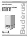
Gas wall hung Boiler condensing
Buderus 500 - 24/S
Buderus 500 - 24/C
Buderus 500 - 28/C
Please read thoroughly before attempting fault diagnosis
F
The boiler meets the basic requirements of the
appropriate standards and directives.
Conformity has been substantiated by the proper
documents which - together with the declaration of
conformity - are filed with the manufacturer.
Subject to technical modifications!
Constant development efforts may result in minor deviations
in illustrations, functional steps and technical data.
Updating the documentation
If you have suggestions for improvement or have found
discrepancies, please do not hesitate to contact us.
We reserve the right to make technical modifications
2
Buderus Ltd. • http://www.buderus-domestic.co.uk
Servicing manual Gas condensing boiler Buderus 500-24/S, 500-24/C and 500-28/C • Issued 02/2006
box 1
List of contents
box 2
Preface
These service instructions apply to:
Buderus wall-mounted condensing gas boilers
500 - 24/S, 500 - 24/C and 500 - 28/C.
1
General . . . . . . . . . . . . . . . . . . . . . . . . . . . . . . 4
2
Servicing manual user guide . . . . . . . . . . . 10
Model:
C13(x), C33(x), C53(x), C73(x)
3
Operation . . . . . . . . . . . . . . . . . . . . . . . . . . . 11
Type:
GB/IE II2H3P 20 mbar, 37 mbar
4
Function . . . . . . . . . . . . . . . . . . . . . . . . . . . . 14
Power rating: 230 VAC, 50 Hz, IP X4D
5
Symptoms . . . . . . . . . . . . . . . . . . . . . . . . . . . 17
The boiler unit consists of the following components:
6
Diagnosis . . . . . . . . . . . . . . . . . . . . . . . . . . . 21
– 500
Gas condensing boiler
– 28
Maximum output is 28 kW
Fuse rating:
1.25 Ampere slow blow
7
Actions . . . . . . . . . . . . . . . . . . . . . . . . . . . . . 38
– C
Combination boiler (with integrated hot water
supply)
8
Appendix . . . . . . . . . . . . . . . . . . . . . . . . . . . . 76
– S
System boiler.
9
Index . . . . . . . . . . . . . . . . . . . . . . . . . . . . . . . 77
Important general instructions for use
Only use the boiler in accordance with its designated use and
the service instructions. Installation, maintenance and repair
must be carried out by competent service engineers (e.g.
CORGI registered). Only use the boiler in conjunction with
the accessories and spare parts indicated in the installation,
maintenance and service instructions. Other accessories
and consumables may only be used if they are expressly
provided for the designated use and if system performance
and safety are not affected in any way.
The boiler is suitable for connection to fully pumped, sealed
water systems ONLY. Adequate arrangements for
completely draining the system by provision of draining
valves must be provided in the installation pipework.
Pipework from the boiler is routed downwards as standard,
but may be routed upwards behind the boiler using the wall
spacing frame.
Subject to technical modifications.
As a result of our policy of constant development, there may
be small differences between illustrations, functional steps
and technical data.
G. C. Aplliance No. :
Buderus 500-24/S
41-110-24
Buderus 500-24/C
41-110-04
Buderus 500-28/C
41-110-03
Other manuals available for this boiler are:
– user manual;
– installation and maintenance instructions;
– wall spacing frame instructions.
BENCHMARK' Log Book
All Buderus gas fired boilers now include an installation,
commissioning and service record log book.
The details of the log book will be required in the event of any
warranty work being requested.
Please complete the appropriate sections on completion of
the installation and commissioning.
REMEMBER: Please hand the log book back to the user.
We reserve the right to make technical modifications
Buderus Ltd. • http://www.buderus-domestic.co.uk
Servicing manual Gas condensing boiler Buderus 500-24/S, 500-24/C and 500-28/C • Issued 02/2006
3
1
1
General
General
box 3
Regulations and directives
It is a requirement that all gas appliances are installed and
serviced by a CORGI registered installer in accordance with
the regulations. Failure to service appliances correctly could
lead to prosecution. It is in your own interest, and that of
safety, to ensure the law is complied with.
Timber Framed Buildings
It is a requirement and in your own interest, and that of safety
that this boiler must be serviced by a CORGI registered
installer, in accordance with the relevant requirements of the
current Gas Safety (Installation and Use) Regulations,
The Building Regulations, current I.E.E. Wiring Regulations
and the relevant British Standard Codes of Practise.
Bathroom Installations
Detailed recommendations are contained in the following
British Standard Codes of Practice:
BS. 5440:1
Flues (for gas appliances of rated input not
exceeding 70 kW).
BS. 5440:2
Ventilation (for gas appliances of rated
input not exceeding 70 kW).
BS. 5449
Forced circulation hot water systems.
BS. 5546
Installation of gas hot water supplies for
domestic purposes (2nd. family Gases).
BS. 6798
Installation of gas fired hot water boilers of
rated input not exceeding 60 kW.
BS. 6891
Low pressure installation pipes.
BS. 7593: 1992: Code of practice for treatment of water in
domestic hot water central heating
systems.
IGE/UP/1b
Tightness testing and purging domestic
sized gas installations.
Health and & Safety Document No. 635.
The Electricity at Work Regulations, 1989.
The manufacturer's notes must not be taken, in any way, as
overriding statutory obligations.
The design and construction of the Buderus wall-mounted
condensing gas boiler conforms to the basic specifications
listed in the European directive governing gas-fired appliances 90/396/EEC, and with respect to EN 625, EN 483 and
EN 677.
I
NOTE:
Observe the corresponding technical rules and the
building supervisory and statutory regulations when
installing and operating the system.
H
WARNING!
Keep the burner-control unit housing CLOSED when
working on water-bearing components.
I
NOTE:
It is mandatory to clean and service the system once a
year. This includes an inspection of the entire system
to see if it is in full working order. Defects and faults
must be eliminated immediately.
I
NOTE:
When instructions aren’t followed, warranty expires.
I
NOTE:
Condensing boilers work more efficient if the
CH flow/return temperature is as low as possible.
We reserve the right to make technical modifications
4
If the boiler is to be fitted in a timber framed building it should
be fitted in accordance with the Institute of Gas Engineering
document IGE/UP/7:1998 and BS 5440:1.
This appliance is rated IP X4D.
The boiler may be installed in any room or internal space,
although particular attention is drawn to the requirements of
the current IEE (BS.7671) Wiring Regulations and, in Scotland, the electrical provisions of the building regulations
applicable in Scotland, with respect to the installation of the
boiler in a room or internal space containing a bath or
shower.
If the appliance is to be installed or serviced in a room
containing a bath or shower then, providing water jets are not
going to be used for cleaning purposes (as in communal
baths/showers), the appliance can be installed or serviced in
Zone 3, as detailed in BS.7671.
Compartment Installations
A compartment used to enclose the boiler should be
designed and constructed especially for this purpose.
An existing cupboard or compartment may be used, provided
that it is modified for the purpose.
In both cases, details of essential features of cupboard/
compartment design, including airing cupboard installation,
are to conform to the following:
BS 6798 (No cupboard ventilation is required - see 'Air
Supply' for details).
It is not necessary to have a purpose-provided air vent in the
room or internal space in which the boiler is installed. Neither
is it necessary to ventilate a cupboard or compartment in
which the boiler is installed, due to the low surface temperatures of the boiler casing during operation; therefore the
requirements of BS 6798, Clause 12, and BS 5440:2 may be
disregarded.
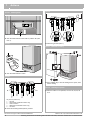
The permanent clearances required are:
in front:
8 mm
below:
21 mm
right side:
8 mm
left side:
8 mm
above:
21 mm
The position selected for installation MUST allow adequate
space for servicing in front of the boiler. See table below:
in front:
below:
right side:
left side:
above:
350 mm
180 mm
8 mm
8 mm
200 mm
In addition, sufficient space may be required to allow lifting
access to the wall mounting bracket.
Wall-mounted condensing gas combi boilers must only be
operated with Buderus purpose made gas systems, which
are certified for this type of boiler.
Buderus Ltd. • http://www.buderus-domestic.co.uk
Servicing manual Gas condensing boiler Buderus 500-24/S, 500-24/C and 500-28/C • Issued 02/2006
General
box 4
Observe the relevant standards, regulations and legislation
of the country or region of final use.
A
CAUTION!
Use this boiler for its intended purpose only.
A
DANGER!
Notes relating to the heating system water.
Thoroughly flush the system before it is filled with
water. Use only untreated water or water treatment
product such as Sentinel X100 to fill and top up the system. For more information about Sentinel call 0151 420
9563.
When using water treatment, only products suitable for
use with Buderus heat exchangers are permitted (e.g.
Sentinel X100). Your warranty is at risk if an incorrect
water treatment product is used in conjunction with this
appliance.
For more information, contact Buderus Technical Product Support Department.
It is most important that the correct concentration of the
water treatment product is maintained in accordance
with the manufacturer's instructions.
If the boiler is used in an existing system any unsuitable additives MUST be removed by thorough cleaning.
BS.7593:1992 details the steps necessary to clean a
domestic central heating system.
In hard water areas, treatment to prevent lime scale
may be necessary - however, the use of artificially softened water is NOT permitted.
Under no circumstances should the boiler be fired
before the system has been thoroughly flushed.
Do not use artificially softened water.
Only plastic pipework containing a polymeric barrier
should be used.
It is allowed to use copper for the first 600 mm.
I
NOTE:
Notes relating to domestic hot water
z The domestic hot water service must be in
accordance with BS 5546 and BS 6700.
z The boilers are suitable for connection to most types
of washing machine and dishwasher appliances.
z When connecting to suitable showers, ensure that:
a. The shower is capable of accepting mains
pressures and temperatures up to 65 °C.
b. The shower is ideally thermostatic or pressure
balancing.
z Where temporary hardness exceeds 150 mg/litre,
it is recommended that a proprietary scale reducing
device is fitted into the boiler cold supply with the
requirements of the local water company.
A
1
Hazard definitions and abbreviations
Hazard definitions
A
DANGER:
Indicates the presence of hazards that will cause
severe personal injury, death or substantial property
damage.
A
WARNING:
Indicates the presence of hazards that can cause
severe personal injury, death or substantial property
damage.
A
CAUTION:
Indicates presence of hazards that will or cause minor
personal injury or property damage.
I
NOTICE:
Indicates special instructions on installation, operation
or maintenance that are important but not related to
personal injury or property damage.
Abbreviations
AV
=
BCT =
BDV =
CB
=
CH
=
CHF =
CHR =
CT
=
CWDO =
DHW =
DV
=
E
=
L
=
LSV
=
MCW =
N
=
JB
=
PL
=
Prog =
PRV =
RT
=
RV
=
T
=
TRV =
WC
=
ZV
=
Air Vent
Buderus cylinder thermostat
Buderus diverter valve
Connection Block
Central Heating
Central Heating Flow
Central Heating Return
Cylinder Thermostat
Condensate water drainage outlet
Domestic Hot Water
Diverter Valve
Earth
Live
Lock Shield Valve
Mains Cold Water
Neutal
Junction Box / RTH Relay
Permanent Live
Programmer
Pressure relief valve (safety valve)
Room Thermostat
ModuLink 250 RF Receiver
Timer
Thermostatic Radiator Valve
Wiring Centre
Two Port Zone Valve
CAUTION!
Provision must be made to accommodate the expansion of DHW contained within the appliance, where a
back flow prevention device is fitted
BS. 67989: §5.4.3.
Safe handling of substances
No asbestos, mercury or CFCs are included in any part of the
boiler and its manufacture.
We reserve the right to make technical modifications
Buderus Ltd. • http://www.buderus-domestic.co.uk
Servicing manual Gas condensing boiler Buderus 500-24/S, 500-24/C and 500-28/C • Issued 02/2006
5
1
box 5
General
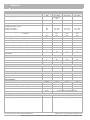
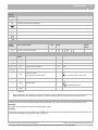
Technical specifications
Buderus
Unit
500-24/S
500-24/C
500-28/C
Hot water capacity (combination boilers)
kW
5.7 – 28.5
(with external
tank)
6.0 – 24.0
5.7 – 28.5
Rated thermal load for CH
kW
5.7 – 23.0
5.7 – 23.0
5.7 – 23.0
Rated thermal load for preparing DHW
kW
5.7 – 28.5
5.7 – 23.0
5.7 – 28.5
Rated heating capacity for system temperature
(modulating from 30° to 100°)
Heating curve 75/60 °C
Heating curve 40/30 °C
kW
kW
5.3 – 22.0
6.0 – 24.0
5.3 – 22.0
6.0 – 24.0
5.3 – 22.0
6.0 – 24.0
Seasonal efficiency (SEDBUK) for natural gas
for propane
%
%
90.3
92.3
90.3
92.3
90.3
92.3
Maximum gas consumption, hot water/tank
m3/h
3.02
2.43
3.02
Maximum gas consumption, heating
m3/h
2.43
2.43
2.43
Boiler efficiency (40/30°C) (lower value/upper value) (full load)
%
104 / 104
104 / 104
104 / 104
Boiler efficiency (40/30°C) (lower value) (partial load)
%
107
107
107
Boiler efficiency (40/30°C) (upper value) (partial load)
%
96.3
96.3
96.3
Boiler efficiency (75/60 °C) (lower value/upper value) (full load)
%
95.7 / 86.2
95.7 / 86.2
95.7 / 86.2
Boiler efficiency (75/60°C) (lower value/upper value) (partial load)
%
94.6 / 85.2
94.6 / 85.2
94.6 / 85.2
Chimney loss with burner shut down (standby heat loss) at nominal
thermal load
%
1.2
1.2
1.2
ΔT at residual head of 200 mbar
°C
<20
<20
<20
Maximum flow temperature
°C
80
80
80
Permitted system pressure
bar
1.0 – 3.0
1.0 – 3.0
1.0 – 3.0
l
7.5
7.5
7.5
bar
1.0
1.0
1.0
DHW flow rate at 35 °C rise
l/min
–
9.4
11.7
Supply pressure of hot water
bar
–
0.8 - 10.0
0.9 - 10.0
Adjustable DHW temperature
°C
–
40 - 60
40 - 60
Condensate outlet
Ø mm
21.5
21.5
21.5
CH flow/return (compression fitting)
Ø mm
22.0
22.0
22.0
MCW inlet / DHW outlet (compression fitting)
Ø mm
15.0
15.0
15.0
Gas on installation frame (compression fitting)
Ø mm
22.0
22.0
22.0
Pressure relief valve
Ø mm
Hot water circuit
Expansion vessel
Capacity of expansion vessel
Admission pressure of expansion vessel
Plate heat exchanger
Pipe connections
15 mm (adapter supplied with boiler)
Flue-gas connection
C13(x), C33(x), C53(x), C73(x)
Type of flue-gas connection (model)
Ø Flue gas pipe / combustion-air inlet
We reserve the right to make technical modifications
6
mm
60/100 (accessory)
Buderus Ltd. • http://www.buderus-domestic.co.uk
Servicing manual Gas condensing boiler Buderus 500-24/S, 500-24/C and 500-28/C • Issued 02/2006
General
box 5
1
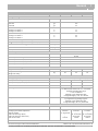
Technical specifications
Buderus
Unit
500-24/S
500-24/C
500-28/C
Flue-gas readings
Condensate water quantity, natural gas, 40/30 °C
l/h
1.6
Exhaust-fume mass-flow rate
Full load
Part-load
g/s
g/s
10.6
4.3
Exhaust-fume temperature, full load
Heating curve 75/60 °C
Heating curve 40/30 °C
°C
°C
77
55
Exhaust-fume temperature, partial load
Heating curve 75/60 °C
Heating curve 40/30 °C
°C
°C
60
35
CO2 full load, natural gas standard test gas G20
%
9,2
CO2 full load, natural gas standard test gas G31 propane
%
10.3
Standard emission factor NOx
ppm (mg/kWh)
<30
Standard emission factor CO
ppm (mg/kWh)
<22
Pa
75
Vac
230 (50 Hz)
Flow pressure available for use
Electrical specifications
Mains connection voltage
IP X4D
Electrical protection rating
Electrical power consumption, standby
W
4
Electrical power consumption, partial load
W
88
Electrical power consumption, full load
W
110
Dimensions and weight of boiler
height × width × depth
mm
780 × 460 × 330
780 × 460 × 330
780 × 460 × 330
Weight without casing
Weight with casing
kg
kg
30
33
31
34
31
34
Gas
II2H3P 20 mbar, 37 mbar (natural gas H and propane P)
Category of gas as per EN 437 for GB
Gas injector Ø natural gas H (G20)
mm
4.45
4.45
4.45
Gas injector Ø propane P (G31)
mm
3.45
3.45
3.45
423.072A
423.072A
423.072A
Venturi article number
Natural gas H
Delivered ready for operation, adjusted to Wobbe index
14.1 kWh/m3 (with reference to 15 °C, 1013 mbar),
applicable to Wobbe index range
11.3 to 15.2 kWh/m3.
Markings on gas classification plate:
Configured category: G 20 - 2E - 20 mbar
Propane P
Deemed suitable for use with propane after inspection
by a registered Corgi heating engineer.
Markings on gas classification plate:
Configured category: 3P G 31_30-50 mbar.
Other items
UP 15-50
Pump
Pump over-run time:
Heating system default adjustments
External cylinder
Plate heat exchanger (ECO)
Plate heat exchanger (warm start)
After service mode
We reserve the right to make technical modifications
5 minutes
30 - 40 seconds
–
–
1 minute
5 minutes
–
30 - 40 seconds
30 seconds
1 minute
5 minutes
–
30 - 40 seconds
30 seconds
1 minute
Buderus Ltd. • http://www.buderus-domestic.co.uk
Servicing manual Gas condensing boiler Buderus 500-24/S, 500-24/C and 500-28/C • Issued 02/2006
7
1
General
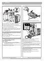
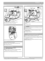
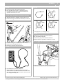
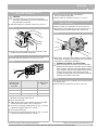
box 6
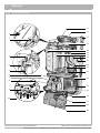
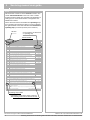
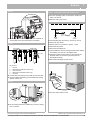
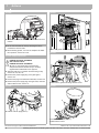
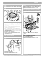
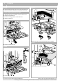
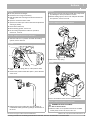
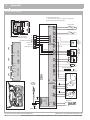
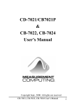
Overview Buderus 500
11
12
1
13
2
14
15
16
17
3
18
19
4
20
21
5
22
6
7
23
8
24
9
25
26
10
27
28
29
We reserve the right to make technical modifications
8
Buderus Ltd. • http://www.buderus-domestic.co.uk
Servicing manual Gas condensing boiler Buderus 500-24/S, 500-24/C and 500-28/C • Issued 02/2006
General
box 7
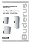
Key to terms
box 8
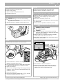
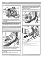
Item 1:
Ionisation electrode
Item 2:
Glow ignitor
A
Item 3:
Automatic air vent
Item 4:
Safety sensor
Item 5:
Clamp for heat exchanger cover
Item 6:
Plate heat exchanger
Item 7:
Condensate trap
Item 8:
Flow NTC sensor
Item 9:
DHW flow regulator
General points
WARNING!
DANGER OF FATAL ACCIDENT
FROM EXPLOSIVE FUMES
If you smell gas
z There is a danger of explosion.
z No naked lights. No smoking. DO NOT use a naked
light to detect possible leaks.
z DO NOT operate any device that is likely to produce
sparks.
z DO NOT operate electrical switches of any kind
(including telephones, plug-in devices and
doorbells)
z Shut off the gas supply at the main valve.
z Open doors and windows.
z Warn other occupants of the building (but DO NOT
use the house intercom or doorbells).
z Contact the gas supplier from a telephone located
outside the building.
z If you detect an audible gas leak, evacuate the
building immediately, prevent other persons from
entering, and notify the police and fire service
immediately (from a telephone OUTSIDE the
building).
Item 10: Pressure gauge
Item 11: Concentric flue gas adaptor
Item 12
1
Fan
Item 13: Frame
Item 14: Gas/Air unit
Item 15: Sight glass
Item 16: Gas valve
Item 17: Heat exchanger
Item 18: Gas supply pipe
Item 19: Identification plate of boiler
Item 20: Air silencer tube
Item 21: Flue gas pipe
H
WARNING!
A
CAUTION!
General information on maintenance work.
I
USER INSTRUCTIONS
Instructions for optimum usage, correct adjustment of
the boiler and other useful information.
A
CAUTION!
Use eye protection, inhalation protection, hearing,
gloves, shoes etc. on the right time.
Item 22: Flue gas safety temperature limiter (STL)
DANGER OF FATAL ACCIDENT
due to electric shock
Item 23: Pump 15-50
Item 24: Pressure relief valve discharge pipe
Item 25: Syphon
Item 26: Identification plate showing gas category
Item 27: Connection block
Item 28: DBA control panel
Item 29: RTH converter / junction box
We reserve the right to make technical modifications
Buderus Ltd. • http://www.buderus-domestic.co.uk
Servicing manual Gas condensing boiler Buderus 500-24/S, 500-24/C and 500-28/C • Issued 02/2006
9
2
2
Servicing manual user guide
Servicing manual user guide
box 9
This document consists of various sections. These in turn
contain subsections/boxes in the form of text or tables.
Subsections/boxes inside text and tables are identified by a
small grey box. Each subsection/box is assigned its own
identification number.
These subsections/boxes are divided into operating steps.
If an operating step involves the taking of a yes/no decision,
the right-hand side of the table indicates which subsection /
operating step you should proceed (cross reference).
Section
Cross reference to subsection
or operating step
Subsection/box
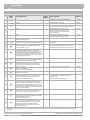
6
Diagnosis
box 24
step 28
Check the actuation of the servomotor of the internal three-way valve, see box 186.
step 29
Does the servomotor of the internal three-way valve start up correctly?
Yes:
No:
step 30
Replace the servomotor of the internal three-way valve, see box 191.
step 31
Check the power supply cable of the internal three-way valve, see box 192.
step 32
Is the power supply cable of the internal three-way valve in good condition?
Yes:
No:
step 33
Replace the cable loom (or the affected part thereof).
step 34
Check the movement of the servomotor of the Buderus 24V AC external three-way valve, see box 212.
step 35
Does the servomotor of the Buderus 24V AC external three-way valve operate correctly?
step 36
Check to ensure that the the Buderus 24V AC external three-way valve has been fitted correctly,
see box 228.
step 37
Has the Buderus 24V AC external three-way valve been fitted correctly?
Yes:
No:
Yes:
No:
step 38
Install the Buderus 24V AC external three-way valve correctly, see box 228.
step 39
Check to ensure that the Buderus 24V AC external three-way valve is actuated correctly,
see box 213 and box 229.
step 40
Does the Buderus 24V AC external three-way valve actuate correctly?
Yes:
No:
step 41
Replace the servomotor of the Buderus 24V AC external three-way valve, see box 218.
step 42
Check the wiring of the Buderus 24V AC external three-way valve, see box 221.
step 43
Is the wiring of the Buderus 24V AC external three-way valve in correct condition?
step 44
Replace the wiring of the Buderus 24V AC external three-way valve.
step 45
Check the drive mechanism of the Buderus 24V AC external three-way valve, see box 222.
step 46
Is the drive mechanism of the Buderus 24V AC external three-way valve working correctly?
step 47
Replace the internal components of the Buderus 24V AC external three-way valve, see box 225.
step 48
Check the wiring of the Buderus 24V AC external three-way valve between the connection box or
moving plug-and-socket connection and the control panel as per box 288.
Yes:
No:
Yes:
No:
o step 30
o step 31
o box 43
o box 42
o step 33
o box 43
o step 36
o step 39
o step 45
o step 38
o box 43
o step 41
o step 42
o box 43
o step 47
o step 44
o box 43
o box 42
o step 47
o box 43
box 25
On combi boiler supply: hot water available, but no heating operation.
On system boiler supply: no heating operation.
Hot water may be available, but no heating operation.
step 1
Check to ensure that the power supply cable to the RTH converter/Junction box has been installed correctly,
see box 286.
step 2
Is the 230V connection to the RTH converter/Junction box fitted correctly?
Yes:
No:
step 3
Correctly attach the switch live to terminal 1 and Neutral to terminal 2 on the 230V connector, see box 286.
step 4
Disconnect black leads from terminals 1 & 2 on the back of the DBA and test for continuity between the two
leads. No continuity check S/L and N connections are made correctly and that there is 230v between the two.
Replace RTH converter/Junction box.
Continuity reconnect the cables to terminals 1 & 2 and check the connections between the terminals and
the DBA.
We reserve the right to make technical modifications
24
o step 4
o step 3
o box 43
Buderus Ltd • http://www.buderus-domestic.co.uk
Servicing manual Gas condensing boiler Buderus 500-24/S, 500-24/C and 500-28/C • Issued 02/2005
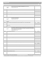
Operating step number
Explanation of this subject starts in this box.
The following boxes can be relevant as well.
We reserve the right to make technical modifications
10
Buderus Ltd. • http://www.buderus-domestic.co.uk
Servicing manual Gas condensing boiler Buderus 500-24/S, 500-24/C and 500-28/C • Issued 02/2006
Operation
3
3
Operation
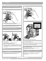
box 10
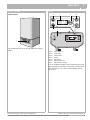
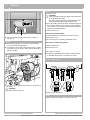
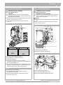
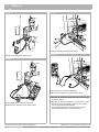
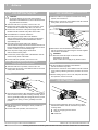
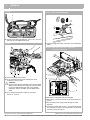
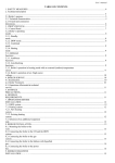
Operation
box 11
3
General points
2
4
5
6
7
1
1
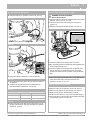
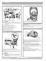
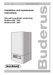
The central boiler can be run from the DBA control panel
(item 1).
item 1:
Mains switch 0/1
item 2:
Reset button
item 3:
Service button
item 4:
Display
item 5:
Menu button
item 6:
Adjusting arrow UP
item 7:
Adjusting arrow DOWN
You can navigate through the menu structure of the central
boiler using the service button, reset button, C-button and
D-button (item 2, 3, 5, 6 and 7) and the display (item 4),
box 12 to 14.
We reserve the right to make technical modifications
Buderus Ltd. • http://www.buderus-domestic.co.uk
Servicing manual Gas condensing boiler Buderus 500-24/S, 500-24/C and 500-28/C • Issued 02/2006
11
3
Operation
box 12
Normal Operation menu
step 1
[24] Current CH flow temperature, in °C. See also box 20.
step 2
Keep the D-button pressed.
step 3
[00] current DHW flow rate, in litres per minute
step 4
Continue with Normal Operation menu ?
step 5
Release the D-button.
step 6
Keep the C-button pressed.
step 7
[0h] Operating code. See also box 20
In this case: The boiler is ready for operation. No current heat requirement.
box 13
[24] Current CH flow temperature, in °C. See also box 20.
step 2
Activate service mode?
step 4
step 5
No:
→ step 5
→ step 1
→ step 4
Yes:
→ step 3
No:
→ step 1
Yes:
→ step 8
No:
→ step 6
Yes:
→ step 12
No:
→ step 10
Press the A-button once.
,24] As soon as the spanner symbol on the left-hand side of the display and the flame appear, the boiler will
run for 30 minutes in service mode. The maximum CH flow temperature (as configured in the “Settings” menu)
applies in this case.
Briefly press the C-button.
step 6
Partial-load service mode [lo] is activated. Check the gas/air ratio and ionisation current.
Adjust the gas/air ratio as required. See box 233 and box 143.
step 7
Exit partial-load service mode?
step 8
Press the A-button once.
step 9
Briefly press the C-button.
step 10
Full-load service mode ,hi] is activated. Check the working gas input pressure, or analyse the exhaust gas
accordingly box 230.
step 11
Exit full-load service mode?
step 12
Press the A-button once, or wait for service mode to expire (after 30 minutes).
step 13
Service mode is deactivated.
box 14
→ step 1
Settings menu
step 1
[24] Current CH flow temperature, in °C. See also box 17.
step 2
Open “Settings” menu?
step 3
Press the E-button once.
step 4
Is boiler a combination boiler with warm start ?
[pr# ( H / I ) Configured hot water mode. As soon as [pr# is displayed, you can verify the current hot
water mode, or adjust it as required. See also box 18.
step 6
Adjust configured hot water mode ?
We reserve the right to make technical modifications
Yes:
→ step 3
No:
→ step 1
→ step 4
step 5
12
→ step 6
Service Mode menu (no hot water is available during service-mode operation)
step 1
step 3
Yes:
Yes:
→ step 5
No:
→ step 9
Yes:
→ step 7
No:
→ step 8
Buderus Ltd. • http://www.buderus-domestic.co.uk
Servicing manual Gas condensing boiler Buderus 500-24/S, 500-24/C and 500-28/C • Issued 02/2006
Operation
box 14
3
Settings menu
step 7
Use single or multiple operation of the D- and C-buttons to activate and disable hot water mode.
[pr# ( H ): Hot water mode to ECO, [pr`( I ): Hot water mode to warm start.
step 8
Press the E-button once.
step 9
[60) As soon as the DHW temperature (in °C) appears on the display [60), you can read the current
DHW temperature, or adjust it as required. See also box 18.
step 10 Adjust DHW temperature ?
Yes:
→ step 11
No:
→ step 12
Yes:
→ step 15
No:
→ step 16
Yes:
→ step 19
No:
→ step 20
Yes:
→ step 22
No:
→ step 21
step 11 Lower: lower the DHW temperature with the D-button.
Higher: increase the DHW temperature with the C-button.
step 12 Press the E-button once.
step 13 [pr' ( K / L ) Configured heating mode. As soon as [pr' is displayed, you can verify the current
heating mode, or adjust it as required. See also box 18.
step 14 Adjust configured heating mode ?
step 15 Use single or multiple operation of the D- and C-buttons to activate and disable heating mode.
[pr. (K ): Heating mode on, [pr; (L ): Heating mode off.
step 16 Press the E-button once.
step 17 [80. Configure CH flow temperature, in °C. See also box 18. As soon as [80. is displayed, you can verify
the current CH flow temperature, or adjust it as required.
step 18 Adjust CH flow temperature ?
step 19 Lower: lower the CH flow temperature with the D-button.
Higher: increase the CH flow temperature with the C-button.
step 20 Has at least 10 seconds passed without a button being pressed and/or was mains supply interrupted ?
step 21 Press the E-button once.
→ step 1
step 22 Any adjustments that you have made will now be confirmed.
We reserve the right to make technical modifications
Buderus Ltd. • http://www.buderus-domestic.co.uk
Servicing manual Gas condensing boiler Buderus 500-24/S, 500-24/C and 500-28/C • Issued 02/2006
13
4
4
Function
Function
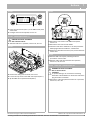
box 15
Boiler Functions
Start phase
step 1
Turn the mains switch to “ON”.
step 2
Turn the operating switch on the DBA control panel of the boiler to position “1“ (ON) – see also box 11.
step 3
Is a 3-way valve fitted?
Yes:
No:
step 4
Is the 3-way valve set to “hot water mode”?
Yes:
step 5
The Buderus 24V AC external 3-way valve is turned to “heating mode” in 7.5 seconds, while an internal 3-way
valve is turned to “heating mode” in 2 seconds.
No:
step 6
,00{ The display on the DBA control panel of the boiler is checked (maximum of one second).
step 7
[24] Current CH flow temperature, in °C. See also box 20.
step 8
→ step 4
→ step 6
→ step 5
→ step 6
C [0u] The boiler begins to warm up. Start of pre purge phase.
The fan runs for 15 seconds at about 60 % of maximum speed.
Checking phase
step 9
Has the pre purge been completed correctly?
Yes:
No:
step 10
→ step 11
→ step 10
Deal with fault. The error code, which is now displayed, can be found in box 20. Deal with the fault.
Operating phase
step 11
C [0h] Operating code. See also box 20. The boiler is ready for operation.
No current heat requirement.
step 12
Start of pump over-run time via the heating system.
The pump over-run time:
– via the heating system, factory-adjusted to 5 minutes;
– via the external reservoir, set to 30-40 seconds;
– via the plate heat exchanger (ECO), set to 30-40 seconds;
– via the plate heat exchanger (warm start), set to 30 seconds;
– after service mode, 1 minute.
step 13
Has the pump over-run time expired?
Yes:
No:
step 14
Is the boiler set to warm start for hot water and/or is an external storage-type water heater connected?
Yes:
No:
step 15
step 16
Is the plate heat exchanger triggered and/or is the temperature in the external storage-type water heater at least
5 °C below the temperature set at the DBA control panel?
Is there a current heat requirement from the (room) temperature controller?
Yes:
No:
Yes:
No:
step 17
Is the current CH flow temperature lower than 7 °C (frost protection)?
Yes:
No:
step 18
The pump stops.
step 19
Has the pump been out of use for more than 24 hours?
Yes:
No:
step 20
step 21
Is the plate heat exchanger triggered and/or is the temperature in the external storage-type water heater at least
5 °C below the temperature set at the DBA control panel?
Is there a current heat requirement from the (room) temperature controller?
Yes:
No:
Yes:
No:
We reserve the right to make technical modifications
14
→ step 18
→ step 14
→ step 15
→ step 16
→ step 28
→ step 16
→ step 46
→ step 19
→ step 62
→ step 18
→ step 23
→ step 20
→ step 28
→ step 21
→ step 46
→ step 22
Buderus Ltd. • http://www.buderus-domestic.co.uk
Servicing manual Gas condensing boiler Buderus 500-24/S, 500-24/C and 500-28/C • Issued 02/2006
Function
box 15
4
Boiler Functions
step 22 Is the current CH flow temperature lower than 7 °C (frost protection)?
Yes:
No:
→ step 62
→ step 23
step 23 The pump is run for 10 seconds in order to prevent it from seizing up.
step 24 Have 10 seconds elapsed?
Yes:
No:
step 25 Is the plate heat exchanger triggered and/or is the temperature in the external storage-type water heater at least
5 °C below the temperature set at the DBA control panel?
step 26 Is there a current heat requirement from the (room) temperature controller?
Yes:
No:
Yes:
No:
step 27 Is the current CH flow temperature lower than 7 °C (frost protection)?
Yes:
No:
→ step 18
→ step 25
→ step 28
→ step 26
→ step 46
→ step 27
→ step 62
→ step 24
step 28 The symbol “H" or “I" for hot water mode on the DBA control panel display lights up.
step 29 C [0c] The fan runs at 49 % of capacity.
The 3-way valve turns to the hot water setting for two seconds.
The glow ignitor is activated for two seconds.
step 30 C [0l] Ignition phase: The gas valve is opened. The glow ignitor is activated for one second, followed by
alternating half-second periods of inactivity and activity until five seconds have elapsed.
step 31 Does the ionisation current exceed 1.4 µA (microamperes) within 5 seconds?
Yes:
No:
→ step 32
→ step 72
step 32 C [=h] The boiler is in hot water mode. If there has been a power cut: The startup load on the boiler is 49%
for the first 13 seconds for the purposes of flow monitoring. It is then increased or decreased accordingly. The
symbol ” G “ lights up.
step 33 Is the temperature in the plate heat exchanger higher than the temperature entered via the DBA control panel?
Yes:
No:
step 34 Is the CH flow temperature 46 °C higher than the preset DHW temperature and/or higher than 93 °C?
Yes:
No:
→ step 39
→ step 34
→ step 35
→ step 32
step 35 C [0y] The gas valve is closed and the burner is shut down.
step 36 The symbol ” G “ goes out.
step 37 The fan stops after 30 seconds.
step 38 Is the CH flow temperature lower than the preset DHW temperature plus 35°C?
Yes:
No:
→ step 29
→ step 38
step 39 The gas valve is closed and the burner is shut down.
step 40 The symbol G goes out.
step 41 Start of pump over-run time via the cylinder.
Start of pre purge phase (10 seconds).
step 42 The fan stops.
step 43 C [0h] The pump stops.
step 44 The 3-way valve turns to the heating mode setting for two seconds.
The symbol “H" or “I" goes out.
step 45 Is there a current heat requirement from the (room) temperature controller?
Yes:
No:
→ step 46
→ step 19
step 46 The symbol K lights up.
step 47 C [0c] The fan runs at 49 % of capacity. The pump is started up.
The glow ignitor is activated for seven seconds.
step 48 C [0l] Ignition phase: The gas valve is opened.
We reserve the right to make technical modifications
Buderus Ltd. • http://www.buderus-domestic.co.uk
Servicing manual Gas condensing boiler Buderus 500-24/S, 500-24/C and 500-28/C • Issued 02/2006
15
4
Function
box 15
step 49
Boiler Functions
Does the ionisation current exceed 1.4 µA (microamperes)) within 5 seconds?
Yes:
No:
step 50
step 51
[-h] The boiler is in heating mode. The symbol G lights up.
The startup load on the boiler is 49% for the first 13 seconds for the purposes of flow monitoring.
It is then increased or decreased.
Is there a heating requirement from the (room) temperature controller?
Yes:
No:
step 52
step 53
Is the heat system flow temperature 6 °C higher than the target setting?
(The target setting is entered at the DBA control panel if room-temperature adjustment is required)
Yes:
No:
→ step 52
→ step 57
→ step 53
→ step 50
C [0y] The gas valve is closed and the burner is shut down.
step 54
The symbol G goes out.
step 55
The fan stops.
step 56
Is the CH flow temperature ≥ 6 °C lower than the target setting?
Yes:
No:
step 57
The symbol “K “ goes out.
step 58
C [0h] The gas valve is closed and the burner is shut down.
step 59
The symbol ” G “ goes out.
step 60
Start of pump over-run time via the heating system. The pump over-run time via the heating system is 5 minutes.
Start of the post purge phase of fan (10 seconds).
step 61
The fan stops.
step 62
The symbol “K “ lights up.
step 63
→ step 50
→ step 72
→ step 47
→ step 53
→ step 13
C [0c] The fan starts up. The pump is started up.
The glow ignitor is activated for seven seconds.
step 64
C [0l] Ignition phase: The gas valve is opened.
step 65
Does the ionisation current exceed 1.4 µA (microamperes) within 5 seconds?
Yes:
No:
step 66
C [-h] The symbol ” G “ lights up. The boiler is in heating mode.
step 67
Is the current CH flow temperature higher than 15 °C?
step 68
The symbol “K goes out.
step 69
C [0h] The gas valve is closed. The burner is shut down. The symbol G goes out.
Yes:
No:
step 70
Start of pump over-run time via the heating system. The pump over-run time via the heating system is 5 minutes.
Start of the post purge phase of fan (10 seconds).
step 71
The fan stops.
→ step 68
→ step 67
→ step 13
We reserve the right to make technical modifications
16
→ step 66
→ box 36
Buderus Ltd. • http://www.buderus-domestic.co.uk
Servicing manual Gas condensing boiler Buderus 500-24/S, 500-24/C and 500-28/C • Issued 02/2006
Symptoms
5
5
Symptoms
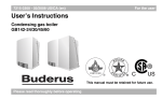
box 16
Display icons
Display
indication
Key to display indication
F
Service mode
G
Ionisation signal (flame monitoring)
H
Hot water mode “ECO” setting or hot water requirement
I
Hot water mode “warm start” setting or hot water requirement
J
Standby, hot water mode to “warm start”
K
Heating mode or heating requirement
L
Summer operation, no heating mode, hot water only
box 17
Display readings
Display
readings
Key to display reading
[24]
Unit
Current CH flow temperature
box 18
°C
Factory
default
setting
Range
[30]
–
Control-panel settings
Display
Setting
Button
Key to display setting
Unit
Range
1x A
<24]
Service mode
C
[lo]
Service mode, partial load
%
25
1x A C
[hi]
Service mode, full load
%
100
1x A
End service mode (or wait for 30 minutes)
E
[pr#
Hot water mode
Only applies to combi boilers 1)
E
[60)
DHW temperature
E
[pr'
Heating mode
E
[80.
CH flow temperature
[//]
1)
[80]
H = Hot water supply to ECO
I = Hot water mode to warm start
°C
40 – 60
K = Heating mode ON
L = Heating mode OFF
°C
30 – 80
= flashing
When it appears on the display at a system boiler, please connect a link between terminal 3 and 4 on the back side of the
DBA control panel (hot water cylinder sensor) or make sure that the hot water cylinder sensor is fitted securely.
box 19
Displaycodes
Normaly you see the current CH flow temperature. By pushing the "C"-button you will see the current operation code.
Blocking:
The boiler stops heating and will wait until the blocking is solved.
Locking:
Displaycode is blinking and also a blinking wrench "F" appears. The boiler stops heating and the pump is still running. The only
way to stop the locking is by pushing the reset "B" button.
We reserve the right to make technical modifications
Buderus Ltd. • http://www.buderus-domestic.co.uk
Servicing manual Gas condensing boiler Buderus 500-24/S, 500-24/C and 500-28/C • Issued 02/2006
17
5
Symptoms
box 20
Display codes
Display indication
z
Display
code
Key to display code
Reset
Other symptoms
required?
[//]
[//)
C
Standby
[0h]
Standby
C
[0h]
C
[0h]
Standby
C
:-h.
Operating phase:
The boiler is in heating mode.
C
:=h)
C
Diagnosis
No indication on DBA control panel display.
box 21
Hot water mode to “warm start”.
box 21
No (or insufficient) hot water, radiators, convectors,
etc. may be heated without current heat requirement.
box 22
Applies to boilers with hot water supply,
hot water available, no heating operation.
box 23
Applies to boilers without hot water supply,
no heating operation.
Applies to boilers with hot water supply,
hot water available, no heating operation.
box 24
Operating phase:
The boiler is in hot water mode. The symbol “ G ” lights up.
The heating circuit is warmed up without a heat
requirement.
box 22
[0a]
Operating phase:
Pump over-run time via the external cylinder/hot water
heater. The symbol “ G “ is off.
Pump over-run time:
Heating system factory default setting = 5 minutes;
for details of hot water and service mode see box 5.
The target room-temperature may not be reached.
box 25
C
[0a]
Operating phase:
The switch optimisation program is activated. This
program is activated if there is, more frequently than once
every 10 minutes, a heating water requirement from an
RC or ON/OFF control signal. This means that the boiler
cannot be restarted until at least 10 minutes have elapsed
since initial startup of the burner.
C
[0c]
Pre-operative phase:
The boiler prepares for burner startup whenever a heating
requirement or hot water requirement arises.
C
[0e]
Ready for operation:
The boiler is in ready mode. There is a current heat
requirement, but too much energy has been supplied.
C
[0h]
Standby for operation:
The boiler is in ready mode.
There is no current heat requirement.
Heat request, but no respons of the boiler
box 285
C
[0l]
Ignition phase:
The gas valve is activated.
[0u]
Startup phase:
The boiler starts up after activation of the mains power
supply or completion of a system reset. This code is
displayed for a maximum of 4 minutes.
Recycling phase:
The fan runs for 15 seconds at about 60% of
maximum speed.
The target room-temperature may not be reached.
box 26
The target room-temperature may not be reached.
box 27
No heating operation and no hot water.
box 28
C
"Extraction of residual fumes in boiler"
C
[0y]
Operating phase:
The flow sensor has detected that the current CH flow
temperature is higher than the temperature entered at the
control unit, or that it is higher than the CH flow temperature calculated according to heating requirements, or that
it is higher than the CH flow temperature calculated for the
purposes of hot water supply.
C
[0y]
Fault:
The flow sensor or safety sensor has detected that the
current CH flow temperature is higher than 95°C.
No
Yes
?1c]
Fault:
The flue-gas STL (fume-monitoring device) has detected
a temperature higher than 105°C.
The flue-gas STL is opened.
No
[2f]
Fault:
The flow sensor and safety sensor have, after burner
startup, not detected any temperature increase in the
heating water, or they have determined that the
temperature difference between The flow sensor and
safety sensor is too high.
C
1)
2)
box 27
1)
1) This error code may deactivate again automatically after a specific time (without reset). Heating and hot water are now available once more.
2) In the event of this malfunction, the pump is started up and remains in continuous operation in order to minimise the possibility of the heating system
freezing up.
We reserve the right to make technical modifications
18
Buderus Ltd. • http://www.buderus-domestic.co.uk
Servicing manual Gas condensing boiler Buderus 500-24/S, 500-24/C and 500-28/C • Issued 02/2006
Symptoms
box 20
5
Display codes
Display indication
z
Display
code
C
[2p]
Fault:
The flow sensor has detected a temperature increase, in
the heating system water, of over 5 °C/sec.
No
C
[3a]
Fault:
The tacho signal from the fan has failed during the
operating phase.
No
?3l]
Fault:
The tacho signal from the fan is not present during the preoperative or operating phase.
Yes
?3l]
Fault:
No current of air after a certain time.
Yes
?3y]
Fault:
The fan runs too slowly or too fast.
Yes
?4a]
Fault:
The flow sensor and safety sensor have detected a
CH flow temperature of over 105 °C.
Yes
?4e]
Fault:
The sensor test has failed.
Yes
Yes
?4l]
Fault:
The contacts of the flow sensor and safety sensor are
shorted to each other, or there is a short-circuit to earth
(ground), or the flow or safety sensor has detected a
CH flow temperature of above 130 °C.
?4p]
Fault:
The contacts of the flow sensor or safety sensor are
broken.
Yes
[6a]
Fault:
During the ignition phase, the system has detected an
insufficient ionisation current.
No
?6a]
Fault:
After four startup attempts, the system has detected an
insufficient ionisation current.
Yes
:6c]
Fault:
The system has detected an ionisation current before
burner startup.
Yes
?6c]
Fault:
An ionisation current has been measured as soon as the
burner shuts down.
Yes
[6l]
Fault:
The flame goes out during the operating phase.
No
?7c]
Fault:
The power supply was shut off during a crucial breakdown.
Yes
!88|
Operating phase:
Display test during startup phase:
The code is displayed for a maximum of 1 second.
?9a]
Fault:
The DBA control panel is defective.
Yes
?9f]
Fault:
The contacts of the gas valve have been broken.
Yes
?9h]
Fault:
The DBA control panel is defective.
Yes
?9l]
Fault:
The contacts of the gas valve have been broken.
Yes
?9l]
Fault:
The DBA control panel is defective.
Yes
C
C
Key to display code
Reset
Other symptoms
required?
Diagnosis
box 27
1)
box 29
1)
No heating operation and no hot water.
box 29
No heating operation and no hot water.
box 30
No heating operation and no hot water.
box 31
No heating operation and no hot water.
box 32
No heating operation and no hot water.
box 33
No heating operation and no hot water.
box 34
No heating operation and no hot water.
box 35
2)
2)
2)
2)
2)
2)
2)
box 36
1)
No heating operation and no hot water.
box 36
No heating operation and no hot water.
box 37
No heating operation and no hot water.
box 38
No heating operation and no hot water.
box 39
No heating operation and no hot water.
box 41
No heating operation and no hot water.
box 40
No heating operation and no hot water.
box 41
No heating operation and no hot water.
box 40
No heating operation and no hot water.
box 41
2)
2)
2)
1)
2)
2)
2)
2)
2)
2)
1) This error code may deactivate again automatically after a specific time (without reset). Heating and hot water are now available once more.
2) In the event of this malfunction, the pump is started up and remains in continuous operation in order to minimise the possibility of the heating system
freezing up.
We reserve the right to make technical modifications
Buderus Ltd. • http://www.buderus-domestic.co.uk
Servicing manual Gas condensing boiler Buderus 500-24/S, 500-24/C and 500-28/C • Issued 02/2006
19
5
Symptoms
box 20
Display codes
Display indication
z
Display
code
Key to display code
Reset
Other symptoms
required?
?9p]
Fault:
The DBA control panel is defective.
Yes
?9y]
Fault:
Short circuit in the gas valve.
Yes
?ef]
Fault:
The contacts of the KIM (EEPROM on the DBA control
panel circuit board) may be loose or short-circuited.
No
?e1]
Fault:
The DBA control panel is defective.
Yes
Diagnosis
No heating operation and no hot water.
box 41
2)
box 41
No heating operation and no hot water.
box 41
No heating operation and no hot water.
box 41
1)
2)
to
?e4]
?ea]
?ec]
C
[re]
Fault:
Reset is carried out.
This code appears after the reset button B is pressed for
5 seconds.
Applies only to a system-blocking error (flashing
display code)
1) This error code may deactivate again automatically after a specific time (without reset). Heating and hot water are now available once more.
2) In the event of this malfunction, the pump is started up and remains in continuous operation in order to minimise the possibility of the heating system
freezing up.
We reserve the right to make technical modifications
20
Buderus Ltd. • http://www.buderus-domestic.co.uk
Servicing manual Gas condensing boiler Buderus 500-24/S, 500-24/C and 500-28/C • Issued 02/2006
Diagnosis
6
6
Diagnosis
box 21
[\/\/\|
No indication on DBA control panel display.
step 1
Check to ensure that the power supply cable to the mains switch box has been installed correctly.
step 2
Is the power supply cable to the mains switch box correctly installed?
Yes:
No:
step 3
Install the power supply cable correctly, see box 54.
step 4
Check to ensure that the operating switch on the boiler DBA control panel is set to position “1” as per box 55.
step 5
Is the operating switch on the boiler DBA control panel set to “I” (ON)?
Yes:
No:
step 6
Turn the operating switch on the DBA control panel of the boiler to position “1” (ON), see box 55.
step 7
Check to the ensure that there is a 230V AC power supply at the mains switch.
step 8
Is there a 230V AC supply at the mains switch?
Yes:
No:
step 9
Deal with any problem in the electrical system.
step 10
Measure the resistance of the 230V AC power supply cable.
step 11
Is the resistance of the 230V AC power supply cable within the specified limits?
Yes:
No:
step 12
Replace the cable loom (or the affected part thereof).
step 13
Use a multimeter to check the fuse on the inside of the DBA control panel, see box 62 to 65.
step 14
Is the fuse working correctly?
Yes:
No:
step 15
Replace fuse, see box 62.
step 16
Is there any indication on the DBA control panel display?
Yes:
No:
step 17
Turn the operating switch on the DBA control panel of the boiler to position “0” (OFF), see box 43.
step 18
Disconnect the following boiler components from the electrical power supply:
→ step 4
→ step 3
→ box 42
→ step 7
→ step 6
→ box 42
→ step 10
→ step 9
→ box 42
→ step 22
→ step 21
→ box 42
→ box 41
→ step 15
→ box 42
→ step 17
– pump, see box 92
– fan, see box 71, item 1.
step 19
Check the fuse again for correct functioning. Use a multimeter to check the fuse on the inside of the DBA
control panel, see box 62.
step 20
Is the fuse working correctly?
Yes:
No:
step 21
Replace fuse again, see box 62.
step 22
Turn the operating switch on the DBA control panel of the boiler to position “1” (ON), see box 55.
step 23
Is there any indication on the DBA control panel display?
Yes:
No:
step 24
Use a multimeter to check the power supply cables of the pump (box 95), the fan (box 69) and the glow ignitor
(box 137) for signs of short circuiting.
step 25
Are the cables in order?
Yes:
No:
step 26
Replace the cable harness (or the affected part thereof).
Replace fuse again, see box 62.
step 27
Turn the operating switch on the DBA control panel of the boiler to position “0” (OFF), see box 43.
step 28
Connect the power supply plug of the pump in reverse.
step 29
Turn the operating switch on the DBA control panel of the boiler to position “1” (ON), see box 55.
We reserve the right to make technical modifications
→ step 22
→ step 21
→ step 27
→ step 24
→ step 27
→ step 26
→ box 42
Buderus Ltd. • http://www.buderus-domestic.co.uk
Servicing manual Gas condensing boiler Buderus 500-24/S, 500-24/C and 500-28/C • Issued 02/2006
21
6
Diagnosis
box 21
step 30
Is there any indication on the DBA control panel display?
Yes:
No:
step 31
Replace the pump, see box 101.
step 32
Replace fuse again, see box 62.
step 33
Turn the operating switch on the DBA control panel of the boiler to position “0” (OFF), see box 43.
step 34
Connect the power supply plug of the fan in reverse.
step 35
Turn the operating switch on the DBA control panel of the boiler to position “1” (ON), see box 55.
step 36
Is there any indication on the DBA control panel display?
Yes:
No:
step 37
Replace fan, see box 76.
step 38
Replace fuse again, see box 62.
→ step 33
→ step 31
→ step 32
→ step 33
→ box 42
→ step 37
→ step 38
→ box 42
box 22
No (or insufficient) hot water, radiators, convectors, etc. may be heated without current heat requirement.
step 1
Set the operating switch on the boiler DBA control panel to position “0“ (OFF), see box 43, and set the other
DBA control panel operating switch to position “1“ (ON), see box 55.
step 2
Open a hot water tap.
step 3
Check that the hot water pipe directly beneath the (external) storage-type water heater warms up.
step 4
Does the pipe warm up (to approx. 60 °C)?
Yes:
No:
step 5
The cause of this fault does not lie with the boiler, but with the mains water supply. Check to see if the
MCW inlet and DHW outlet have been incorrectly connected to the (external) storage-type water heater.
step 6
Are the pipes connected correctly?
Yes:
No:
step 7
Connect the pipeworks correctly.
step 8
Close the shut-off valve in the MCW inlet and open a hot water tap at random to see if water is still flowing.
step 9
Is this the case?
Yes:
No:
step 10
The cause is a defective (thermostat-controlled) mixer tap, a thermostat-controlled mixer valve or a short
circuit between the hot- and cold water circuits.
step 11
Check to see if any other external part of the drinking-water system is a possible cause.
step 12
Are such items detected?
Yes:
No:
step 13
Place the affected components out of service.
step 14
Check
→ step 5
→ step 39
→ step 8
→ step 7
→ box 42
→ step 10
→ step 11
→ box 42
→ step 13
→ box 42
→ box 42
to ensure that the pre-adjusted setting corresponds to the hot water [60) box 14 supply.
to ensure that the DHW temperature is adjusted to a high enough setting, see box 61.
to see if the hot water supply has been shut off by the control system (ModuLink 250 RF).
step 15
Are the adjustment settings in order?
Yes:
No:
step 16
Adjust the settings.
step 17
Check to see if the “hot water mode” indicator (H) or (I) lights up on the display, see box 11.
step 18
Does the “hot water mode” indicator (H) or (I) light up?
Yes:
No:
step 19
→ step 25
→ step 19
Check the turbine flow-meter, see box 104, or DWH temperature sensor of any external storage-type water
heater that might be fitted.
We reserve the right to make technical modifications
22
→ step 17
→ step 16
→ box 42
Buderus Ltd. • http://www.buderus-domestic.co.uk
Servicing manual Gas condensing boiler Buderus 500-24/S, 500-24/C and 500-28/C • Issued 02/2006
Diagnosis
6
box 22
step 20
Is the turbine flow-meter working correctly (along with DHW temperature sensor of any external storage-type
water that might be fitted)?
step 21
Replace the turbine flow-meter, or DHW temperature sensor of any external storage-type water heater that
might be fitted.
step 22
Check the cable of the turbine flow-meter, see box 112, or cable of the DHW temperature sensor of any
external storage-type water heater that might be fitted.
step 23
Is the cable correctly connected and free of damage?
Yes:
No:
Yes:
No:
step 24
Replace the cable loom (or the affected part thereof).
step 25
Check to ensure that the boiler starts up to supply hot water, see box 15.
step 26
Does the boiler start up?
Yes:
No:
step 27
Interpret current display codes box 20 and deal with fault.
step 28
Check to ensure that the tap flow rate is correctly adjusted, see box 180.
step 29
Is the tap flow rate correctly adjusted?
Yes:
No:
step 30
Correctly adjust the tap flow rate, see box 180.
step 31
Is an internal 3-way valve fitted?
Yes:
No:
step 32
Check the movement of the servomotor of the Buderus 24V AC external 3-way valve, see box 211.
step 33
Does the servomotor of the Buderus 24V AC external 3-way valve move correctly?
Yes:
No:
step 34
Check the movement of the servomotor of the internal 3-way valve, see box 181..
step 35
Does the servomotor of the internal 3-way valve move correctly?
Yes:
No:
step 36
Check to ensure that the the Buderus 24V AC external 3-way valve has been fitted correctly,
see box 227.
step 37
Has the Buderus 24V AC external 3-way valve been fitted correctly?
Yes:
No:
step 38
Fit the Buderus 24V AC external 3-way valve in the correct way, see box 227.
step 39
Check the drive mechanism of the internal 3-way valve, see box 195.
step 40
Is the drive mechanism of the internal 3-way valve working correctly?
Yes:
No:
step 41
Replace the drive mechanism of the internal 3-way valve, see box 198.
step 42
Check the circulation for debris, see box 97.
step 43
Is there any debris in the pump?
Yes:
No:
step 44
Clean the pump, see box 97.
step 45
The following components must be checked for soiling and/or damage:
- combustion-air inlet pipework
- heat exchanger
- flue-gas pipework.
step 46
Are the above-mentioned components clean and free of damage?
Yes:
No:
step 47
Clean and/or replace the corresponding components.
We reserve the right to make technical modifications
→ step 22
→ step 21
→ box 42
→ box 41
→ step 24
→ box 42
→ step 28
→ step 27
→ box 42
→ step 31
→ step 30
→ step 34
→ step 32
→ step 36
→ step 63
→ step 39
→ step 57
→ step 69
→ step 38
→ box 42
→ step 42
→ step 41
→ box 42
→ step 44
→ step 45
→ box 42
→ step 48
→ step 47
→ box 42
Buderus Ltd. • http://www.buderus-domestic.co.uk
Servicing manual Gas condensing boiler Buderus 500-24/S, 500-24/C and 500-28/C • Issued 02/2006
23
6
Diagnosis
box 22
step 48
Check the standing and working gas pressures, see box 230.
step 49
Are the standing and working pressures correct?
Yes:
No:
step 50
If the standing and working gas input pressures are not detected, consult your gas utility company.
step 51
Check the gas/air ratio, see box 233.
step 52
Is the gas/air ratio correct?
Yes:
No:
step 53
Adjust the gas/air ratio, see box 233.
step 54
Check the plate heat exchanger or the external hot water cylinder for furring.
step 55
Is the plate heat exchanger or hot water cylinder furred up?
Yes:
No:
step 56
Decalcify the plate heat exchanger and/or hot water cylinder, see from box 269.
step 57
3-way valve: Check the startup of the servomotor of the internal 3-way valve, see box 181 and box 185.
step 58
Does the servomotor of the internal 3-way valve start up correctly?
Yes:
No:
step 59
Replace the servomotor of the internal 3-way valve, see box 190.
step 60
Check the wiring of the internal 3-way valve, see box 191.
step 61
Is the cable correctly connected and free of damage?
Yes:
No:
step 62
Replace the cable loom (or the affected part thereof).
step 63
Check to ensure that the Buderus 24V AC external 3-way valve has actuated correctly,
see box 212 and box 228 parts 1 and 2.
step 64
Does the Buderus 24V AC external 3-way valve actuate correctly?
Yes:
No:
step 65
Replace the servomotor of the Buderus 24V AC external 3-way valve, see box 217.
step 66
Check the wiring of the Buderus 24V AC external 3-way valve, see box 220.
step 67
Is the wiring of the Buderus 24V AC external 3-way valve in correct condition?
Yes:
No:
step 68
Replace the wiring of the Buderus 24V AC external 3-way valve.
step 69
Check the drive mechanism of the Buderus 24V AC external 3-way valve, see box 221.
step 70
Is the drive mechanism of the Buderus 24V AC external 3-way valve working correctly?
Yes:
No:
step 71
Replace the drive mechanism of the Buderus 24V AC external 3-way valve, see box 221.
step 72
Check the wiring of the Buderus 24V AC external 3-way valve between the connection box or moving plugand-socket connection and the motor of the Buderus 24V AC external 3-way valve, see box 287.
step 73
Is the wiring in order?
Yes:
No:
step 74
Replace the cable loom (or the affected part thereof).
→ step 51
→ step 50
→ box 42
→ step 54
→ step 53
→ box 42
→ step 56
→ box 41
→ box 42
→ step 59
→ step 60
→ box 42
→ box 41
→ step 62
→ box 42
→ step 65
→ step 66
→ box 42
→ step 71
→ step 68
→ box 42
→ step 42
→ step 71
→ box 41
→ step 74
→ box 42
box 23
On combi boilers: hot water available, but no heating operation.
On system boilers: no heating operation.
Hot water may be available, but no heating operation.
step 1
Check to ensure that the power supply cable to the mains switch box has been installed correctly, see box 54.
We reserve the right to make technical modifications
24
Buderus Ltd. • http://www.buderus-domestic.co.uk
Servicing manual Gas condensing boiler Buderus 500-24/S, 500-24/C and 500-28/C • Issued 02/2006
Diagnosis
6
box 23
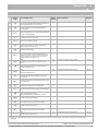
step 2
Check to ensure that the preset room temperature or heating configuration of the Buderus controls or ON/
OFF controller has been adjusted to a high enough setting (see operating instructions).
step 3
Is the preset room temperature or heating configuration of the Buderus controls or ON/OFF controller
adjusted to a high enough setting?
step 4
Adjust the preset room temperature controller or heating configuration of the Buderus controls or
ON/OFF controller to a higher setting (see operating instructions).
step 5
Check to see if the “heating requirement” (K) indicator lights up on the display, see box 11.
step 6
Does the “heating requirement” (K) indicator light up?
Yes:
No:
Yes:
No:
step 7
Check the Buderus controls or ON/OFF controller as per box 177.
step 8
Is the Buderus controls or ON/OFF controller working correctly?
Yes:
No:
step 9
Replace the thermostat cable.
step 10
Replace the Buderus controls or ON/OFF controller.
step 11
Check to ensure that the CH flow temperature at the DBA control panel or on the Buderus controls or ON/
OFF controller is adjusted to a high enough setting as per box 14 and box 61 .
step 12
Is the CH flow temperature adjusted to a high enough setting?
Yes:
No:
step 13
Are enough thermostatic valves open on the radiators, convectors, etc?
Yes:
No:
step 14
Open more thermostatic valves on the radiators, convectors, etc.
step 15
Adjust the CH flow temperature as per box 14 and box 61. Ensure that the Buderus controls or
ON/OFF controller are calling for a heating demand.
step 16
Check to ensure that the CH flow temperature is correctly adjusted, see box 14.
step 17
Is the CH flow temperature adjusted to a high enough setting?
Yes:
No:
step 18
Adjust the CH flow temperature to a higher setting, see box 14.
step 19
Is the CH flow temperature of the boiler sufficient to heat the building?
Yes:
No:
step 20
Install a larger boiler.
step 21
Is there a hot water supply?
Yes:
No:
step 22
Is an internal 3-way valve fitted?
Yes:
No:
step 23
Check the movement of the servomotor of the internal 3-way valve, see box 181.
step 24
Does the servomotor of the internal 3-way valve move correctly?
Yes:
No:
step 25
Check the drive mechanism of the internal 3-way valve, see box 195.
step 26
Is the drive mechanism working correctly?
Yes:
No:
step 27
Replace the drive mechanism of the internal 3-way valve, see box 198.
step 28
Check the actuation of the servomotor of the internal 3-way valve, see box 185.
step 29
Does the servomotor of the internal 3-way valve start up correctly?
Yes:
No:
We reserve the right to make technical modifications
→ step 5
→ step 4
→ box 42
→ step 11
→ step 7
→ step 9
→ step 10
→ box 42
→ box 42
→ step 13
→ step 15
→ step 16
→ step 14
→ box 42
→ box 42
→ step 19
→ step 18
→ box 42
→ step 21
→ step 20
→ box 42
→ step 22
→ box 41
→ step 23
→ step 34
→ step 25
→ step 28
→ box 42
→ step 27
→ box 42
→ step 30
→ step 31
Buderus Ltd. • http://www.buderus-domestic.co.uk
Servicing manual Gas condensing boiler Buderus 500-24/S, 500-24/C and 500-28/C • Issued 02/2006
25
6
Diagnosis
box 23
step 30
Replace the servomotor of the internal 3-way valve, see box 190.
step 31
Check the power supply cable of the internal 3-way valve, see box 191.
step 32
Is the power supply cable of the internal 3-way valve in good condition?
→ box 42
Yes:
No:
step 33
Replace the cable loom (or the affected part thereof).
step 34
Check the movement of the servomotor of the Buderus 24V AC external 3-way valve, see box 211.
step 35
Does the servomotor of the Buderus 24V AC external 3-way valve operate correctly?
Yes:
No:
step 36
Check to ensure that the the Buderus 24V AC external 3-way valve has been fitted correctly,
see box 227.
step 37
Has the Buderus 24V AC external 3-way valve been fitted correctly?
Yes:
No:
step 38
Install the Buderus 24V AC external 3-way valve correctly, see box 227.
step 39
Check to ensure that the Buderus 24V AC external 3-way valve is actuated correctly,
see box 212 and box 228.
step 40
Does the Buderus 24V AC external 3-way valve actuate correctly?
Yes:
No:
step 41
Replace the servomotor of the Buderus 24V AC external 3-way valve, see box 217.
step 42
Check the wiring of the Buderus 24V AC external 3-way valve, see box 220.
step 43
Is the wiring of the Buderus 24V AC external 3-way valve in correct condition?
Yes:
No:
step 44
Replace the wiring of the Buderus 24V AC external 3-way valve.
step 45
Check the drive mechanism of the Buderus 24V AC external 3-way valve, see box 221.
step 46
Is the drive mechanism of the Buderus 24V AC external 3-way valve working correctly?
Yes:
No:
step 47
Replace the internal components of the Buderus 24V AC external 3-way valve, see box 224.
step 48
Check the wiring of the Buderus 24V AC external 3-way valve between the connection box or moving plugand-socket connection and the DBA control panel as per box 287.
→ box 41
→ step 33
→ box 42
→ step 36
→ step 39
→ step 45
→ step 38
→ box 42
→ step 41
→ step 42
→ box 42
→ step 47
→ step 44
→ box 42
→ box 41
→ step 47
→ box 42
box 24
On combi boiler supply: hot water available, but no heating operation.
On system boiler supply: no heating operation.
Hot water may be available, but no heating operation.
step 1
Check to ensure that the power supply cable to the RTH converter/Junction box has been installed correctly,
see box 285.
step 2
Is the 230V connection to the RTH converter/Junction box fitted correctly?
Yes:
No:
step 3
Correctly attach the switch live to terminal 1 and Neutral to terminal 2 on the 230V connector, see box 285.
step 4
Disconnect black leads from terminals 1 & 2 on the back of the DBA and test for continuity between the two
leads.
No continuity check S/L and N connections are made correctly and that there is 230v between the two.
Replace RTH converter/Junction box.
Continuity reconnect the cables to terminals 1 & 2 and check the connections between the terminals and
the DBA.
step 5
Is the volt free connection to the RTH converter/Junction box fitted correctly?
→ box 42
Yes:
No:
step 6
→ step 6
→ step 8
Check to ensure that the connections of the external control unit are attached to terminal 1 and 2 of the
connection block, indicated by a clock inside a rectangle, see box 286 and box 285 (item 3).
We reserve the right to make technical modifications
26
→ step 4
→ step 3
Buderus Ltd. • http://www.buderus-domestic.co.uk
Servicing manual Gas condensing boiler Buderus 500-24/S, 500-24/C and 500-28/C • Issued 02/2006
Diagnosis
6
box 24
step 7
Is there a permanent link between terminal 1 and 2 on the volt free connecter?
Yes:
No:
step 8
Check the cable connection between the RTH converter/Junction box and terminal 1 and 2 on the DBA.
step 9
Check the external cable connections and control devices.
step 10
Has the malfunction been repaired?
Yes:
No:
→ step 8
→ step 9
→ box 42
→ box 42
→ box 41
box 25
C [0a]
The switch optimisation program is activated. This program is activated if there is,
more frequently than once every 10 minutes, a heating water requirement from an
Buderus controller or ON/OFF controller signal. This means that the boiler cannot
be restarted until at least 10 minutes have elapsed since initial startup of the burner.
Operating code
step 1
Check to ensure that the connections of the control device are correctly fitted at the boiler and control device.
step 2
Is the control device connected correctly?
Yes:
No:
step 3
Connect the control device correctly.
step 4
Carry out a visual examination where possible, and use a multimeter to check the electrical resistance of the
thermostat lead. Check for breakages and loose contacts.
step 5
Is the thermostat cable in good condition?
Yes:
No:
step 6
Replace the thermostat cable.
step 7
Check to ensure that enough thermostatic valves are open on the radiators, convectors, etc.
step 8
Are enough thermostatic valves open on the radiators, convectors, etc?
Yes:
No:
step 9
Open more thermostatic valves on the radiators, convectors, etc.
step 10
Attempt to rectify the fault by temporarily replacing the room thermostat or external temperature-dependent
controller.
step 11
Has the malfunction been repaired?
Yes:
No:
→ step 4
→ step 3
→ box 42
→ step 7
→ step 6
→ box 42
→ step 10
→ step 9
→ box 42
→ box 42
→ box 41
box 26
C [0y]
The flow NTC sensor has detected that the current CH flow temperature is higher
than the temperature entered at the control unit, or that it is higher than the CH flow
temperature calculated according to heating requirements, or that it is higher than
the CH flow temperature calculated for the purposes of hot water supply.
Operating code
step 1
Check to ensure that the CH flow temperature at the DBA control panel is higher than that entered at the
controller, see box 61.
step 2
Is the CH flow temperature at the DBA control panel adjusted correctly?
Yes:
No:
step 3
Adjust the CH flow temperature at the DBA control panel to a higher setting, see box 61.
step 4
Check to ensure that enough thermostatic valves are open on the radiators, convectors, etc.
step 5
Are enough thermostatic valves open on the radiators, convectors, etc?
Yes:
No:
step 6
Open more thermostatic valves on the radiators, convectors, etc.
step 7
Check to see if a hot tap or taps have been opened on brief, consecutive occasions.
We reserve the right to make technical modifications
→ step 4
→ step 3
→ box 42
→ step 7
→ step 6
→ box 42
Buderus Ltd. • http://www.buderus-domestic.co.uk
Servicing manual Gas condensing boiler Buderus 500-24/S, 500-24/C and 500-28/C • Issued 02/2006
27
6
Diagnosis
box 26
step 8
Have a hot water tap or taps been opened briefly and consectutively on several occasions?
Yes:
No:
step 9
Inform the user that the fault has been caused by opening hot taps on many brief, consecutive occasions.
step 10
Check the electrical resistance of the DHW temperature sensor, see box 104.
step 11
Is the electrical resistance of the DHW temperature sensor in order?
Yes:
No:
step 12
→ step 9
→ box 15
→ box 42
→ box 41
→ step 12
Replace the DHW temperature sensor.
box 27
C [0y]
C [2f]
The flow NTC sensor or safety sensor has detected that the current CH flow
temperature is higher than 95 °C.
Blocking boiler-fault code
The flow NTC sensor and safety sensor have not, after burner startup, detected any
temperature increase in the heating system water, or the temperature difference
between the flow NTC sensor and safety sensor is excessive.
Blocking boiler-fault code
C [2p]
[4a]
[4e]
step 1
The flow NTC sensor has detected a temperature increase in the heating system
water of more than 5 °C/sec.
Blocking boiler-fault code
The flow NTC sensor and safety sensor have detected a CH flow temperature of over
105 °C.
Locking boiler-fault code
Short circuit between flow NTC sensor or safety sensor.
Locking boiler-fault code
Are the servicing valves open?
Yes:
No:
step 2
Open the servicing valves, see box 53.
step 3
Is the pressure in the heating system at least 1 bar?
Yes:
No:
step 4
Fill and vent the heating system, see box 52.
step 5
Are enough thermostatic valves open on the radiators, convectors, etc?
Yes:
No:
step 6
Open more thermostatic valves on the radiators, convectors, etc.
step 7
Check the flow NTC sensor and safety sensor, see box 104.
step 8
Are the flow NTC sensor and safety sensor in order?
Yes:
No:
step 9
Replace the flow NTC sensor or safety sensor, see box 116.
step 10
Check the cable between the flow NTC sensor or safety sensor for short circuits, see box 112.
step 11
Check the pump, see box 89 to 100.
step 12
Is the pump working correctly?
Yes:
No:
step 13
Replace the pump, see box 101.
step 14
Check to ensure that the internal by-pass valve in the boiler or the external overflow valve in the heating
system are working correctly. Possible to adjust external overflow valve to max. 25 kPa (if fitted).
step 15
Is the by-pass valve working correctly?
Yes:
No:
We reserve the right to make technical modifications
28
→ step 3
→ step 2
→ step 5
→ step 4
→ step 7
→ step 6
→ box 42
→ step 10
→ step 9
→ box 42
→ step 14
→ step 13
→ box 41
→ step 14
Buderus Ltd. • http://www.buderus-domestic.co.uk
Servicing manual Gas condensing boiler Buderus 500-24/S, 500-24/C and 500-28/C • Issued 02/2006
Diagnosis
6
box 27
step 16
→ box 42
Replace the by-pass valve.
box 28
[1c]
The flue-gas STL (fume-monitoring device) has detected a temperature higher than
105°C. The flue-gas STL is open.
Locking boiler-fault code
step 1
Check to ensure that the restrictor baffle has been installed as per box 261, item 1.
step 2
Has the restrictor baffle been fitted?
Yes:
No:
step 3
Fit the restrictor baffle, see box 261, item 1.
step 4
Check the entire system of flue gas pipe for restrictions.
step 5
Is the entire system of flue gas pipe in full working order?
Yes:
No:
step 6
Deal with restriction.
step 7
Check the flue-gas STL, see box 120.
step 8
Is the flue-gas STL working correctly?
Yes:
No:
step 9
Replace the flue-gas STL, see box 129.
step 10
Check the wiring of the flue-gas STL, see box 126.
step 11
Is the wiring of the flue-gas STL in full working order?
Yes:
No:
step 12
Replace the cable loom (or the affected part thereof).
→ step 4
→ step 3
→ box 42
→ step 7
→ step 6
→ box 42
→ step 10
→ step 9
→ box 41
→ step 12
→ box 42
box 29
C [3a]
[3l]
The tacho signal from the fan has failed during the operating phase.
Blocking boiler-fault code
The tacho signal from the fan is not present during the pre-operative or operating
phase.
Locking boiler-fault code
step 1
Check to ensure that both plug-and-socket connections of the fan are correctly fitted, see box 246, item 1.
step 2
Are the plug-and-socket connections fitted correctly?
Yes:
No:
step 3
Reconnect the plug-and-socket connection of the fan.
step 4
Check fan, 230V AC supply, see box 66 or box 287.
step 5
Does activation take place correctly?
Yes:
No:
step 6
Check the power supply cable of the fan (230V AC), see box 69.
step 7
Is the power supply cable of the fan in full working order?
Yes:
No:
step 8
Replace the cable loom (or the affected part thereof).
step 9
Check tacho cable of fan, see box 73.
step 10
Is the tacho cable in full working order?
Yes:
No:
step 11
Replace the cable loom (or the affected part thereof).
step 12
Check to ensure that the mains voltage at the earthed (grounded) plug is between 195V and 253V AC.
We reserve the right to make technical modifications
→ step 4
→ step 3
→ box 42
→ step 9
→ step 6
→ box 41
→ step 8
→ box 42
→ step 12
→ step 11
→ box 42
Buderus Ltd. • http://www.buderus-domestic.co.uk
Servicing manual Gas condensing boiler Buderus 500-24/S, 500-24/C and 500-28/C • Issued 02/2006
29
6
Diagnosis
box 29
step 13
Is the mains voltage sufficient?
Yes:
No:
step 14
The cause of the fault lies in the electrical system.
step 15
Replace fan, see box 76.
step 16
Has the malfunction been repaired?
Yes:
No:
→ step 15
→ step 14
→ box 42
→ box 42
→ box 41
box 30
[3l]
No current of air after a certain time.
Locking boiler-fault code
step 1
Attempt to rectify the fault by temporarily replacing the fan, see box 76.
step 2
Has the malfunction been repaired?
Yes:
No:
→ box 42
→ box 41
box 31
[3y]
The fan runs too slowly or too fast.
Locking boiler-fault code
step 1
Check the plug-and-socket connection of the fan tacho cable.
This is the narrow plug, see box 78, item 2.
step 2
Is the plug-and-socket connection in full working order?
Yes:
No:
step 3
Reconnect the plug-and-socket connection, see box 78, item 2.
step 4
Check tacho cable of fan, see box 73.
step 5
Is the tacho cable in full working order?
Yes:
No:
step 6
Replace the tacho cable.
step 7
Check to ensure that the mains voltage at the earthed (grounded) plug is between 195V and 253V AC.
step 8
Is the mains voltage sufficient?
Yes:
No:
step 9
The cause of the fault lies in the electrical system.
step 10
Check to see if there is a restriction in the fan, burner, heat exchanger or flue-gas system.
step 11
Is there a restriction?
Yes:
No:
step 12
Deal with restriction.
step 13
Check to see if there is a second fan in the flue gas pipe or air inlet system.
step 14
Is a second fan fitted?
Yes:
No:
step 15
Take second fan out of service.
step 16
Check to see if the fan impeller has come loose at the motor spindle, see box 76.
step 17
Has the fan come loose?
Yes:
No:
step 18
Replace fan, see box 76.
step 19
Has the malfunction been repaired?
Yes:
No:
We reserve the right to make technical modifications
30
→ step 4
→ step 3
→ box 42
→ step 7
→ step 6
→ box 42
→ step 10
→ step 9
→ box 42
→ step 12
→ step 13
→ box 42
→ step 15
→ step 16
→ box 42
→ step 18
→ step 19
→ box 42
→ box 41
Buderus Ltd. • http://www.buderus-domestic.co.uk
Servicing manual Gas condensing boiler Buderus 500-24/S, 500-24/C and 500-28/C • Issued 02/2006
Diagnosis
6
box 32
[4a]
The flow NTC sensor has detected a temperature of over 105 °C.
Locking boiler-fault code
step 1
Check the flow rate in the heating circuit.
step 2
Are all servicing valves and thermostat valves closed?
Yes:
No:
step 3
Check all servicing valves and thermostat valves for correct functioning
step 4
Open all servicing valves and thermostat valves.
step 5
Has the malfunction been repaired?
Yes:
No:
→ step 4
→ step 3
→ box 42
→ box 41
box 33
[4e]
The sensor test has failed.
Locking boiler-fault code
step 1
Check the flow NTC sensor and safety sensor and their wiring for short circuits, see box 104 to 115 and
box 287.
step 2
Are the flow NTC sensor and safety sensor, along with their wiring, in correct working order?
Yes:
No:
step 3
Replace the flow NTC sensor, safety sensor, cable loom or corresponding component of the cable loom,
see box 116.
→ box 41
→ step 3
→ box 42
box 34
[4l]
The contacts of the flow NTC sensor and safety sensor are shorted to each other, or
there is a short-circuit to earth (ground), or the flow or safety sensor has detected a
CH flow temperature of above 130 °C.
Locking boiler-fault code
step 1
Are the servicing valves open?
Yes:
No:
step 2
Open the servicing valves, see box 53.
step 3
Is the pressure of the heating system water at least 1 bar?
Yes:
No:
step 4
Fill and vent the heating system, see box 52.
step 5
Are enough thermostatic valves open on the radiators, convectors, etc?
Yes:
No:
step 6
Open more thermostatic valves on the radiators, convectors, etc.
step 7
Check the flow NTC sensor and safety sensor, see box 104.
step 8
Are the flow NTC sensor and safety sensor functioning correctly?
Yes:
No:
step 9
Replace the flow NTC sensor or safety sensor, see box 116.
step 10
Check the cables of the flow NTC sensor and safety sensor, see box 112.
step 11
Are the cables in order?
Yes:
No:
step 12
Replace the cable loom (or the affected part thereof).
step 13
Check the pump, see box 89 to 100.
step 14
Is the pump working correctly?
Yes:
No:
We reserve the right to make technical modifications
→ step 3
→ step 2
→ step 5
→ step 4
→ step 7
→ step 6
→ box 42
→ step 10
→ step 9
→ step 13
→ step 12
→ box 42
→ box 41
→ step 15
Buderus Ltd. • http://www.buderus-domestic.co.uk
Servicing manual Gas condensing boiler Buderus 500-24/S, 500-24/C and 500-28/C • Issued 02/2006
31
6
Diagnosis
box 34
step 15
→ box 42
Replace the pump, see box 101.
box 35
[4p]
The contacts of the flow NTC sensor or safety sensor are broken.
Locking boiler-fault code
step 1
Check the flow NTC sensor and safety sensor, see box 104.
step 2
Are the flow NTC sensor and safety sensor functioning correctly?
Yes:
No:
step 3
Replace the flow NTC sensor and safety sensor, see box 116.
step 4
Check the cable of the flow NTC sensor and safety sensor, see box 112.
step 5
Are the cables in order?
Yes:
No:
step 6
Replace the cable loom (or the affected part thereof).
→ step 4
→ step 3
→ box 41
→ step 6
→ box 42
box 36
C [6a]
[6a]
step 1
The system has detected an insufficient ionisation current during the ignition phase.
Blocking boiler-fault code
The system has detected an insufficient ionisation current after four startup
attempts.
Locking boiler-fault code
Is the heating system propane gas-fired?
Yes:
No:
step 2
Ensure that no nitrogen remains in the gas tank or gas flow pipes.
You should also consult your gas utility company.
step 3
Check whether the gas tap is open, see box 59.
step 4
Is the gas tap open?
Yes:
No:
step 5
Open the gas tap, see box 59.
step 6
Check the static and working gas pressure, see box 230.
step 7
Are the static and working gas pressures correct?
Yes:
No:
step 8
Check to see if there is a restriction in the pipework between the gas tap and gas valve.
step 9
Is there a restriction?
Yes:
No:
step 10
Deal with restriction.
step 11
Check for restrictions in the remaining section of the gas flow pipe.
step 12
Is there a restriction?
Yes:
No:
step 13
Deal with restriction.
step 14
Has the gas flow pipe been bled of air?
Yes:
No:
step 15
Vent the gas flow pipe of air, see box 239.
step 16
Check to see if the glow ignitor activates with the operating code C [0c], see box 130.
step 17
Does the glow ignitor activate with the operating code C [0c]?
Yes:
No:
We reserve the right to make technical modifications
32
→ step 2
→ step 3
→ step 63
→ step 6
→ step 5
→ step 63
→ step 14
→ step 8
→ step 10
→ step 11
→ step 63
→ step 13
→ step 38
→ step 63
→ step 16
→ step 15
→ step 62
→ step 21
→ step 18
Buderus Ltd. • http://www.buderus-domestic.co.uk
Servicing manual Gas condensing boiler Buderus 500-24/S, 500-24/C and 500-28/C • Issued 02/2006
Diagnosis
6
box 36
step 18
Check the power supply cable of the glow ignitor, see box 137.
step 19
Is the power supply cable in full working order?
Yes:
No:
step 20
Replace the cable loom (or the affected part thereof).
step 21
Check the electrical resistance of the glow ignitor, see box 134.
step 22
Is the electrical resistance of the glow ignitor in order?
Yes:
No:
step 23
Replace the glow ignitor, see box 140.
step 24
Place the boiler in full-load operation, see box 13, and check whether the glow ignitor activates with the
operating code C [0c] .
step 25
Does the glow ignitor activate with the operating code C [0c] ?
Yes:
No:
step 26
step 27
→ step 24
→ step 23
→ step 62
→ step 26
→ step 23
Connect a digital pressure gauge, see box 233 and 234. Open the gas cock and place the boiler into
operation, see box 59 or box 13. Check whether the gas valve opens with the operating code C [0l] .
Does the gas valve open with the operating code C [0l] ?
Yes:
No:
step 28
Check the plug-and-socket connection on the gas valve, see box 161.
step 29
Is the plug-and-socket connection in full working order?
Yes:
No:
step 30
Reconnect the plug-and-socket connection at the gas valve.
step 31
Check whether the gas valve receives power with the operating code C [0l] , see box 164.
step 32
Does the gas valve receive power?
Yes:
No:
step 33
Replace the gas valve, see box 174.
step 34
Check the power supply cable of the gas valve, see box 167.
step 35
Is the wiring in order?
Yes:
No:
step 36
Replace the cable loom (or the affected part thereof).
step 37
Check whether the incoming gas supply is of sufficient capacity.
step 38
Is the incoming gas supply of sufficient capacity?
Yes:
No:
step 39
Upgrade internal pipe work.
step 40
Consult your gas utility company accordingly.
step 41
Measure the gas/air ratio during the startup phase, see box 233.
step 42
Is the gas/air ratio correctly adjusted?
Yes:
No:
step 43
Adjust the gas/air ratio, see box 233.
step 44
Check to ensure that the correct gas injector, see box 83, item 1, and the correct Venturi,
see box 87, item 1, are fitted as specified. See also box 5.
step 45
Is the correct gas injector and Venturi fitted?
Yes:
No:
step 46
→ box 41
→ step 20
→ step 62
Fit the correct gas injector and/or Venturi, see box 5.
We reserve the right to make technical modifications
→ step 41
→ step 28
→ step 31
→ step 30
→ step 62
→ step 33
→ step 34
→ step 62
→ box 41
→ step 36
→ step 62
→ step 40
→ step 39
→ step 62
→ step 62
→ step 44
→ step 43
→ step 62
→ step 47
→ step 46
→ step 62
Buderus Ltd. • http://www.buderus-domestic.co.uk
Servicing manual Gas condensing boiler Buderus 500-24/S, 500-24/C and 500-28/C • Issued 02/2006
33
6
Diagnosis
box 36
step 47
The following components must be checked for soiling, damage and/or correct installation:
– condensate trap and syphon, see box 256
– combustion-air inlet pipework
– air silencer pipework
– seal between the Venturi and fan
– Venturi, see box 86
– gas injector, see box 83, item 1
– fan
– connection between the fan and burner
– burner
– heat exchanger
– system of flue-gas pipe and air inlet pipeworks
– pressure control valve, see box 85
– earth (ground) lead of ionisation circuit, see box 160.
step 48
Are the above-mentioned components clean, free of damage and/or correctly intalled?
Yes:
No:
step 49
Clean, replace and/or correctly install the components concerned.
step 50
Measure the ionisation current, see box 143.
step 51
Is the ionisation current in order?
Yes:
No:
step 52
Check the plug-and-socket connection between the ionisation electrode and cable loom, see box 144.
step 53
Is the plug-and-socket connection in full working order?
Yes:
No:
step 54
Correctly insert the plug into its socket
step 55
Check the cable of the ionisation electrode, see box 151.
step 56
Is the wiring in order?
Yes:
No:
step 57
Replace the cable loom (or the affected part thereof).
step 58
Check the ionisation electrode and replace as required, see box 155.
step 59
Temporarily disconnect the flue-gas pipework from the top of the boiler.
Run the boiler at low mode, see box 13. Check to see if the fault has been rectified.
step 60
Has the malfunction been repaired?
Yes:
No:
step 61
The cause of the fault lies in the flue-gas system. Take the boiler out of operation.
step 62
Switch the boiler off and then on again at the operating switch.
step 63
Is the error code still displayed?
Yes:
No:
step 64
Has an error C [6a] reoccurred?
Yes:
No:
step 65
Interpret the display code with box 20 and deal with the fault.
step 66
Has the entire table box 36 been covered?
Yes:
No:
We reserve the right to make technical modifications
34
→ step 50
→ step 49
→ step 62
→ step 62
→ step 52
→ step 55
→ step 54
→ step 62
→ step 58
→ step 57
→ step 62
→ step 62
→ step 61
→ step 62
→ box 42
→ step 64
→ box 42
→ step 66
→ step 65
→ box 41
→ step 1
Buderus Ltd. • http://www.buderus-domestic.co.uk
Servicing manual Gas condensing boiler Buderus 500-24/S, 500-24/C and 500-28/C • Issued 02/2006
Diagnosis
6
box 37
:6c]
step 1
The system has detected an ionisation current before burner startup.
Locking boiler-fault code
Is the ionisation current displayed?
Yes:
No:
step 2
Disconnect the plug-and-socket connection, see box 144.
step 3
Is the ionisation current still displayed?
Yes:
No:
step 4
Check the plug-and-socket connection between the ionisation electrode and cable loom, see box 144.
step 5
Is the plug-and-socket connection in full working order?
Yes:
No:
step 6
Correctly insert the plug into its socket.
step 7
Check the cable of the ionisation electrode, see box 151.
step 8
Is the wiring in order?
Yes:
No:
step 9
Replace the cable loom (or the affected part thereof).
step 10
Check the ionisation electrode, see box 149 or box 155.
step 11
Is the ionisation electrode working correctly?
Yes:
No:
step 12
Replace the ionisation electrode, see box 155.
step 13
Switch the boiler off and then on again at the operating switch.
step 14
The following components should be checked for soiling, damage and/or correct installation:
→ step 2
→ step 1
→ step 12
→ box 41
→ step 7
→ step 6
→ step 11
→ step 10
→ step 9
→ step 13
→ box 42
→ step 14
→ step 12
→ box 42
- syphon, see box 256
- flue-gas pipework.
step 15
Check the pressure control valve, see box 85.
step 16
Is the pressure control valve working correctly?
Yes:
No:
step 17
Replace or clean the pressure control valve, see box 85.
→ box 41
→ step 17
→ box 42
box 38
[6c]
An ionisation current has been measured as soon as the burner shuts down.
Locking boiler-fault code
step 1
Connect a digital pressure gauge, see box 233 and 234. Open the gas cock and place the boiler into full-load
operation, see box 59 or box 13. Deactivate the heat requirement as per flue-gas test (box 13), and check to
see if the burner remains under pressure after the “heat requirement” symbol on the DBA control panel goes
out.
step 2
Is the burner still under pressure?
Yes:
No:
step 3
Check the ionisation electrode, see box 37.
step 4
Close the gas cock, see box 46. Remove the digital pressure gauge and close the burner-pressure
connection nipple. Open the gas cock, see box 59, and run the boiler at full load once more, see box 59 or
box 13. Deactivate heat requirement, see box 13, and check to see if the gas valve is still powered after the
“heat requirement” indicator goes out, see box 165, item 1 and 2.
step 5
Is the gas valve still powered?
Yes:
No:
step 6
→ step 4
→ step 3
→ box 41
→ step 6
Replace the gas valve, see box 174.
We reserve the right to make technical modifications
Buderus Ltd. • http://www.buderus-domestic.co.uk
Servicing manual Gas condensing boiler Buderus 500-24/S, 500-24/C and 500-28/C • Issued 02/2006
35
6
Diagnosis
box 39
[7c]
The power supply was shut off during operation.
Locking boiler-fault code
step 1
Reset the boiler with button "B", or by turning the operating switch to "OFF" and then "ON" again.
step 2
Is the error code still displayed?
Yes:
No:
step 3
→ step 3
→ box 42
Interpret the fault code now displayed in box 20 and deal with the malfunction.
box 40
[9f]
The contacts of the gas valve have been broken.
Locking boiler-fault code
[9l]
step 1
Check the plug-and-socket connection of the gas valve, see box 161.
step 2
Is the plug-and-socket connection in full working order?
Yes:
No:
step 3
Reconnect the plug-and-socket connection, see box 161.
step 4
Measure the cable between the gas valve and DBA control panel, see box 164.
step 5
Is the cable correctly connected and free of damage?
Yes:
No:
step 6
Replace the cable loom (or the affected part thereof).
step 7
Measure the resistance of the gas valve coils, see box 171.
step 8
Is the resistance correct?
Yes:
No:
step 9
Replace the gas valve, see box 174.
→ step 4
→ step 3
→ box 42
→ step 7
→ step 6
→ box 42
→ box 41
→ step 9
→ box 42
box 41
Bad electrical contacts, circuit board or EEPROM (KIM) of DBA control panel defective.
step 1
Check the contacts on the circuit board of the DBA control panel by pushing fully home the plug-and-socket
connections on the board; check and deal with any other contact problems with plug-and-socket connections.
step 2
Switch the boiler off and then on again at the operating switch.
step 3
Is same fault warning message still displayed?
Yes:
No:
step 4
Check the plug-and-socket connection on the EEPROM (KIM), see box 284.
step 5
Has the DBA control panel been replaced?
Yes:
No:
step 6
Replace the DBA control panel, see box 281.
step 7
Contact Buderus (see on the back of this manual).
step 8
Has a new fault occurred?
Yes:
No:
step 9
→ step 7
→ step 6
→ step 2
→ step 9
→ box 42
Interpret the fault code now displayed in box 20 and deal with the malfunction.
We reserve the right to make technical modifications
36
→ step 4
→ step 8
Buderus Ltd. • http://www.buderus-domestic.co.uk
Servicing manual Gas condensing boiler Buderus 500-24/S, 500-24/C and 500-28/C • Issued 02/2006
Diagnosis
6
box 42
step 1
Fit the casing to the boiler.
step 2
Turn the mains switch on the DBA control panel of the boiler to position “0” (OFF), see box 43.
step 3
Turn the mains switch on the DBA control panel of the boiler to position “1” (ON), see box 55.
The fault is now rectified.
Your Buderus 500 should be working now.
We reserve the right to make technical modifications
Buderus Ltd. • http://www.buderus-domestic.co.uk
Servicing manual Gas condensing boiler Buderus 500-24/S, 500-24/C and 500-28/C • Issued 02/2006
37
7
Actions
7
Actions
box 43
box 46
Shutting down
1
2
1
z Turn the mains switch on the boiler to position “0” (OFF,
item 1).
z Close the gas cock (item 1).
box 44
box 47
Removal of casing
OFF
nt
ne
ma
per
e
v
li
z Turn the mains switch to “OFF”.
box 45
z Use a radiator key to turn the casing lock to “open”, then
remove casing.
box 48
6
6
2
1
Draining the system
z Take the boiler out of operation, see box 43, 44, 45, 46
or 47.
4
3
5
Key to terms (see box 4):
1
2
3
4
5
= CH flow
= DHW outlet (combination boilers only)
= Gas connection
= MCW inlet (combination boilers only)
= CH return
z Close the servicing valves (item 6), if fitted.
We reserve the right to make technical modifications
38
Buderus Ltd. • http://www.buderus-domestic.co.uk
Servicing manual Gas condensing boiler Buderus 500-24/S, 500-24/C and 500-28/C • Issued 02/2006
Actions
box 49
box 52
7
Filling the system and venting it of air
z Turn the operating switch on the boiler to position “0”
(OFF), see box 43.
z Remove casing, see box 47.
box 53
stop
valve
stop
valve
double
check
valve filling loop
DHW
cold
CH
return
z Loosen by one turn the sealing cap on the automatic air
vent located on the top left-hand part of the boiler.
z Connect filling loop (accessory), see box 50, item 6.
box 50
z Open both stop valves.
z Fill the system to a pressure of approx. 1.5 bar.
z Shut both stop valves.
z Disconnect the filling loop.
6
z Vent all radiators from air starting with the lowest radiator
and working your way up to the highest point.
z Check the pressure after venting. If the pressure has
dropped under 1.0 bar then top up the system as
described previously.
z Disconnect the filling loop and cap off.
2
1
4
3
box 54
5
Key to terms:
1
2
3
4
5
= CH flow
= DHW outlet (combination boilers only)
= Gas connection
= MCW inlet (combination boilers only)
= CH return
z Connect the hose (item 6) to the drain cock of the boiler.
ON
z Open the filling and draining cock and drain the heating
system, see box 53.
box 51
nt
ne
ma
per
live
z Turn the mains switch to “ON”.
z Fit the casing and use the radiator key to turn the casing
lock to “closed”.
We reserve the right to make technical modifications
Buderus Ltd. • http://www.buderus-domestic.co.uk
Servicing manual Gas condensing boiler Buderus 500-24/S, 500-24/C and 500-28/C • Issued 02/2006
39
7
Actions
box 55
box 58
z Vent the pump.
A
CAUTION!
Correct venting of the pump will help ensure that it runs
for its specified service life.
The sliding bearing, which is located behind the vent
screw, is lubricated with heating system water.
z Once the heating system has been completely purged of
air, check the pressure at the analogue pressure gauge.
If the pressure is lower than 1.0 bar, the boiler should be
topped up as described above.
z Close the water tap.
In the case of system boilers:
1
z Close the filling loop of the boiler, see box 50, item 2.
z Turn the operating switch on the boiler to position “1”
(ON, item 1).
box 56
z Remove the hose.
z Fit the sealing cap to the filling and draining cock.
z Fill the heating system to a pressure of approximately
1.5 bar, then close the filling loop.
In the case of combination boilers:
z Vent all the air vent points in the heating system, working
from bottom to top, in order to allow all air in the heating
system to escape.
z Remove the hose.
box 57
z Configure target adjustments using the “Settings” menu
on the DBA control panel of the boiler, see box 61
z Close the filling loop.
z Fit casing, see box 51.
box 59
Initial startup
1
z Loosen by two turns the vent screw (item 1) on the front of
the pump.
A
2
1
CAUTION!
Water will also squirt out!
z Open the gas tap (item 2).
box 60
z Put the boiler into operation, see box 53, 54 or 55.
We reserve the right to make technical modifications
40
Buderus Ltd. • http://www.buderus-domestic.co.uk
Servicing manual Gas condensing boiler Buderus 500-24/S, 500-24/C and 500-28/C • Issued 02/2006
Actions
box 61
7
box 64
1
z Press the menu button (item 1) on the DBA control panel
of the boiler.
z Configure the menu as required, see box 14.
box 62
H
Check/replace fuses (1)
DANGER OF FATAL ACCIDENT
due to electric shock
z Take the boiler out of operation, see box 43, 44 or 47.
z Remove the rear section of the DBA control panel,
see box 70.
z Remove the fuse from the fuse holder.
box 63
z Check the fuse with a multimeter. If the fuse possesses
infinitely high electrical resistance, it is defective.
z Replace the defective fuse with a (new) 2.5 AT slow blow
reserve fuse.
1
box 65
z Refit the DBA control panel, following the above
procedure in reverse order.
2
z Refit the casing and place the boiler into operation,
see box 51, 53, 54 or 55.
box 66
z Remove the casing from the boiler, see box 47.
z Loosen the cap screw on the DBA control panel (item 1).
z Tip the DBA control panel forwards (item 2).
We reserve the right to make technical modifications
Check fan – activation 230V AC
H
DANGER OF FATAL ACCIDENT
due to electric shock
A
CAUTION!
To prevent damage, do not insert the measuring
electrodes of the multimeter too far into the holes of the
plug-and-socket connection.
z Remove the casing and place the boiler out of operation,
see box 47, 43 or 44.
Buderus Ltd. • http://www.buderus-domestic.co.uk
Servicing manual Gas condensing boiler Buderus 500-24/S, 500-24/C and 500-28/C • Issued 02/2006
41
7
Actions
box 67
box 70
1
1
z Loosen the six screws and remove the rear section.
box 71
z Set the multimeter to VAC. Minimum value: 250 V AC.
Stift 4
Stift 5
z Disconnect the 230V AC plug (item 1) from the fan.
z Attach the multimeter to the two outer contacts (blue and
brown) of the fan connection plug.
z Start system at full load, see box 54, 55 or 13.
JP1
z Check whether, with operating code C [0c] active, there
is a voltage of 230 V AC at the two outer contacts (blue
and brown) of the plug.
box 68
z Take the electrical system of the boiler out of operation,
see box 43 and 44.
z Insert the fan connection plug.
z Refit the casing and place the boiler into operation, see
box 51, 53, 54 or 55.
box 69
Check fan – power supply cable (230 V AC)
z Disconnect the 230V AC plug (item 1) from the fan.
H
DANGER OF FATAL ACCIDENT
due to electric shock
A
CAUTION!
To prevent damage, do not insert the measuring
electrodes of the multimeter too far into the holes of the
plug-and-socket connection.
z Take the boiler out of service and tip the DBA control panel
forwards, see box 43, 44, 47 or 63.
z Set multimeter to “measure resistance”.
z Check the power supply cable of the fan for breaks.
The electrical resistance measured at each individual wire
must be approximately 0 Ω.
z Check the power supply cable of the fan for internal short
circuits. The level of electrical resistance, measured
between two wires chosen at random, must be infinitely
high. See also box 287.
box 72
z Insert the fan connection plug.
z Refit the DBA control panel, following the above
procedure in reverse order.
z Refit the casing and place the boiler into operation,
see box 51, 53, 54 or 55.
We reserve the right to make technical modifications
42
Buderus Ltd. • http://www.buderus-domestic.co.uk
Servicing manual Gas condensing boiler Buderus 500-24/S, 500-24/C and 500-28/C • Issued 02/2006
Actions
box 73
Check fan – tacho cable
box 76
7
Check fan and/or replace
H
DANGER OF FATAL ACCIDENT
due to electric shock
H
DANGER OF FATAL ACCIDENT
due to electric shock
A
CAUTION!
To prevent damage, do not insert the measuring
electrodes of the multimeter too far into the holes of the
plug-and-socket connection.
A
DANGER OF FATAL ACCIDENT
All work on gas pipework and gas-fitting components
must be carried out by a company registered and
authorised for this purpose.
z Take the boiler out of service and tip the DBA control panel
forwards, see box 43, 44, 47 or 63.
I
NOTE:
Please observe the fitting instructions supplied with the
fan.
z Loosen the six screws and remove the rear section,
see box 70.
box 74
z Take the boiler out of operation and close the gas tap,
see box 43, 44, 46 or 47.
box 77
1
1
2
z Pull out the power supply plug of the gas valve (item 1).
15
17
6
5
3
z Loosen the union nut (item 2).
z Detach the air silencer tube (item 3).
JP4
JP3
box 78
z Pull out the tacho cable plug (item 1).
1
z Set multimeter to “measure resistance”.
z Attach the multimeter.
z Check the tacho cable of the fan for breaks.
The electrical resistance measured at each individual wire
must be approximately 0 Ω.
2
3
z Check the tacho cable of the fan for internal short circuits.
The level of electrical resistance, measured between two
wires chosen at random, must be infinitely high.
box 75
z Connect the tacho cable plug.
z Refit the DBA control panel, following the above
procedure in reverse order.
z Refit the casing and place the boiler into operation,
see box 51, 53, 54 or 55.
We reserve the right to make technical modifications
z Pull out both fan plugs (item 2).
z Pull out the glow ignitor plug (item 3).
z Pull out the ionisation electrode plug (item 1).
Buderus Ltd. • http://www.buderus-domestic.co.uk
Servicing manual Gas condensing boiler Buderus 500-24/S, 500-24/C and 500-28/C • Issued 02/2006
43
7
Actions
box 79
box 81
1
1
z Remove the Venturi (item 1).
2
box 82
z Fit the Venturi to the new fan.
box 83
1
z Twist (drawing 1) the fan in the direction of the arrow to
remove (drawing 2).
z Check to see if the fan is soiled or wet.
z Check to see if the fan impeller has come loose at the
motor spindle.
z Fit the gas valve to the new fan. When doing so, ensure
that the gas injector (item 1) is correctly fitted.
box 84
z Fit the fan to the boiler. Remember to fit the new flat rubber
sealing ring (supplied) when doing so.
box 80
z Fit the air silencer tube to the fan.
z Fit the gas supply pipe to the gas valve. Ensure when
doing so that the flat rubber sealing ring is correctly fitted.
z Insert the power supply plug into the gas valve, then insert
the power supply plug and tacho cable plug into the fan.
z Open the gas cock and place the electrical system of the
boiler into operation, see box 59, 54 or 55.
z Carry out a gas-leak check. Check the tightness of all
components that were loosened in the course of
component removal. Use an authorised foam-type leak
detection product for this purpose. If you detect a gas leak,
refer to box 46, 43 or 44.
1
z Remedy the cause of the gas leak.
z Open the gas cock, place the electrical system of the
boiler into operation and fit the casing, see box 59, 54, 55
or 51.
2
z Loosen the three screws (item 1) on the gas valve.
z Remove the gas valve (item 2).
We reserve the right to make technical modifications
44
Buderus Ltd. • http://www.buderus-domestic.co.uk
Servicing manual Gas condensing boiler Buderus 500-24/S, 500-24/C and 500-28/C • Issued 02/2006
Actions
box 85
box 87
Check the non return valve
A
65
7
1
4
3
2
7
1
1
z Remove the fan, see box 76 to box 79.
z Check the article number of the Venturi against those
listed in the table in box 5.
z Check to see if the non return valve (item 5 and 6, if fitted)
is soiled or defective.
z Check to ensure that the correct Venturi has been fitted.
This is done by comparing the article numbers listed
against the number on the Venturi (item 1), see box 5.
z Loosen the upper nut (item 2).
z Check the Venturi for soiling.
z Loosen the two lower nuts (item 1).
z Turn the securing plate 180° counterclockwise (item 3).
z Remove the fan part (item 7).
z Bend the silicon seal (item 4).
z Remove the plastic valvehousing (item 5).
z Check the silicon valve (item 6) and replace when
necessary.
box 88
z Refit the Venturi and fan by following the above procedure
in reverse order.
z Refit the air silencer tube.
z Refit the casing and place the boiler into operation,
see box 51, 53, 54 or 55.
z After checking, refit all components in reverse order.
Make sure that the cam (item A) of the silicon valve is
mounted in the correct manner (A).
box 89
z First tighten the upper nut (item 2), then tighten the lower
two nuts (item 1).
z Remove the vent screw on the front of the pump,
see box 57.
z Refit all other components in reverse order, then put the
boiler into service, see box 51, 54 or 55.
box 86
Check the Venturi
z Take the boiler out of operation, see box 43, 44 or 47.
z Remove the air intake duct, see box 77.
z Remove the Venturi, see box 81, item 1.
Check the pump – mechanical restrictions
z Remove casing, see box 47.
A
CAUTION!
Note that water will squirt out when the vent screw is
removed. Have a bucket and a supply of dry cloths to
hand.
box 90
z Put the electrical system of the boiler into operation,
see box 54 and 55.
z Check to see if the pump is running. The pump may
become mechanically blocked if the heating system has
been out of use for an extended period.
z Insert a screwdriver and attempt to make the pump turn.
Use the screwdriver to turn the fan wheel in the direction
of rotation shown on the identification plate of the pump.
z Refit the vent screw to the pump.
z Fit casing, see box 51.
We reserve the right to make technical modifications
Buderus Ltd. • http://www.buderus-domestic.co.uk
Servicing manual Gas condensing boiler Buderus 500-24/S, 500-24/C and 500-28/C • Issued 02/2006
45
7
Actions
box 91
Check the pump – activation
box 94
z Insert the power supply plug of the pump.
H
DANGER OF FATAL ACCIDENT
due to electric shock
z Fit casing, see box 51.
A
CAUTION!
To prevent damage, do not insert the measuring
electrodes of the multimeter too far into the holes of the
plug-and-socket connection.
box 95
CAUTION!
Close gas valve during pump test.
z Take the boiler out of serve and tip the DBA control panel
forwards, see box 43, 44, 47 or 63.
A
z Take the boiler out of operation, see box 43, 44 or 47.
box 92
H
Check the pump – power supply cable
DANGER OF FATAL ACCIDENT
due to electric shock
z Loosen the six screws and remove the rear section,
see box 70.
z Remove the power supply plug of the pump, see box 92.
2
3
box 96
JP1
z Pull out the power supply plug of the pump.
z Check the power supply cable of the pump for breaks.
The electrical resistance measured at each individual wire
must be approximately 0 Ω.
box 93
z Check the power supply cable of the pump for internal
short circuits. The level of electrical resistance, measured
between two wires chosen at random, must be infinitely
high.
z Fit the power supply plug of the pump, fit the DBA control
panel and place the boiler into operation, see box 53, 54
or 55.
box 97
Check the pump – soiling
z Take the boiler out of operation and drain the heating
system, see box 43, 44, 47, 45, 49 or 50.
z Set the multimeter to “measure AC voltage”.
Minimum measuring range: 250V AC.
z Put the boiler into operation, see box 54 and 55.
z Carry out a multimeter check to verify whether 230V AC is
present at both outer contacts (L and N) of the power
supply plug of the pump during locking fault code [2l] .
We reserve the right to make technical modifications
46
Buderus Ltd. • http://www.buderus-domestic.co.uk
Servicing manual Gas condensing boiler Buderus 500-24/S, 500-24/C and 500-28/C • Issued 02/2006
Actions
box 98
7
box 102
1
1
z Loosen the four Allen screws on the pump.
z Remove the top section of the pump.
box 99
z Loosen the union nuts (item 1) at the top and side of the
pump.
z Remove the pump.
box 103
A
CAUTION!
Fit new flat sealing rings when installing the new pump.
z Install the new pump.
z Insert the power supply plug of the pump, fill and vent the
heating system of air and put the boiler into operation,
see box 57 to 60.
z Fit casing, see box 51.
box 104 Check the flow, safety and DHW temp. sensors
(applies to external cylinder only)
z Put the boiler into operation, see box 54 or 55.
z Open the hot water tap and wait for the boiler to start up,
then gradually close the hot water tap to bring the CH flow
temperature to over 80 °C.
z Clean the pump impeller wheel.
z Take the boiler out of operation and remove the casing,
see box 43, 44 or 47.
box 100
z Refit the top section of the pump.
z Fill and vent the heating system, see box 52 to 58.
z Fit casing, see box 51.
box 101 Replace the pump
H
DANGER OF FATAL ACCIDENT
due to electric shock
z Take the boiler out of operation and drain the heating
system, see box 43, 44, 47, 45, 49 or 50.
z Remove the power supply plug of the pump, see box 92.
We reserve the right to make technical modifications
Buderus Ltd. • http://www.buderus-domestic.co.uk
Servicing manual Gas condensing boiler Buderus 500-24/S, 500-24/C and 500-28/C • Issued 02/2006
47
7
Actions
box 105
box 107
z Pull out the plug of the flow NTC sensor.
z Pull out the plug of the safety sensor.
box 108
box 106
z Set multimeter to “measure resistance”.
z Measure the resistance of the flow NTC sensor.
box 109
z Measure the electrical resistance of the flow NTC sensor
and safety sensor.
z Set multimeter to “measure resistance”.
z Measure the resistance of the safety sensor.
We reserve the right to make technical modifications
48
z Measure the electrical resistance of the flow NTC sensor
and check the earth (ground) connection of the safety
sensor. This must be infinitely high.
The measured resistance of the flow NTC sensor is
virtually identical to that of the safety sensor.
Buderus Ltd. • http://www.buderus-domestic.co.uk
Servicing manual Gas condensing boiler Buderus 500-24/S, 500-24/C and 500-28/C • Issued 02/2006
Actions
box 110
7
box 113
z Use a digital contact-type thermometer to measure the
temperature in the vicinity of the corresponding sensor.
z Compare the resistance readings with the values listed in
box 111.
z Replace the corresponding sensor if the reading fluctuates
by more than 10% with respect to the reference value (e.g.
infinitely high resistance in the event of a line break or
resistance of 0 Ω in the case of a short circuit).
z Reinsert the plug.
z Refit the casing and place the boiler into operation,
see box 51, 53, 54 or 55.
box 111
Resistance in
Temperature
in °C
Resistance in
0
29,490
5
23, 462
55
3,271
10
18,787
60
2, 760
15
15,136
65
2, 339
20
12, 268
70
1, 990
25
10,000
75
1, 700
30
8,197
80
1,458
35
6,754
85
1,255
40
5,594
90
1,084
45
4, 656
95
940
50
3 ,893
100
817
Ω
Ω
box 112 Check the flow, safety and DHW temperature
sensors – cables
1)
11
10
Temperature
in °C
13
12
Resistance readings (approximate values) for the sensor
2)
JP3
Key to terms:
1) Flow NTC sensor
2) Safety sensor
z Set multimeter to “measure resistance”.
H
DANGER OF FATAL ACCIDENT
due to electric shock
z Check the cables of the flow NTC sensor and safety
sensor for breaks. The electrical resistance measured at
each individual wire must be approximately 0 Ω.
A
CAUTION!
To prevent damage, do not insert the measuring
electrodes of the multimeter too far into the holes of the
plug-and-socket connection.
z Check the cables of the flow NTC sensor and safety
sensor for internal short circuits. The level of electrical
resistance, measured between two wires, must be
infinitely high.
z Take the boiler out of service and tip the DBA control panel
forwards, see box 43, 44, 47 or 63.
z Loosen the six screws and remove the rear section,
see box 70.
z Measure the electrical resistance of the flow NTC sensor
and check the earth (ground) connection of the safety
sensor. This must be infinitely high.
z Pull out the plugs of the flow NTC sensor and safety
sensor, see box 105.
We reserve the right to make technical modifications
Buderus Ltd. • http://www.buderus-domestic.co.uk
Servicing manual Gas condensing boiler Buderus 500-24/S, 500-24/C and 500-28/C • Issued 02/2006
49
7
Actions
box 114
box 117
Room Controller
Hot water tank sensor
24 VAC
3-way valve
1
2
3
4
5
6
7
2
3
Room Controller
Hot water tank sensor
1
24 VAC
3-way valve
A
z Set multimeter to “measure resistance”.
CAUTION!
Note that water will squirt out when the sensor is
removed. Have a bucket and a supply of dry cloths to
hand.
z Detach the cables of the DHW temperature sensor (item 3
and 4) from the DBA control panel.
z Pull out the plug of the safety sensor (item 1).
z Measure the resistance of the cable of the DHW
temperature sensor and check it for short circuits and
breaks. See box 112.
z Remove the safety sensor (item 3).
z Fit the cables of the DHW temperature sensor to the DBA
control panel (item 3 and 4).
z Detach the stop spring of the safety sensor by pulling in
the direction of the arrow (item 2).
box 118
box 115
z Insert the cables of the corresponding DHW temperature
or outside air-temperature sensor.
z Fit the DBA control panel and place the boiler into
operation, see box 54, 55 or 51.
box 116 Replace the flow NTC sensor and/or safety
sensor
z Take the boiler out of operation, drain the heating system
and pull out the plug of the corresponding sensor,
see box 43, 44, 47, 45, 47, 49 or 50.
A
CAUTION!
Note that water will squirt out when the sensor is
removed. Have a bucket and a supply of dry cloths to
hand.
z Detach the stop spring of the flow NTC sensor by pulling
in the direction of the arrow.
z Remove the flow NTC sensor.
box 119
z Fit the corresponding new sensor.
z Fill the heating system, vent it of air and place the boiler
into operation, see box 52 to 58.
We reserve the right to make technical modifications
50
Buderus Ltd. • http://www.buderus-domestic.co.uk
Servicing manual Gas condensing boiler Buderus 500-24/S, 500-24/C and 500-28/C • Issued 02/2006
Actions
box 120 Check the flue-gas STL
box 126 Check the flue-gas STL - cable
z Take the boiler out of operation, see box 43, 44 or 47.
H
box 121
7
DANGER OF FATAL ACCIDENT
due to electric shock
z Take the boiler out of service and tip the DBA control panel
forwards, see box 43, 44, 47 or 63.
z Loosen the six screws and remove the rear section,
see box 70.
z Remove both plugs of the flue-gas STL, see box 121.
1
11
box 127
JP4
z Remove both plugs of the flue-gas STL.
box 122
z Set multimeter to “measure resistance”.
z Check the cables of the flue-gas STL for breaks.
z The electrical resistance measured at each individual wire
must be approximately 0 Ω.
z Check the cables of the flue-gas STL for internal short
circuits. The level of electrical resistance, measured
between two wires chosen at random, must be infinitely
high.
z Set multimeter to “measure resistance”.
z Check the electrical resistance of the flue-gas STL.
box 123
z Check the temperature of the flue gas at the test point on
the flue pipe.
z Compare the flue-gas temperature reading with the
measured electrical resistance, see box 124.
box 128
z Insert both plugs at the flue-gas STL, fit the DBA control
panel, attach the casing and place the boiler into
operation, see box 51, 54 or 55.
box 129 Replace the flue-gas STL
z Take the boiler out of operation, see box 43, 44 or 47.
box 124
z Remove both plugs of the flue-gas STL, see box 121.
Flue-gas STL
Temperature
Status
Resistance in Ω
≤ 105 °C
closed
0
>105 °C
open
infinitely high
z Twist the flue-gas STL anticlockwise to remove.
z Fit the new flue-gas STL. Use a new seal when doing so.
z Insert both plugs at the flue-gas STL and place the boiler
into operation, see box 51, 54 or 55.
box 125
z Insert both plugs at the flue-gas STL and fit the cover on
the test point of the flue pipe. Put the boiler into operation,
see box 51, 54 or 55.
We reserve the right to make technical modifications
Buderus Ltd. • http://www.buderus-domestic.co.uk
Servicing manual Gas condensing boiler Buderus 500-24/S, 500-24/C and 500-28/C • Issued 02/2006
51
7
Actions
box 130 Check the glow ignitor – activation
H
DANGER OF FATAL ACCIDENT
due to electric shock
z Take the boiler out of operation, see box 43, 44 or 47.
box 134 Check the glow ignitor – resistance
H
DANGER OF FATAL ACCIDENT
due to electric shock
z Take the boiler out of operation, see box 43, 44 or 47.
z Remove the plug of the glow ignitor, see box 131.
box 131
box 135
1
z Pull out the plug of the glow ignitor (item 1).
box 132
z Set multimeter to “measure resistance”.
z Check to see if the electrical resistance of the glow ignitor
lies between 50 and 300 Ω.
box 136
z Connect the plug of the glow ignitor.
z Fit the casing and place the boiler into operation,
see box 51, 54 or 55.
box 137 Check the glow ignitor – power supply cable
z Set the multimeter to “measure AC voltage”.
Minimum measuring range: 230V AC.
z Put the boiler into partial-load or full-load operation,
see box 13.
z Check to see whether, with the operating code C [0c]
110 - 230 V AC is measured at the plug.
H
DANGER OF FATAL ACCIDENT
due to electric shock
A
CAUTION!
To prevent damage, do not insert the measuring
electrodes of the multimeter too far into the holes of the
plug-and-socket connection.
z Take the boiler out of serve and tip the DBA control panel
forwards, see box 43, 44, 47 or 63.
z Loosen the six screws and remove the rear section,
see box 70.
z Remove the plug of the glow ignitor, see box 131.
box 133
z Take the boiler out of operation, see box 43.
z Connect the plug of the glow ignitor.
z Put the boiler into operation, see box 54, 55 or 51.
We reserve the right to make technical modifications
52
Buderus Ltd. • http://www.buderus-domestic.co.uk
Servicing manual Gas condensing boiler Buderus 500-24/S, 500-24/C and 500-28/C • Issued 02/2006
Actions
box 138
7
box 142
6
1
A
CAUTION!
The filament of the glow ignitor consists of sintered
material and is highly breakable.
z Fit a new glow ignitor.
z Connect the plug of the glow ignitor.
z Put the boiler into operation, see box 51, 54 or 55.
JP1
box 143 Measure the ionisation current
z Take the boiler out of operation, see box 43, 44 or 47.
box 144
z Set multimeter to “measure resistance”.
z Check the mains cable of the glow ignitor for breaks.
The electrical resistance measured at each individual wire
must be approximately 0 Ω.
z Check the mains cable of the glow ignitor for internal short
circuits. The level of electrical resistance, measured
between any two wires, must be infinitely high.
1
box 139
z Connect the plug of the glow ignitor.
z Fit the DBA control panel and place the boiler into
operation, see box 51, 54 or 55.
z Pull out the ionisation electrode plug (item 1).
box 140 Replace the glow ignitor
box 145
H
DANGER OF FATAL ACCIDENT
due to electric shock
z Take the boiler out of operation, see box 43, 44 or 47.
z Remove the plug of the glow ignitor, see box 131.
box 141
1
2
3
z Use a multimeter that is specially designed to measure the
ionisation current.
z Loosen the fixing nut of the glow ignitor (item 1).
z Remove the mounting plate (item 2).
z Detach the glow ignitor (item 3).
We reserve the right to make technical modifications
Buderus Ltd. • http://www.buderus-domestic.co.uk
Servicing manual Gas condensing boiler Buderus 500-24/S, 500-24/C and 500-28/C • Issued 02/2006
53
7
Actions
box 146
box 150
z Connect the plug of the ionisation electrode.
z Put the boiler into operation, see box 51, 54 or 55.
box 151 Check the ionisation electrode – cable
H
DANGER OF FATAL ACCIDENT
due to electric shock
z Take the boiler out of service and tip the DBA control panel
forwards, see box 43, 44, 47 or 63.
z Loosen the six screws and remove the rear section,
see box 70.
z Remove the plug of the ionisation electrode, see box 144.
z Set the multimeter to “measure direct current”.
Measuring range: Microamperes [µA].
box 152
15
z Connect the multimeter in series the ionisation circuit.
z Put the boiler into service mode, see box 54, 55 or 13.
z Check to see if the ionisation current, during service mode,
operating code C [lo] , > 5 µA (micro amperes) and,
with operating code C [hi] , > 25 µA.
The value is 0 (zero), or between 1.3 and 50 µA.
JP4
box 147
z Take the boiler out of operation, see box 43 or 44.
z Detach the multimeter.
z Connect the plug of the ionisation electrode.
z Turn the operating switch on the boiler to position “0”,
see box 55.
z Put the boiler into operation, see box 51, 54 or 55.
box 148 Check the ionisation electrode – short circuits
z Take the boiler out of operation, see box 43, 44 or 47.
z Loosen the plug-in connection of the ionisation electrode,
see box 144.
box 149
z Set the multimeter to “measure resistance”.
z Take a reading at the ionisation electrode to check
whether there is a possible break in the cable of the
electrode. The electrical resistance of the cable must be
approximately 0 Ω.
box 153
z Set multimeter to “measure resistance”.
z Take a reading at the electrode to check whether there is
a possible short circuit between the ionisation electrode
and earth (ground). The electrical resistance between the
ionisation electrode and earth (ground) must be infinitely
high.
We reserve the right to make technical modifications
54
z Take an earth (ground) reading check whether there is a
possible short circuit between the cable of the ionisation
electrode and earth (ground). The electrical resistance
between the ionisation electrode cable and earth (ground)
must be infinitely high.
Buderus Ltd. • http://www.buderus-domestic.co.uk
Servicing manual Gas condensing boiler Buderus 500-24/S, 500-24/C and 500-28/C • Issued 02/2006
Actions
box 154
7
box 158
z Connect the plug of the ionisation electrode.
z Refit the DBA control panel, by following the above
procedure in reverse order, and place the boiler into
operation, see box 51, 54 or 55.
1
2
3
4
box 155 Check and replace the ionisation electrode
z Take the boiler out of operation, see box 43, 44 or 47.
z Remove the plug of the ionisation electrode, see box 144.
box 156
1
2
3
z Check the ionisation electrode for signs of wear (item 2),
damage (item 3) or soiling (item 4).
box 159
z Replace the ionisation electrode if required.
z Fit the ionisation electrode.
z Connect the plug of the ionisation electrode.
z Put the boiler into operation, see box 51, 54 or 55.
z Loosen the fixing nut on the ionisation electrode (item 1).
box 160 Check the ionisation circuit – earth (ground)
lead
z Remove the mounting plate (item 2).
z Detach the ionisation electrode (item 3).
box 157
1
z Check to ensure that the earth (ground) lead of the
ionisation circuit (item 1) has been correctly fitted.
z Set multimeter to “measure resistance”.
z Take a reading at the ionisation electrode to check
whether there is a possible break in the electrode cable.
The electrical resistance of the ionisation electrode cable
must be approximately 0 Ω.
We reserve the right to make technical modifications
Buderus Ltd. • http://www.buderus-domestic.co.uk
Servicing manual Gas condensing boiler Buderus 500-24/S, 500-24/C and 500-28/C • Issued 02/2006
55
7
Actions
box 168
box 161 Check the gas valve – power supply plug
z Take the boiler out of operation, see box 43, 44 or 47.
1
box 162
1
z Remove the plug from the gas valve (item 1).
box 169
3
2
z Check to ensure that the power supply plug (item 1) has
been inserted correctly into the gas valve.
box 163
z Put the boiler into operation, see box 51, 54 or 55.
JP4
box 164 Check the gas valve – activation
z Take the boiler out of operation, see box 43, 44 or 47.
box 165
1
2
z Set multimeter to “measure resistance”.
z Run the boiler at full load, see box 54, 55 and
box 13, step 14.
z Set the multimeter to “measure DC voltage”.
Minimum measuring range: 40V DC.
z Check to see if the gas valve has been activated. During
operating code C [0l], or somewhat later, 20 – 24V DC
must be detectable at both the centre and upper contacts
(item 1 and 2).
box 166
z Put the boiler into operation, see box 51, 54 or 55.
box 167 Check gas valve – electrical resistance of
power supply cable
z Take the boiler out of operation and remove the DBA
control panel, see box 43, 44, 47, 63 or 70.
We reserve the right to make technical modifications
56
z Check the power supply cable of the gas valve for breaks.
The electrical resistance measured at each individual wire
must be approximately 0 Ω.
z Check the power supply cable of the gas valve for internal
short circuits. The level of electrical resistance, measured
between two wires, must be infinitely high.
box 170
z Insert the gas valve plug.
z Fit the DBA control panel and place the boiler into
operation, see box 51, 54 or 55.
box 171 Check the gas valve – internal electrical
resistance
z Take the boiler out of operation, see box 43, 44 or 47.
z Remove the power supply plug of the gas valve,
see box 168.
Buderus Ltd. • http://www.buderus-domestic.co.uk
Servicing manual Gas condensing boiler Buderus 500-24/S, 500-24/C and 500-28/C • Issued 02/2006
Actions
box 172
7
box 176
z Fit the gas injector to the new gas valve.
±70 - 110 Ω
±180 - 250 Ω
z Fit the new gas valve to the fan.
z Fit the fan to the boiler, insert the air silencer tube into the
fan, fit the gas supply pipe to the gas valve and insert the
plugs into the fan and gas valve.
z Fit the air silencer tube to the fan.
1
2
A
CAUTION!
When attaching the gas supply pipe to the gas valve,
ensure that the flat rubber seal is fitted correctly
between the gas supply pipe and gas valve.
z Set multimeter to “measure resistance”.
z Fit the gas supply pipe to the gas valve.
z Take a reading at the coils to check the internal electrical
resistance of the two gas valve coils. The electrical
resistance between the middle and lower contact must be
approx. 70 – 110 Ω (item 1). The electrical resistance
between the middle and upper contact must be approx.
180 – 250 Ω (item 2).
z Open the gas cock and place the boiler into full-load
operation, see box 59, 54, 55 or 13.
box 173
z Fit the power supply plug to the gas valve.
z Put the boiler into operation, see box 51, 54 or 55.
box 174 Replace the gas valve
A
DANGER OF FATAL ACCIDENT!
All work on gas pipework and gas-fitting components
must be carried out by a company registered and
authorised for this purpose.
z Take the boiler out of operation and close the gas tap,
see box 43, 44, 46 or 47.
z Insert the power supply plug into the gas valve, then insert
the power supply plug and tacho cable plug into the fan.
z Carry out a gas-leak check. Check the tightness of all
components that were loosened during removal of the gas
valve. Use an authorised foam-type leak detection product
for this purpose.
z Remedy the cause of the gas leak.
z Put the boiler into operation, see box 51, 54 or 55.
box 177 Check the ON/OFF or modulating control
function
z Take the boiler out of service and tip the DBA control panel
forwards, see box 43, 44, 47 or 63.
z Loosen the six screws and remove the rear section,
see box 70.
box 178
z Remove the fan, see box 77, 78, 79 or 80.
box 175
Room Controller
Hot water tank sensor
24 VAC
3-way valve
1
2
3
4
5
6
7
1
Room Controller
Hot water tank sensor
z Pull the gas injector (item 1) out of the gas valve.
24 VAC
3-way valve
z Bridge the two contacts, terminal 1 and 2.
We reserve the right to make technical modifications
Buderus Ltd. • http://www.buderus-domestic.co.uk
Servicing manual Gas condensing boiler Buderus 500-24/S, 500-24/C and 500-28/C • Issued 02/2006
57
7
Actions
box 179
box 182
z Put the boiler into full-load operation, see box 54, 55 or 61.
If the boiler goes into heating mode within approx.
3 minutes :-h. , the cause of the fault lies outside the
boiler.
1
z Take the boiler out of operation, see box 43 or 44.
z Remove the bridge connection.
z Connect the ON/OFF or modulating control element to the
boiler.
z Put the boiler into operation, see box 51, 54 or 55.
box 180 Adjust the output flow rate (applies to
combination boilers only)
A
DANGER OF DAMAGE TO THE SYSTEM!
Before removing the servomotor, check to see if the
3-way valve is in its "heating mode" position, and wait
for the boiler display code C [0h] to appear. This
prevents sudden pressure surges occurring in the
heating circuit while the removal operation is taking
place, and the resultant accidental opening of the
pressure relief valve.
z Remove the stop spring (item 1).
z Remove the servomotor.
box 183
A
CAUTION!
As the water pressure and pipework resistance in the
plumbing system can vary widely with each situation, it
is important to adjust correctly the DHW flow rate at the
boiler. Take a DHW flow rate reading, see box 12.
Adjust the DHW flow rate at the flow regulator for hot water.
To check the DHW flow rate press and hold the down "D"
arrow and read off the display in ltrs/m.
– To increase the DHW flow rate:
turn the flow regulator in direction “+”.
– To reduce the DHW flow rate:
turn the flow regulator in direction “–”.
z Adjust the flow rate of hot water at one of taps where the
user is likely to require hot water at an ideal temperature.
Factory default setting: see factory settings in the
installation instruction.
This assumes a cold water input temperature of 10 °C.
box 181 Check the internal 3-way valve – movement of
the servomotor
z Take the boiler out of operation, see box 43, 44 or 47.
z Put the boiler into operation, see box 54 and 55.
z Use the "Settings" menu on the boiler DBA control panel
to adjust the temperature to 60 °C, see box 14 or 18.
z Open a hot water tap.
z Check to see if the servomotor of the internal 3-way valve,
during operating code C [0c], rotates through a full
revolution.
z Close the hot water tap.
z Check to see if the servomotor runs back again.
We reserve the right to make technical modifications
58
Buderus Ltd. • http://www.buderus-domestic.co.uk
Servicing manual Gas condensing boiler Buderus 500-24/S, 500-24/C and 500-28/C • Issued 02/2006
Actions
box 184
box 189
z Fit the servomotor to the 3-way valve.
z Insert the power supply plug of the 3-way valve.
z Insert the stop spring.
z Put the boiler into operation, see box 51 or 61.
7
z Adjust the DBA control panel, see box 61.
z Fit casing, see box 51.
box 185 Check the internal 3-way valve – activation
A
CAUTION!
To prevent damage, do not insert the measuring
electrodes of the multimeter too far into the holes of the
plug-and-socket connection.
box 190 Internal 3-way valve – replace the servomotor
z Take the boiler out of operation, see box 43, 44 or 47.
z Remove the power supply plug of the servomotor,
see box 186.
z Remove the servomotor, see box 182.
z Fit the new servomotor by following the above procedure
in reverse order.
z Take the boiler out of operation, see box 43, 44 or 47.
z Put the boiler into operation, see box 51, 54 or 55.
box 186
box 191 Check the internal 3-way valve – power supply
cable
H
DANGER OF FATAL ACCIDENT
due to electric shock
A
CAUTION!
To prevent damage, do not insert the measuring
electrodes of the multimeter too far into the holes of the
plug-and-socket connection.
z Take the boiler out of operation and remove the DBA
control panel, see box 43, 44, 47, 63 or 70.
z Pull out the power supply plug of the servomotor.
z Remove the power supply plug of the servomotor of the
3-way valve, see box 186.
box 192
box 187
10
9
8
z Put the boiler into operation, see box 54 and 55.
box 188
JP4
1~
20
30
z Set the multimeter to “measure AC voltage”.
Minimum measuring range: 40V AC.
z Use the "Settings" menu on the boiler DBA control panel
to adjust the temperature to 60 °C, see box 14 or 18.
z Open a hot water tap.
z Check to see if, during operating code C [0c] at plug-in
contacts “1” and “3”, 24 V AC is detected between plug-in
contacts “1” and “2” .
z Set multimeter to “measure resistance”.
z Check the power supply cable of the 3-way valve for
breaks. The electrical resistance measured at each
individual wire must be approximately 0 Ω.
z Close the hot water tap.
z Check to see if, during operating code C [0h], 24 V AC
is detected at plug-in contacts “1” and “2” .
We reserve the right to make technical modifications
Buderus Ltd. • http://www.buderus-domestic.co.uk
Servicing manual Gas condensing boiler Buderus 500-24/S, 500-24/C and 500-28/C • Issued 02/2006
59
7
Actions
box 193
box 198 Replace the internal 3-way valve – drive
mechanism
z Take the boiler out of operation and drain the heating
system, see box 48 to 51.
z Remove the servomotor of the 3-way valve, see box 182.
box 199
1
2
z Check the power supply cable of the 3-way valve for
internal short circuits. The level of electrical resistance,
measured between two wires chosen at random, must be
infinitely high.
box 194
z Insert the power supply plug of the 3-way valve, fit the
DBA control panel and place the boiler into operation,
see box 51, 54 or 55.
z Remove the stop spring (item 1) by pulling it in the
direction of the arrow.
box 200
box 195 Check the internal 3-way valve – drive
mechanism
z Take the boiler out of operation, see box 43, 44 or 47.
z Remove the servomotor of the 3-way valve, see box 182.
box 196
1
z Remove the drive mechanism (item 1) of the 3-way valve.
A
CAUTION!
Note that water will squirt out when the drive
mechanism is removed.
Have a bucket and a supply of dry cloths to hand.
z Check to ensure that the drive mechanism of the 3-way
valve is running smoothly. This is done by gradually
pushing the spring fully home by hand and allowing the
spring to return gradually to its home position.
box 197
z Refit the servomotor, following the above procedure in
reverse order.
z Put the boiler into operation, see box 51, 54 or 55.
We reserve the right to make technical modifications
60
Buderus Ltd. • http://www.buderus-domestic.co.uk
Servicing manual Gas condensing boiler Buderus 500-24/S, 500-24/C and 500-28/C • Issued 02/2006
Actions
box 201
7
box 205
z Remove the stop spring and 3-way valve-motor.
box 206
z Fit the new drive mechanism on the internal 3-way valve.
Ensure that the flat side faces upwards.
1
2
3
box 202
z Connect the servomotor of the 3-way valve by following
the above procedure in reverse order.
z Fill the heating system, vent it of air and place the boiler
into operation, see box 52 to 58.
box 203 Replace the internal 3-way valve
z Take the boiler out of operation and drain the heating
system, see box 48 to 51.
box 204
4
5
z Pull the plug (item 1) out of the pump.
z Loosen the four screws (item 3) on the pump.
z Remove the return pipe with spring (item 4).
1
z Remove the pipe to the expansion vessel with spring
(item 5).
2
z Pull out the pump (item 2).
3
z Disconnect the cable from the main switch, see box 54.
z Pull the spring off the flow NTC sensor lead (item 1).
z Pull out the flow NTC sensor plug (item 2).
z Pull the main switch cable out of the nut (item 3).
We reserve the right to make technical modifications
Buderus Ltd. • http://www.buderus-domestic.co.uk
Servicing manual Gas condensing boiler Buderus 500-24/S, 500-24/C and 500-28/C • Issued 02/2006
61
7
Actions
box 207
box 209
3
1
3
H3
2
3
2
2
1
z Remove all pipes beneath the boiler.
A
CAUTION!
Note that water will squirt out when the internal 3-way
valve is removed. Have a bucket and a supply of dry
cloths to hand.
z Loosen the gas pipe at the gas valve.
z Remove the two screws (item 1).
z Remove the complete hydraulic assembly.
z Remove the four M8 nuts (item 2).
z Remove the five screws (item 3).
z Replace the housing of the 3-way valve.
box 210
z Refit all components, following the above procedure in
reverse order.
z Fill the heating system, vent it of air and place the boiler
into operation, see box 52 to 58.
box 211 Check the Buderus 24V AC external
3-way valve – movement of the servomotor
z Remove the plastic block (H3).
box 208
1
z Put the boiler into operation, see box 54 and 55.
z Adjust the hot water in the "Settings" menu on the DBA
control panel of the boiler to 60 °C, see box 61.
z Open a hot water tap.
z Check to see if the servomotor of the Buderus
24V AC external 3-way valve, during the operating
code C [0c] rotates from the setting for heating mode
(position “1”) to the position for hot water mode
(position “2”).
2
z Close the hot water tap.
z Loosen the screw in the plastic block (item 2).
z Check to see if the servomotor runs back again.
z Remove the pressure relief valve (item 1), see box 276
or 277.
z Adjust the hot water in the “Settings” menu on the DBA
control panel of the boiler, see box 61.
z Remove the drive mechanism on the internal 3-way valve,
see box 200.
A
CAUTION!
Note that water will squirt out when the internal 3-way
valve is removed. Have a bucket and a supply of dry
cloths to hand.
We reserve the right to make technical modifications
62
Buderus Ltd. • http://www.buderus-domestic.co.uk
Servicing manual Gas condensing boiler Buderus 500-24/S, 500-24/C and 500-28/C • Issued 02/2006
Actions
box 216
box 212 Check the Buderus 24V AC external
3-way valve – activation (1)
A
7
CAUTION!
To prevent damage, do not insert the measuring
electrodes of the multimeter too far into the holes of the
plug-and-socket connection.
z Take the boiler out of operation, see box 43, 44 or 47.
z Insert the power supply plug of the Buderus
24V AC external 3-way valve.
z Put the boiler into operation, see box 51, 54 or 55.
box 217 Replace the Buderus 24V AC external 3-way
valve – servomotor
z Take the boiler out of operation, see box 43, 44 or 47.
box 213
z Remove the power supply plug of the servomotor of the
Buderus 24V AC external 3-way valve, see box 213.
box 218
z Remove the power supply plug of the servomotor of the
Buderus 24V AC external 3-way valve.
box 214
z Put the boiler into operation, see box 51, 54 or 55.
box 215
z Remove the servomotor of the Buderus 24V AC external
3-way valve. To release the servomotor press the release
catch (item 1) and twist the servomotor.
A
6
3
2
DANGER OF DAMAGE TO THE SYSTEM!
Before removing the servomotor, check to see if the
Buderus 24V AC external 3-way valve is in its "heating
mode" position, and wait for the boiler display code C
[0h] to appear. This prevents sudden pressure surges
occurring in the heating circuit while the removal
operation is taking place, and the resultant accidental
opening of the pressure relief valve.
box 219
Plug-in contacts
of Buderus 24V
AC external 3way valve
Purpose
Plug-in contacts
on DBA control
panel
2
24V AC
5
3
0V AC
6
6
_ \ __
7
z Fit the new servomotor by following the above procedure
in reverse order.
z Put the boiler into operation, see box 51, 54 or 55.
z Set the multimeter to “measure AC voltage”.
Minimum measuring range: 40V AC.
z Open a hot water tap.
z Adjust the hot water in the "Settings" menu on the DBA
control panel of the boiler to 60 °C, see box 61.
z Check to see if, during operating code C [0c], 24 V AC
is detected at plug-in contacts “2” and “6”.
z Close the hot water tap.
z Check to see if, during operating code C [0h] , 24 V AC
is detected at plug-in contacts “2” and “3”.
We reserve the right to make technical modifications
Buderus Ltd. • http://www.buderus-domestic.co.uk
Servicing manual Gas condensing boiler Buderus 500-24/S, 500-24/C and 500-28/C • Issued 02/2006
63
7
Actions
box 220 Check the Buderus 24V AC external
3-way valve – power supply cable
A
CAUTION!
To prevent damage, do not insert the measuring
electrodes of the multimeter too far into the holes of the
plug-and-socket connection.
z Take the boiler out of operation, see box 43 or 44.
z Remove the power supply plug of the servomotor of the
Buderus 24V AC external 3-way valve, see box 213.
box 224 Replace the Buderus 24V AC external 3-way
valve – drive mechanism
z Take the boiler out of operation and drain the heating
system, see box 48 to 51.
z Remove the servomotor of the Buderus 24V AC external
3-way valve, see box 213 or 218.
box 225
z Remove the connection of the power supply cable of the
Buderus 24V AC external 3-way valve at the boiler.
z Set multimeter to “measure resistance”.
z Check the power supply cable of the Buderus
24V AC external 3-way valve for breaks. The electrical
resistance measured at each individual wire must be
approximately 0 Ω.
z Check the power supply cable of the Buderus
24V AC external 3-way valve for internal short circuits. The
level of electrical resistance, measured between two wires
chosen at random, must be infinitely high.
z Insert the power supply plug of the Buderus
24V AC external 3-way valve.
z Connect the power supply cable of the Buderus 24V AC
external 3-way valve at the boiler.
z Put the boiler into operation, see box 54 or 55.
z Remove the drive mechanism of the Buderus
24V AC external 3-way valve using the wrench supplied
with the drive mechanism.
A
CAUTION!
Note that water will squirt out when the drive
mechanism is removed.
Have a bucket and a supply of dry cloths to hand.
box 221 Check the Buderus 24V AC external
3-way valve – drive mechanism
box 226
z Take the boiler out of operation, see box 43 or 44.
z Fit the new drive mechanism to the Buderus
24V AC external 3-way valve.
z Remove the servomotor of the Buderus 24V AC external
3-way valve, see box 218.
box 222
z Connect the servomotor of the Buderus 24V AC external
3-way valve by following the above procedure in reverse
order.
z Fill the heating system, vent it of air and place the boiler
into operation, see box 52 to 58.
box 227 Check the Buderus 24V AC external
3-way valve – installation
z Check to ensure that the drive mechanism of the Buderus
24V AC external 3-way valve is running smoothly. This is
done by gradually pushing the spring fully home by hand
and allowing the spring to return gradually to its home
position.
box 223
z Refit the servomotor, following the above procedure in
reverse order.
z Put the boiler into operation, see box 54 or 55.
We reserve the right to make technical modifications
64
z Use the letters marked on the 3-way valve to check
whether the Buderus 24V AC external 3-way valve is
correctly fitted:
A = flow of storage-type water heater
B = CH flow
AB= boiler flow
Buderus Ltd. • http://www.buderus-domestic.co.uk
Servicing manual Gas condensing boiler Buderus 500-24/S, 500-24/C and 500-28/C • Issued 02/2006
Actions
box 228 Check the Buderus 24V AC external
3-way valve – activation (2)
7
box 230 Measure the gas input pressure – static and
dynamic
A
1
2
Hot water tank sensor 3
4
24 VAC 5
3-way valve 6
7
Room Controller
DANGER OF FATAL ACCIDENT!
All work on gas supply pipes and gas-fitting
components must be carried out by a company
registered and authorised for this purpose.
z Take the boiler out of operation and close the gas tap,
see box 43, 44, 46 or 47.
z Open some of the radiator valves.
box 231
Room Controller
Hot water tank sensor
24 VAC
3-way valve
1
Plug-in contacts
on DBA control
panel
Purpose
Plug-in contacts
of Buderus 24V
AC external 3way valve
5
24V AC
2
6
0V AC
3
7
_ \ __
6
z Take the boiler out of operation and remove the DBA
control panel, see box 43, 44, 47, 63 or 70.
z Put the boiler into operation, see box 54 and 55.
2
A
CAUTION!
The pressure gauge should be accurate to 2 decimal
places (X.00).
z Open hot water tap.
z Reset the digital pressure gauge to zero.
z Adjust the hot water in the "Settings" menu on the DBA
control panel of the boiler to 60 °C, see box 61 and box 14.
A
z Set the multimeter to “measure AC voltage”.
Minimum measuring range: 40V AC.
Plug-and-socket connection DBA control panel conn.
6
7
3
6
2
5
CAUTION!
Throughout the measuring operation, keep the
pressure gauge in the same position (horizontal or
vertical) in which it was reset to zero.
z Loosen by two turns the screw on the gas connection
pressure measuring nipple (item 1).
z Fit the pressure gauge to the gas connection pressure
measurement nipple (item 2).
z Check whether, with operating code C [0c] active,
there is a voltage of 24 V AC at the plug-in contacts item 6
and item 7.
z Close the hot water tap.
z Check whether, with operating code C [0h] active,
there is a voltage of 24 V AC at the plug-in contacts item 5
and item 6.
box 229
z Fit the DBA control panel and place the boiler into
operation, see box 51, 54 or 55.
We reserve the right to make technical modifications
Buderus Ltd. • http://www.buderus-domestic.co.uk
Servicing manual Gas condensing boiler Buderus 500-24/S, 500-24/C and 500-28/C • Issued 02/2006
65
7
Actions
box 232
box 234
z Open the gas tap, see box 59.
z Put all other gas-fired devices (e.g. gas ovens and stoves,
etc.) out of use.
z Check to see if static gas input pressure does not rise
slowly for 2 minutes.
z Run all other gas-fired appliances (e.g. gas ovens and
stoves, etc.) at full capacity, but do not operate the boiler.
z The static gas input pressure must be:
for natural gas minimum 20 mbar and
for propane minimum 37 mbar.
z Open the gas cock and place the boiler into service mode,
see box 59, 54, 55 or 13.
1
z Press the service button “A" twice.
2
z Capacity during service mode is at "C" [hi] = 100 %
(max. heating capacity).
z Wait for 1 minute, until the boiler starts at full load.
z Measure the working gas pressure at the appliance.
z Measure the difference between the static and working
gas input pressure.
The working pressure may be:
for natural gas minimum 17 mbar and
for propane minimum 30 mbar.
z Take the boiler out of operation and close the gas tap, see
box 43, 44 or 46.
z Remove the pressure gauge.
z Tighten the screw on the gas connection pressure
measurement nipple.
z Open the gas tap, see box 59.
z Reset the digital pressure gauge to zero.
A
CAUTION!
Throughout the measuring operation, keep the
pressure gauge in the same position (horizontal or
vertical) in which it was reset to zero.
z Loosen by two turns the screw on the burner pressure
measurement nipple (item 1).
z Connect the pressure gauge to the burner pressure
measurement nipple (item 2).
z Use a detection product to check the gas connection
pressure measurement nipple for leaks. Use an
authorised foam-type leak detection product for this
purpose.
box 235
z Fit the casing and place the boiler into operation,
see box 51, 54 or 55.
z Capacity during service mode is at C [lo] = 25%
(max. heating circuit capacity).
z Open the gas cock and place the boiler into service mode,
see box 59, 54, 55 or 13.
z Press the service button “A" once.
z Wait a short time for the boiler to be adjusted downwards.
box 233 Measure and adjust the gas/air ratio
box 236
A
DANGER OF FATAL ACCIDENT!
All work on gas pipework and gas-fitting components
must be carried out by a company registered and
authorised for this purpose.
B
A
B
z Take the boiler out of operation and close the gas tap,
see box 43, 44, 46 or 47.
z Open some of the radiator valves.
–15
–10
–5
0
–0,15
–0,10
–0,05
0,00
C
5 (Pa)
0,05 (mbar)
D
Key to terms:
A = correct; B = false; C = turn anticlockwise;
D = turn clockwise
z Check the gas/air ratio during service mode operation.
The differential pressure (pgas – pair)
must be –5 Pa (±5 Pa) (as indicated by the measuring
device: –10 to 0 Pa).
We reserve the right to make technical modifications
66
Buderus Ltd. • http://www.buderus-domestic.co.uk
Servicing manual Gas condensing boiler Buderus 500-24/S, 500-24/C and 500-28/C • Issued 02/2006
Actions
box 237
7
box 240
1
2
1
z Loosen by two turns the screw on the gas connection
pressure measuring nipple (item 1).
z Use the adjustment screw to readjust the gas/air ratio if
necessary (item 1).
I
NOTE:
The adjustment screw (4mm Allen screw) is located
behind the screw-on cover.
z Connect a long hose (item 2) to the gas connection
pressure measurement nipple and then run this hose out
of the building.
box 241
z Leave the gas cock open until no further air escapes from
the hose, see box 59.
box 238
z Close the gas cock, see box 46.
z Take the boiler out of operation and close the gas tap,
see box 43, 44 or 46.
z Remove the hose from the gas connection pressure
measurement nipple.
z Remove the pressure gauge.
z Tighten the screw on the burner pressure measurement
nipple.
z Open the gas cock and place the boiler into full-load
operation, see box 59, 54, 55 and 13.
z Wait for the boiler to start.
z Use a detection product to check the burner pressure
measurement nipple for leaks. Use an authorised foamtype leak detection product for this purpose.
z Take the boiler out of operation, see box 43 or 44.
z Fit the casing and place the boiler into operation,
see box 51, 54 or 55.
z Tighten the screw on the gas connection pressure
measurement nipple.
z Open the gas tap, see box 59.
z Use a detection product to check the gas connection
pressure measurement nipple for leaks. Use an
authorised foam-type leak detection product for this
purpose.
z Fit the casing and place the boiler into operation,
see box 51, 54 or 55.
box 242 Replace the automatic air vent
z Take the boiler out of operation and drain the heating
system, see box 48 to 50.
box 239 Vent the gas flow pipe.
A
DANGER OF FATAL ACCIDENT!
All work on gas supply pipes and gas-fitting
components must be carried out by a company
registered and authorised for this purpose.
z Take the boiler out of operation and close the gas tap,
see box 43, 44, 46 or 47.
We reserve the right to make technical modifications
Buderus Ltd. • http://www.buderus-domestic.co.uk
Servicing manual Gas condensing boiler Buderus 500-24/S, 500-24/C and 500-28/C • Issued 02/2006
67
7
Actions
box 243
box 247
z Twist the automatic air vent in the direction of the arrow to
remove.
1
box 244
z Fit the new automatic air vent by following the above
procedure in reverse order.
z Fill the heating system, vent it of air and place the boiler
into operation, see box 52 to 58.
z Turn the gas/air unit clockwise by about 10°.
box 248
box 245 Replace the burner
H
DANGER OF FATAL ACCIDENT
due to electric shock
A
DANGER OF FATAL ACCIDENT!
All work on gas supply pipes and gas-fitting
components must be carried out by a company
registered and authorised for this purpose.
z Take the boiler out of operation and close the gas tap,
see box 43, 44, 46 or 47.
z Remove the power supply plug of the glow ignitor,
see box 131.
z Remove the plug of the ionisation electrode, see box 144.
z Remove the power supply plug of the gas valve, union nut
and air silencer tube, see box 77.
z Remove the gas/air unit along with the burner.
box 249
box 246
1
1
z Pull out both fan plugs (item 1).
z Loosen both screws (item 1).
z Remove the burner.
We reserve the right to make technical modifications
68
Buderus Ltd. • http://www.buderus-domestic.co.uk
Servicing manual Gas condensing boiler Buderus 500-24/S, 500-24/C and 500-28/C • Issued 02/2006
Actions
7
box 250
box 255
z Fit the new burner to the gas/air unit. Note that a new seal
must be fitted between the burner and gas/air unit.
z Install the new sight glass. Use a new seal when doing so.
z Put the boiler into operation, see box 51, 54 or 55.
box 251
box 256 Replace/clean condensate trap and syphon
z Take the boiler out of operation, see box 43, 44 or 47.
box 257
z Remove the heat exchanger-gas/air seal.
box 252
z Check the heat exchanger-gas/air seal for signs of ageing.
z Replace the heat exchanger-gas/air seal if required.
1
z Refit all components, following the above procedure in
reverse order.
z Open the gas cock and place the boiler into full-load
operation, see box 59, 54, 55 and 13.
z Carry out a gas-leak check. Check the tightness of all
components that were loosened in the course of removal
of the burner. Use an authorised foam-type leak detection
product for this purpose.
2
z Remedy the cause of the gas leak.
z Open the gas cock and place the boiler into operation,
see box 59, 54, 55 or 51.
box 253 Replace the sight glass
z Take the boiler out of operation, see box 43, 44 or 47.
box 254
z Remove the condensate trap (item 1) and syphon
(item 2).
box 258
z Clean the condensate trap and syphon.
z Fit the new or cleaned syphon.
z Put the boiler into operation, see box 51, 54 or 55.
1
z Loosen both screws (item 1).
z Remove the sight glass along with the seals.
We reserve the right to make technical modifications
Buderus Ltd. • http://www.buderus-domestic.co.uk
Servicing manual Gas condensing boiler Buderus 500-24/S, 500-24/C and 500-28/C • Issued 02/2006
69
7
Actions
box 261
box 259 Replace/clean the heat exchanger
H
DANGER OF FATAL ACCIDENT
due to electric shock
A
DANGER OF FATAL ACCIDENT!
All work on gas supply pipes and gas-fitting
components must be carried out by a company
registered and authorised for this purpose.
1
z Take the boiler out of operation, close the gas cock and
drain the heating system, see box 46 or 48 to 50.
z Remove the power supply plug of the glow ignitor,
see box 131.
z Remove the plug of the ionisation electrode, see box 144.
z Remove the power supply plug of the gas valve, union nut
and air silencer tube, see box 77.
z Pull out both fan plugs, see box 78, item 1.
z Remove the gas/air unit along with the burner,
see box 247 and 248.
z Remove the heat exchanger-gas/air seal, see box 251.
z Remove the restrictor baffle (item 1).
box 260
box 262
1
1
1
1
z Remove the stop spring on the top left-hand side of the
heat exchanger by turning it towards the arrow.
z Open the four clip fastenings(item 1).
box 263
z Clean the heat exchanger with a brush and compressed
air or with TAB2.
In the event of serious restriction, continue with box 261.
z Remove the stop spring on the bottom right-hand side of
the heat exchanger by turning it towards the arrow.
We reserve the right to make technical modifications
70
Buderus Ltd. • http://www.buderus-domestic.co.uk
Servicing manual Gas condensing boiler Buderus 500-24/S, 500-24/C and 500-28/C • Issued 02/2006
Actions
box 264
7
box 266
z Pull the heat exchanger towards the arrow to remove.
z Clean the heat exchanger with compressed air, a highpressure hose or with water and a soft brush.
box 265
A
CAUTION!
When cleaning the heat exchanger never use a steel
brush.
A
CAUTION!
When using compressed air:
Use eye protection, inhalation protection and hearing
protection.
1
box 267
2
1
z Check the seal on the heat exchanger casing (item 1) for
signs of ageing and replace if required.
A
z Replace the four O-rings (item 2), two on each side.
CAUTION!
Observe the position of the heat exchanger during
fitting. Insert the upper section of the heat exchanger at
the top.
z Fit the new or cleaned heat exchanger and all other
components by following the above procedure in reverse.
We reserve the right to make technical modifications
A
CAUTION!
The released coil (item 1) touches the underside.
A
CAUTION!
Insert a new heat exchanger-gas/air seal before fitting
the gas/air unit.
Buderus Ltd. • http://www.buderus-domestic.co.uk
Servicing manual Gas condensing boiler Buderus 500-24/S, 500-24/C and 500-28/C • Issued 02/2006
71
7
Actions
box 268
box 272
z Fill the heating system, vent it of air, open the gas tap and
place the boiler into operation, see box 59 or 52 to 58.
box 269 Replace plate heat exchanger
z Take the boiler out of operation, see box 43, 44 or 47.
z Close the cold water tap.
z Drain the heating system, see box 48 to 51.
z Open hot water tap.
box 270
z Remove both screws from the plate heat exchanger.
box 273
z Remove condensate trap.
box 271
z Remove the plate heat exchanger.
z Remove syphon.
We reserve the right to make technical modifications
72
Buderus Ltd. • http://www.buderus-domestic.co.uk
Servicing manual Gas condensing boiler Buderus 500-24/S, 500-24/C and 500-28/C • Issued 02/2006
Actions
7
box 274
box 278
z Fit new plate heat exchanger.
z Renew the four O-rings if necessary.
z Fit the new pressure relief valve and all other components
by following the above procedure in reverse.
z Refit the plate heat exchanger and secure with the two
screws.
z Fill the heating system, vent it of air and place the boiler
into operation, see box 52 to 58.
z Open the cold water service valve.
z Open the hot water tap in order to clean the new plate heat
exchanger (inside).
box 279 Replace the turbine flowmeter
z Close the hot water tap.
z Fill the heating system, see box 52.
z Fit the casing and place the boiler into operation,
see box 51, 54 or 55.
box 275 Replace the pressure relief valve
z Take the boiler out of operation and drain the heating
system, see box 48 to 50.
box 276
1
2
z Remove the stop spring.
box 280
z Remove the stop spring (item 2) of the pressure relief
valve.
z Remove the pressure relief valve (item 1) in the direction
of the arrow.
box 277
z Use a screwdriver to lever out the turbine flowmeter.
box 281 Replace the DBA control panel
z Release the pressure relief valve from the section of
condendsate outlet pipework by pulling in the direction of
the arrow.
We reserve the right to make technical modifications
H
DANGER OF FATAL ACCIDENT
due to electric shock
z Take the boiler out of operation and remove the DBA
control panel, see box 43, 44, 47, 63 or 70.
Buderus Ltd. • http://www.buderus-domestic.co.uk
Servicing manual Gas condensing boiler Buderus 500-24/S, 500-24/C and 500-28/C • Issued 02/2006
73
7
Actions
box 282
box 284 Check the EEPROM (KIM)
1
JP1
JP2
JP4
JP3
z Disconnect the five plugs (harness - item 1, JP1, JP2, JP4
and JP3) from the DBA control panel.
z Check the plug-and-socket connection on the EEPROM
(KIM).
box 283
box 285 Check the junction box – 230V roomtemperature connection
1
z Remove the DBA control panel.
z Fit the new DBA control panel, following the above
procedure in reverse order.
A
2
CAUTION!
Please ensure that the new DBA control panel is fitted
with the correct KIM (see box 284). The coloured stripe
on the new KIM should match that of the old KIM.
Otherwise, refit the old KIM to the new DBA control
panel.
3
z Fit the casing and place the boiler into operation,
see box 51, 54 or 55.
z Remove the casing lock and lower the DBA.
z Remove the cover from the RTH converter/Junction box
(item 1).
z Run the 230V power supply cable through the cable
pipework.
z Connect the 230V cable to item 1. The switch live should
be connected to terminal 1 and the Neutral to terminal 2 of
the 230V connection (item 2).
We reserve the right to make technical modifications
74
Buderus Ltd. • http://www.buderus-domestic.co.uk
Servicing manual Gas condensing boiler Buderus 500-24/S, 500-24/C and 500-28/C • Issued 02/2006
Actions
7
box 286 Check the junction box – 0 Volt roomtemperature connection
z Remove the casing lock and lower the DBA, see box 285.
z Remove the cover from the RTH converter/junction box,
see box 285, item 1.
z Run the volt free power supply cable through the cable
pipework.
z Connect the volt free cable at position 1 and 2 of the volt
free connection, see box 285, item 3.
We reserve the right to make technical modifications
Buderus Ltd. • http://www.buderus-domestic.co.uk
Servicing manual Gas condensing boiler Buderus 500-24/S, 500-24/C and 500-28/C • Issued 02/2006
75
8
8
Appendix
Appendix
box 287 Wiring diagram
1) only for Buderus 500-24/S:
remove the link at the connection of the hot water tank sensor
2) only for Buderus 500-24/C and 500-28/C
11 10
JP3
safety sensor
13 12
flow sensor
16
2
2)
gas valve
4
ionisation electrode
5
4
2
fan
pump
M
~
~
M
1
2
3
1
3
1
2
6
1
glow ignitor
120 VAC
JP1
Mains
230 VAC, 50 Hz
JP2 4 3 1
L N
1
2
3
4
N L PE
4
3
2
5
N L
N L
JP3
JP4
JP2
JP1
N L PE
Mains
230 VAC,
50 Hz
5
JP4
pin1
6
DBA
14 15
High voltage
JP1
pin 6
1
1 11
flue gas thermostat
pin 4
pin 1
Buderus
24V AC external
3-way valve
1
2
5
8 10
9
2
3
DBA
pin 17
Turbine 2)
hot-water
sensor
1
3
2
17 15
1
Low voltage
JP4
pin 1
0 VAC
switch contact
3
JP3
24 VAC
pin 17
JP2
7
earth
3-way valve
4
24 VAC
pin 1
6
1)
hot-water tank sensor
1
2
3
4
5
6
7
7
Buderus controller,
RTH converter or
ON/OFF-controller
Mains switch
We reserve the right to make technical modifications
76
Buderus Ltd. • http://www.buderus-domestic.co.uk
Servicing manual Gas condensing boiler Buderus 500-24/S, 500-24/C and 500-28/C • Issued 02/2006
Index
9
9
Index
box 288 Index
A
Adjust the output flow rate (applies to combination
boilers only) . . . . . . . . . . . . . . . . . . . . . . . . . . . . . . . . . . . . . . box 180
C
Check and replace the ionisation electrode . . . . . . . . . . . . . . . box 155
Check fan – activation 230V AC . . . . . . . . . . . . . . . . . . . . . . . . . box 66
Check fan – power supply cable (230 V AC) . . . . . . . . . . . . . . . box 69
Check fan – tacho cable . . . . . . . . . . . . . . . . . . . . . . . . . . . . . . . . box 73
Check fan and/or replace . . . . . . . . . . . . . . . . . . . . . . . . . . . . . . . box 76
Check gas valve – electrical resistance of power
supply cable . . . . . . . . . . . . . . . . . . . . . . . . . . . . . . . . . . . . . box 167
Check the Buderus 24V AC external 3-way
valve – activation (1) . . . . . . . . . . . . . . . . . . . . . . . . . . . . . . . box 212
Check the Buderus 24V AC external 3-way
valve – activation (2) . . . . . . . . . . . . . . . . . . . . . . . . . . . . . . . box 228
Check the Buderus 24V AC external 3-way
valve – drive mechanism . . . . . . . . . . . . . . . . . . . . . . . . . . . box 221
Check the Buderus 24V AC external 3-way
valve – installation . . . . . . . . . . . . . . . . . . . . . . . . . . . . . . . . box 227
Check the Buderus 24V AC external 3-way
valve – movement of the servomotor . . . . . . . . . . . . . . . . . box 211
Check the Buderus 24V AC external 3-way
valve – power supply cable . . . . . . . . . . . . . . . . . . . . . . . . . box 220
Check the by-pass valve . . . . . . . . . . . . . . . . . . . . . . . . . . . . . . . . box 14
Check the flow, safety and DHW temperature sensors –
cables . . . . . . . . . . . . . . . . . . . . . . . . . . . . . . . . . . . . . . . . . . . box 112
Check the flow, safety and DHW temperature sensors
(applies to external cylinder only) . . . . . . . . . . . . . . . . . . . . box 104
Check the flue-gas STL . . . . . . . . . . . . . . . . . . . . . . . . . . . . . . . box 120
Check the flue-gas STL – cable . . . . . . . . . . . . . . . . . . . . . . . . . box 126
Check the gas valve – activation . . . . . . . . . . . . . . . . . . . . . . . . box 164
Check the gas valve – internal electrical resistance . . . . . . . . box 171
Check the gas valve – power supply plug . . . . . . . . . . . . . . . . . box 161
Check the glow ignitor – activation . . . . . . . . . . . . . . . . . . . . . . box 130
Check the glow ignitor – power supply cable . . . . . . . . . . . . . . box 137
Check the glow ignitor – resistance . . . . . . . . . . . . . . . . . . . . . . box 134
Check the internal 3-way valve – activation . . . . . . . . . . . . . . . box 185
Check the internal 3-way valve – drive mechanism . . . . . . . . . box 195
Check the internal 3-way valve – movement of the servomotor box 181
Check the internal 3-way valve – power supply cable . . . . . . . box 191
Check the ionisation circuit – earth (ground) lead . . . . . . . . . . box 160
Check the ionisation electrode – cable . . . . . . . . . . . . . . . . . . . box 151
Check the ionisation electrode – short circuits . . . . . . . . . . . . . box 148
Check the pressure control valve . . . . . . . . . . . . . . . . . . . . . . . . . box 85
Check the pump – activation . . . . . . . . . . . . . . . . . . . . . . . . . . . . box 91
Check the pump – mechanical restrictions . . . . . . . . . . . . . . . . . box 89
Check the pump – power supply cable . . . . . . . . . . . . . . . . . . . . box 95
Check the pump – soiling . . . . . . . . . . . . . . . . . . . . . . . . . . . . . . . box 97
Check/replace fuses (1) . . . . . . . . . . . . . . . . . . . . . . . . . . . . . . . . box 62
R
Removal of casing . . . . . . . . . . . . . . . . . . . . . . . . . . . . . . . . . . . . .box 47
Replace plate heat exchanger . . . . . . . . . . . . . . . . . . . . . . . . . .box 269
Replace the automatic air vent . . . . . . . . . . . . . . . . . . . . . . . . . .box 242
Replace the Buderus 24V AC external 3-way
valve – drive mechanism . . . . . . . . . . . . . . . . . . . . . . . . . . .box 224
Replace the Buderus 24V AC external 3-way
valve – servomotor . . . . . . . . . . . . . . . . . . . . . . . . . . . . . . . .box 217
Replace the burner . . . . . . . . . . . . . . . . . . . . . . . . . . . . . . . . . . .box 245
Replace the DBA control panel . . . . . . . . . . . . . . . . . . . . . . . . .box 281
Replace the flow NTC sensor and/or safety sensor . . . . . . . . .box 116
Replace the flue-gas STL . . . . . . . . . . . . . . . . . . . . . . . . . . . . . .box 129
Replace the gas valve . . . . . . . . . . . . . . . . . . . . . . . . . . . . . . . . .box 174
Replace the glow ignitor . . . . . . . . . . . . . . . . . . . . . . . . . . . . . . .box 140
Replace the internal 3-way valve . . . . . . . . . . . . . . . . . . . . . . . .box 203
Replace the internal 3-way valve – drive mechanism . . . . . . .box 198
Replace the pressure relief valve . . . . . . . . . . . . . . . . . . . . . . . .box 275
Replace the pump . . . . . . . . . . . . . . . . . . . . . . . . . . . . . . . . . . . .box 101
Replace the sight glass . . . . . . . . . . . . . . . . . . . . . . . . . . . . . . . .box 253
Replace/clean condensate trap and syphon . . . . . . . . . . . . . . .box 256
Replace/clean the heat exchanger . . . . . . . . . . . . . . . . . . . . . .box 259
S
Shutting down . . . . . . . . . . . . . . . . . . . . . . . . . . . . . . . . . . . . . . . .box 43
T
Technical specifications . . . . . . . . . . . . . . . . . . . . . . . . . . . . . . . . .box 5
V
Vent the gas flow pipe . . . . . . . . . . . . . . . . . . . . . . . . . . . . . . . . .box 239
W
Wiring diagram . . . . . . . . . . . . . . . . . . . . . . . . . . . . . . . . . . . . . . .box 287
D
Draining the system . . . . . . . . . . . . . . . . . . . . . . . . . . . . . . . . . . . . box 48
F
Filling the system and venting it of air . . . . . . . . . . . . . . . . . . . . . box 52
I
Initial startup . . . . . . . . . . . . . . . . . . . . . . . . . . . . . . . . . . . . . . . . . . box 59
Internal 3-way valve – replace the servomotor . . . . . . . . . . . . . box 190
M
Measure and adjust the gas/air ratio . . . . . . . . . . . . . . . . . . . . . box 233
Measure the gas input pressure – static and dynamic . . . . . . box 230
Measure the ionisation current . . . . . . . . . . . . . . . . . . . . . . . . . . box 143
We reserve the right to make technical modifications
Buderus Ltd. • http://www.buderus-domestic.co.uk
Servicing manual Gas condensing boiler Buderus 500-24/S, 500-24/C and 500-28/C • Issued 02/2006
77
Notes
We reserve the right to make technical modifications
78
Buderus Ltd. • http://www.buderus-domestic.co.uk
Servicing manual Gas condensing boiler Buderus 500-24/S, 500-24/C and 500-28/C • Issued 02/2006
Notes
We reserve the right to make technical modifications
Buderus Ltd. • http://www.buderus-domestic.co.uk
Servicing manual Gas condensing boiler Buderus 500-24/S, 500-24/C and 500-28/C • Issued 02/2006
79
Buderus
Cotswold Way
Warndon
Worcester
WR4 9SW
Telephone: 01905 - 752 936
Fax: 01905 - 753 130
Customer Services:
Tel: 0870 - 421 5933
Technical Product Support:
Tel: 0870 - 421 5944
Sales:
Tel: 01905 - 752 640
Fax: 01905 - 456 445 / 455 394
Returns:
Tel: 01905 - 752 531
Fax: 01905 - 455 392
Spares:
Tel: 01905 - 752 576
Fax: 01905 - 754 620
www.buderus-domestic.co.uk
721.489A – 4612 – 02/2006
Heating system specialist: