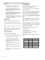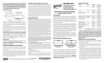
1
MODEL P531, P532 AND P532UI
FLAME MONITOR
OPERATING MANUAL
WORLD LEADER IN FLAME MONITORING
TABLE OF CONTENTS
DESIGN FEATURES OVERVIEW ................. 1
Parity................................................................. 6
Viewing Head Selection.....................................1
20ma output ...................................................... 6
USER INTERFACE OVERVIEW .................... 1
Default (global default) ...................................... 6
Default Settings .................................................2
FLAME RELAY CONTROL ............................ 6
Numerical configuration.....................................2
Flame On, Flame OFF ...................................... 6
Alternate – Primary............................................2
Temperature display ......................................... 6
DEFAULT DISPLAY FOR P532, P532 UI ..... 2
AUTOMATIC SETUP...................................... 6
Flame count.......................................................2
Fit ...................................................................... 6
Lockout..............................................................3
Fit procedure ..................................................... 7
Alternate Indicator .............................................3
Sequence .......................................................... 7
Hot Viewing Head Indication .............................3
Sequence Procedure ........................................ 7
Primary / Alternate selection..............................3
Filter .................................................................. 8
Using the Prim/Alt switch...................................3
P531 AND P532UI .......................................... 8
To reset Modbus Prim/Alt register .....................3
Display for P531................................................ 8
Non-Advanced viewing heads ...........................3
Flame On .......................................................... 8
Replacing viewing heads...................................4
Flame Signal: .................................................... 8
MENU STRUCTURE ...................................... 4
LOCKOUT ........................................................ 8
Viewing Head Set ............................................4
Status................................................................ 9
Viewing head parameters (gains and filters) .....4
P522 MODE .................................................... 9
Channel Set.......................................................4
P522 mode operation........................................ 9
Associate Viewing head with channel ...............4
INFRARED GAIN............................................ 9
FFRT .................................................................5
Gain boundaries................................................ 9
Delay On ...........................................................5
INSTALLATION NOTES............................... 10
Analog out gain .................................................5
Mounting: ........................................................ 10
Alarm Set point..................................................5
Power connection:........................................... 10
Temperature Alarm (Viewing Head) ..................5
Remote 20 mA ............................................... 10
Default (Channel) ..............................................5
Relays ........................................................... 10
Option Menu......................................................5
Flame Relays .................................................. 10
Address .............................................................5
Alarm Relays................................................... 10
Baud ..................................................................5
Viewing head (See Figures 1 and 2) ............... 10
Power Reset......................................................5
Alternative Setting Selection ........................... 10
Panel ................................................................6
P522 Mode ..................................................... 10
TROUBLESHOOTING NOTES ....................10
If the display is blank: ...................................... 10
If only one line is blank: ................................... 10
If the viewing head is not listed. ..................... 11
Channels display LKOUT ................................ 11
The Display flashes “HOT” ............................. 11
CODE display.................................................. 11
MODBUS PROTOCOL .................................12
Legacy Modbus support .................................. 12
Extensions ...................................................... 12
Modbus function support: ............................... 14
CONTACT INFORMATION...........................14
Sales and applications support: ...................... 14
Factory and repairs: ........................................ 14
SPECIFICATIONS ........................................23
Electrical - Model P531 AC, P532 AC ............. 23
Electrical - Model P531 DC, P532 DC............. 23
Outputs............................................................ 23
Inputs .............................................................. 23
Serial Communications ................................... 23
Flame .............................................................. 24
Compatibility.................................................... 24
Fuses .............................................................. 24
Maintenance.................................................... 24
Cleaning .......................................................... 24
Cable............................................................... 24
Environmental ................................................. 24
IRIS MODELS P531, P532 AND P532UI OPERATING MANUAL
DESIGN FEATURES OVERVIEW
The IRIS Models P531and P532 feature a new design
in flame monitoring technology. The dual processor
system is capable of monitoring three viewing heads
simultaneously. It can also monitor both UV and IR
separately from one S55xx viewing head. In addition,
three marginal alarm relays can be configured to provide a secondary indication if the flame count falls below set point or if a viewing head temperature reaches
70° C (158° F).
The P532 and P532UI makes use of three scrolling
dot matrix displays capable of displaying alphanumeric
characters in three different colors as follows:
Red indication for IR
Green indications for UV
Orange indication for mixture of UV and IR
The P531 Signal Processor uses seven discrete
LED’s for display. These include:
Tricolor flame strength flashing indicators for each
channel.
3.
Auto Filter: Used for definitive infrared calibration. The sequence procedure (above) is performed on each of the 8 filter settings. The bestdifferentiated filter is chosen and configured for
gain, flame on and flame off settings.
The P532 provides the use of a lockable front panel
for restricting unauthorized access. The P531 uses the
removable P532UI to achieve this feature.
Both Signal Processors have viewing head error detection with viewing head lockout capabilities. (this
requires user intervention)
A P522 operation mode can be achieved by installing
a jumper between the two P522 pins.
Changing viewing head types (while the system is
operational) will cause the processor to go into lockout
mode. (This is a safety feature).
The P531 and P532 are compatible with RS-422 and
Modbus protocol, and are field upgradeable with firmware download capabilities.
Viewing Head Selection.
Relay and status indicators.
In addition to automatic viewing head detection, each
channel and viewing head can be associated with two
sets of configuration data as follows:
1.
Primary: This is the normal viewing head configuration.
2.
Alternate: This is a set of alternate settings that
can be activated by applying a voltage across
the alternate select pins for each specific channel or writing configuration to Modbus register.
Automatic set up functionality is a feature whereby
each channel can be configured automatically in one
of three ways:
IRIS Models S702 / S802 IR and the S706 / S806 UV
viewing heads can be connected to Viewing Head #3.
Viewing head #3 will default to be assigned to channel “A”.
IRIS Models S552 IR and S556 UV together with the
S550 that utilizes both UV and IR sensors can be connected to Viewing Head #1 and #2.
Viewing Head #1 will default to be assigned to
channel ‘B”.
Viewing Head #2 will default to be assigned to
channel “C”.
Note: Alternate channels default to NONE
USER INTERFACE OVERVIEW
1.
Auto Fit: The flame is monitored and the gain is
adjusted to produce an optimal count of between
1100 and 1300. The flame on will then be set at
800 and flame off will be set to 600.
2.
Auto Sequence: The gain will first be adjusted
as in the Auto Fit routine and then the flame on
and flame off settings will be adjusted. (This
requires turning off the flame).
Page 1
The P532 front panel and the P532UI (User Interface)
makes use of nine push buttons for operation. Each
of these buttons has at least one specific purpose.
All access to the front panel operation is initiated by
pressing and holding a button for two seconds (this
eliminates the possibility of inadvertent access).
In all cases, only the available options will be displayed.
IRIS MODELS P531, P532 AND P532UI OPERATING MANUAL
There are three menu branches:
1.
Channel menu has all configuration items associated with the channel.
Alternate – Primary (during configuration)
The top line will display ALT or PRIM, followed by :
Channel letter (A, B, or C)
2.
Viewing head menu has all configuration items
associated with the Viewing head.
OR
Viewing Head number (1, 2, or 3)
3.
Options menu has global and system configuration items and information.
Note: The RESET button will return you to the default display from any place in the menu structure.
If left for a period of time without intervention, the
display will revert back to the default display.
(Except during auto calibration modes)
A channel (Primary and or Alternate) can be assigned
to a viewing head (or viewing head sensor in the case
of advanced S550x viewing heads).
Default Settings
Default choices are available in two menus.
1.
Channel (Primary and or Alternate) defaults all
parameters under the channel menu except for
the viewing head association. The viewing head
(or the viewing head sensor) assigned to the
defaulted channel will also be defaulted.
2. Options defaults all channels and viewing heads
as well as resetting the system wide parameters
and viewing head to channel association.
Note: The response to YES is always the STORE
button.
Numerical configuration.
Green is the current set point stored in memory.
Orange indicates that the setting has been changed
but not saved yet.
The color of this line (top)
Red indicates that this configuration is active at
present
Green indicates a non active configuration.
The CHANNEL button will toggle between these two
configurations.
Alternate configurations can be activated by applying
a voltage across the select terminals.
DEFAULT DISPLAY FOR P532, P532 UI
The default display will appear most of the time. Each
line on the display will always be associated with the
same channel. The default display will show the flame
count for all 3 channels.
IR saturation is indicated by flame counts of 9999
Flame count
Normal Flame counts are in the range of 0 to 3500 for
the S55x viewing heads and 0 to 3000 for S70x / S80x
viewing heads (viewing head #3)
A red display will indicate that channel is associated
with the IR only portion of a viewing head’s output.
(Saturation is indicated for advanced viewing heads
only)
A green display will indicate that channel is associated with the UV only portion of a viewing head’s output.
The speed of changing numerical values is accelerated as the key is held down.
An orange display will indicate that channel is associated with a mixture of both IR and UV from a S550
viewing head.
The UP and DOWN buttons are used to change numerical values or to jump between configuration parameters.
A Blank Line indicates that no viewing head is associated with the channel.
The SELECT button is used to jump to the next item in
all 3 of the menu structures, or to select intermediate
parameters that will not be stored.
This could also indicate that the gain of an associated
sensor is zero.
Page 2
IRIS MODELS P531, P532 AND P532UI OPERATING MANUAL
A Bar Graph will be displayed in the last digit of the
default display.
The configuration is written to Modbus register
The Primary configuration will be used for operation if:
The graph is proportional to the analog output (20ma)
and is affected by the flame count and the analog gain
for the channel.
Lockout
LKOUT will be displayed on the panel if a viewing
head error has occurred. (Flame relays will trip and
the channels will remain locked out until any button is
pressed on the front panel). Lockout will also occur
when an unexpected viewing head is detected. This
will occur when changing head types or attaching new
viewing heads to a system that has been defaulted.
LKOUT Cannot be cleared by a power reset (to clear
push any button)
Verification of all viewing head and channel parameters is required after a lockout has occurred.
Alternate Indicator
The middle pixel of the rightmost column will be illuminated if the Alternate configuration for that channel is
currently in operation.
Hot Viewing Head Indication
A warning will be displayed for 1 second in each 4
seconds if a viewing head attached to Viewing Head
#1 or Viewing Head #2 terminals exceeds a temperature of 70° C (158° F).
Seeing that the viewing head may not be associated
with any particular channel the number of the offending viewing head will be displayed.
No voltage is present and Modbus is configured for
Primary (default)
To reset Modbus Prim/Alt register
Use the serial RS-422 communications port (see Modbus register map)
Doing a system default (Options / Default) will set this
register to Primary for all channels.
Non-Advanced viewing heads
(S550 models with no following letter designation)
The processor treats non-advanced viewing heads as
a single sensor. The UV and IR cannot be separated
as with the advanced viewing heads.
To configure for UV only the IR gain should be set to
zero, conversely the IR only can be seen if the UV
gain is set to zero (note the appropriate color change
of flame count display).
These two configurations can be saved in primary and
alternate for a single channel and switched when
needed.
Individual sensors of advanced viewing heads (and
non-advanced viewing heads) can be assigned to
channel configurations Primary and Alternate.
A sensor CANNOT be assigned to more than one
channel and a primary and an alternate configuration all at the same time.
Except for this notification, no other action is taken
when a viewing head is hot.
A sensor can be assigned to both Primary and Alternate configurations of the same channel (but not to
another channel)
Primary / Alternate selection
OR
Two sets of configuration data can be stored and used
for each of the 3 channels.
A sensor can be assigned to more than one channel
(all either primary or alternate).
Both the alternate and primary configurations can
be viewed and adjusted from the panel.
All channel parameters settings can be configured for
both Primary and Alternate usage.
Using the Prim/Alt switch.
The color of the words PRIM or ALT in the display
indicates if it is the current configuration in use.
The Alternate configuration is used for operation if:
RED selected.
A voltage is applied across the associated alternate
select pins, OR
Page 3
Green not selected.
IRIS MODELS P531, P532 AND P532UI OPERATING MANUAL
A letter or a number will be displayed after the selection indicating the Channel of Viewing head that is
being configured or viewed.
Letters (A, B, C) indicate Channels
Numbers (1, 2, 3) indicate viewing head numbers
Note: Invalid configurations will not be allowed and
an “IN USE” warning will be displayed if the sensor
is already in use by conflicting configuration. The
offending configuration that is using the sensor
must be configured to either use a different sensor
or use no sensor at all (NONE).
Replacing viewing heads
If a viewing head is replaced with a different type
(model), all channels using the head will lockout.
Only one button press is required to clear all lockouts.
Toggle primary and alternate viewing head parameters using the CHANNEL button.
The appropriate configuration can be selected with the
SELECT button.
Display of (PRIM/ALT) in Red indicates that the
displayed parameter is being used by the channel
selection (for the control of the channel relays).
Viewing head parameters (gains and filters)
The valid parameters for the viewing head can be
scrolled through using the SELECT button. The current stored setting will be displayed in green.
To adjust the gains and filters the UP and Down buttons will be used.
The STORE button must be pressed to store the appropriate setting.
If more than one channel or Alternate/Primary configuration was using the head then the channel assignments will be set to none.
Channel Set
Advanced viewing heads will be assigned to Primary
for one of the previously used channels only.
Scroll between channels “A”, “B”, and “C”, using the
UP, DOWN, or CHANNEL SET buttons.
All viewing head gains and filters will be set to default
values.
Select the Channel to view or configure with the SELECT button. The viewing head associated with the
channel will now be displayed.
Both Primary and Alternate settings will be defaulted.
Note: Changing viewing heads (to that of the same
Model) while the unit is operating may cause a lockout. (Cleared with a press of a button).
MENU STRUCTURE
Three menus are accessible from the front panel.
Pressing and holding the appropriate button for 2 seconds will open the menu.
Viewing Head Set
Viewing head selection : (See Flow Chart 1)
Channel selection: (See Flow Chart 2)
The top line of the display will indicate either PRIM or
ALT along with the channel letter. Toggle between
these using the CHANNEL button.
Scroll through the channel menu items using the SELECT button.
Associate Viewing head with channel
Associating a viewing head with the channel can be
done by scrolling through the viewing heads using the
UP and DOWN buttons. Then select the viewing head
with the STORE button.
If an advanced viewing head is selected with the
STORE button from the channel Viewing head selection menu, then another menu choice will appear
IR UV.
All attached viewing heads can be scrolled through
using the UP and DOWN or the VIEWING HEAD SET
buttons.
The viewing head to be accessed can be selected with
the SELECT button.
The top line of the display will indicate either PRIM or
ALT along with the viewing head number.
Using the UP or DOWN buttons scroll among
1.
Both IR and UV will be mixed for this channel
2.
IR? - Only IR will be used for this channel
Page 4
IRIS MODELS P531, P532 AND P532UI OPERATING MANUAL
3.
UV - Only UV will be used for this channel
Temperature Alarm (Viewing Head)
The appropriate choice must be stored with the
STORE button.
The Alarm relays can be configured to energize if a
viewing head with a temperature sensor gets hot (70°
C (158° F) or above).
If association is invalid (the sensor is associated with
another channel and Alt) “IN USE” will be displayed.
The channel that is using the sensor must be disassociated, either by selecting another sensor for that
channel or setting it’s sensor association to NONE.
Set both Primary and Alternate Alarm set points to
ZERO
Channel A alarm is for Viewing head #1
Channel B alarm is for Viewing head #2
FFRT
Viewing head #3 has no temperature feature.
Using the UP and DOWN buttons then STORE the
Flame Failure Response time.
To set both Alarm set points for one channel first set
one of the set points to zero then press CHANNEL
button to access the other. (note the change in the top
line of the display).
FFRT
Nominal Opening
Maximum FFRT
1
1 sec
2 sec
Default (Channel)
2
2 sec
3 sec
To reset the channel to default values:
3
3 sec
4 sec
Delay On
Scroll to YES using the UP or DOWN buttons and
then press the STORE button. The STORE button
must be pressed again to answer the “are you sure?”
question.
Using UP and DOWN button and STORE the Delay
relay on time.
Option Menu
Analog out gain
System wide configuration parameters
Selecting this parameter (with either the UP or DOWN
button) will cause the display to change.
(See Flowchart 3)
The Gain (0 – 100) will be displayed on the line associated with the channel being adjusted in the color
associated with the flame count. There will be a bar
graph that is proportional to the analog (20ma) output
for that channel. (Selected channel only.)
Adjusting the gain using the UP and DOWN buttons
will (in real time) produce outputs on the analog output
pins and on the bar graph proportional to the current
flame count.
Real time bar graph display of the analog gain setting will be calculated from the fame count of the
channel selection
Alarm Set point
Using the UP and DOWN buttons then STORE the
Alarm set point.
The alarm relay can be disabled by setting this parameter to zero.
Page 5
Address
Using the UP and DOWN buttons, enter the value for
the RS-422 node address. (Default is zero)
The P532 will not respond to the Zero “Broadcast”
address.
Baud
Using the UP and DOWN buttons, toggle between
baud rates for the RS-422 press then STORE to accept. (Default is 9600)
Power Reset
To reset the power:
Scroll to YES using the UP or DOWN buttons and
then press the STORE button. The STORE button
must be pressed again to answer the “are you sure?”
question. This cycles power to all the viewing heads
and restarts both processors.
IRIS MODELS P531, P532 AND P532UI OPERATING MANUAL
Panel
The front panel can be disabled for configuration
changes by entering a LOCK CODE. The lock code is
available from Iris Systems.
If panel is locked: All parameters are viewable but
none can be changed.
Parity
Using the UP and DOWN buttons, toggle between
parities for the RS-422 press then STORE to accept.
(Default is none)
20ma output
Using the UP and DOWN buttons, toggle between the
0 to 20 ma output or the 4 to 20 ma output then
STORE to accept. (Default is 4 to 20).
Default (global default)
To reset the system to default values:
Scroll to YES using the UP or DOWN buttons and
then press the STORE button. The STORE button
must be pressed again to answer the “are you sure?”
question.
All channels will be associated with the default viewing
heads, all channel set points will be defaulted, and all
viewing head parameters will be set to default values
(both Primary and Alternate). Channels will be set to 4
– 20 ma output mode.
FLAME RELAY CONTROL
The main flame relays are controlled by the Flame On
and Flame Off settings. The relays are energized
once the flame count has exceeded the Flame On
setting for Delay ON consecutive seconds. Conversely the relays are de-energized once the flame
count has been less than Flame Off setting for FFRT
consecutive seconds. (See flowchart 4)
Flame On, Flame OFF
Hold either of these buttons for 2 seconds to enter the
relay menu.
Push the SELECT button at any time to change to the
next available channel.
Pushing the CHANNEL button will toggle between ALT
and PRIM settings (red display of Prim/Alt will indicate
parameter is currently active)
Pushing either the FLAME ON or FLAME OFF will
display the current set value in green.
Use the UP and DOWN buttons to change the settings
of these parameters and STORE to save the values.
Temperature display
See Configuration control charts 1 and 2
The temperature of a supported viewing head will be
displayed when the TEMP button is held for 2 seconds. This display will also show the model of the
viewing head.
Certain versions of the S550 were produced without a
temperature sensor. These will display zero for temperature.
AUTOMATIC SETUP
The flame monitor can be configured automatically in
two different ways. Seeing that this configuration is for
a specific channel it therefore falls under the channel
menu.
Only a currently selected channel can be set up
automatically, as indicated by a red Prim/Alt display
Fit
The auto fit menu is entered by selecting AUTOMATIC
from the channel menu.
The auto fit configuration only affects the gain of the
specific sensor selected and Flame On and Flame Off
set points).
A channel utilizing 2 simultaneous sensors (S550)
cannot be calibrated with this procedure.
It is necessary to have a flame present to use auto
set.
The gain will be set so that the flame count for the
specific sensor is between 1100 and 1300. The Flame
On will be set to 800 and Flame Off to 600.
If this is unobtainable, a message will be displayed
indicating the flame is too high or too low. (High flame
requires the installation of an orifice).
Note: If a channel is using two sensors a choice will
be given to turn one or the other of these sensors
off. The corresponding gain will be set to Zero for
S550 viewing heads or the sensor will be selected
for the specific channel for advanced viewing heads
Page 6
IRIS MODELS P531, P532 AND P532UI OPERATING MANUAL
Fit procedure
1.
2.
3.
Using the channel menu procedure (above) select the AUTOMATIC menu branch by toggling
to yes using the UP or DOWN buttons and press
STORE.
If prompted to turn off a sensor, use the UP or
DOWN button to display the sensor that is to be
turned off then press SELECT to turn it off.
If prompted to UNCAL a channel (see note
above), press the STORE button to answer the
YES? Query to acknowledge the side effect this
will have on the other channel.
4.
Using the UP or DOWN buttons, scroll to FIT
and press SELECT to select the automatic fit
procedure.
5.
If TURN FLAME ON is displayed (the flame relay is not energized) turn the flame on. Calibration will not continue without the flame relay being energized.
Note: Calibration cannot be done with the flame
relay off. Prior to entering the Automatic menu sufficient flame/gain combination must be available to
ensure the flame relay will be energized.
A rejected gain calibration can occur if fluctuations
of signals are detected during calibration or if the
signal is such that the gain cannot be determined
automatically.
Note: In certain cases acceptable results may be
obtained by manually setting the gain to the processors best guess and then re running the procedure.
Sequence
Auto Sequence configures the gain and relay set
points for a specific channel.
When entering the auto sequence configuration, the
auto fit procedure (above) will be automatically performed first.
Once the proper gain setting has been established,
the system will take samples of the flame to eliminate
flicker error.
Flame on will be sampled for 60 seconds and flame off
(dark) will be sampled for 60 seconds.
Flame sample times can be shortened by pressing
a button. However, a minimum of 10 seconds is
required. If the RESET button is held for 1 second
the procedure will abort.
Sequence Procedure
1.
Using the channel menu procedure above, select the AUTOMATIC menu branch by toggling
to yes using the UP or DOWN buttons and press
STORE.
6.
Fit calibration will take less than 17 seconds. A
countdown timer will display the maximum remaining seconds.
7.
Completion of Fit calibration will display:
2.
AUTO FIT OK! Completion of successful gain calibration. New gain parameters are stored and the
display will revert to default display.
Using the procedure outlined in Fit Procedure
above, follow all steps except SELECT SEQUENCE from step 4 above.
3.
Once the Fit portion of the Sequence calibration
has been successfully completed:
4.
START BURN YES? Question will be asked,
press the STORE button to start the 60-second
count down for the flame on (bright) portion of
the calibration.
5.
Flame samples times can be shortened by
pressing a button for 1 second. However, a minimum of 10 seconds is required.
LOW FLAME SIGNAL Insufficient flame signal to
allow for optimal flame count output. Install orifice
with larger hole. Original calibration will be restored.
HIGH FLAME SIGNAL flame signal too strong to
allow for optimal flame count output. Install orifice
with smaller hole. Original calibration will be restored.
GAIN REJECTED Number. If the unit cannot attain
appropriate gain calibration within the time allotted
“REJECTED” will be displayed along with the type
of gain being adjusted and the processors best
guess for gain calibration.
Page 7
IRIS MODELS P531, P532 AND P532UI OPERATING MANUAL
6.
A countdown clock will be displayed on the bottom line indicating the remaining time in seconds.
7.
After the completion of the bright time period a
TURN FLAME OFF command will be displayed
followed shortly with the FLAME OFF? Question.
8.
The Flame must now be turned off.
9.
Once the flame is off, pressing the STORE button to start the dark period counter. (Dark sample times can be shortened by pressing a button
for one second. However, a minimum of 10 seconds are required.)
10. After completion of the dark sequence portion,
an evaluation will take place and a prompt will
appear.
If the setting parameters are outside of reasonable
bounds, the sequence will be rejected (SEQUENCE
REJECTED). The problem should be corrected before another sequence is attempted.
A successful sequence is indicated by all green
display.
A marginal sequence is indicated by an orange
display.
Top line will display Flame On set point.
Second line will display Flame Off set point
Third line will display the channel that was adjusted. In the case of a marginal sequence, a YES
prompt will have to be answered with the STORE
11. If the Sequence is rejected, either automatically
or by the user, the original settings will be restored.
Filter
The Gain will be readjusted at each filter setting and
the flame will be sampled for 20 seconds at each
level.
This calibration will take about 8 minutes
Flame on will be sampled for 20 seconds and flame off
(dark) will be sampled for 20 seconds.
Flame sample times cannot be shortened in the
auto Filter procedure. The filter can be aborted by
holding the reset button for one second.
P531 AND P532UI
Setup and operation of the P531 is the same as for
the P532 when using the P532UI
The P532 UI can be connected to and disconnected
from the P531 during operation for monitoring and
configuration. Other methods of monitoring and configuration include Modbus devices (either through the
RS-422 port or the RS-232 port).
Display for P531
The 7 LED’s on the P531 will provide information
about status and flame signals for all channels.
Flame On
The display has software indication that the Flame
relay is energized
Note: as with the P532 this is not a hardware LED
Flame Signal:
Indication of the flame strength flashes
From one flash every few seconds to rapid flash
The color indicates signal configuration: (channel configured for: )
Red indicates IR only
Green indicates UV only
Auto Filter configures the gain and relay set points for
a specific infrared channel
When entering the auto Filter configuration, the auto fit
procedure (above) will be automatically performed
first.
IF proper gain setting can be established, the system
automatically runs a shortened version of the Sequence (above) configuration on all 8 filter levels.
Orange indicates the channel is configured to detect
both UV and IR
LOCKOUT
Red Green Red Green ….. Flashes once a second.
The Flame On indicator will be out.
Push the reset button to clear lockouts. (This is the
only way to clear a LOCKOUT)
Page 8
IRIS MODELS P531, P532 AND P532UI OPERATING MANUAL
Status
INFRARED GAIN
A Green heartbeat (one quick green flash each second) indicates system normal (self check)
Analysis of the Electrical and Digital (Software)
gains for the S55xx Viewing Heads.
A Red / Green heartbeat (alternating color one
quick flash each second) indicates one or more
viewing heads are Hot (70 deg C or more). Other
system functions are normal.
The Sx55x viewing heads that are IR equipped have a
two stage gain system.
A Red Inverted heartbeat (Red light with one quick
flash dark each second): The display processor is
not receiving data from signal processor. (Interprocessor communications error.)
A solid color light or no light or any other flash pattern indicates a system failure. No LED’s illuminated
could also indicate a power loss.
P522 MODE
The P532 can be made to behave like the P522
Connect a jumper between ground and the P522 pin.
The unit will revert to P522 the next time it is powered
up.
There is a 7 step electrical “analog” gain that is used
external to the processor to amplify the signal before it
enters the processor. Indicated by the left digit.
Once the signal is at the processor, a “digital” software
gain can then be applied. Indicated by the last two
digits.
These gain adjustments may not be transparent to the
user as a slight amount of non-linearity may occur
when changing from one electrical gain setting to another.
During setting a hysteresis is built in to keep small
changes in the digital range. If an analog gain boundary is crossed, a finer adjustment can be achieved by
going back in the other direction.
There is no support for viewing head #3 in this mode.
NOTE: If the jumper is installed or removed and the
power is reset then the entire system will revert
back to default settings.
P522 mode operation
Note: illegal values for gain between x00 and x37
(except for low range).
Gain boundaries
The following table is a list of boundaries, for
changing the electrical gain.
Channel Viewing Head assignments:
Channel A Only will be operational (both Prim or Alt)
IR gain settings transitions for the S55xx viewing
heads.
P 522 will be displayed on the second line
Only channel A Flame relays will operate
If power is applied across Alternate 1 pins, the
channel will revert to the Channel A Alternate configuration parameters.
The bottom line will display the active selection.
From
To
Electrical gain
0
99
1
138
199
2
238
299
4
338
399
8
The channel A marginal alarm will function independently.
438
499
16
538
599
32
The alarm can be disabled by setting the trip point
to zero.
638
699
64
Separation of UV and IR is supported for advanced
viewing heads.
Page 9
IRIS MODELS P531, P532 AND P532UI OPERATING MANUAL
INSTALLATION NOTES
Viewing head (See Figures 1 and 2)
Mounting:
Viewing heads are connected to the appropriate terminals using the compatibility list.
The P531 or P532 Signal processor should be mounted
(using the 4 holes in the corners of the base) to a vertical surface in a location with free air circulation on
the top, bottom and sides.
Source Impedance Resistors 470 Ohm ¼ Watt must
be installed between SC and SGND for all cable runs
to S55x viewing heads between 300 and 700 ft.
Power connection:
Alternative Setting Selection
DC units should be connected to a stable 24-volt DC
supply.
For each of the 3 viewing heads:
AC units should be connected to an AC mains supply
Connect +Sel and ground through a switch from a DC
supply for selecting alternate viewing head settings.
Battery backup can be connected to the +24 BATT
terminal.
The +24v OUT terminal can be used to supply power
for this purpose (on AC units).
To prevent discharging the battery, its voltage must
be less than the main supply (for DC units) or less
than 24 volts (for AC units). This can be adjusted
using series silicon diodes to provide a voltage drop
of 0.7 volts each.
P522 Mode
To Use the P532 in Reduced Feature mode install a
jumper between the P522 mode terminal and ground.
Remote 20 mA
Then power must then be cycled.
Current meters can be connected to the remote meter
outputs with the RET as a common return.
WARNING: Do NOT connect P522 mode terminal
to a power source.
Relays
(See Figures 4 and 5)
Self-check contacts are provided for both normally
open and normally closed positions.
Connect the Self-check actuator to whichever of these
terminals is required.
The Self-check relay is internally interlocked with the
flame relays so that whenever the Self-check relay
opens all of the flame relays will open as well.
TROUBLESHOOTING NOTES
If the display is blank:
Unplug all viewing heads (should display “NO VH#
DETECTED”).
If display still blank then:
Hold the Reset button for 2 seconds:
If address is displayed then reset factory defaults:
Else return unit to factory for service.
Flame Relays
If only one line is blank:
Each of the flame relays provides 2 sets of normally
open and normally closed positions.
Connect the Burner supply to the required flame terminals.
Alarm Relays
Alarm contact is a normally open contact that will provide a connection to it’s RET when the flame count
falls below the set point. Or (if configured) the viewing
head temperature exceeds 70° C (158° F). Connect
the Alarm actuator to these terminals.
Check that the channel is associated with an operational viewing head.
Push channel until the channel letter is displayed
then push select.
Scroll through viewing heads and store the one required.
If the Channel is associated with a viewing head,
check that the viewing head’s gain is not set at zero.
Page 10
IRIS MODELS P531, P532 AND P532UI OPERATING MANUAL
If the viewing head is not listed.
If the viewing head is not listed as a choice in either
the Viewing head or the channel branch:
Check that the viewing head is compatible with the
P531/P532.
Check that the viewing head cable is in good condition.
Verify that 24 volts DC is present at the cable head.
Note: power to VH #3 is pulsed when no viewing
head has answered. Check that the viewing head is
operational.
A meter or Oscilloscope on the SC with reference to
ground will show:
At least 20% duty cycle at 15 volts Peak for
S55x viewing heads.
At least 10% duty cycle at 24 volts Peak for
S70x/S80x viewing heads.
With S70x and S80x viewing heads the Green LED
will flash once per second.
S55xx viewing heads will show a number on the
display.
Viewing heads without numeric displays will flash if
flame signal is present.
Substitute a known good viewing head using a
known good cable.
Channels display LKOUT
Channels display LKOUT that will not stay cleared
(after pressing any key).
Viewing head problem or cable problem. See above
steps. (Reset OPTION defaults).
The Display flashes “HOT”
Indicates that the viewing head listed is nearing or
exceeded maximum operational temperature. The
system will try to continue operating as long as it can
and the flashing display is only a warning.
CODE display.
This is an indication of a processor failure.
It can be caused by a power failure during a memory
store operation or other more serious fault.
Page 11
If the unit is not restored by cycling the power and setting factory defaults:
Record the numbers on the display.
Remove the unit from service and return it to
the factory for failure analysis and repair.
IRIS MODELS P531, P532 AND P532UI OPERATING MANUAL
MODBUS PROTOCOL
Legacy Modbus support
* 40001 Flame Count (active channel in 522 mode) other wise
ZERO
* 40002 Processor Status R/O
0x or Discrete
* 000001 viewing head channel selected 0=Chan A (same pin
4 VH1 gain select)
* 000002 flame on relay status (not used for P532) (reads
zero)
* 000003 Processor Lockout status 0 = lockout (any channel
locked out)
* 000004 Panel access disabled 0 = disabled
* 000005 4 - 20 ma output 0 = 0 to 20 ma output
Primary
* 40003 Flame On Channel A (0 -> 2999)
* 40004 Flame On Channel B (0 -> 2999)
* 40005 Flame Off Channel A (0 -> 2999)
* 40006 Flame Off Channel B (0 -> 2999)
* 40007 Gain Channel A 20ma Gain Primary (0 -> 99)(0 – 100
for P532)
* 40008 Gain Channel B 20ma Gain Primary(0 -> 99) (0 – 100
for P532)
* 40009 IR Analog Gain VH 1 (portion of total IR gain) (R/O
P532)
* 40010 IR Digital Gain VH 1 (portion of total IR gain) (R/O
P532)
* 40011 IR Filter VH 1 (unsigned char) (1 -> 8)
* 40012 UV Gain VH 1(unsigned char) (0 -> 99)
* 40013 IR Analog Gain VH 2 (portion of total IR gain) (R/O
P532)
* 40014 IR Digital Gain VH 2 (portion of total IR gain) (R/O
P532)
* 40015 IR Filter VH 2 ( 1 -> 8)
* 40016 UV Gain VH 2 ( 0 -> 99 )
* 40017 Viewing head type Viewing head #1 R/O
* 40018 Viewing head type Viewing head #2 R/O
* 40019 Temperature Channel A R/O
* 40020 Temperature Channel B R/O
* 40021 Time Delay (upper nibble Ch B) Lower nibble channel A
(Read change Write)
* 40022 FFRT (upper nibble Ch B) Lower nibble channel A
(Read change Write)
* 40023 Software Versions R/O
* 40024 Model number P522 version 5.2 and earlier will read 0
P522 version 5.3 and later will read 520
Alternate viewing head #1
* 40038 IR Gain VH 1
* 40039 IR Filter VH 1
* 40040 UV Gain VH 1
Alternate viewing head #2
* 40041 IR Gain VH 2
* 40042 IR Filter VH 2
* 40043 UV Gain VH 2
Alternate viewing head #3
* 40044 IR Gain VH 3
* 40045 UV Gain VH 3
Alarm set points Primary
* 40046 Alarm set point Channel A (0 -> 2999)
* 40047 Alarm set point Channel B (0 -> 2999)
* 40048 Alarm set point Channel C (0 -> 2999)
Advanced viewing head flame counts for S550A
and later
*40049 Viewing head #1 IR component
*40050 Viewing head #1 UV component
*40051 Viewing head #2 IR component
*40052 Viewing head #2 UV component
*40053
Channel "A" R/O
* 000001 bit 0 flame relay status
* 000002 bit 1 alarm relay status
* 000003 bit 2 channel Autoset (Primary or Alternate)
* 000004 bit 3 channel lockout (Primary or Alternate)
* 000005 bit 4 Primary active = 1 Alternate active = 0
* 000006
* 000007
* 000008
*40054
Channel "B" R/O
* 000001 bit 0 flame relay status
* 000002 bit 1 alarm relay status
* 000003 bit 2 channel Autoset (Primary or Alternate)
* 000004 bit 3 channel lockout (Primary or Alternate)
* 000005 bit 4 Primary active = 1 Alternate active = 0
* 000006
* 000007
* 000008
Extensions
(for P531/P532 (RS-422) to the Modbus protocol)
*40055
Channel "C" R/O
* 40024 Model R/O P532 will read 532
* 40025 Flame Count channel A (R/O)
* 40026 Flame Count Channel B (R/O)
* 40027 Flame Count Channel C (R/O)
* 40028 Flame On Channel C Primary
* 40029 Flame Off Channel C Primary
* 40030 Gain Channel C 20ma Gain Primary (0 -> 100)
* 40031 IR gain VH 3 (1 to 9) Primary
* 40032 UV Gain VH 3 (Total UV gain for P532) (unsigned char)
(1 -> 9) Primary
* 40033 Viewing head #3 type R/O
* 40034 Time Delay Channel C Primary
* 40035 FFRT Lower nibble channel C Primary
* 40036 IR Gain Viewing Head #1 (primary) (equivalent to
40009 and 40010)
* 40037 IR Gain Viewing Head #2 (primary) (equivalent to
40013 and 40014)
* 000001 bit 0 flame relay status
* 000002 bit 1 alarm relay status
* 000003 bit 2 channel Autoset (Primary or Alternate)
* 000004 bit 3 channel lockout (Primary or Alternate)
* 000005 bit 4 Primary active = 1 Alternate active = 0
* 000006 bit 5
* 000007 bit 6
* 000008 bit 7
Page 12
IRIS MODELS P531, P532 AND P532UI OPERATING MANUAL
*40069
*40056
Channel "A” Primary Read/Write
Channel "A” Alternate Read/Write
* 000001 bit 0
* 000002 bit 1
* 000003 bit 2
* 000004 bit 3
* 000005 bit 4 (bit 4 and 5 are viewing head attached
to channel)
* 000006 bit 5 0 ,0 = no viewing head 0,1 = vh #1
….etc.
* 000007 bit 6 IR // for Advanced viewing heads
* 000008 bit 7 UV // for Advanced viewing heads
* 000001 bit 0
* 000002 bit 1
* 000003 bit 2
* 000004 bit 3
* 000005 bit 4 (bit 4 and 5 are viewing head attached
to channel)
* 000006 bit 5 0 ,0 = no viewing head 0,1 = vh #1
….etc.
* 000007 bit 6 IR // for Advanced heads
* 000008 bit 7 UV // for Advanced heads
*40070
*40057
Channel "B” Primary Read/Write
Channel "B” Alternate Read/Write
* 000001 bit 0
* 000002 bit 1
* 000003 bit 2
* 000004 bit 3
* 000005 bit 4 (bit 4 and 5 are viewing head attached
to channel)
* 000006 bit 5 0 ,0 = no viewing head 0,1 = vh #1
….etc.
* 000007 bit 6 IR // for Advanced viewing heads
* 000008 bit 7 UV // for Advanced viewing heads
* 000001 bit 0
* 000002 bit 1
* 000003 bit 2
* 000004 bit 3
* 000005 bit 4 (bit 4 and 5 are viewing head attached
to channel)
* 000006 bit 5 0 ,0 = no viewing head 0,1 = vh #1
….etc.
* 000007 bit 6 IR // for Advanced heads
* 000008 bit 7 UV // for Advanced heads
*40071
*40058
Channel "C" Primary Read/Write
Channel "C" Alternate Read/Write
* 000001 bit 0
* 000002 bit 1
* 000003 bit 2
* 000004 bit 3
* 000005 bit 4 (bit 4 and 5 are viewing head attached
to channel)
* 000006 bit 5 0 ,0 = no viewing head 0,1 = vh #1
….etc.
* 000007 bit 6 IR // for Advanced viewing heads
* 000008 bit 7 UV // for Advanced viewing heads
* 000001 bit 0
* 000002 bit 1
* 000003 bit 2
* 000004 bit 3
* 000005 bit 4 (bit 4 and 5 are viewing head attached
to channel)
* 000006 bit 5 0 ,0 = no viewing head 0,1 = vh #1
….etc.
* 000007 bit 6 IR // for Advanced viewing heads
* 000008 bit 7 UV // for Advanced viewing heads
*40059
Pin status R/O
* 000001
* 000002
* 000003
* 000004 bit 3 522 mode pin
PORTC.3
* 000005 bit 4 Channel A Primary = 1 Alt = 0
PORTC.4 (same as 400002 00001)
* 000006 bit 5 Channel B Primary = 1 Alt = 0
PORTC.5
* 000007 bit 6 Channel B Primary = 1 Alt = 0
PORTC.6
* 000008
*40060 SERIAL Number R/O
*40061 ID number READ and WRITE (Signed Integer)
*40062 Operational time each unit = 2 hours of continuous
power on time (R/O)
*40063 Flame On Channel A alternate (0 -> 2999)
*40064 Flame On Channel B alternate (0 -> 2999)
*40065 Flame On Channel C alternate (0 -> 2999)
*40066 Flame Off Channel A alternate (0 -> 2999)
*40067 Flame Off Channel B alternate (0 -> 2999)
*40068 Flame Off Channel C alternate (0 -> 2999)
Page 13
*40072 Gain Channel A 20ma Gain Alternate (0 – 100 )
*40073 Gain Channel B 20ma Gain Alternate (0 – 100 )
*40074 Gain Channel C 20ma Gain Alternate (0 – 100 )
Alarm set points Alternate
*40075 Alarm set point Channel A (0 -> 2999)
*40076 Alarm set point Channel B (0 -> 2999)
*40077 Alarm set point Channel C (0 -> 2999)
Alarm set points Alternate
*40078 Time Delay (upper nibble Ch B) Lower nibble channel A
(Read change Write)
*40079 FFRT (upper nibble Ch B) Lower nibble channel A(Read
change Write)
*40080 Reserved (do not write to this location) reads zero.
*40081 Time Delay Channel C Alternate
*40082 FFRT Channel C Alternate
*40083
Alternate / Primary Switch register Read/(Write
RS-422 only)
* 000001
* 000002
* 000003
* 000004
* 000005 bit 4 Channel A Primary = 1 Alt = 0
* 000006 bit 5 Channel B Primary = 1 Alt = 0
* 000007 bit 6 Channel B Primary = 1 Alt = 0
* 000008
IRIS MODELS P531, P532 AND P532UI OPERATING MANUAL
To reset factory defaults for P531 front port write 30064 (RS232)
*40084 Error code RS422 port only (P531 front port is undefined)
CONTACT INFORMATION
For further information contact:
Sales and applications support:
P531 front panel access only (RS232)
*40085 Baud for the RS422 port
*40086 Parity for the RS 422 port
*40087 Modbus Address for the RS 422 port
IRIS SYSTEMS INC.
7583 Vantage Place
Delta, BC, Canada V4G 1A6
Modbus function support:
* 03 Holding Register Read
* 06 Preset Single Holding Register
* 16 Preset Multiple (Maximum 5 consecutive locations per
message)
Note: If writing multiple presets a failure message
may occur if one of the presets does not fall within
parameters. Presets before the invalid data will be
written correctly to the register. All parameters after
invalid parameter are ignored and an “Illegal data
value” message is returned.
Ph. 800-667-IRIS, FAX 604-581-9790
email: [email protected]
Web: www.iris-systems.com
Factory and repairs:
IRIS SYSTEMS INC.
(JB Systems, Inc.)
4944 113th Avenue N
Clearwater, FL 33760
Ph. 727-545-3900, FAX 727-547-9589
Page 14
IRIS MODELS P531, P532 AND P532UI OPERATING MANUAL
Channel
VH#
Sensor
Flame
ON
Flame
OFF
FFRT
Time
Delay
Analog
Gain
Alarm
A Prim.
A Alt.
B Prim.
B Alt.
C Prim.
C Alt.
TABLE 1: Temperature Configuration Control Chart 1
IR Gain
IR Filter
UV Gain
VH#1 Prim.
VH#1 Alt.
VH#2 Prim.
VH#2 Alt.
VH#3 Prim.
N/A
VH#3 Alt
N/A
TABLE 2: Temperature Configuration Control Chart 2
Page 15
Channel Association
IRIS MODELS P531, P532 AND P532UI OPERATING MANUAL
FIGURE 1: Wiring and connections S55xx Viewing Head
FIGURE 2: Model 700 and 800 viewing head cable connections
Page 16
IRIS MODELS P531, P532 AND P532UI OPERATING MANUAL
MODULAR
CONN.
SCHEM
LABEL
COLOR
TYPE A
COLOR
TYPE B
INTERFACE
LABEL
DESCRIPTION
POWER
SUPPLY
1
NC
WHI
BLU
NC
NC
-
2
TX-
BLK
YEL
RD (A)
FROM
PROCESSOR
-
3
TX+
RED
GRN
RD (B)
FROM
PROCESSOR
-
4
RX-
GRN
RED
TD (A)
TO
PROCESSOR
-
5
RX+
YEL
BLK
TD (B)
TO
PROCESSOR
-
6
GND
BLU
WHI
GND
GROUND
GND
+12VDC
POWER
+12VDC
CAUTION: The order of the colors in the cable can be TYPE A or TYPE B. Check colors at the connector.
FIGURE 3: Wiring of RS-422 to RS-232 Converter to processor
Page 17
IRIS MODELS P531, P532 AND P532UI OPERATING MANUAL
FIGURE 4: P532 DC Wiring Diagram
Page 18
IRIS MODELS P531, P532 AND P532UI OPERATING MANUAL
FIGURE 5: P532 AC Wiring Diagram
Page 19
4.56"
TYP
CHANNEL
SET
VIEW HEAD
SET
FLAME
OFF
STORE
P532 FRONT VIEW
FLAME MONITOR
#2 V.H.
TEMP
RESET
OPTIONS
SELECT
FLAME
ON
#1 V.H.
TEMP
PRESS BUTTONS 2 SECONDS TO ACTUATE
MODEL 532
4.19" TYP
P532
TOP VIEW
4.25" TYP
FLAME
ON
USER INTERFACE
FLAME
SIGNAL
RESET
P531 FRONT VIEW
STATUS
CHAN C
CHAN B
CHAN A
P531
FLAME MONITOR
P531
TOP VIEW
P532UI
TOP VIEW
P531
TOP
VIEW
VIEW HEAD
SET
CHANNEL
SET
SELECT
RESET
OPTIONS
#2 V.H.
TEMP
#1 V.H.
TEMP
P532UI FRONT VIEW
FLAME MONITOR
STORE
FLAME
OFF
FLAME
ON
PRESS BUTTONS 2 SECONDS TO ACTUATE
MODEL 532UI
1.63"
5.80"
TYP
IRIS MODELS P531, P532 AND P532UI OPERATING MANUAL
FIGURE 6: P531, P532, P532UI Dimensions
Page 20
IRIS MODELS P531, P532 AND P532UI OPERATING MANUAL
Viewing Head Setup
Channel
(Prim/Alt)
Viewing Head Selected
“1, 2 or 3”
Select
IR Gain
UV Gain
IR Filter
#2 Temp
#1 Temp
STORE
------
FLOWCHART 1: Viewing Head Set, Channel Set and Option
CHAN SET
#1 Temp.
Select
VH Sell
FFRT
Delay On
Analog out
Alarm
Channel
Prim/Alt
#2 Temp
#1 Temp
STORE
------
FLOWCHART 2: Channel Set
Page 21
Default
Auto
IRIS MODELS P531, P532 AND P532UI OPERATING MANUAL
Options
Select
Address
Baud
#2 Temp
#1 Temp
Power Reset
Panel
Parity
0-20
4-20
Default
#1 Temp
#1 Temp
#2 Temp
STORE
-----STORE
------
#1 Temp
#1 Temp
STORE
------
STORE
-----STORE
------
Reset Heads
And
Processor
Reset
System
Defaults
Enter Code
Lock/Unlock
Routine
FLOWCHART 3: Option Menu - System wide configuration parameters
Select
(Channel)
Flame On
Flame Off
#2 Temp
#1 Temp
Channel
(Prim/Alt)
STORE
------
FLOWCHART 4: Flame On / Flame Off
Page 22
IRIS MODELS P531, P532 AND P532UI OPERATING MANUAL
SPECIFICATIONS
Models P531, P532 and P532 UI
Electrical - Model P531 AC, P532 AC
Primary Input Power
85 – 264 VAC, 47-63 Hz
Battery Backup Voltage
24 VDC (voltage above 24 volt will be the power source)
Electrical - Model P531 DC, P532 DC
Primary Input Power
24 VDC
Battery Backup Voltage
24 VDC (power source is taken from the highest voltage)
Power
(DC unit tested at 100 ms sampling time)
13.2 Watts max. Average (including 3 viewing heads)
16.2 Watts max. Peak (including 3 heads in normal operation)
Outputs
Flame Relay
3 channels of 2 Form C Contacts (DPDT)
Self-Check Relay
1 channel of 1 Form C Contact (SPDT)
Contact Rating
5A at 32 VDC and at 250 VAC
Alarm Relays
3 channels of 1 Form A Contact (SPST-N.O.)
Contact Rating
2 A at maximum 250 VDC or 230 VAC
Analog Flame Signal
0 – 20 mA or 4 – 20 mA 1000 ohm maximum resistance
Power To Viewing heads
100 mA (maximum average)
24 VDC (rated)
Current limited to 200 mA
24v output
24-volt output 50 mA
For Instrumentation use only
Provided for use with Isolated Select inputs
Isolated Select
7.5 – 30 VDC
Input Resistance 3900 ohm
Aux Mode
Connect to ground only (WARNING: do not apply Power)
Sources 1 mA at 5 VDC
Viewing head Signal (for 55x and 70x)
26-Volt P-P Maximum, 1 MA
Inputs
Serial Communications
RS-422 / 4 wire (two twisted pair)
Page 23
Baud
38400, 19200, 9600 or 4800
Parity
None, Even or Odd
Protocol
Modbus (RTU)
IRIS MODELS P531, P532 AND P532UI OPERATING MANUAL
RS-232 (P531 front panel port only)
Baud
Parity
Protocol
19200
None
Modbus(RTU) fixed address of 64
Maximum flame detector response time
5 second
Minimum flame detector self-checking rate
1 second
Maximum flame failure “lock-out” time
2 to 4 seconds (adjustable)
Maximum flame failure response time
2 to 4 seconds (adjustable)
Signal for presence of flame
Flame on set point (adjustable)
Signal for absence of flame
Flame off set point (adjustable)
Flame
No large Maximum flame signal will cause lost flame indication.
Compatibility
Viewing head #3
S702, S706, S802 or S806 (and -PH and –HF versions)
Viewing head #1 or #2
S550x, S552x, S556x (and –PF versions)
Fuses
No user serviceable components are inside.
Self-resetting fuses are provided internally on the following connections:
+24 PWR DC input voltage supply (DC units only)
+24 BATT Battery input voltage supply
These require cooling off period (of no load) to reset.
Cleaning
Turn power off before cleaning.
Only wipe Panel front with a soft cloth (dry or slightly dampened with water).
Cable
Connection from the Signal processor to the viewing heads shall use approved cable:
Cable can be Instrument Tray cable with CIC C22.2 No. 239 certification IRIS C-330
Or must be run inside of Conduit (with properly sealed ends).
Environmental
Ambient Temperature
-40° C to 60° C (FM) or 0° C to 52° C (CSA)
Humidity
non-condensing
Maximum 80% for temperatures below 31° C Decreasing to
50% maximum at 40° C and above
Vibration
+1 g at 10 to 150 Hz
Rev.0405
Page 24