1
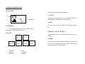
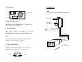
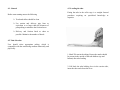
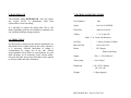
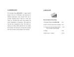
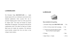
1. INTRODUCTION
2. CHECK LIST
The Peristaltic Pump RH-P100L-100 is a single channel
pump for the use in laboratory and extensively in
industrial applications where accurate flow rate is
essential. Pumping action is done by a roller cage driven
by stepper motor. The motor and internal are almost
independent of temperature. This pump has load and line
compensation circuit. The rollers are made up of carbon
Items included in the packing
1. Peristaltic Pump model RH-P100L-100
- 1 No.
2. 230v,4 A Power chord with 3 pin plug
- 1 No
3. Connector for External ON
- 1 No.
4. Tubing
- 1 Mtr
5. Spare Fuses ( 2 Amps)
- 2 No’s
filled nylon/S.S.316 for trouble free operation. The
electronic circuit provides constant flow rate even there is
line voltage or load variation.
3. GENERAL DESCRIPTION
3.1.Front Panel
Brief Description of the functional keys
.
a
.
1. ON/OFF
Pump Head
b
Using this key the pump can be switched ON/OFF. The
ON condition is indicated by a glowing LED.
2. Menu
This is used to select the RPM, ON time, Interval time
etc.
a. LCD Display
This Eight character Single Line Liquid Display
will show the RPM and Timer values.
3.DIG.SEL, 4.INC & 5.ENTER
b. Key Pad
These switches are used to set the desired flow rate and
timings
Dig.Sel
Inc
6.PRIME
ON/OFF
1. ON/OFF
2. MENU
3. DIG.SEL
Menu
Enter
4. INC
5. ENTER
6. PRIME
Prime
By keeping this switch in pressed condition the pump can
be run at its maximum speed. This switch will work only
when the pump is in OFF condition
3.2 .Rear Panel
4. OPERATION
b
a
Ensure Proper Earth for the Pump
Cooling Fan
c
NAME
PLATE
d
Earth (E)
a. Mains ON/OFF Switch
This switch is used to ON/OFF the A.C .Supply to the
pump. It has built in indication.
Line (L)
Neutral (N)
To 230v, 50/60Hz,
Single phase , AC
b. A.C.Main socket
This socket accepts the supply of A.C.230v,
50Hz.Suitable power chord is provided with the pump.
3 Core Cable
c.Fuse
Protects the electronics and the motor in case of short
circuiting. The Fuse rating is 1 Amps.
d. Foot Switch Terminal
The NO and Com points from the foot switch can be
connected to this terminal, for external control.
Foot Switch
NO
(Red)
To
Peristaltic Pump
E
COM
(Black)
N
L
4.1. General
4.3 .Loading the tube
Before start running ensure the following
Fitting the tube in the roller cage is a straight forward
procedure requiring no specialised knowledge or
expertise.
Track and rollers should be clean
Use suction and delivery pipe lines as
equivalent to or larger than the diameter of
pump tubing to minimise the friction losses.
Delivery and Suction lined as short as
possible. Minimise the number of bends.
4.2 Tube Selection
User should select appropriate tubing, which is
compatible with the transferring medium chemically and
physically.
1. Mark 250 mm in the tubing. Ensure the marks should
be present in the outside of the tube holders (top and
bottom) after tube loading
2. Pull back the tube holding lever in the suction side,
insert the tube and release the lever.
4.4. MENU FUNCTIONS
Menu
Step - 1
Step - 2
Step - 3
3. Rotate the roller cage in the clockwise direction so that
the tube is automatically in its path.
4.Fit the tube in the delivery side of the tube holding
mechanism as described in suction side.
5.Start the motor and confirm the smooth rotation of the
rollers over the tube.
NOTE: The rollers are set for 2mm wall thickness tubes.
If 1.5 mm wall thickness tube has to be used, Loosen the
screws provided in the sides of both the roller holding
plates uniformly by using the screw driver. Loosen the
screws until required pumping pressure is achieved.
RPM
ON time
Interval
Ela. Time
RESET
Forward/Reverse
1. RPM
- Speed – 00.01 to 99.99
2. On Time
- 01 Min. to 99 Hours, 59 Mins.
3. Interval
- 00.1 Sec. to 99.9 Sec.
4. Ela.Time
- Elapsed Time- Et. 99:59 (Max.)
5. RESET
- It reset the elapsed time
6. Forward/Reverse - This function is used to change
the direction of rotation of the
rotor
a. FLOW RATE SELECTION
1. RPM selection
2. RPM setting
The flow rate can be varied by changing the speed. The
speed of the pump head can be varied from 0.01 to 99.99.
The approximate flow rate can be selected by using the
output per revolution given below for various tubes.
1. Press the 'Menu' key, using the 'Inc' key, select
the '- RPM -' and press 'Enter'.
2. Using 'Dig.Sel'. switch, select the digit in the four
digit value.
The approximate ml/rev.:
5mm I.D. - 4 ml
6 mm I.D. - 6 ml
8 mm I.D. - 10 ml
10mm I.D. - 15 ml
12mm I.D. - 20 ml
3. The selected digit will blink.
4. When the digit is blinking, use the Inc. Key to
change the value from 0 to 9 as required.
The RPM for the required flow rate can be calculated as
follows
Flow rate(ml/min)
RPM =
ml/rev
Example:
1. For a flow rate of 60 ml/min in 6mm I.D.tubing
60
RPM =
= 10.0 (App.)
6
The exact quantity of the flow with respect to the RPM
has to be measured at the actual environment. Using this
output calculate the exact output per revolution and use
this calibrated value for further settings.
5. Then press the dig.sel. key once again to select
the next digit and set the desired value as
mentioned in points 2,3 & 4.
6. After the completion of
'Enter'.
RPM
entry, press
b. SETTING THE ON TIME
The ON TIME can be varied from 1 min to 99 hours. To
set the required ON TIME follow the procedure
mentioned below.
c. SETTING THE INTERVAL
The Interval time can be varied from 00.1 to 99.9 Sec.
To set the required Interval time, follow the procedure
mentioned below.
1. Press the 'Menu' switch and select the 'On Time'
mode using the 'Inc' key.
1. Press the 'Menu' switch and select the 'Interval' mode
using the 'Inc' key.
2. Using the Dig.Sel. switch select the the digit in
the four digit value.
2. Using the Dig.Sel. switch select the the digit in the
three digit value.
3. The selected digit will blink.
3. The selected digit will blink.
4. When the digit is blinking, use the Inc. Key to
change the value from 0 to 9 as required.
4. When the digit is blinking, use the Inc. Key to change
the value from 0 to 9 as required.
5. Then press the dig.sel. key once again to select
the next digit and set the desired value as
mentioned in points 3 & 4.
5. Then press the dig.sel. key once again to select the next
digit and set the desired value as mentioned in points
3 & 4.
Note:
Note:
If the Timer value is set at 00.00, then the pump will run
As a normal Peristaltic Pump with manual ON/OFF
If the Interval time is set at 00.0, Manual 'ON' is required
after the completion of ON time for the next cycle.
5. MAINTENANCE
7. TECHNICAL SPECIFICATIONS
The peristaltic pump RH-P100L-100 does not require
any regular service or maintenance other than
replacement of worn-out tubing.
No.of channel
:
One
Speed
:
00.01 to 99.99 RPM
Flow Rate
:
60ml to 60 Ltr./hr
It is advisable to replace the tubing after 300 to 500
Hours depending upon the environment ,to minimise the
risk of tubing breakage during operation.
Tubing
3 to 8 mm I.D
with 1.5 or 2 mm wall thickness
6 .LUBRICATION
No lubrication is required as the internal mechanisms are
lubricated for life. Lightly lubricate the rollers whenever
it is necessary. External lubrication of tubing is
recommended for longer life of the tube. Silicon
grease(midland silicon MS4 or equivalent)can be used
with advantage on all materials except silicon rubber.
Glycerin and other non-solvent lubricants can be applied
to silicone rubber and other elastomers.
:
On Time
:
1 min to 99 hours,59 Mins.
Interval Time
:
00.0 to 99.9 Sec
Motor
:
DC Stepper
Motor(Cont.Duty)
Supply
:
230v +/- 10%,50Hz A.C.
Temp. range
:
0 to 50 deg.C
Dimension
: 130 x 225 x 340mm
(H x W x D)
Weight
: 9 Kgs.(Approx.)
RH/UM/100L/001 Rev.00 20/11/06
PERISTALTIC PUMP
MODEL RH-P100L-100
USER'S MANUAL
RAVEL HITEKS PVT.LTD.,
150-A,ELECTRONIC INDUSTRIAL ESTATE
PERUNGUDI,CHENNAI –96
PH.:044-24960825, 24961004 FAX.: 4204 9599
e-mail: [email protected]
Web.: www.ravelhiteks.com