1
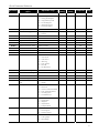
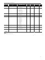
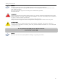
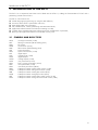
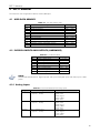
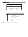
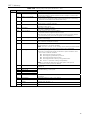
PLC11 Module Programming
Manual
Frequency Inverter
Series: CFW-11
Version: 1.0X
Language: English
Document: 10000118422 / 00
05/2008
Summary
1
SAFETY INSTRUCTIONS........................................................................................................................6
1.1
1.2
1.3
2
SAFETY WARNINGS IN THE MANUAL .......................................................................................... 6
SAFETY WARNINGS IN THE PRODUCT ......................................................................................... 6
PRELIMINARY RECOMMENDATIONS ............................................................................................ 6
GENERAL INFORMATION.....................................................................................................................8
2.1 ABOUT THE MANUAL...................................................................................................................... 8
ABBREVIATIONS AND DEFINITIONS .................................................................................................................. 8
NUMERICAL REPRESENTATION .......................................................................................................................... 8
2.2 COMPATIBILITY ................................................................................................................................ 8
3
INTRODUCTION TO THE PLC11...........................................................................................................9
3.1
4
SYMBOLS AND DATA TYPES........................................................................................................... 9
PLC11 MEMORY ................................................................................................................................10
4.1
4.2
USER DATA MEMORY..................................................................................................................... 10
PHYSICAL INPUTS AND OUTPUTS (HARDWARE) ..................................................................... 10
4.2.1 Analog Inputs.......................................................................................................................... 10
4.2.2 Analog Outputs....................................................................................................................... 11
4.3 SYSTEM MARKERS .......................................................................................................................... 11
5
PARAMETER SETTINGS .......................................................................................................................14
5.1
5.2
5.3
5.4
CFW-11 CONFIGURATION PARAMETERS .................................................................................. 14
PLC11 PARAMETERS....................................................................................................................... 14
ALARM DESCRIPTION.................................................................................................................... 30
FAULT DESCRIPTION ..................................................................................................................... 32
2
Quick Parameter Reference
Description
[Type]
Parameter
Adjustable range
Factory
setting
User
setting
Proprieties
Page
P1200
PLC11 Firmware Version
0 to 655.35
-
-
RO
14
P1201
PLC11 Status
0 = No Program
1 = Saving the Program
2 = Copy Memory Card
3 = Invalid Program
4 = Stopped Program
5 = Running Program
-
-
RO
15
P1202
Scan Cycle
0.0 to 6553.5 ms
-
-
RO
15
P1205
Actual Position (sign)
0 = Negative
1 = Positive
-
-
RO
15
P1206
Actual Position (turns)
-32768 to 32767 revolutions
-
-
RO
16
P1207
Actual Position (fraction)
0.0 to 359.9º
-
-
RO
16
P1208
Lag
0.0 to 6553.5º
-
-
RO
16
P1215
DI109 to DI101 Status
0000 to 01FFh
-
-
RO
16
P1216
DO106 to DO101 Status
0000 to 003Fh
-
-
RO
17
P1217
AI101 Value
-100.00 to 100.00 %
-
-
RO
17
P1218
AO101 Value
-100.00 to 100.00 %
-
-
RO
17
P1219
AO102 Value
-100.00 to 100.00 %
-
-
RO
18
P1220
CAN Status
0 = Inactive
1 = Auto-baud
2 = CAN Active
3 = Warning
4 = Error Passive
5 = Bus Off
6 = No Bus Power
-
-
RO
18
P1221
Received CAN Telegrams
0 to 65535
-
-
RO
18
P1222
Transmitted CAN Telegrams
0 to 65535
-
-
RO
18
P1223
Occurred CAN Errors
0 to 65535
-
-
RO
19
P1224
Lost CAN Telegrams
0 to 65535
-
-
RO
19
P1225
CANopen Configuration
State
0 = Slave
1 = Master
-
-
RO
19
P1226
CANopen Network Status
0 = Inactive
1 = Reserved
2 = Communication Enabled
3 = Error Control Enabled
4 = Guarding Error
5 = Heartbeat Error
-
-
RO
20
P1227
CANopen Node Status
0 = Inactive
1 = Initialization
2 = Stopped
3 = Operational
4 = Preoperational
-
-
RO
20
P1250
PLC11 Command
0 = Stop Program
1 = Run Program
2 = Delete Program
1
-
20
P1251
DI108 Interruption Enabling
0 = Disabled
1 = Falling Edge
2 = Rising Edge
0
-
21
3
Quick Parameter Reference
Parameter
Description
[Type]
P1252
DI109 Interruption Enabling
0 = Disabled
1 = Falling Edge
2 = Rising Edge
P1253
Time Interruption Period
0 to 65535 ms
P1254
PLC11 Watchdog
0 to 200 ms
P1255
Retentive Marker Reset
0 = Disabled
1 = Resets Markers
P1256
Load Parameters
P1257
Adjustable range
Factory
setting
User
setting
Proprieties
Page
0
-
21
0
-
21
200
-
22
0
-
22
0 = Disabled
1 = Loads Default
0
-
22
Copy Function Memory
Card
0 = Disabled
1 = Restore Program
2 = Restore Parameters
3 = Restore CAN
0
-
22
P1259
Maximum Lag
0.0 to 6553.5 º
180.0
-
23
P1260
Kp – Proportional
Positioning Gain
0 to 200
50
-
23
P1262
Main Encoder Resolution
0 to 4096 ppr
1024
-
23
P1263
Main Encoder Zero Pulse
0 to 359.9 º
0.0
-
24
P1264
Main Encoder Direction
0=A→B
1=B→A
1
-
24
P1265
Auxiliary Encoder Resolution
0 to 4096 ppr
1024
-
24
P1266
Auxiliary Encoder Zero Pulse
0 to 359.9 º
0.0
-
24
P1267
Auxiliary Encoder Direction
0=A→B
1=B→A
1
-
25
P1268
Auxiliary Encoder Position
Feedback
0 = Disabled
1 = Enabled
0
-
25
P1270
AI101 Gain
0.000 to 9.999
1.000
-
25
P1271
AI101 Signal
0 = 0 to 10 V / 20mA
1 = -10 to 10 V
2 = 4 to 20 mA
0
-
25
P1272
AI101 Offset
-100.00 to 100.00 %
0.00
-
26
P1273
AI101 Filter
0.00 to 16.00 s
0.00
-
26
P1274
AO101 Gain
0.000 to 9.999
1.000
-
26
P1275
AO101 Signal
0 = 0 to 10 V
1 = -10 to 10V
2 = 0 to 20 mA
3 = 4 to 20 mA
0
-
26
P1276
AO102 Gain
0.000 to 9.999
1.000
-
27
P1277
AO102 Signal
0 = 0 to 10 V
1 = -10 to 10V
2 = 0 to 20 mA
3 = 4 to 20 mA
0
-
27
P1280
Serial Protocol
0 = TP
1 = Modbus RTU
1
-
27
P1281
Serial Address
1 to 247
1
-
28
P1282
Serial Baud Rate
0 = 1200 bits/s
1 = 2400 bits/s
2 = 4800 bits/s
3 = 9600 bits/s
3
-
28
4
Quick Parameter Reference
Parameter
Description
[Type]
Adjustable range
Factory
setting
User
setting
Proprieties
Page
4 = 19200 bits/s
5 = 38400 bits/s
P1283
Serial Bytes Config.
0 = 8 bits, no, 1
1 = 8 bits, even, 1
2 = 8 bits, odd, 1
3 = 8 bits, no, 2
4 = 8 bits, even, 2
5 = 8 bits, odd, 2
0
-
28
P1285
CAN Protocol
0 = Disabled
1 = CANopen
0
-
29
P1286
CAN Address
0 to 127
63
-
29
P1287
CAN Baud Rate
0 = 1 Mbit/s
1 = Reserved
2 = 500 Kbit/s
3 = 250 Kbit/s
4 = 125 Kbit/s
5 = 100 Kbit/s
6 = 50 Kbit/s
7 = 20 Kbit/s
8 = 10 Kbit/s
0
-
29
P1288
CAN Bus off Recovery
0 = Manual
1 = Automatic
0
-
29
P1289
CAN Error Action
0 = Indicate Alarm
1 = Cause Fault
0
-
30
P1300
User Parameters
0000 to FFFFh
0
-
30
M
P1499
Note:
RO = Read-only parameter
5
Safety Instructions
1 SAFETY INSTRUCTIONS
This Manual contains the information necessary for the correct use of the CFW-11 variable frequency drive with the
PLC11 expansion board.
It has been developed to be used by qualified personnel with suitable training or technical qualification for
operating this type of equipment.
1.1 SAFETY WARNINGS IN THE MANUAL
DANGER!
The nonobservance of the procedures recommended in this warning can lead to death, serious injuries
or considerable equipment damage.
ATTENTION!
The nonobservance of the procedures recommended in this warning can lead to equipment damage.
NOTE!
The text aims at to supply important information for the correct understanding and good operation of
the product.
1.2 SAFETY WARNINGS IN THE PRODUCT
The following symbols are attached to the product as safety notes:
High voltages are present.
Components sensitive to electrostatic discharge.
Do not touch them.
Mandatory connection to the protective earth (PE)
Connection of the shield to the ground.
Hot surface.
1.3 PRELIMINARY RECOMMENDATIONS
DANGER!
Only qualified personnel familiar with the CFW-11 variable frequency drive and associated equipment
should plan or implement the installation, start-up and subsequent maintenance of this equipment
These personnel must follow all the safety instructions included in this Manual and/or defined by local
regulations.
Failure to comply with the safety instructions may result in death, serious injury, and equipment
damage.
6
Safety Instructions
NOTE!
For the purpose of this manual, qualified personnel are those trained and able to:
1. Install, ground, power-up, and operate the CFW-11 according to this manual and to the current
legal safety procedures;
2. Use the protection equipment according to the established regulations;
3. Provide first aid.
DANGER!
Always disconnect the input power before touching any electrical component associated to the inverter.
Many components can remain charged with high voltages or remain in movement (fans) even after that
AC power is disconnected or switched off.
Wait at least 10 minutes to assure a total discharge of the capacitors.
Always connect the equipment frame to the protection earth (PE) at the suitable connection point.
ATTENTION!
Electronic boards have components sensitive to electrostatic discharges. Do not touch directly on
components or connectors. If necessary, touch the grounded metallic frame before or use an adequate
grounded wrist strap.
Do not perform any high pot test with the inverter.
If necessary, consult WEG
NOTE!
Read the User Manual completely before installing or operating the CFW11.
7
General Information
2 GENERAL INFORMATION
2.1 ABOUT THE MANUAL
This manual provides the necessary description for the operation of the CFW-11 frequency inverter using the PLC11
expansion board. It must be used together with the CFW11 user manual and the WLP software manual.
Abbreviations and Definitions
PLC
CRC
RAM
WLP
USB
Programmable Logic Controller
Cycling Redundancy Check
Random Access Memory
Ladder language programming software
Universal Serial Bus
Numerical Representation
The decimal numbers are represented by means of digits without suffix. Hexadecimal numbers are represented with
the letter “h” after the number.
2.2 COMPATIBILITY
PLC11 V1.0X – CFW11 V1.3X or a version higher.
8
Introduction to the PLC11
3 INTRODUCTION TO THE PLC11
The PLC11 is an expansion board that can be fitted into the CFW-11, adding the functionalities of a PLC and a
positioning control to the CFW-11.
The PLC11 main features are:
Ladder language programming, by using the WLP software;
Access to all the CFW11 parameters and I/O’s;
200 configurable user parameters;
PLC, Mathematical, control, positioning and Movement blocks;
Applicative software transfer and online monitoring via USB;
Transfer of the installed applicative software to the PC conditioned to a password;
Backup of the applicative software in the FLASH memory card.
3.1 SYMBOLS AND DATA TYPES
%KW
%KF
%MX
%MW
%MF
%SX
%SW
%IX
%IW
%QX
%QW
%UW
%PW
%PD
%PM
%RW
%WW
%RB
%WB
%RS
%WS
word type constants (16 bit)
float type constants (32 bit floating point)
bit marker
word marker (16 bit)
float marker (32 bit floating point)
system bit marker
system word marker (16 bit)
digital inputs
analog inputs (16 bit)
digital outputs
analog outputs (16 bit)
user parameters (16 bit)
PLC11 system parameters (16 bit)
drive parameters (16 bit)
user block parameters (32 bit)
CANopen network reading word marker (16 bit)
CANopen network writing word marker (16 bit)
CANopen network reading byte marker (8 bit)
CANopen network writing byte marker (8 bit)
CANopen network reading status word marker (16 bit)
CANopen network writing command word marker (16bit)
9
PLC11 Memory
4 PLC11 MEMORY
The maximum size of applicative software is 327,680 bytes.
4.1 USER DATA MEMORY
Table 4.1 - User Date Memory Map
Sym.
%MX
%MX
%MW
%MW
%MF
%MF
%UW
%RW
%WW
%RB
%WB
Description
Retentive bit markers
Volatile bit markers
Retentive word markers
Volatile word markers
Retentive float markers
Volatile float markers
User parameters
CANopen network reading word markers
CANopen network Writing word markers
CANopen network reading Byte markers
CANopen network Writing Byte markers
Range
6100 ... 6483
6500 ... 7987
8200 ... 8399
8400 ... 8999
9200 ... 9399
9400 ... 9999
1300 ... 1499
4200 ... 4299
4600 ... 4699
4400 ... 4499
4800 ... 4899
4.2 PHYSICAL INPUTS AND OUTPUTS (HARDWARE)
Table 4.2 - I/O Memory Maps
Sym.
%IX
%IX
%QX
%QX
%IW
%IW
%QW
%QW
Description
CFW11 digital inputs
PLC11 digital inputs
CFW11 digital outputs
PLC11 digital outputs
CFW11 analog inputs
PLC11 analog inputs
CFW11 analog outputs
PLC11 analog outputs
Range
1 ... 6
101 ... 109
1 ... 3
101 ... 106
1 ... 2
101 ... 101
1 ... 2
101 ... 102
NOTE!
%IX108 and %IX109 (PLC11 digital inputs 8 and 9) are fast digital inputs and detect up to 10kHz
pulses.
4.2.1 Analog Inputs
Table 4.3 - Parameters Related to the Analog Inputs
Sym.
%IW1
Description
CFW11 Analog Input 1
(1 sign bit + 15 bits)
%IW2
CFW11 Analog Input 2
(1 sign bit + 15 bits)
%IW101
PLC11 Analog Input 1
(1 sign bit + 15 bits)
Related Parameters
P0231: Function
P0232: Gain
P0233: Signal
P0234: Offset
P0235: Filter
P0236: Function
P0237: Gain
P0238: Signal
P0239: Offset
P0240: Filter
P1270: Gain
P1271: Signal
P1272: Offset
P1273: Filter
10
PLC11 Memory
4.2.2 Analog Outputs
Table 4.4 - Parameters Related to the Analog Outputs
Sym.
%QW1
Description
CFW11 Analog Output 1
(1 sign bit + 15 bits)
%QW2
CFW11 Analog Output 2
(1 sign bit + 15 bits)
%QW101
PLC11 Analog Output 1
(1 sign bit + 15 bits)
PLC11 Analog Output 2
(1 sign bit + 15 bits)
%QW102
Related Parameters
P0251: Function
P0252: Gain
P0253: Signal
P0254: Function
P0255: Gain
P0256: Signal
P1274: Gain
P1275: Signal
P1276: Gain
P1277: Signal
4.3 SYSTEM MARKERS
Table 4.5.a - Memory Map of the System Bit Markers - Odd
Sym.
%SX
Address
Description
Writing/Command (odd)
3101
3103
General
Enabling
Run/Stop
3105
Speed Direction
3107
JOG
3109
LOC/REM
3111
Fault Reset
3121
Active Ramp
0:
1:
0:
1:
It disables the inverter, interrupting the supply for the motor.
It enables the inverter allowing the motor operation.
It stops the motor with deceleration ramp.
The motor runs according to the acceleration ramp until reaching
the speed reference value.
0: It runs the motor in the counterclockwise direction.
1: It runs the motor in the clockwise direction.
0: It disables the JOG function.
1: It enables the JOG function.
0: The inverter goes to the LOCAL situation.
1: The inverter goes to the REMOTE situation.
0: No function.
1: If in a fault condition, then it executes the inverter reset.
0: Ramp 1.
1: Ramp 2.
NOTE!
The system markers %SX3103 and %SX3105 do not have function when movement blocks are used,
because those commands are generated internally by these blocks.
11
PLC11 Memory
Table 4.5.b - Memory Map of the System Bit Markers – Even
Sym.
%SX
Address
Description
Reading/State (Even)
3000
General Enabling active
3002
Motor running (RUN)
3004
Speed Direction
3006
JOG
3008
LOC/REM
3010
Fault condition
3012
Undervoltage
3014
PID operation mode
3016
Alarm condition
3018
In configuration mode
3020
Active Ramp
3032
3034
3036
3038
3040
Start key (1)
Stop key (0)
Speed direction key (3)
Local/Remote key
JOG key
3064
3066
2Hz Blinker
Applicative Stop/Run
Trigger
Always 0
Always 1
3068
3070
0:
1:
0:
1:
General Enabling is not active.
General enabling is active and the inverter is ready to run the motor.
The motor is stopped.
The inverter is driving the motor at the set point speed, or executing
either the acceleration or the deceleration ramp.
0: The motor is rotating counterclockwise.
1: The motor is rotating clockwise.
0: JOG function inactive.
1: JOG function active.
0: Inverter in LOCAL situation.
1: Inverter in REMOTE situation.
0: The inverter is not in a fault condition.
1: Any fault has been registered by the inverter.
Note: The fault number can be read by means of the parameter P0049
(Current Fault) or by means of the system marker %SW3310.
0: No Undervoltage.
1: With Undervoltage.
0: In manual mode (PID function).
1: In automatic mode (PID function).
0: The inverter is not in an alarm condition.
1: The inverter is in an alarm condition.
Note: The alarm number can be read by means of the parameter P0048
(Current Alarm) or by means of the system marker %SW3308.
0: Inverter operating normally.
1: Inverter in configuration mode. It indicates a special condition when
the inverter cannot be enabled:
Executing the self tuning routine.
Executing the guided start-up routine.
Executing the HMI copy function.
Executing the flash memory card guided routine.
There is a parameter setting incompatibility.
Note: It is possible to obtain the exact description of the special
operation mode at parameter P0692.
0: Ramp 1.
1: Ramp 2.
0: Not pressed.
1: Pressed during 1 scan cycle.
0: Not pressed.
1: Pressed.
Alternates between 0 and 1 every 500ms
0: Normal condition.
1: Pulse when P1250 = 1
0: Fixed
1: Fixed
12
PLC11 Memory
Table 4.6 - Memory Map of the System Word Markers
Sym.
%SW
Address / Description
Reading markers/Status (Even)
3300
Motor speed in 13 bit
NOTE!
It uses a 13 bit resolution, i.e., 2000h is equal to the motor synchronous speed. Thus, for a VI pole motor
(1200 rpm synchronous speed) if the motor is at 600rpm, this marker will have a value of 4096.
(Speed_13bit)
x(Synch_Speed_rpm)
8912
(%SW3300)
Speed_rpm =
x(%SW3002)
8912
Speed_rpm =
3302
3304
3306
3308
3310
3400
3402
3404
3412
3414
3416
3418
Motor synchronous speed [rpm]
Motor speed [rpm]
Speed Reference [rpm]
Alarm
Fault
Speed – auxiliary encoder [rpm]
Control mode
0: Torque mode
1: Speed mode
2: Position mode
Elapsed scan cycles
Id current (+/- 100 %)
Iq current (+/- 100 %)
Id* current reference (+/- 100%)
Iq* current reference (+/- 100%)
13
Parameter Settings
5 PARAMETER SETTINGS
In the continuation, only the parameters of the CFW-11 frequency inverter that must be programmed according to
the PLC user program will be presented.
5.1 CFW-11 CONFIGURATION PARAMETERS
P0100 – Acceleration Time
P0101 – Deceleration Time
P0220 – LOCAL/REMOTE Selection Source
P0221 – Speed Reference Selection – LOCAL Situation
P0222 – Speed Reference Selection – REMOTE Situation
P0223 – FORWARD/REVERSE Selection - LOCAL Situation
P0224 – Run/Stop Selection – LOCAL Situation
P0225 – JOG Selection – LOCAL Situation
P0226 – FORWARD/REVERSE Selection - REMOTE Situation
P0227 – Run/Stop Selection - REMOTE Situation
P0228 – JOG Selection - REMOTE Situation
P0251 – AO1 Function
P0254 – AO2 Function
P0275 – DO1 Function (RL1)
P0276 – DO2 Function (RL2)
P0277 – DO3 Function (RL3)
5.2 PLC11 PARAMETERS
P1200 – PLC11 Firmware Version
Adjustable
Range:
0.00 to 655.35
Factory
Setting:
-
Proprieties: RO
Access groups via HMI:
01 PARAMETER GROUPS .
∟ 51 PLC11
l
∟ 130 System Parameters l
Description:
It indicates the PLC11 firmware version.
14
Parameter Settings
P1201 – PLC11 Status
0 = Without Program
1 = Saving the Program
2 = Copy Memory Card
3 = Invalid Program
4 = Stopped Program
5 = Running Program
Adjustable
Range:
-
Factory
Setting:
Proprieties: RO
Access groups via HMI:
01 PARAMETER GROUPS..
∟ 51 PLC11
l
∟ 130 System Parameters l
Description:
It allows the user to visualize the program status. See next the description of each state:
0: Without Program →
1: Saving the Program •
2: Copy Memory Card →
3: Invalid Program →
4: Stopped Program →
5: Running Program →
When the PLC11 does not have a program installed in its memory.
When the PLC11 is receiving a file from the WLP (User program, user parameter
configuration or CAN network configuration) or when the PLC11 is sending this file
to the WLP.
It occurs after the reception of a file from the WLP (User program, user parameter
configuration or CAN network configuration) during the backup of this file in the
CFW11 memory card. It also occurs when any option of P1257 (Copy Memory
Card Function) is executed.
When the user program is not compatible with the current PLC11 firmware version.
In this case it is necessary to download another program!
When there is a valid user program in the PLC11 memory, however, P1250
(PLC11 Command) is set with the option “Stop Program”.
When the user program is being executed.
P1202 – Scan Cycle
Adjustable
Range:
0.0 to 6553.5 ms
Factory Setting:
Proprieties: RO
Access groups via HMI:
01 PARAMETER GROUPS .
∟ 51 PLC11
l
∟ 130 System Parameters l
Description:
It allows the user to monitor the program scan cycle.
P1205 – Actual Position (sign)
Adjustable
Range:
0 to 1
Factory
Setting:
-
Proprieties: RO
Access groups via HMI:
01 PARAMETER GROUPS..
∟ 51 PLC11
l
∟ 130 System Parameters l
Description:
It informs the sign of the motor current position. 0 means positive and 1 means negative.
15
Parameter Settings
P1206 – Actual Position (turns)
Adjustable
Range:
-32768 to 32767 revolutions
-
Factory
Setting:
Proprieties: RO
Access groups via HMI:
01 PARAMETER GROUPS.
∟ 51 PLC11
l
∟ 130 System Parameters
l
Description:
It informs the number of revolutions of the current motor position.
P1207 – Actual Position (fraction)
Adjustable
Range:
0 to 359.9 º
Factory
Setting:
-
Proprieties: RO
Access groups via HMI:
01 PARAMETER GROUPS..
∟ 51 PLC11
l
∟ 130 System Parameters l
Description:
It informs the revolution fraction, in degrees, of the current motor position.
P1208 – Lag
Adjustable
Range:
0 to 6553.5 º
Factory
Setting:
-
Proprieties: RO
Access groups via HMI:
01 PARAMETER GROUPS..
∟ 51 PLC11
l
∟ 130 System Parameters
l
Description:
It informs the difference, in degrees, between the position reference and the actual position.
P1215 – DI109 to DI101 Status
Adjustable
Range:
0000 to 01FFh
Factory
Setting:
-
Proprieties: RO
Access groups via HMI:
01 PARAMETER GROUPS..
∟ 51 PLC11
l
∟ 130 System Parameters
l
Description:
It Informs the PLC11 digital input status:
- Bit 0: DI101 (least significant bit)
- Bit 1: DI102
- Bit 2: DI103
- Bit 3: DI104
- Bit 4: DI105
16
Parameter Settings
- Bit 5: DI106
- Bit 6: DI107
- Bit 7: DI108
- Bit 8: DI109 (most significant bit)
P1216 – DO106 to DO101 Status
0000 to 003Fh
Adjustable
Range:
-
Factory
Setting:
Proprieties: RO
Access groups via HMI:
01 PARAMETER GROUPS..
∟ 51 PLC11
l
∟ 130 System Parameters l
Description:
It informs the PLC11 digital output status:
- Bit 0: DO101 (least significant bit)
- Bit 1: DO102
- Bit 2: DO103
- Bit 3: DO104
- Bit 4: DO105
- Bit 5: DO106 (most significant bit)
P1217 – AI101 Value
-100.00 to 100.00 %
Adjustable
Range:
Factory
Setting:
-
Proprieties: RO
Access groups via HMI:
01 PARAMETER GROUPS..
∟ 51 PLC11
l
∟ 130 System Parameters
l
Description:
It informs the value read at the analog input 101, in percentage, after the gain and offset calculation and the filter
action.
P1218 – AO101 Value
-100.00 to 100.00 %
Adjustable
Range:
Proprieties:
Factory
Setting:
-
RO
Access groups via HMI:
01 PARAMETER GROUPS..
∟ 51 PLC11
l
∟ 130 System Parameters
l
Description:
It informs the value at the analog output 101, in percentage, after the gain and offset calculation.
17
Parameter Settings
P1219 – AO102 Value
-100.00 to 100.00 %
Adjustable
Range:
-
Factory
Setting:
Proprieties: RO
Access groups via HMI:
01 PARAMETER GROUPS..
∟ 51 PLC11
l
∟ 130 System Parameters
l
Description:
It informs the value at the analog output 102, in percentage, after the gain and offset calculation.
P1220 – CAN Status
0 = Inactive
1 = Auto-baud
2 = CAN Active
3 = Warning
4 = Error Passive
5 = Bus Off
6 = No Bus Power
Adjustable
Range:
Proprieties:
-
Factory
Setting:
RO
Access groups via HMI:
01 PARAMETER GROUPS..
∟ 51 PLC11
l
∟ 130 System Parameters
l
Description:
It informs the CAN network current status.
P1221 – Received CAN Telegrams
0 to 65535
Adjustable
Range:
Proprieties:
Factory
Setting:
-
RO
Access groups via HMI:
01 PARAMETER GROUPS..
∟ 51 PLC11
l
∟ 130 System Parameters
l
Description:
It informs the number of telegrams received through the CAN network.
P1222 – Transmitted CAN Telegrams
0 to 65535
Adjustable
Range:
Proprieties:
Factory
Setting:
-
RO
Access groups via HMI:
01 PARAMETER GROUPS..
∟ 51 PLC11
l
∟ 130 System Parameters l
18
Parameter Settings
Description:
It informs the number of telegrams transmitted through the CAN network.
P1223 – Occurred CAN Errors
0 to 65535
Adjustable
Range:
-
Factory
Setting:
Proprieties: RO
Access groups via HMI:
01 PARAMETER GROUPS..
∟ 51 PLC11
l
∟ 130 System Parameters
l
Description:
It informs the number of errors occurred in the CAN network.
P1224 – Lost CAN Telegrams
0 to 65535
Adjustable
Range:
Proprieties:
Factory
Setting:
-
RO
Access groups via HMI:
01 PARAMETER GROUPS..
∟ 51 PLC11
l
∟ 130 System Parameters
l
Description:
It informs the number of lost telegrams in the CAN network.
P1225 – CANopen Configuration State
Adjustable
Range:
0 = Slave
1 = Master
Factory
Setting:
-
Proprieties: RO
Access groups via HMI:
01 PARAMETER GROUPS..
∟ 51 PLC11
l
∟ 130 System Parameters l
Description:
It informs the configuration state of the CANopen network. For more information on the CAN interface and on the
CANopen protocol, refer to the CANopen communication and the PLC11 board manuals.
19
Parameter Settings
P1226 – CANopen Network Status
Adjustable
Range:
Proprieties:
0 = Inactive
1 = Reserved
2 = Communication Enabled
3 = Error Control Enabled
4 = Guarding Error
5 = Heartbeat Error
-
Factory
Setting:
RO
Access groups via HMI:
01 PARAMETER GROUPS..
∟ 51 PLC11
l
∟ 130 System Parameters
l
Description:
It informs the state of the CANopen network. For more information on the CAN interface and on the CANopen
protocol, refer to the CANopen communication and the PLC11 board manuals.
P1227 – CANopen Node Status
Adjustable
Range:
0 = Inactive
1 = Initialization
2 = Stopped
3 = Operational
4 = Preoperational
Factory
Setting:
-
Proprieties: RO
Access groups via HMI:
01 PARAMETER GROUPS..
∟ 51 PLC11
l
∟ 130 System Parameters l
Description:
It informs the state of the CANopen network node. For more information on the CAN interface and on the
CANopen protocol, refer to the CANopen communication and the PLC11 board manuals.
P1250 – PLC11 Command
Adjustable
Range:
0 = Stop Program
1 = Run Program
2 = Delete Program
Factory
Setting:
1
Proprieties:
Access groups via HMI:
01 PARAMETER GROUPS..
∟ 51 PLC11
l
∟ 130 System Parameters
l
Description:
It makes it possible for the user to stop the installed applicative, execute it, or delete it.
20
Parameter Settings
P1251 – DI108 Interruption Enabling
Adjustable
Range:
0 = Disabled
1 = Falling Edge
2 = Rising Edge
Factory
Setting:
0
Proprieties:
Access groups via HMI:
01 PARAMETER GROUPS..
∟ 51 PLC11
|
∟ 130 System Parameters |
Description:
It allows the user to configure the digital input 108 to generate an interruption in the main user program, starting
the execution of the program responsible for the use of this fast input. The detection can be configured for falling or
rising edge.
P1252 – DI109 Interruption Enabling
Adjustable
Range:
0 = Disabled
1 = Falling Edge
2 = Rising Edge
Factory
Setting:
0
Proprieties:
Access groups via HMI:
01 PARAMETER GROUPS..
∟ 51 PLC11
l
∟ 130 System Parameters
l
Description:
It allows the user to configure the digital input 109 to generate an interruption in the main user program, starting
the execution of the program responsible for the use of this fast input. The detection can be configured for falling or
rising edge.
P1253 – Time Interruption Period
Adjustable
Range:
0 to 65535 ms
Factory
Setting:
0
Proprieties:
Access groups via HMI:
01 PARAMETER GROUPS..
∟ 51 PLC11
l
∟ 130 System Parameters
l
Description:
It allows the user to configure a time period for the PLC11 to generate an interruption in the main user program,
starting the execution of the program responsible for the use of this time interruption. If this parameter is set to zero,
then the time interruption is disabled.
21
Parameter Settings
P1254 – PLC11 Watchdog
Adjustable
Range:
0 to 200 ms
Factory
Setting:
200
Proprieties:
Access groups via HMI:
01 PARAMETER GROUPS..
∟ 51 PLC11
l
∟ 130 System Parameters
l
Description:
It is the maximum time allowed for a total scan of the main program. If the scan time exceeds this limit, then the
PLC11 watchdog fault occurs.
P1255 – Retentive Marker Reset
Adjustable
Range:
0 = Disabled
1 = Resets Markers
Factory
Setting:
0
Proprieties:
Access groups via HMI:
01 PARAMETER GROUPS..
∟ 51 PLC11
l
∟ 130 System Parameters
l
Description:
It allows the user to reset the retentive markers applied in the user program.
P1256 – Load Parameters
Adjustable
Range:
0 = Disabled
1 = Loads Factory Settings
Factory
Setting:
0
Proprieties:
Access groups via HMI:
01 PARAMETER GROUPS..
∟ 51 PLC11
l
∟ 130 System Parameters
l
Description:
It allows the user to load the PLC11 parameters PLC11 (1200 to 1499) with the factory settings.
P1257 – Copy Memory Card Function
Adjustable
Range:
0 = Disabled
1 = Restore Program
2 = Restore Parameters
3 = Restore CAN
Factory
Setting:
0
Proprieties:
Access groups via HMI:
01 PARAMETER GROUPS..
∟ 51 PLC11
l
∟ 130 System Parameters
l
Description:
It allows the user to restore the file containing:
- Applicative;
- User parameter configurations:
- CAN network configurations.
22
Parameter Settings
In case it is installed in the CFW11 flash memory card.
Every time any of the files mentioned above is transferred from the WLP to the PLC11, a backup in the flash memory
card is automatically performed, unless the card is not connected to the inverter or it is defective.
P1259 – Maximum Lag
Adjustable
Range:
0.0 to 6553.5º
Factory
Setting:
180.0
Proprieties:
Access groups via HMI:
01 PARAMETER GROUPS..
∟ 51 PLC11
l
∟ 130 System Parameters
l
Description:
It is the maximum allowed error between the position reference and the actual position, without a fault trip in the
inverter.
NOTE!
It acts when the inverter is executing positioning tasks.
P1260 – Kp – Proportional Positioning Gain
Adjustable
Range:
0 to 200
Factory
Setting:
50
Proprieties:
Access groups via HMI:
01 PARAMETER GROUPS..
∟ 51 PLC11
l
∟ 130 System Parameters
l
Description:
PLC11 positioning controller gain.
NOTE!
It acts when the inverter is executing positioning tasks.
P1262 – Main Encoder Resolution
Adjustable
Range:
0 to 4096
Factory
Setting:
1024
Proprieties:
Access groups via HMI:
01 PARAMETER GROUPS..
∟ 51 PLC11
l
∟ 130 System Parameters
l
Description:
It defines the resolution of the PLC11 main encoder.
23
Parameter Settings
P1263 – Main Encoder Marker
Adjustable
Range:
0.0 to 359.9°
Factory
Setting:
0.0
Factory
Setting:
1
Proprieties:
Access groups via HMI:
01 PARAMETER GROUPS..
∟ 51 PLC11
l
∟ 130 System Parameters
l
Description:
It allows the PLC11 to shift the main encoder marker position via software.
P1264 – Main Encoder Direction
Adjustable
Range:
0=A→B
1=B→A
Proprieties:
Access groups via HMI:
01 PARAMETER GROUPS..
∟ 51 PLC11
l
∟ 130 System Parameters
l
Description:
It defines the direction of the main encoder pulses.
P1265 – Auxiliary Encoder Resolution
Adjustable
Range:
0 to 4096
Factory
Setting:
1024
Factory
Setting:
0.0
Proprieties:
Access groups via HMI:
01 PARAMETER GROUPS..
∟ 51 PLC11
l
∟ 130 System Parameters
l
Description:
It defines the resolution of the PLC11 auxiliary encoder.
P1266 – Auxiliary Encoder Marker
Adjustable
Range:
0.0 to 359.9°
Proprieties:
Access groups via HMI:
01 PARAMETER GROUPS..
∟ 51 PLC11
l
∟ 130 System Parameters
l
Description:
It allows the PLC11 to shift the auxiliary encoder marker position via software.
24
Parameter Settings
P1267 – Auxiliary Encoder Direction
Adjustable
Range:
0=A→B
1=B→A
Factory
Setting:
1
Proprieties:
Access groups via HMI:
01 PARAMETER GROUPS..
∟ 51 PLC11
l
∟ 130 System Parameters
l
Description:
It defines the direction of the auxiliary encoder pulses.
P1268 – Auxiliary Encoder Position Feedback
Adjustable
Range:
0 = Disabled
1 = Enabled
Factory
Setting:
0
Proprieties:
Access groups via HMI:
01 PARAMETER GROUPS..
∟ 51 PLC11
|
∟ 130 System Parameters |
Description:
When this option is enabled, the position feedback is done by the auxiliary encoder.
P1270 – AI101 Gain
Adjustable
Range:
0.000 to 9.999
Factory
Setting:
1.000
Proprieties:
Access groups via HMI:
01 PARAMETER GROUPS..
∟ 51 PLC11
l
∟ 130 System Parameters
l
Description:
It is the value that is multiplied by the sum of the PLC11 analog input 101 content and its Respective offset (P1272).
P1271 – AI101 Signal
Adjustable
Range:
0 = 0 to 10V / 20 mA
1 = -10 to 10V
2 = 4 to 20mA
Factory
Setting:
0
Proprieties:
Access groups via HMI:
01 PARAMETER GROUPS..
∟ 51 PLC11
l
∟ 130 System Parameters
l
Description:
It configures the type of signal (current or voltage) that will be read at the PLC11 analog input 101, as well as its
variation range.
NOTE!
It is also necessary to set the S3 switch in order to select the type of signal. OFF for voltage and ON for
current.
25
Parameter Settings
P1272 – AI101 Offset
Adjustable
Range:
-100.00 to 100.00%
Factory
Setting:
0.00
Factory
Setting:
0.00
Factory
Setting:
1.000
Proprieties:
Access groups via HMI:
01 PARAMETER GROUPS..
∟ 51 PLC11
l
∟ 130 System Parameters
l
Description:
It adds an offset to the content of the PLC11 analog input 101.
P1273 – AI101 Filter
Adjustable
Range:
0.00 to 16.00s
Proprieties:
Access groups via HMI:
01 PARAMETER GROUPS..
∟ 51 PLC11
|
∟ 130 System Parameters |
Description:
The value of the PLC11 analog input 101 respects the following equation:
P1272
%IW101 = ⎛AI1_PLC11 + 100 x 10V ⎞ x P1270
⎝
⎠
This parameter defines the time constant of the PLC11 analog input 101 filter.
P1274 – AO101 Gain
Adjustable
Range:
0.000 to 9.999
Proprieties:
Access groups via HMI:
01 PARAMETER GROUPS..
∟ 51 PLC11
l
∟ 130 System Parameters
l
Description:
It is the value multiplied by the content to be written at the PLC11 analog output 101.
P1275 – AO101 Signal
Adjustable
Range:
0 = 0 to 10V
1 = -10 to 10V
2 = 0 to 20mA
3 = 4 to 20mA
Factory
Setting:
0
Proprieties:
Access groups via HMI:
01 PARAMETER GROUPS..
∟ 51 PLC11
l
∟ 130 System Parameters
l
26
Parameter Settings
Description:
It configures the type of signal (current or voltage) that will be written at the PLC11 analog output 101, as well as its
variation range.
NOTE!
It is also necessary to set the S2:1 switch in order to select the voltage variation range. OFF for 0
to 10V and ON for -10 to 10V.
P1276 – AO102 Gain
Adjustable
Range:
0.000 to 9.999
1.000
Factory
Setting:
Proprieties:
Access groups via HMI:
01 PARAMETER GROUPS..
∟ 51 PLC11
l
∟ 130 System Parameters
l
Description:
It is the value multiplied by the content to be written at the PLC11 analog output 102.
P1277 – AO102 Signal
Adjustable
Range:
0 = 0 to 10V
1 = -10 to 10V
2 = 0 to 20mA
3 = 4 to 20mA
Factory
Setting:
0
Proprieties:
Access groups via HMI:
01 PARAMETER GROUPS..
∟ 51 PLC11
l
∟ 130 System Parameters l
Description:
It configures the type of signal (current or voltage) that will be written at the PLC11 analog output 102, as well as its
variation range.
NOTE!
It is also necessary to set the S2:2 switch in order to select the voltage variation range. OFF for 0 to
10V and ON for -10 to 10V.
P1280 – Serial Protocol
Adjustable
Range:
0 = TP
1 = Modbus RTU
Factory
Setting:
1
Proprieties:
Access groups via HMI:
01 PARAMETER GROUPS..
∟ 51 PLC11
l
∟ 130 System Parameters
l
Description:
It configures the RS-485 interface communication protocol.
27
Parameter Settings
P1281 – Serial Address
Adjustable
Range:
1 to 247
1
Factory
Setting:
Proprieties:
Access groups via HMI:
01 PARAMETER GROUPS..
∟ 51 PLC11
l
∟ 130 System Parameters
l
Description:
It sets the address of the RS-485 interface in the communication network of this PLC11 board.
P1282 – Serial Baud Rate
Adjustable
Range:
0 = 1200 bits/s
1 = 2400 bits/s
2 = 4800 bits/s
3 = 9600 bits/s
4 = 19200 bits/s
5 = 38400 bits/s
Factory
Setting:
3
Proprieties:
Access groups via HMI:
01 PARAMETER GROUPS..
∟ 51 PLC11
l
∟ 130 System Parameters
l
Description:
It adjusts the RS-485 interface baud rate.
P1283 – Serial Bytes Configuration
Adjustable
Range:
0 = 8 bits, no, 1
1 = 8 bits, even, 1
2 = 8 bits, odd, 1
3 = 8 bits, no, 2
4 = 8 bits, even, 2
5 = 8 bits, odd, 2
Factory
Setting:
0
Proprieties:
Access groups via HMI:
01 PARAMETER GROUPS..
∟ 51 PLC11
l
∟ 130 System Parameters
l
Description:
It sets the number of bits, the parity, and the number of stop bits of the RS-485 interface.
28
Parameter Settings
P1285 – CAN Protocol
Adjustable
Range:
0 = Disabled
1 = CANopen
Factory
Setting:
0
Proprieties:
Access groups via HMI:
01 PARAMETER GROUPS..
∟ 51 PLC11
l
∟ 130 System Parameters
l
Description:
It configures the network communication protocol. For more information on the CAN interface and on the
CANopen protocol, refer to the CANopen communication and the PLC11 board manuals.
P1286 – CAN Address
Adjustable
Range:
0 to 127
Factory
Setting:
63
Proprieties:
Access groups via HMI:
01 PARAMETER GROUPS..
∟ 51 PLC11
l
∟ 130 System Parameters
l
Description:
It configures the address in the CAN network.
P1287 – CAN Baud Rate
Adjustable
Range:
0 = 1 Mbit/s
1 = Reserved
2 = 500 Kbit/s
3 = 250 Kbit/s
4 = 125 Kbit/s
5 = 100 Kbit/s
6 = 50 Kbit/s
7 = 20 Kbit/s
8 = 10 Kbit/s
Factory
Setting:
0
Factory
Setting:
1
Proprieties:
Access groups via HMI:
01 PARAMETER GROUPS..
∟ 51 PLC11
l
∟ 130 System Parameters l
Description:
It configures the baud rate of the CAN network.
P1288 – CAN Bus off Recovery
Adjustable
Range:
0 = Manual
1 = Automatic
Proprieties:
Access groups via HMI:
01 PARAMETER GROUPS..
∟ 51 PLC11
l
∟ 130 System Parameters
l
29
Parameter Settings
Description:
It configures the way the PLC11 recovers when a Bus Off occurs in the CAN network.
P1289 – CAN Error Action
0 = Alarm
1 = Fault
Adjustable
Range:
Factory
Setting:
0
Factory
Setting:
0
Proprieties:
Access groups via HMI:
01 PARAMETER GROUPS..
∟ 51 PLC11
l
∟ 130 System Parameters
l
Description:
It configures how the CAN network must react if any error occurs.
P1300 – User Parameters
M
P1499 – User Parameters
0 to FFFFh
Adjustable
Range:
Proprieties:
Configured via WLP
Access groups via HMI:
01 PARAMETER GROUPS..
∟ 51 PLC11
l
∟ 131 User Parameters
l
Description:
They are general purpose user parameters.
5.3 ALARM DESCRIPTION
Alarm
Description
Possible Causes and Recommendations
A162:
Incompatible PLC
Firmware
A163:
Break Detect AI1
It signalizes that the firmware of the PLC11 and the
CFW-11 are incompatible.
Incompatible firmware versions of the PLC11
and of the CFW-11.
It indicates that the AI1 current (4-20mA or 20-4mA)
reference is out of the 4 to 20mA range.
Broken AI1 cable;
Bad contact at the signal connection to the
terminal strip.
A164:
Break Detect AI2
It indicates that the AI2 current (4-20mA or 20-4mA)
reference is out of the 4 to 20mA range.
Broken AI2 cable;
Bad contact at the signal connection to the
terminal strip.
A165:
Break Detect AI3
It indicates that the AI3 current (4-20mA or 20-4mA)
reference is out of the 4 to 20mA range.
A166:
Break Detect AI4
It indicates that the AI4 current (4-20mA or 20-4mA)
reference is out of the 4 to 20mA range.
Broken AI3 cable;
Bad contact at the signal connection to the
terminal strip.
Broken AI4 cable;
Bad contact at the signal connection to the
terminal strip.
A700:
Detached HMI
Refer to the SoftPLC Manual.
A702:
Inverter Disabled
Refer to the SoftPLC Manual.
A704:
Two Movements Enabled
Refer to the SoftPLC Manual.
30
Parameter Settings
Alarm
A706:
Not Programmed
Reference SoftPLC
A8061:
CAN Without Supply
A8081:
Bus Off
A8101:
CANopen
Communication Error
A816:
Axis not Referenced
Description
Possible Causes and Recommendations
Refer to the SoftPLC Manual.
A CAN protocol was enabled through the parameter
P1280, but there is no 24V supply at the interface.
For more information refer to the PLC11
CANopen communication manual.
A buss off error was detected at the CAN interface.
For more information refer to the PLC11
CANopen communication manual.
The CANopen protocol error control has detected
communication error.
For more information refer to the PLC11
CANopen communication manual.
Use the HOME block to perform the search
of the machine home position.
A818:
Two Enabled Movements
It happens in the attempt to execute an absolute
positioning without the execution previously of the
home position routine.
It occurs when 2 or more positioning or movement
blocks are being enabled simultaneously.
A820:
Invalid Movement Data
It occurs when there is any incorrect value for speed,
acceleration, etc.
A822:
Disabled Inverter
It occurs when a positioning or a movement block is
activated and the inverter is not enabled.
A824:
Disconnected HMI
It occur s when an RTC block is activated and the HMI
is not connected to the inverter.
NOTE!
The real time clock – RTC – is in the HMI.
It occurs when there was an error in the transmission
of the PLC11 user program.
A826:
Wrong CRC
A828:
Memory Card Timeout
A830:
Invalid PLC11 Application
A832:
Stopped PLC11
Application
A834: Disconnected
Memory Card
A836:
Motor Running
A838:
Speed reference not
programmed for PLC
A840:
Broken wire at AI101
It occurs when the CFW11 flash memory card takes
more than 50ms to answer to the PLC11;
It occurs when the CFW11 flash memory card has not
accepted the PLC11 command.
It appears when the PLC11 is installed in the CFW11
and there is no user program installed, or the user
program is incompatible with the current PLC11
version.
It occurs when there is a valid user program in the
PLC11 board and the PLC11 command (P1250) is in
“Stop Prog.”
Create interlocking logics in order to avoid
simultaneous activation of positioning or
movement blocks.
Verify which is the parameter or marker that is
being used for the configuration of the speed
or the acceleration of a positioning block that
contains a value equal to 0.
Analyze whether the user program contains
the programming regarding the drive
enabling through the system marker
%SX3101.
Verify whether the inverter is configured in the
local mode or in the remote mode, so that
the PLC11 has control over the logic
command.
Verify whether the HMI is properly connected
to the inverter.
Retransmit it again.
Analyze noise issues.
Verify whether the CFW11 flash memory
card is correctly connected to the CFW11.
It may occur when there is a PLC11 firmware
updating.
Retransmit the user program.
Set P1250 to (1) “Run Prog.”
It happens during the Copy function (P1257) or while
transferring a file from the WLP to the PLC11, if the
CFW11 flash memory card is not connected.
Verify whether the flash memory card is
correctly connected to the CFW11.
It occurs if during the Copy function (P1257) or
during the transferring of a WLP file to the inverter, the
inverter is sending a command to run the motor.
It occurs when a positioning or a movement block is
enabled, but the speed reference is not configured for
PLC11 (P0221 or P0222).
Disable the inverter during the Copy function
or during the transferring of a WLP file to the
PLC11.
Configure the parameter P0221 or P0222
so that the PLC11 generates the reference
for the inverter.
It occurs when the signal type configured for the
PLC11 analog input 101 (P1271) is 4 to 20mA, but
the read signal is lower than 2mA.
Verify the PLC11 AI101 wiring.
Verify whether the wire has been broken.
1
These events are considered alarms only if the parameter P1289 is programmed with the option “0: Alarm”. Further information on these
alarms can be obtained in the CANopen communication manual for the PLC11.
31
Parameter Settings
5.4 FAULT DESCRIPTION
Fault
F161:
Timeout PLC11
CFW-11
F185:
Precharge Contac
Fault
Description
Possible Causes and Recommendations
It signalizes the communication loss between
the PLC11 board and the CFW11.
It indicates fault at the Pre-charge Contactor.
Bad contact at the connection between the
PLC11 and the CFW11;
Problems in the applicative software;
Defective PLC11 board.
Pre-charge contactor defect.
F228:
Serial Communication
Timeout
Refer to the RS-232 / RS-485 Serial Communication Manual.
F229:
Anybus Offline
Refer to the Anybus-CC Communication Manual.
F230:
Anybus Access Error
Refer to the Anybus-CC Communication Manual.
F233:
CAN Bus Power
Failure
Refer to the CANopen Communication Manual and/or the DeviceNet Communication Manual.
F234:
Bus Off
Refer to the CANopen Communication Manual and/or the DeviceNet Communication Manual.
F235:
CANopen
Communication Error
Refer to the CANopen Communication Manual.
F236:
Master Idle
Refer to the DeviceNet Communication Manual.
F237:
DeviceNet Connect
Timeout
Refer to the DeviceNet Communication Manual.
F701:
Detached HMI
Refer to the SoftPLC Manual.
F8072:
CAN Without Supply
A CAN protocol was enabled through the
parameter P1280, but there is no 24V supply at
the interface.
For more information refer to the PLC11
CANopen communication manual.
F8092:
Bus Off
A buss off error was detected at the CAN
interface.
For more information refer to the PLC11
CANopen communication manual.
F8112:
CANopen
Communication Error
The CANopen protocol error control has
detected communication error.
For more information refer to the PLC11
CANopen communication manual.
F817:
Lag Error
It occurs when the difference between reference
and the actual position exceeds the error
programmed in P1259.
The acceleration value is higher than the
recommended for the system.
Verify whether the encoder is wired correctly.
F821:
Invalid PLC Firmware
It occurs when the firmware CRC is not valid.
This prevents the operation of the PLC11.
Try cycling the power of the equipment.
Request to WEG the replacement of this
equipment firmware.
F823:
Disconnected HMI
It occurs when an RTC block has been enabled
and the HMI is not connected to the inverter.
NOTE!
The real time clock is in the HMI.
Verify whether the HMI is properly connected
to the inverter.
F825:
PLC11 Flash Fault
It may occur by enabling the Copy function
(P1257) or during the transferring of any file
from the PC to the PLC11.
Try executing the operation again.
2
These events will be considered faults only if the parameter P1289 were programmed with the option “1 – Fault”. Further information on
these faults can be obtained in the CANopen communication manual for the PLC11.
32
Parameter Settings
Fault
Description
Possible Causes and Recommendations
F827:
Memory Card with
Invalid Data
It occurs when the Copy function (P1257) is
enabled and data contained in the flash
memory board is not valid or is incompatible
with the correct PLC11 firmware version.
Retransmit the user program.
F829:
PLC11Watchdog
Internal error in the PLC11 applicative.
Interruption Ladder applicative too big or with a
high calling frequency.
It occurs when the Copy function (P1257) is
enabled and data contained in the flash
memory board is not valid or is incompatible
with the correct PLC11 firmware version.
Change the calling period of the interruptions.
Reduce the size of the interruption programs.
NOTE!
The range from 950 up to 999 is destined to the user faults and alarms.
33