1
THE 100
APPLICATIONS NEWSLETIER
VOL. 6 NO. 4
WINTER 1982
Tekniques
)
COMMIT TED TO EXCELLENCE
Tekniques
In This Issue
Architectural Firm Expands Without
Adding Staff
Solution Vendor Program
Product Design, Engineering and
Manufacturing
Data Representation
Architecture/Facilities
Bringing Computers into the Chemistry
Lab at SUNY at Cobleskill Inspires
Students and Fac~lty
4110 Local Programmability Brings
Distributed Processing to Graphics
Applications
2
4
4
4
5
6
10
4052 Helps Reveal Secrets of
Antarctica Data
PLOT 50 2-D Drafting New Release
Offers Increased Performance for
Automated Drafting
PLOT 50 Software Supports 4909
Hard Disk
14
New 4907 ROM Pack Enhances and
Adds Commands
Input/ Output
15
15
Crisp Images, Vibrant Colors
Distinguish New Color Copier
16
Tektronix GPIB Extender Stretches
the Data Link
Editor's Note
18
19
12
14
4050 Series Graphic Systems
Workshops Scheduled
19
Programming Tips
20
Basic Bits
24
25
New Abstracts
Program Updates
29
IDD Graphic Displays and Computing
System Publications
Library Addresses
30
32
TEKniques, the IDD Applications Newsletter, is published in the Information
Display Division of Tektronix, Inc., Group
451, P.O. Box 500, Beaverton, Oregon
97077. It is distributed to TEKTRONIX
computer and terminal users.
Publishing Manager
Managing Editor
Technical Editor
Graphic Design
Circulation
Typesetting
Architectural Firm Expands
Without Adding Staff
Ken Cramer
Patricia Kelley
Dan Taylor
John Ellis
Rory Gugliotta
Jean Bunker
Copyright © 1982, Tektronix, Inc.
All rights reserved.
To submit artici€s to TEKniques or for information on reprintingarticies, write to
the above address. Changes of address
should be sent to the IDD Library serving
your area (see Library addresses).
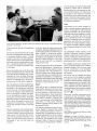
Familiar, friendly, powerful, a natural fit ...
Rollin Gardner expressed his pleasure for his
recently acquired computer aided design and
drafting system.
A commercial architectural firm, Gardner
Associates-Architects, Inc. works with a range
of projects from small office buildings of
3000 to 4000 square feet up to six story medical buildings. Shopping centers and banks also
form a large part of their portfolio.
As with many firms in the greater Houston
area, work for Gardner Associates is growing. But it's tough for a four-member firm to
compete against larger firms for big projects.
With the volatility of construction as it is, adding more people for a project could mean laying them off at its completion. "I knew an
increased workload was coming up, so I chose
to automate rather than expand my personnel," explained Rollin.
"Last December (1981) we researched several
CADD systems. We were looking for a system
within a certain price range, and one on which
we could be productive very quickly. We found
it in the Arrigoni Computer Graphics TOUCH
'N DRAWTM system."
Rollin reflected that the system was easy to use,
the most friendly, and one of the most powerful of those analyzed. He cited the Touch Control Station™ as an example of the Arrigoni
attention to detail. "The system is very graphic
and utilizes language common to my profession. The Touch Control Station eliminates the
need for menus or prompts on the screen. This
saves valuable screen space for drawing. The
prompts given on the Touch Control Station
are so complete that knowledge of computer
language is not necessary."
Arrigoni's TOUCH 'N DRAW is designed
specifically for the architectural market. Rollin
feels this was a critical factor influencing his
2
decision to buy. "The people at Arrigoni are
architects. The package is primarily architecture - terms, symbols, language and that sort
of thing. Other systems that we looked at aimed
at several disciplines; they addressed too wide
of a field."
Other desirable features specified by Rollin include the large screen of the Thktronix 4054
Graphic System. "It allows plenty of space for
designing at a scale large enough to be easily
seen. The resolution is superb, and the thumb /
wheels are an efficient way for controlling the
cursor."
The installation went smoothly with a couple of minor problems being handled promptly by the local Tektronix office. The Arrigoni
package included one week of training in
Gardner Associates' office by an Arrigoili
field specialist. (He is also an Architect.)
Usable output, on a limited scale, came within a short time and has increased steadily.
"The limitations of the system are found
primarily in the user, not the hardware or
software," commented Rollin.
"TOUCH 'N DRAW has met all of my expectations." Although he has no exact
figures, eliminating the repetitive drafting
work and the ability to make changes easily
has saved Rollin and his staff many hours
in just the short time they've had the system.
"Every project has some of the same details
and once these are drawn with the Arrigoni
system, they will never have to be drawn
again. As time goes on, I expect to pick up
large amounts of time by carrying these repetitive details from project to project."
Right now Rollin and his staff are remodeling and adding to a bank. Any time additions
are made as well as remodeling done, the job
quickly becomes messy with lots of erasures.
With TOUCH 'N DRAW, they were able to
Tekniques
Vol. 6 No.4
put the existing bank drawings into the data
base and proceed from there. The changes
have been easily made.
, As they have become more familiar with the
system, the Gardner Associates staff feel that
a hard disk instead of floppies would be profitable for speed and increased storage. They
are anxious to acquire a Tektronix 4909 hard
disk.
Wrapping up the conversation, Rollin wanted
to stress another point he considered very important for someone considering a CADD
system: attitude and responsiveness - both
of which have been excellent from both Arrigoni and Tektronix. "When we have encountered problems, the solution has nearly
always been just a phone call away."
Tekniques
Vol. 6 No.4
Questioned about his plans, Rollin responded,
"While I don't believe that you can eliminate
manual drafting entirely, I intend to replace
900/0 of it by expanding our utilization of the
TOUCH 'N DRAW system and acquiring a
hard disk. I feel that computers will be playing an important role in the future of commercial architecture. The Arrigoni/Tektronix
CADD system has allowed me to get a head
start on that future - at a price I can live
with." .f!}J
Editor's Note: TEKniques thanks Gardner Associates of Webster, TX, for taking time to share
their reasons for purchasing the Arrigoni CADD
system.
3
Solution Vendor Program Includes
Design-Manufacturing, Data Representation
and Architectural Applications
By making users of Tektronix equipment
aware of compatible software available from
third party vendors, Tektronix is helping customers find timely solutions to their application problems.
The products of three firms which have recently been included in the program are profiled. For more information, contact your
local Tektronix Sales Engineer.
Product Design, Engineering and Manufacturing
Manufacturing and Consulting
Services, Inc.
17942 Cowan
Irvine, CA 92714
(714) 540-3921
Its flexibility allows each user to customize
his own environment. Examples are electronic design/drafting, finite element modeling, 2-D nesting, 3-D packaging, sheet metal
bending, piping design/drafting or utility
management.
Stimulating innovation by allowing designers
to explore more alternatives, to perform a
more thorough analysis of the result, and to
produce a better product is the reason for the
ANVIL™ series of CAD/CAM software.
Manufacturing and Consulting Services, Inc.
(MCS) has recently introduced its new
ANVIL-4000L ® as a significantly enhanced replacement for its AD-2000® , the most
widely accepted, computer-independent
CAD/CAM software ever developed.
The modular styling of ANVIL-4000L allows
the user to choose only the configuration that
suits his application, then add on as needed.
ANVIL-4000L provides the capabilities for
engineers to fully automate the design and
manufacturing of a product. Some of its
components are geometry generation, geometry manipulation and grouping, families of
parts, file management, management of information, view and scale manipulation,
mechanical drafting, geometric analysis,
numerical control and user applications.
MCS is committed to supplying the needs of
their users by continually increasing the productivity of ANVIL-4000L as a design, management information, drafting and manufacturing system. And MCS guarantees that upward compatibility will be available as long
as ANVIL-4000L is being produced by MCS.
Thus, a drawing created in 1982 on
ANVIL-4000L can be retrieved in 1986 on
ANVIL-4000L.
ANVIL-4000L can run on most of the world's
wide-word (24-bit to 64-bit) computers.
ANVIL-4000L is designed so that information generated on one computer architecture
with ANVIL-4000L can be retrieved and
transmitted to any other computer running
ANVIL-4000L.
An interactive graphics CAD/CAM system,
ANVIL-4000L supports all the Tektronix
4010 and 4100 Series of graphics terminals,
including storage tubes, and color or monochrome raster scan. All input configurations
and various types of output configuration,
such as plot files and numerical control output files can be run simultaneously on one
computer.
Data Representation
ISSCO
10505 Sorrento Valley Road
San Diego, CA 92121
(714) 452-0170
Regardless of the company's size or type of
activity,ISSCO® offers decision makers of
all kinds the software tools they need to
make information immediately underst~d
able and enlightening. TELL-A-GRAF® and
DISSPLA® data representation graphics can
reveal in a single chart or graph what is
buried in pages of computer printouts. And,
whether on paper, 35 mm slides or transparencies, the graphics are professional.
By adding graphics to systems that monitor
and analyze marketing, financial, scientific
and engineering data, TELL-A-GRAF and
DISSPLA can help communicate the message to any level of management or staff.
Performance, productivity, and key trends
can be quickly sp_otted; information buried
in complex mathematical models becomes
immediately clear; geophysical data and contours on maps are rapidly comprehended.
And the care that goes into acquiring and
processing the data is reflected in its presentation. DISSPLA and TELL-A-GRAF are the
only software systems that meet the presentation quality standards set by graphic artists. A page layout option even enables software typesetting for internal reports and publications. Superior features provide professional graphics.
TELL-A-GRAF
The simple everyday English commands of
TELL-A-GRAF put graphics in the hands of
Tekniques
4
Vol. 6 No.4
non-programmers. Artists, managers, secretaries, and even programmers use TELL-AGRAF daily to translate raw data into useful
, information.
Line, pie, horizontal and vertical bar charts,
as well as text pages, are all generated by
TELL-A-GRAF. A library of 68 standard
plots may be invoked by simple sentences.
Flexibility is not sacrificed to ease of use,
however. A system of overrides and options
can transform the standard graphics into intricately tailored plots. Full control over layout and embellishments is still possible, putting truly professional graphics within reach,
without compromising the immediate availability of simple graphs.
routines for both business and scientific
programmers.
Virtually any data can be turned into presentation-quality charts, graphs, 3-D diagrams,
maps and contour plots. DISSPLA has equally broad applications in business, science and
engineering.
solutions all keep the user up to date. An independently run ISSCO Users' Group shares
experiences and inputs to ISSCO's product
planning. A phone-in consulting service provides prompt answers to questions concerning ISSCO graphics software.
Without being a graphics expert, the DISSPLA
programmer can produce graphics of highest
quality, quickly, accurately and easily.
DISSPLA
TELL-A-GRAF and DISSPLA are the most
widely used data repre~entation software systems in the industry. Computer independent,
the packages run on a variety of host computers, and both support the 4010 and 4100
Series of Tektronix Graphics Terminals.
Where TELL-A-GRAF's pre-programmed
plots and conversational language give control to the user without programming skills,
DISSPLA provides a library of over 400 sub-
ISSCO backs its software systems by comprehensive support. On-site installation and
education, software enhancement releases,
and technical information and programming
Architecture/Facilities
Arrigoni Computer Graphics
170 Knowles Avenue
Los Gatos, CA 95030
(408) 370-1400
Created by design professionals, TOUCH 'N
DRAWTM, a CADD system, is specifically
tailored for architectural, interior design and
facilities planning applications. The system
opens up the opportunity for small to medium sized firms to implement computer aided design and drafting; however, TOUCH
'N DRAW is also being used by large architectural firms and in facilities planning departments for Fortune 1000 companies.
By using TOUCH 'N DRAW, complete, precise architectural floor plans may be produced, edited, and stored. Existing floor
plans are easily modified allowing plans to
keep pace with architectural changes. Single
line work as well as very sophisticated work
may be accomplished.
Symbol placement and texturing programs
quickly and accurately enhance drawings.
Stylized architectural lettering fonts are included for annotation. As the plan is created,
areas or perimeters of selected rooms, boundaries, shapes, etc., may be automatically
calculated. Accumulating material and labor
for an entire project and figuring cost is ac- curate and rapid.
By performing the details of drafting,
TOUCH 'N DRAW leaves the architect or
engineer free to create. Automatic scaling,
snap-to alignment, global editing, multiple
component (door/window/outlet, etc.) insertion, noodling, curve fitting, dimensioning,
are just a few of the special functions and
features found in TOUCH 'N DRAW.
Final drawings may be previewed on the
screen and drawing output produced on accurate plotters at any scale, to produce complete working drawings for reproduction on
a blueprint machine. Original quality drawings are readily available and recreated.
Utility programs take the drudgery out of
using computer equipment by copying drawings from disk to disk, transferring data
bases, and so on.
The Tektronix 4054 Desktop Computer forms
the core of the hardware. Coupled to the
4054 is the unique Arrigoni Touch Control
StationTM, the Tektronix 4907 File Manager
and 4663 Plotter, and a digitizing tablet with
a Menu Board™. Combined with the hardware, the TOUCH 'N DRAW software and
the complete architectural/interiors symbol
library create a complete design and drawing production system.
A unique feature of the Arrigoni Computer
Graphics TOUCH 'N DRAW system is the
excellent user interface. The designer autoloads a tape and the program prompts for
input. Drawing command selection is done
through the Touch Control Station or Menu
Board in familiar architects' terms and sym-
Tekniques
Vol. 6 No.4
5
boIs using pre-prepared graphic menus.
Drawing input mode is flexible - either graphically or numerically or both.
All prompts and questions are in language
familiar to designers and draftsmen and 900/0
of the questions require "yes-no" responses.
Visual feedback through messages and lights
on the Touch Control Station keep the user
'informed of where he is. No computer programming knowledge is required to operate
TOUCH 'N DRAW.
The total system (including the hardware,
software and training) may be purchased; or
it may be leased at a monthly cost approximating that of a typical draftsman/designer.
Productivity improvements of 3-5 times are
typical. More information on the system is
available from your local Tektronix Sales
Engineer. .!ED
"
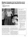
Bringing Computers into the Chemistry Lab at
SUNY at Cobleskill Inspires Students and Faculty
by Joe Nunes
Chemistry Laboratory Program
Agricultural and Technical College
Cobleskill, NY
Walton A. Brown, President
SUNY at Cobleskill "The social impact of the computer became increasingly apparent during the decade of the seventies. To respond constructively to the resultant changes in our
society, colleges are improving quality
and efficiency by adopting computer resources and techniques to instruction.
"One such application is that of adopting
the Tektronix graphics computing systems
to instruction in chemistry. Specific techniques and software were developed at
this college over the past five years. Students now experience computerized instrumentation as a complete data acquisition and-processing system. The application of what they learn to "real life laboratories" is readily apparent to them and
to their employers.
"The program of instruction developed
by Professor Nunes has resulted in:
Professor Joe Nunes, right, points out one of the equipment configurations for the Laboratory-Computer
Training Program in Chemistry to Walton A. Brown, president of Cobleskill College.
The chemistry program needed improvement. Pre-lab assignments to familiarize students with upcoming experiments were occupying valuable instructor time. Motivating
students to accurately collect data, analyze
it and graph it was wearying. Who wants to
fit experimental points to theoretical equations which consistently require multiple
tedious calculations? And, the graduates
were expected to have some computer skills
for data acquisition and analysis.
Computers, of course, were the solution. But
which system and how? In a small college
which has a very limited budget, the money
has hardly been adequate to purchase traditional equipment and supplies let alone expensive new equipment. An informal study
begun in 1977 resolved these questions with
the first delivery of Tektronix 4050 Graphics
Systems in 1980.
• More efficient use of faculty
time,
• Improved student motivation,
• Establishment of more meaningful relationships between
"background courses" such as
Calculus and Statistics, and
laboratory applications in
chemistry,
• The ability in every student to
program laboratory work in
BASIC.
"This article describes a significant development in science education, and particularly in the preparation of industrial and
research laboratory technicians. "
At the Agricultural and Technical College
at Cobleskill, the Chemistry Laboratory program equips future science technicians for
the working world, or prepares them for further degree work. The students come from
a variety of technical curriculums available
at this accredited two-year college of the
State University of New York. Training stuTekniques
6
Vol. 6 No.4
,r
dents in relevant occupational skills for job
placement, competitive salaries, job advancement, or for advanced studies is critical, and
/ " the current Laboratory-Computer Training
Program in Chemistry is doing the job.
Twelve 4051 systems and a variety of peripherals give students "hands-on" computer
experience in a laboratory setting. Computerized pre-lab assignments have freed the instructors for more individual student assistance, and, surprisingly, have effected more
actual lab time for studen'ts who desire it. A
significant reaction has been the number of
students who indicated that they now understand how "pure" math learned in other
courses applied to their science courses. Wetbench work for computer-related experiments is done more carefully and the students strive for precision and accuracy in
their data. From written and computerized
evaluations, it is evident that students have
a better understanding of the laboratory activities which are computer related.
It readily became apparent that the training
conditions needed improvement. The general
chemistry laboratory sections had enrollments of 20-24 students and only seven 4051
systems were available. Thus, an average of
three students worked with one system during the formally scheduled lab session. Observation clearly demonstrated that three students per 4051 system was not desirable,
which was borne out in a subsequent written survey of the students. Students who
worked alone or part of the time in pairs on
a graphics system showed the highest degree
of enthusiasm, interest 1md success.
To improve and update the training conditions, a second grant proposal was submitted to the same granting agency. This second
grant (1981-82) funded five 32K 4051s, four
with data communications interfaces, a 4611
hard copy unit, seven 4952 joysticks, two
4662 eight-pen plotters, two 4907 File Managers, and a Datagram Concentrator for interfacing with the host computer, a Burroughs 6810, in the college computer center.
Equipment Acquisition
But to get to this point from 1977 took some
groundwork. After extended research including contact with former Cobleskill graduates,
employers of our graduates, and Science Advisory Board members, we found the most
beneficial use of computers by the students
in the chemistry laboratory program would
be direct input of laboratory data into a computer located in the same lab or at least very
close. From a functional, practical and cost
(immediate as well as continuing) point of
view, microcomputers appeared to be the
best choice.
Three popular personal microcomputers were
closely examined but these systems didn't
provide the graphics capabilities which were
important to the improvement of the chemistry program. Also, these systems were not
being used by employers of our graduates.
In fact, the computer systems most commonly encountered in the work places investigated were Tektronix graphics terminals or
Tektronix 4050 Series stand-alone graphics
computing systems.
The grant proposals submitted under the Vocational Educational Act (VEA) administered by the New York State Department of
Education funded seven 32K 4051 Graphics
Systems, four with the data communications
interface, two 4631 hard copy units, two 4662
digital plotters, a 4956 graphics tablet, two
4641 line printers, two ROM expanders with
a variety of ROM packs, the complete Tektronix PLOT 50 software library, a TransEra
AID Converter with a real time clock, and
some startup supplies, all delivered in late
1980.
Tekniques
Vol. 6 No.4
The increased number of 4051 systems greatly improved the training conditions in the
program for the 1982 Spring semester. This
was clearly evident from observation, from
informal student comments, and from a second student survey.
Equipment Configuration
Equipment is stationed in three rooms with
different configurations; however, this arrangement is flexible since all equipment
items are portable. Two configurations provide for the highest volume usage by students
while the third configuration is used for direct interfacing with instruments in the analytical laboratories.
Eight 4051 graphics systems and two hard
copy units are in a room adjoining the general chemistry laboratory. This configuration
accommodates up to 16 students working in
pairs. The immediate proximity to the lab
makes it highly favored by the students
throughout the formally scheduled lab session. At peak times, the overflow is handled
by the systems located close by.
A second configuration of three 4051 systems, line printers, hard copy unit, file managers, and the tablet accommodates student
use when peripheral equipment other than
hard copy units are required for completing
the laboratory activities. This area is also
used by the faculty for software design and
development. Located in this area is the Datagram Concentrator which allows up to 16
systems to be interfaced into one port of the
college computer center's Burroughs 6810.
Cable connections are available from the first
configuration enabling those systems to be
interfaced with the Datagram Concentrator.
The instrumentation configuration located
in either of the two analytical laboratories
includes a 4051 system, a plotter, and a TransEra AID converter with a real time clock.
This configuration can be interfaced with a
variety of instruments used by students in the
analytical courses.
Hardware and Software Applications
The Tektronix PLOT 50 System Software Tutorial has proven to be an excellent handson learning experience for students. No prior
computer experience is required. With good
training conditions, students become quite
'adept in working with the 4051 and in learning fundamental BASIC statements and
graphics commands unique to the system. As
the semester progresses, students are gradual-
Eight 4051 Graphics Systems in close proximity to the general chemistry laboratory provide science
technician students with relevant training.
7
and "Introduction to Graphic Programming
in BASIC," students with no computer experience learned to write programs on their
own with little difficulty. The high resolution graphics of the systems are consistent
with the intent of the training program, and
similar to the kind of data analysis which is
expected of our science technician graduates
by prospective employers.
Future
In the analytical laboratory, the 4051 system can be interfaced with a variety of instruments using the
TransEra AID converter.
ly introduced into the use of the peripheral
devices.
Software has been developed by the faculty
for some of the laboratory experiments used
in the general chemistry courses. A typical
program will verify the pre-lab assignment,
request student input of experimental data,
and require student experimental data analyses. A package of modules for a semester
in a course can usually be contained on one
or two tapes.
Because the students may use the tapes other
than at scheduled lab sessions, often they will
verify their pre-lab assignment prior to their
scheduled lab, thus, providing themselves
with more time for wet-bench work, for data
analysis, for repeating part or all of the experiment, and for lab report completion.
All of the laboratory software modules have
been student-tested and work well. Programs
developed for the experiments include the
atomic spectrum of hydrogen, geometrical
structure of molecules, vapor pressure and
heat of vaporization of liquids, determination of the equilibrium constant for a chemical reaction, and many others. The Simple
Regressions program from the Tektronix Statistics Library is accessed by several of the
programs for analyzing data. The program
will fit eight functions to data of the form
(X,Y).
Tektronix equipment in the analytical laboratories is used exclusively by students in Instrumental Analysis, a second year course for
science majors. The Tektronix 4051 is interfaced with an analytical instrument in two
phases to provide students with a better understanding of how the final results are
obtained.
As the first phase the students perform the
experiment, manually measuring and recording all the data and then write their own program in BASIC to perform the analysis.
This, we find, requires a more thorough understanding of the algorithm for the results
than does a hand calculation. It also establishes the role of the 4051 in an integrated
computerized system.
In the second phase the 4051 is interfaced directly with the instrument. A program running on the 4051 enables students to collect
and manipulate data. This procedure provides the students with valuable experience
for future jobs; they now recognize the computerized instrumentation as a complete data
acquisition and processing system while using
equipment representative of what they will
encounter in future laboratory work.
Results
While still too early to determine the long
range benefits, discussion with recent graduates who are now employed indicate they
are often expected to write their own programs for data analysis. These visiting alumni also frequently encounter Tektronix equipment whenever graphics is essential in the
work. In a recent survey by the College Placement Office, two 1982 science technician
graduates reported starting salaries of approximately $18,000.
The Tektronix equipment has met all expectations. Despite the relatively high volume
use by inexperienced students as well as experienced ones, the equipment has proven to
be reliable and durable. For the few occasions
needed, Tektronix service has been prompt
and efficient. The manuals are clear, concise
and easy to follow. Using the two manuals,
"Introduction to Programming in BASIC"
Construction of new science facilities includes a scientific graphics computing laboratory. The graphics lab will contain the
equipment described in the second configuration and some future acquisitions. Centrally located to all science labs, this lab will
serve as a distribution center for a localized
network of computing systems for scientific
applications, and will serve as the intermediate link to the college mainframe computer. Interest and support indicate expanded
use of computerized systems for other science
labs.
The enthusiastic student response to the
Chemistry Laboratory Computer Training
Program coupled with the very positive results has provided the initiative for a separate course on computer programming emphasizing graphics in science applications.
We anticipate an increase in student enroll- 1/''')1)
ment as curriculums become more visible to '< /
prospective students. This, of course, would
have an overall effect on the enrollment
trends in the Chemistry Laboratory Training program.
The bottom line at Cobleskill has always
been on how well the college has prepared
its students for their future life goals after
graduation. Without question, bringing Tektronix equipment into the Chemistry Laboratory Computer Training program has definitely stimulated the entire chemistry instructional program and is making a valuable
contribution to the attainment of that college goal. §J
Editor's Note: Joe Nunes' original manuscript fully documents his grant procurements, and describes all aspects of the equipment's use. Unfortunately, space restrictions prevented TEKniques
from printing the entire report including details
which would be helpfUl to others interested in updating their educational program. Joe would be
happy to send a copy of his complete documentation to those interested. He may be contacted by
writing or calling:
Joe Nunes
Suny Cobleskill Agricultural and Technical College
Cobleskill, NY 12043
TEKniques is grateful to Professor Nunes for
taking the time to describe his program and to Bill ","=,-1
Longobardi, Tektronix Sales Engineer at Albany,
NY, for bringing Joe and his work to our
attention.
Tekniques
8
Vol. 6 No.4
Excerpts from a pre-lab assignment
A laboratory simulation program used during acid-base experiments allows students to
choose experimental variables and observe
the effects of changing these variables. An
added feature simulates a buret and Erlenmeyer flask with volume changes in both as
the reagent is dispensed by variable volume
amounts or by drops. The students prefer
plotter output since it highlights the titration
curve with different colors.
:t'n
***
APL.OT OF !?H '/s IJOLUME OF BASE ADDED
'.
~
,~
itt
49.99
~~~T T~E G~t~~A~~O~HO~E~~~~5 U~~US~ g~ 1r~~E MA~gEo
STRONG BASE! II GROUP IA METAL HI'DRDXI[)E),
(t>ROP} IHCREI1EtnS. THEN THE pH US VOLUME OF BASE
AC·DED WILL BE PLOTTED.
[~PUT
STROHG ACID IH 'FLASK'
ITS FORPIULA
HCL
STROHGBASE IN 'BURET'
TITRATEDV (fll) AFTERU.l4 i'lL HAUE BEEN AODEIl UNTIL.
AL.I. THE 8ASE HAS BEEH AIlIlEIl.
THERE ARE 29.08 DROPS IN 1.880 i'lL.
M~RR~~.,e~L. ~~~ ~ 0O~O B~O ~~:~~~ ?f'lL.
CHOOSE (ML.) IHCREHEHTS(O.!5TO'l5).!5
****
IHPUTITSFORI'IULR
HADH
IHPUTBASE COHCEHTRATIOH (4 Sli:i FIG PLEA8E)
IHPUTBASEUOLUKE (KA!{. !50.00f'lL>
49.98
0.131i!5
""'~'HCL
_n·)L
24.8~
(fig lb)
-1' ''\- -
f ~::1
STRONG ACID-STRONG BASE TITR/.TION CURVE
THEEQUIVIlLEHCEPOINTREQUIRESIBDROPS,
"
"
HUMBER OF t>ROPS TO RELEASEi' (I TO 21\1)1111
Ll£T DATA?O'ESOR NO)
TO CONTUIUE, PRESS 'RETURN'
>
TO COIHIHUE, PRESS'RETURN'
REAIlYTOTITRATE?(YESORHO)VES
TOCOHTIHUE, PREBS'RETURN'
(fig la)
'"
49.98
FOR THE IHTERUAL. OF20.S4 i'lL.
PL.USoRI'IIHUse.!5ML., USE (DROPS).
NADH
t***
i~~Hf ~gIg 6g~&~MT'A~~~H5~~eil~L~IG2~~~~SE) 8.1145
tt:r:t
*U
FDREFFICIEHCV, TITRATEBV (Ml.) UP TO 20.34 f'lL..
RECDI'II'IEHDEDIHCREMEHTSAREO.I!II1L.UPTO!5ML..
9.1365
i'!OLAR
THE BASE IoIILL BE ADDED B\,(ML) IHCREI1EHTSORBV
-un
SELECT UOj.Uf'lE DELIUERV MODE FORTITUTIOH
THEI,IOLUf'lEIHKLOFBASEHEEDEDFDRTHEEQUIUIIILEflCE
POIHT IS 20.04.
STROHG MOHOPROTIC ACID) WITH B.1365 M HAOH
12
0.1365
2~.G.!1.. • ~g5eR
II
\8 ____________________________________________________ _
,
,
~
§
7
~
:a~
5
4
,,
,,
,,
ONEDROPj6pHUNITCHANGE
___E_~U!_Vjl~_E!l_C_E_!_~!l_T__ >
1+___________ _
_______________________________________
·.f--"~'1~.-,,~'-,2~.-,2~'-..~.-..~,~.~.--.~,~'"
VOLUME Of BASE ADDED IN ML.
(fig lc)
(fig ld)
Methods for teaching computerized analysis
Interfacing the Tektronix 4051 with an analytical instrument in two phases provides
students with a better understanding of how
the final results are obtained. A gas chromatograph was selected as the first instrument for this purpose.
A typical student experiment with this instrument is determining the percent composition
of a mixture of volatile liquids. A mixture
of known composition is injected into the
chromatograph. The instrument separates
the components and generates an analog
signal which is recorded with a strip chart
recorder.
First, the students perform the above experiment, manually measuring and recording all
data from the chromatogram. They then
write their own program in BASIC to perform the response factor and percent composition calculations. Results from a student
program are shown below.
students to collect and manipulate data with
the User-Definable Keys using a 4952 Joystick to interact with the data, defining peaks
of interest and expanding portions of the
chromatogram for closer examination. Output is directed to the 4662 Plotter, shown
below.
In the second phase, the students interface
the Tektronix 4051 directly with the gas chromatograph using a TransEra 652 AID Converter. A program written in BASIC allows
Additional software will interface other departmental instruments such as infrared and
ultraviolet spectrophotometers with the Tektronix equipment.
G'::'~
~E~!'
Each peak in the chromatogram corresponds
to a component in the mixture; the area
under a peak is proportional to the amount
of that component. Each component has a
unique proportionality constant called a
response factor which can be calculated from
the chromatogram of the known mixture.
The unknown mixture is then injected, peak
areas are measured, proportionality constants are applied to the peak areas, and the
percent composition is calculated. This procedure requires a lot of measurements and
manual data transfers. It is, of course, very
time consuming and error prone, especially
when the calculations are done by hand.
JOE! SpragUE! -
standard m \ )(ture of a I coho I a
----
,
3
4
---- PHUL YI~ WORDEH
APEA
---'328
389
312
325
RESPONSE FHCTOR
--------------£1.943
1.eea
e.SEl2
0.835
UHIOmL.!H ''UxTURE
PEAK
---1
2
~
AREA
---164
596
211
254
,4
PEAK
---1
2
3
4
TR
----0.71
----0.40
1.06
1.35
2.56
2.25
AIr peal<
T'R
0.75
1.05
HEIGHT
AREA
------------- 0.824279
1.0000
0.6641
0.5126
0.2214
IIIiI Identified at
Tekniques
Vol. 6 No.4
CHROfolATOGRAPHY - RESPOHSE FACTOPS
S T4~1['HIi.D MIXTURE
9
1.00000103
0.956054
0.903145
103.31
mlnut.ellil.
ADJUSTED AREA
------------195
596
2153
304
PERCEIH
C01-1PO~
14, '3
43.9
\9.4
2.2.4
I T I Ol~
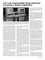
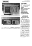
4110 Local Programmability Brings Distributed
Processing to Graphics Applications
..~)~
'-,
"
/'
ly, to access the terminal's graphic and alphanumeric features, and to control all peripherals (plotters, printers, graphics tablets,
mass storage devices) connected to the
terminal.
Local Programmability relies on a new 8087
numeric coprocessor and ROM/RAM board
as well as the 4110 terminal's standard 8086
processor. These hardware additions speed
floating-point computations and enhance the
processing of such applications as technical
data analysis. Existing 4110 Series terminals
are easily upgraded through Field Kits to
4110A terminals.
The 4110 Series of Tektronix terminals enhanced your applications with low-cost, high-quality graphics.
LOCAL PROGRAMMABILITY adds computing power allowing you to locally develop, debug and
run programs on the 4110A terminals. All of the sophisticated graphics features of these raster scan
and DVST terminals are directly accessible.
Mapping, structural design, circuit board layout - the very nature of interactive graphic
applications dictates that much of the activity
takes place at the user's workstation, not
within the host computer. But, ironically, the
workstation terminal must depend on the
remote host to drive this activity. Picture
data must be transferred back and forth
before being displayed, consuming precious
host processing time while introducing inevitable delays at the terminal for turnaround. And, should the communications
link fail, the terminal loses all graphics capabilities. It makes sense, therefore, to allow
an intelligent terminal to process the graphics
locally, leaving the host free to use its power
for number crunching, data base management, or supporting more terminals.
The 4100 Series Local Programmability,
recently introduced by Tektronix, distributes
the processing by allowing the 4110A Series
of Tektronix terminals to run applications
programs locally. Although these intelligent
terminals by themselves were able to relieve
the host of retransmitting entire sequences
of graphic data or commands, * complete
local control or stand-alone use wasn't possible. Local Programmability closes this gap.
A Typical Application
Although some applications will continue to
require a host for its computational power
or large data base storage, using Local Programmability the preprocessing or postprocessing of the graphics data can be assigned to the 4110A terminal. For example,
consider a finite element analysis application
using a 4110A terminal with Local
Programmability.
By running the program locally, without connection to the host, you can do all the preprocessing for the application at the 4110A
terminal. First, you generate the model of
a structure using the keyboard thumbwheels
or graphics tablet. Local Programmability
provides control of the terminal's intelligence
allowing you to reposition, rotate and scale
the displayed model, make changes, or even
draw the structure on a plotter. Once satisfied with the model displayed on the screen,
you log on and transmit the model description to the host qomputer for analysis. The
analysis data from the host is then transmitted to the 411OA. After logging off the host,
you continue the postprocessing at the 4110A
terminal. In this case, the host system was
needed to analyze the finite element model,
but the locally programmed 4110A terminal
did everything else.
Many application programs - mapping,
CAD, CAM, curve and spline fitting,
graphing and linear regressions - can run
on the 4110A graphics terminal without any
host support. Digitizing a map on a graphics
tablet, for example, can be done locally on
the 4110A terminal without the costs and line
delays of communicating with a host system.
The Tools
A powerful package of software, 4100 Local
Programmability supplies all the elements
necessary to develop and run programs local-
The 411OPOI Local Programmability package includes a FORTRAN-86 compiler, utility programs, and a library of Low-Level
Terminal Interface (LTI) subroutines, all implemented with an industry-standard operating system, the CP/M-86. A local version
of the PLOT 10 Interactive Graphics Library
(IGL) may be included. For those programmers who need assembler support, Digital
Research's ASM-86 assembler or Intel's
ASM86 assembler are also available.
Designed specifically for the 8086 microprocessor and 8087 coprocessor, FORTRAN86 is a superset of the ANSI FORTRAN-77
subset. FORTRAN-86 allows easier and
quicker program development, easier manipulation of large amounts of data, and easier
understood and maintained programs. But
compatibility has been maintained and most
earlier FORTRAN programs will run as is
with possible minor input/output modification, thus protecting your current software.
FORTRAN-86 programs can directly output
character data to the terminal or can call the
LTI routines to access all the sophisticated
4110A Series graphics features. This library of
routines provides a quick path to the terminal's firmware through FORTRAN-callable
subroutines with easy-to-remember names.
Or, to save time and money, you can take
advantage of the local PLOT 10 IGL. A core
standard set of routines for graphics and text
interaction, IGL acts as an interface between
your application program and the L TI
subroutines.
The powerful set of routines of local PLOT
10 IGL are compatible with the host version
of PLOT 10 IGL. Thus, you may run locally
on the 4110 terminal your existing host programs that use IGL. You simply download
Tekniques
10
Vol. 6 No.4
your program source file. It is then compiled
and linked to Local IGL.
The CP/M-86 operating system allocates
/ , system resources and provides program development aids and separate user libraries.
In addition Tektronix has provided additional utilities which enhance the operating
system's usability.
For those users who need the unique capabilities of an assembler and do not require
direct interfacing with 4110A Firmware,
Local Programmability provides support for
the Digital Research ASM-86 and the Intel
ASM86. The Digital Research assembler is
small and fast and provides easy access to
low level CP/M-86 operating system services.
However, the ASM -86 output code cannot
be easily linked with FORTRAN programs.
The Intel ASM86 assembler output code is
completely ~ompatible with FORTRAN
through the linker-editor.
The Process
Using the tools provided by Local Programmability, you can create and edit your source
program in FORTRAN-86 or ASM86 macroassembly language. This source file is then
compiled or assembled into 8086 executable
object code.
A linker program - LINK86 - merges all
of the 8086 object modules comprising your
program into one module that can be executed by the 4110A terminal. For instance,
all LTI and IGL subroutines are stored on
disks in the form of object code. If your
source program calls any of these subroutines, the LINK86 program extracts the
called modules from the libraries. LINK86
resolves external references (e.g., any address
field that refers to a location in a different
object module) and generates a link map and
error list.
Tekniques
Vol. 6 No.4
The individual linked program modules are
stored in a disk file and can be run locally
on a 4110A terminal. The size of the program
is limited only by the amount of available
local memory.
You can also create and maintain your own
library of object modules. A utility program
provided by Local Programmability will join
a series of object modules into a library, will
add and delete library modules, and will generate a listing of the modules and public symbols in a library file.
The power, flexibility and diverse strengths
of the 4110A Series terminals provide the
hardware tools for a wide range of graphic applications; now Local Programmability offers the solution to slow data communication lines. No longer are you relegated to impatient waiting for even the simplest tasks
and functions. Local Programmability gets
the job done quickly by putting the graphic
computing power where it belongs - at the
fingertips of the user.
Contact your local Tektronix Sales Engineer
for more information on how Local Programmability can help you with your
application . ./!):J
* TEKniques
Vol. 6 No. 3 discussed segments,
fonts, programmable keys and other unique
strengths of the 4110 Series of color and monochrome raster scan and DVST terminals.
11
4052 Helps Reveal Secrets of Antarctica Data
~.
,
)1'
'-.-
-'"
1655 individual analyses for a lO8-meter
South Pole ice core and 598 analyses from
a 47-meter Vostok core.
Samples Interpreted
With the help of the 4052 Desktop Computer, Dr. Zeller is extracting a picture from the
ice sample data. He reflected, "We are able
to connect with our central computer, but
as far as we're concerned, the 4052 is a mainframe and it's been very satisfactory. Right
now we use it primarily for data analysis. We
routinely apply polynomial regressions, linear
regressions and various smoothing functions
from your Statistics and Mathematics packages. We've also modified some of the programs and have cooked up some ourselves."
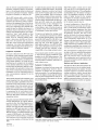
Making annual treks to the Antarctic continent during its summer, Dr. Giesela Dreschhoff (left) and
Dr. Edward Zeller collect ice core samples and mineral resource data which are later analyzed at the
University of Kansas on the Tektronix 4052 Graphics System.
by Patricia Kelley
TEKniques Staff
"Before I got this equipment I knew I would
be dealing with a large number of data points.
While raster scan has its place, without the
storage tube I couldn't get the needed resolution to display all the data points and would
have to look at my graph piecemeal. That
would make it much more difficult. The Thktronix 4052 has an enormous advantage; I
don't think I could find anything better."
The speaker is Dr. Edward Zeller, professor
of geology at the University of Kansas. He is
part of a team of scientists engaged in longterm studies aimed at improving our understanding of the sun.
The Changing Sun Captured in Ice
Over the past centuries, solar activity (flares,
sunspots, storms) has been pretty well documented, and periods of maximum and minimum activity identified. Captured within the
frozen terrain of Antarctica, a series of physical clues not available anywhere else seems
to echo the visual records informing of the
sun's behavior. Nitrate concentrations within the ice correlate positively with some of
the known features of the solar activity record.
Pursuing these clues, since 1975 and each
year thereafter Dr. Zeller has been visiting
Antarctica during the astral summer collecting ice core samples from various sites. In
this "laboratory" a layer of snow is developed each season. Since these layers can be
counted like tree rings, the amount of snow
that falls each year is predictable over time.
Dr. Zeller and his colleagues collect the
samples, from areas known as South Pole
Station and Vostok Station, by digging pits
and chiseling out plates of snow or by drilling ice cores. The samples are packed in sections in plastic tubes and sent back to the
United States in refrigerated ships, and ultimately flown to Virginia Polytechnic Institute in Blacksburg.
There, the sections are carefully calculated
for density and the average annual accumulation rate of snow and water. Professor Bruce
Parker of the Department of Biology then
chemically analyzes the cores for nitrate
using ultraviolet spectrophotometric
measurement.
The resulting data are sent to Dr. Zeller at
the University of Kansas for processing. In
the examples discussed here, samples covering approximately 1200 years were taken 12
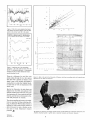
Figure 1 shows the raw data from the two
ice core samples plotted on the 4662 Plotter,
and Figure 2 shows the same data smoothed.
Comparing the data from the two Antarctica locations, the raw data in Figure 1 and
the smoothed curves in Figure 2, reveals the
general similarity between the two. And
reading the graphs from left to right, the
correlation between the nitrate deposits and
the observed solar activity periods is clearly
shown:
present to 1850
1820-1790
1715-1645
1510-1400
1280-1120
-
Modern Maximum
unnamed short minimum
Maunder Minimum
Sporer Minimum
Medieval Maximum
Where the nitrate levels are low, there has
been less sunspot activity; where the nitrates
are high, the solar activity has been high.
"We also do Fourier transform to determine
the main frequencies present in the total signal," observed Dr. Zeller. "We have found
the power spectra in the samples from the ice
cores to be very similar for both locations."
By establishing the correlation between nitrate
levels in the ice with known solar activity and
cycles, Dr. Zeller and his colleagues can extend the correlation to get a longer backward
look at solar activity from ice samples deposited before recorded solar history.
Mineral Resources
A second program in which Dr. Zeller is involved also employs the 4052 Graphics System. He and Dr. Giesela Dreschhoff have
been working since 1976 to determine if there ":-7
is a resource potential for uranium and thorium on the Antarctic continent.
Tekniques
Vol. 6 No.4
3,2
2.4
ATh
1.6
.0,8
Figure 1. Plot of ice core samples from South
Pole Station and Vostok Station with 1655 data
points in the former and 598 in the latter.
0'
0.S
1.6
2.4
3.2
AU
COMPARISON OF SOUTH POLE AND VOSTOK SMOOTHED NITRATE
CURVES WITH ATMOSPHERIC CARBON-14, (ADAPTED FROM EDDY,
1977 AND CORRECTED FOR EARTH MAGNETIC FIELD CHANGES)
48
SOUTH POLE
....
"
J
-s
g
... 18
0
..,.u 10
-
L
<J::
-,
'.--r----1---t----j--1980
1700
1500
1300
1180
.
8
18
28
30
"Ie
$8
60
_+-_
900
\'tARS
Figure 2. Applying one of the smoothing
functions - the cubic spline program from the
PLOT 50 Mathematics package - to incremental
averages from the raw data obtained the 10-year
interval smoothed curves,
Flying in a helicopter low and slow over
peaks poking through the ice, they capture
their data with a gamma ray detector. The
signal is sent to the recorder and logged in
analog form on a strip chart (digital recorders don't like to work in temperatures well
below zero).
~
.
Figure 3. Back at the lab at the University of Kansas, strip chart recordings taken in Antarctica are
digitized into the 4052 and analyzed.
Back at the University, the strip charts are
digitized into the 4052 and analyzed. The
analysis will show the total count, the count
from potassium 40, from uranium and from
thorium, and the ratios of potassium to thorium and potassium to uranium.
......
~
The nitrate sampling and resource investigation are on-going. Sorting, analyzing, plotting, the Tektronix 4052 Graphics System is
helping Dr. Zeller wade through volumes of
data in his quest to open a window on the
sun and to reveal Antarctica's resource
potential. ./!J)
The gamma ray detector and analog recorder shown will be loaded into a helicopter and flown over
Antarctic mountain peaks to gather data on potential uranium and thorium resources.
Tekniques
Vol. 6 No.4
13
PLOT 50 2-D Drafting New Release Offers
Increased Performance for Automated Drafting
A
.
\...
Support for the Extended Memory File Manager, l the 4909 Multi-User File Manager and
additional D and E size plotters has been included in the recent release of PLOT 50 2-D
Drafting;2 new functions and increased communication add to its performance. All at no
additional cost.
PLOT 50 2-D Drafting enhancements offer
users whose 4050 Graphics System is equipped
with the Extended Memory unit several options for optimizing their drafting tasks. 2-D
Drafting function overlays - some or all may be stored in Extended Memory. Thus,
a medium sized drawing could fit within Extended Memory along with the most used
functions to provide rapid interaction. Or,
a user with a huge drawing could use the disk
for drawing space and all of Extended
Memory for function overlays. Conversely,
a designer may wish to use all of Extended
Memory for drawing space and call the overlays from disk. Which option is best depends
on the application and, therefore the user's
choice.
Full 4909 Multi-User File Manager support 3
supplies the capacity for the PLOT 50 2-D
drafting user to take advantage of the hard
disk unit. File management is automatically
provided; the PLOT 50 2-D Drafting user simply responds to prompts.
PLOT 50 2-D Drafting has always included
plot drivers for CalComp and Tektronix plotters. Now Hewlett-Packard and Benson D
and E (AI and AO) size plotters are accommodated, directly through the software, or
indirectly through TransEra ROM packs.
Users with the Thktronix 4054A Series Graphics Systems will find item selection and crosshatching. speeded since the new release of
PLOT 50 2-D Drafting takes advantage of
the "A" series capabilities. Enhancements
for drawing creation and communication expand the system's versatility and ease of use.
or Software Subscription Service will automatically be provided with the enhancements
in this release.
Your local Tektronix Sales Engineer can provide you with more information on automating with PLOT 50 2-D Drafting . ./!))
1. TEKniques Vol. 6 No.3 outlined the capabilities of the Tektronix Extended Memory
File Manager.
2. TEKniques Vol. 6 No.3 described this standalone, two-dimensional drafting system for
electrical, mechanical and other engineering
disciplines.
3. See the accompanying article "PLOT 50
Software Supports 4909 Hard Disk" in this
issue.
The new release of PLOT 50 2-D Drafting
is offered at the original price. Existing
PLOT 50 2-D Drafting users under warranty
PLOT 50 Software Supports 4909 Hard Disk
The success of Tektronix PLOT 50 2-D Drafting, Interactive Digitizing and Picture Composition application packages* in streamlining and speeding drafting, mapping and
drawing tasks causes a natural increase in
users or data or both. To accommodate this
growth, Tektronix has expanded these PLOT
50 software packages to offer users the advantages of the Tektronix 4909 Multi-User
File Manager.
Full support of the 4909 hard disk unit by
these packages permits up to 10 simultaneous
users, and the 4909's capacity up to 768
megabytes provides the large local storage required for the data intensive applications. By
sharing a 4909 unit, users achieve more value
per byte of storage and solve the transportation problem for those who rely on the
same data. The large capacity gives the user one or many - a single source for storage.
Program files and data can be stored and
loaded quickly and easily. Passwords and access codes give users security features to control their files' accessability.
to the 4909 version is painless. Functionally, the 4909-based software looks and acts
similar to the 4907 versions. Users aren't required to re-Iearn a new system, just some
minor terminology. Operationally, the performance of almost all operations is improved by the 4909.
PLOT 50 2-D Drafting, Interactive Digitizing and Picture Composition automate sizeable tasks. The 4909 Multi-User File Manager strengthens the process as the number of
users or amount of data increase.
Your local Tektronix Sales Engineer can provide more information on PLOT 50 software
support of the 4909's convenient, economical, multi-user mass storage . ./!))
* TEKniques Vol. 6 No.3, Vol. 5 No.3 and Vol.
5 No.1 profiled the characteristics of these three
packages.
For those applications which have outgrown
the single user 4907 File Manager converting
14
Tekniques
Vol. 6 No.4
\\1
.y'
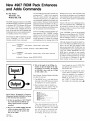
New 4907 ROM Pack Enhances
and Adds Commands
by Pat Franz
Tektronix, Inc.
Wilsonville, OR
The BASIC language extensions of the 4052A
and 4054A Desktop Computers necessitated
a redesigned 4907 File Manager ROM pack
to take care of such features as multicharacter variable names, comment tails and so
forth. At the same time, the File Manager disk
formatting function was streamlined and error handling routines were included.
Two choices of default parameters for the
CALL "FORMAT" or CALL "FFRMT"
functions simplify these commands:
The new ROM pack provides a default master password of " " (null) if it isn't specified.
Since the volume-number and number-ofvolumes must always be 1,1 on a 4907, these
are automatically supplied in the default command versions. Directory block allocation
parameters (chains) will default to 10,10,1,1,1.
This allocates ample directory space for first
and second level libraries and sufficient space
for less common lower level libraries.
Three error handling commands facilitate program operation. CALL "ONERR" transfers
control to a user-written routine when a File
Manager error occurs. This circumvents the
normal procedure of halting the program
and displaying the error message when a File
"FORMAT"
.
CALL "FFRMT" ,umt-number, volume-name, owner-name
(password, volume#, #Volumes, chains DEFAULTED)
or
"FORMAT"
.
CALL "FFRMT" ,umt-number, volume-name, owner-name, password
(volume#, #Volumes, chains DEFAULTED)
Input/
+
(Output) ..
3) Why is the length of the STRing of a
number one plus the length of the original number? For instance, the LENgth
of STR(400) is four, while the LENgth
of STR (-400) is five.
Steve Duncan, Technical Support Specialist
provided the answers:
1) The BREAK key is a very high priority
interrupt in the 4050 Series and cannot
be masked by any system operation.
2) Data statements may be implicity selected by using a line number with the
RESTORE command. For example:
100 INIT
110 DIM XIS)
David Walcutt, Propagation & Frequency
Management Specialist with Radio Free Europe
in New York has three questions:
1) Is there an equivalent of SET NOKEY
that would disable the BREAK key
during critical periods of program
execution?
.-- _7
2) How do you establish multiple data files
within a program using DATA statements so that only the specific data
file can be called?
:~~
140
160
160
170
180
190
200
210
8m HU'~0
DATA 11.12.13.14.15
DATA 16.17.18.19.20
RESTORE 140
READ X
REM, X CONTAINS 11.12.13.14.16
RESTORE 120
READ X
REM, X CONTAINS 1.2.3.4.5
Thus, data statements do not have to
be read in sequence, and the array can
be treated as a "data file." Or, perhaps
you wish X-array to contain the numbers of tape data files on which you
are working. In this case, you could
Tekniques
Vol. 6 No.4
15
Manager error occurs. This command would
prove useful in checking to see if a peripheral
was connected, if a disk was inserted in a drive,
or if other similar operator responsibilities
were carried out.
As part of the user's error-handling subroutine, a new command CALL "DSKERR" can
be included to retrieve the error code and
message, storing it in a target string variable
for further processing.
CALL "OFFERR" turns off the special File
Manager error handling set with "ONERR"
and returns error handling back to the normal File Manager routine, i.e., halting the
program and displaying the error message.
Although designed to handle the added features of the 4052A and 4054A Series computers, the new 4907 File Manager ROM
pack can also benefit 4052/54-4907 users. An
existing ROM pack may be upgraded through
a kit, part number 040-1091-00. The new
ROM pack is order able by part number
020-0279-01. Both of these may be obtained
by calling Central Parts Ordering. See page
25 in this issue of TEKniques for the telephone number serving your area . .!;jD
loop through the array by FIND XCI)
and perform the operation on the
desired data file.
3) The 4050 System automatically inserts
a space before a number to separate
values for readability. For example, if
you were to print the above array, i.e.,
PRINT X, the result is " 1 23 4 5",
not" 12345". It is the STR function
that supplies the separating space. J:jD
Crisp Images, Vibrant Colors
Distinguish New Color Copier
The transition from monochrome to color
in computer graphics is as natural as the transition from alphanumerics to graphics. Color
on the screen of a computer graphics display
communicates more information, more quickly, and more effectively. It is only logical,
therefore, that color graphics terminals are
rapidly entering a variety of areas from business management and technical data analysis
to cartography and computer-aided design.
But high-resolution color graphics are of
limited use if they can't be taken off the
screen and put into the hands of colleagues
or published in reports. Information sharing is a key factor in any application and to
share information on the screen of the terminal, it needs to be seen by others. Thus,
to achieve the full benefit of color, there is
as much need for color graphics on paper as
on the display.
Answering the need for accurate, economical, timesaving copies is the new Tektronix
4691 Color Graphics Copier. High image
quality and vivid color at a low cost per copy
are its trademarks. The 4691 yields copies in
B (A3) as well as A (A4) size. And, it's easy
to operate.
Color Copies
Any application where color is essential will
find the 4691 Color Graphics Copier a valuable tool. Designers of integrated circuits or
printed circuit boards can copy their displays
without losing the detail depicted by color.
Layers of different material, overlapping
areas, errors and mechanically conflicting
areas, all distinctly portrayed in color on the
graphics terminal, can be readily duplicated
on the 4691.
Color copies from three-dimensional solid
object or stress pattern modeling on the
graphics terminal can go into the mechanical
engineer's report. Architects can hand their
clients a realistic color image of their designs.
Piping and wiring circuits within a building,
designated by different colors, can be hard
copied for further analysis away from the
graphics terminal.
Drawing attention to key points, or simply
providing an aesthetic picture, color is inherent in effective presentations. The 4691
can reproduce charts and graphs for management reports, preserving the colors used on
the original display.
Quality Copies
Crisp, clear graphics and smooth uniform
colors distinguish the copies of the 4691 Color
Graphics Copier. The excellent image produced by the 4691 is the result of its resolution and its color quality. When people speak
of resolution, they are commonly referring
to the total dot capability (or addressability) of the device, the accuracy of the dots and
lines it produces, and the resultant ability to
accurately reproduce fine patterns.
The 4691 Color Copier has the highest addressability - that is, more total dot capability - of any color copier available today.
The 4691 places 150 dots per inch in both
horizontal and vertical directions. This gives
the potential for a B-size image to have over
2400 by 1500 dots!
High addressability and accuracy in dot placements allow the 4691 to faithfully reproduce
fine screen patterns, thus simulating color
shading as an extension of the basic eight
colors.
These excellent image characteristics are produced by the 4691 's exclusive implementation
of on-demand ink jet technology. The true
bright colors and superb color saturation of
the 4691 are the result of a special match of
ink and paper. Inside the 4691, droplets from
the three primaries yellow, magenta, and cyan
mix to form red, green, and blue. True black
is supplied from a black ink cartridge, rather
than from a mixture of primaries that can
form an "off" color of black.
Flexible Format
Image size and format often need to be
tailored to the task being performed on the
graphics display. The 4691 makes images in
B or A size, with the choice of landscape or
portrait format. B size is often used for the
most complex drawings, with landscape orientation for the largest image size, showing as
much detail as can be portrayed on a large
screen. For example, geometric modeling displays are often copied and analyzed in the
large size. A 4691 B size copy of a wire-frame
model, say, of an automobile in landscape
format would provide the design team a hard
copy for scrutiny showing all the model's
details.
A size is often used for reports. Here portrait orientation would provide easy reading
in a notebook. The color reproduction of the
final design or graph copied in A size in a
portrait format could be inserted into the
engineering or management report.
Easy Operation
Relinquishing copy control to the program
frees the operator for other tasks. Up to 50
copies of an image may be selected with a
single command. Landscape and portrait image formats are also selectable under program control. And a status command in a
program can detect ink or paper supplies,
and the state of the copier: whether it's busy,
for example.
Paper handling by the 4691 is automatic,
with 50 cut sheets in the chosen size, vacuumpicked from the paper tray, and automatically stacked in the output tray. Copies come
out dry, with the image side down to "collate" the copies.
Individual snap-in, self-sealing ink cartridges
for each color avoid messy fingers and economize on total ink use. Depending on the density of the images, the large capacity 200 ml
cartridges may last for over 4000 copies. The
ink quantity is electrically monitored and only
the cartridge that is empty need be replaced.
Front panel lights signal when ink and paper
are low, or when service is required.
Compatible Configuration
A firmware option permits the 4691 Color
Copier to be plug-compatible with the 4113A
pedestal and desk configurations. It allows
4113A copy either push button from the
keyboard or under program control.
As a special feature, Plot 10 Easy Graphing
II and Local Programmability packages can
execute display patterning which adds as
many as 125 shades to the 4691 's basic eight
colors. Hard copy colors are automatically
matched to those on the screen.
Commands support image spooling to the
optional 4113A internal disk which means an
image file is created on disk that can be
recopied to the 4691. This permits work at
the terminal to continue virtually uninterrupted during the copy process.
The 4691 Color Graphics Copier is meant to
be shared. The multiplexing option connects
as many as four terminals at once to the
4691.
The high performance of the 4691 - in particular its ability to place 2400 by 1500 dots
in a B size image - makes it appropriate for
sharing as a host system resource. Host copy
means connecting the copier directly to the
mainframe processor instead of the terminal
which allows the 4691 to copy the host data
at its full resolution. Because it's connected
to the central data source, a host-connected
4691 can serve all the workstations in a
system. In future issues of TEKniques, we'll
be talking more about host interfacing. J:$J
Tekniques
16
Vol. 6 No.4
<;,l
So:>;"
::l
•
'" .E.
Z;;
o '"
.j>.
HeAD J.99 CURRENT ELEMENT-
INC-
(t1IL9
HSHS
n:
IDSt:REP
81 /09/ B~ . 14 . al . I..
LEV ~
LEV f...-.-
LEV ~
LEV 4....-LEV 5..--
.: :
.,
..... ...~:....... :. ....... .
.
.
...:
,
; ~...... ~........ :......... ......... ..
NO. NAME LEVE
t C:CtBS t
2 '::C1U2 1
3 DIEL 4
'I '::C1 U:3 1
5 R1t11
12
7 R1t14
9 R1t19
12
1 2
12
11 R1t1?
12
~
R183
! R185
18 Rf88
12 R1'15
1 2
1 2
1 2
13 CC288 1
1'1 CC118 1
15 R1t1SA 5 3
1~ R186B 5 3
17 EriCAP G
1! PDAG
1
eEl ReElS
1 e
19 R2t19
12
23 R2t1S
12
25 R2t12
5 3
22 R2E13
......
2~
-J
12
21 R26?
R204
2' CC2B:l
1 2
1 2
1
27 CC282 1
2Z CC210
1
29 R26SA 5 3
~O
R20eS 5
31 IC61
~
5 1
g2 CC2B9 :l 1
33 CC109 3 1
g~
ICn
35 IC63
~'C101
5 1
5 1
~
37 COriD G5
~Z
C201
5 1
1 4 5
39 R162 5 3
40 R201
1 2
41 TICKS G
42 R2fB
43 R110
4~
A one-to-one reproduction of the copy produced by the Tektronix 4691 Color Graphics Copier
demonstrates its clear graphics and vivid colors. The image was copied from a 4113A graphics display.
GRID-
1BO(MILS)
1
1
EPOXY 7
Tektronix GPIB Extender Stretches
the Data Link
by Gordon Gunderson
Tektronix, Inc.
Wilsonville, OR
Permitting GPIB communication over distances of 1650 feet (500 meters), the new Thktronix GPIB Extender puts the power of the
4909 Multi-User File Management System in
the hands of remote users. Tektronix 2-D
Drafting System users, for example, can employ the GPIB Extender to share a data base
on the 4909 hard disk even though their design stations reside in different rooms or even
different buildings. Tektronix GPIB test instruments linked as customized automated
test packages at detached locations through
a 4050 acting as a Controller could also share
a 4909's storage capacity through the Extender.
But the GPIB Extender is not limited to the
4909 hard disk unit. It is compatible with any
standard GPIB interface. Any workable localonly GPIB configuration may substitute the
extenders in a portion of the configuration
that may need to be remote. For example, a
Tektronix 4663 Plotter could be accessed
through GPIB Extenders by users of a 4050
Desktop Computer at a distant location. Or
a central controller such as the 4050 system
could control GPIB-compatible instruments
at a separate site.
Using a GPIB Extender is easy. The Extender
handles all interfacing details rendering its
operation completely transparent to the user.
To achieve this versatility, the GPIB Extender comes in two forms: the 4909F02 Extender unit especially designed for the Tektronix
4909 Multi-User Management System, and
the 4932 Extender, a self-powered unit compatible with any standard GPIB interface.
The units are always used in pairs: a 4909F02
and a 4932, or two 4932 Extenders. The
4909F02 plugs directly into the 4909 system
bus, whereas the 4932 directly connects with
an instrument's GPIB interface. Both require
a coaxial "link" cable connection to a remote
4932. The cable can be any length up to 500
meters, and several units may be linked
together for increased distances. However,
the benefit gained from chaining is at the expense of reduced data transfer rates.
For more information on how the GPIB Extender can increase the versatility and cost-effectiveness of your application, contact your
local Tektronix Sales Engineer. J:lJ
The 4909F02 GPIB Extender plugs directly into the Tektronix 4909 hard disk system bus and connects
with a 4932 Extender through the coaxial "link" cable, extending GPIB data transmission over distances
of 1650 feet to a 4050 System at the remote end.
Tho GPIB-compatible instruments at widely separated sites may communicate through two 4932 GPIB
Extenders.
Various combinations provide optimum configuration flexibility.
4909F02
LINK CABLE
A 4050 system can communicate with a measuring unit or other GPIB devices over distances of
up to 500 meters.
LINK CABLE
The 4909F02 installed in a 4909 hard disk connects
it to the GPIB-compatible 4050 system through the
link cable and 4932 unit. Multiple 4909F02s may
be installed in a 4909 providing access for up to
10 remote users.
A tree configuration allows a 4050 system to control remote measuring and monitoring instruments
and capture their results on the 4909 hard disk.
LINK CABLE
LINK CABLE
GPIB Extender pairs may be connected in a serial configuration to cover longer distances.
Tekniques
18
Vol. 6 No.4
Programming Tips Handbook
* Editor's
Note:
The programming tips from the first three
years have been collected into a handy booklet which is included in the Programming Aids
T2 tape documentation (part #062-5972-00.
4050 Applications Library Changes
Name to IDD Program Exchange
Library
Back Issues and Reprints
from TEKniques
TEKniques is in its sixth year of publication.
Issues from the first three years (Volumes 1-3)
have all been distributed. However, most of
the articles from those issues have been assembled by applicationarea and are available
in the following reprints:
Engineering and Design .......
Mapping .....................
Data Acquisition and Analysis ..
Business Graphing and
Reporting ..................
Peripherals and ROM Packs ...
AX-4449
AX-4460
AX-4450
AX-4451
AX-4452
If you need an article from one of these
previous volumes, and don't have your copy,
one of the reprint sets will likely fill your
needs. To obtain a copy of one of the reprint
volumes, just contact your local Tektronix
office or the IDD Applications Library office serving you.
Effective January 1, 1983, the 4050 Applications Library will change its name to IDD
Program Exchange Library. The new name
more accurately reflects the scope of the
library which includes application programs,
utility programs and so on. As mentioned in
the last issue of TEKniques, the library will
encompass programs for all of the Tektronix
Graphics Displays including the new 4100
Series and 4100 Local Programlllability.
Keep 4050 Series Catalog
The 4050 Series Applications Library catalog
published in 1981 should be retained. New
pages will be added periodically, but the original portion will not be reproduced. Present
holders of the catalog should clip the New
Abstracts pages from TEKniques and insert
them in the back of the catalog. Those who do
not have a copy of the catalog may order it
through Tektronix Central Parts Ordering (see
New Abstracts section for information) by part
number 062-6343-00, or may call the local
Tektronix Field Office.
4050 Series Graphic Systems
Workshops Scheduled
The 4050 Series Graphic Computing Systems
workshops are designed to help you get the
most out of your graphic system. The weeklong workshops combine classroom lecture
with extensive laboratory sessions.
The 1983 Schedule is:
.-
;'
Rockville, MD
Santa Clara, CA
December 6-10
January 3-7
January 31-February 4
February 28-March 4
March 21-25
April 4-8
May 2-6
May 23-27
January 10-14
March 7-11
May 2-6
For additional information contact:
4050 Series Graphics Systems Workshop
Registrar
Mail Stop 63-574
Tektronix, Inc.
P.O. Box 1000
Wilsonville, OR 97070
(503) 685-3749
./!})
Tekniques
Vol. 6 No.4
19
Textbook Based on 4050 Series
A textbook designed for draftspersons who
have studied various specialty areas of drafting and have studied BASIC computer language has recently been published by PrenticeHall. Written by Norman Neundorf, professor of computer aided drafting at San Antonio College, the one-semester course textbook is based on the Tektronix 4050 System
including the Tektronix 4662 Plotter and 4642
Line Printer. The lessons and programs have
been designed for the learning/teaching situation with many types of drawings presented
rather than emphasizing only one type of
drawing such as descriptive geometry. According to Professor Neundorf, the idea is to present many types of drawings because the
drafting technology graduate may accept a
position in many types of industries. The programs are designed for the student's understanding rather than sophistication or production types of programs. The book was produced using the Tektronix 4050 Graphics
System.
Computer Aided Drawing Using the 1ektronix
Graphic System is an 8 Y2" x 11" soft-cover
book and may be ordered through:
Order Dept. .
Prentice-Hall, Inc.
Englewood Cliffs, N.J. 07632
Pricing information is available by writing
to the above, or calling area code (201) 592extensions 5049 through 5053, e.g.,
201-592-5051. .f!JJ
(TiPS
>-+
4052A/4054A Hints
named subprograms that actually pass arguments. A subprogram begins with a SUB
statement and concludes with END SUB.
Don't try to use RETURN. If you do, you
will leave the subprogram, but your destination will not be the line after the CALL
statement. Instead, control is transferred
either to immediate mode or to the line after
a GOSUB, if one is on the stack.
Subprogram Argument Passing
Before using subprograms, review the rules
on passing by reference and by value, as
these require some thought when combined
with the LOCAL statement. Example 1 illustrates the considerations.
UJe INIT
119 PATA 1,2,3,4
120 READ A,B,C,D
130 PRINT A,B,C,D
149 CALL _dlspla.y(1,B,C,t»
by Lee Rainey
Tektronix, Inc.
Dayton,OH
Mnemonic Names
The most obvious new capability is the
multi-character variable names. This allows
mnemonic names for readable code and
overcomes the limit of only 26 possible string
names - the new BASIC permits construction of 8 X 1046 different string names.
To use mnemonic names effectively, two requirements must be kept in mind. First, the
variable name must not begin with three letters that match a keyword abbreviation. This
may seem to be a limitation, as many good
variable names are already keywords (LIST$,
DISTANCE, etc.). In such an instance, use
the technique favored by Prime and begin the
name with an underscore: _LIST$,
One additional point is entered and several
characteristics of the polygon are calculated
using the new commands. To assess the value
of the new commands, check the corresponding software algorithms that have been published in TEKniques. For instance, the threeline HATCH routine replaces the 44 lines of
code published in TEKniques Vol. 3 No.1.
The one-line AREA function replaces 17
lines of code in TEKniques Vol. 5 No.3.
ISS END
160 SUB _display(Wdt,'i',Z)
179
189
199
209
LOCAL A,B,C,D
13-5
B=Bt5
PRINT W,X,Y,2
219 END SUB
'UH
1
Perhaps the most dramatic changes in the
4050A result from the upward-compatible
superset of traditional BASIC. For most effective use, some cautions are in order as well
as some examples.
New Graphics Commands
The following example illustrates many of
the new graphics commands in a typical application. The DO-loop obtains a series of
vertices via graphic input, checking the string
variables as an exit criteria. The outline of
the object is displayed and the new HATCH
routines crosshatch the object.
2
1
3125
UNDEFINED UARIABLE IN LINE 200 - MESSAGE HUMBER 36
PRINT B
3125
EHD SUB
PRINT B
,
Variables A, B, C, and D are defined in the
main program and then the subprogram is
called with four formal parameters. The variable names A, B, C, and D are then declared
as local, some processing occurs, and the
values of the formal parameters are printed.
Here is where LOCAL comes into play.
If a variable in a LOCAL list was previous-
ly defined, this previously defined value is
put onto the stack and the variable is set to
undefined. This explains the results of line
200.
Formal parameter W matches a literal 1 in
the CALL, so it is passed by value and remains defined despite the LOCAL statement.
Formal parameter X is flagged as equivalent
~ISTANCE.
to the current value of the variable B. Thus,
when LOCAL is executed, the current value
A second caution applies to the use of the
, becomes the value of the local variable B, not
three arithmetic operators MIN, MAX, and
the variable B in the main program.
MOD. In 4050 BASIC, one could enter a line
such as
Y and Z obtain values passed by reference.
As mentioned above, the LOCAL statement
100 A=BMIN3
causes the referenced values to be placed on
without spaces and it would .be parsed to the stack, and the formal parameters become
mean that A receives the lesser of the two undefined. Note that the original, non-local
values B or 3. In the A-series BASIC, this variables are not accessible from the time
line assigns A the value of the variable that the LOCAL statement is executed
BMIN3! In short, these three operators through the point where an END SUB is
should always be delimited by spaces to reached.
avoid ambiguity. This also applies to AND
(A convention to use "_" as the last charand OR.
acter in LOCAL variables, e.g., ~, and
Concluding Subprograms
never do that for non-local variaples, would
The subprogram structure allows the use of avoid confusing the two types.)
leo INIT
He SET DEGREES
120 PAGE
138 DIl'l Xo.rrGy(l00), Yarray(198)
140 MOVE e,95
150 PRINT MI:iUSE THE JOYSTICK TO LOCATE THE VERTICES OF A ftl
169 PRIHT ~POLYGON. PRESS 'F' TO"
170 PRINT "INDICATE THAT YOU ARE FINISHED. THE POLYGOH -,
lee PRIHT "MUST BE NOH-INTERSECTING"
198 PRINT "OR ELSE MUST FOLLOW THE RULES IN THE ";
2ee PRINT "DOCUMEHTATIOH."
210 GIN Xf:Jt,Yf:Jt
229 VIEIolPORT 9,130,2B,80
230 IoIINDOW 0,13,9,6
240 FOR 1"'0 TO 13
250
AXIS O,Odd
269 NEXT I
278 H=9
280 REM - OBTAIH VERTICES OF POL '(GOM
290 DO
390
H=H+l
319
POINTER Xarray(H),Ydrrdy(H),2t
320 EXIT IF 2t""F" OR 2'=" f"
339 LOOP
349 REM - DISPLAY AHD CROSSHATCH POLYGOH
350 DIM Xurr-dy(loO,Yarl"dw<N)
369 HOUE XdrrdyO-D,'I'dl"ro.y(N)
378 DRAW Xdrro.y, YUl"I"o.w
389 FOR 1=9 TO 98 STEP 99
399·
HATCH ROTATE 45+1
480
HATCH SPACE 4
419
HATCH Xarray,Yarray
429 NEXT I
439 VIEWPORT 9,139,9,198
440 WINDOW 9,139,9,199
450 MOUE 9,'Ipt
469 PR I NT U I:iJENTER ONE MORE PO I NT • "
479 VIEWPORT 0,130,29,89
489 WIHQOIol 0,13,0,6
490 REM - OBTAIN POINT TO COMPARE TO POLYGON
500 POINTER Xpt,'Ipt,Z$
510 HOUE Xf:Jt,Ypt
520 PRINT nX"
538 VIEWPORT fh 130,9, leo
540 WINDOW 0,130,Eh lee
550 MOUE 13,15
5613 REM - PRINT DATA ABOUT POLYGON
570 PRINT "THE PERIMETER IS "IDISTANCE<Xo.rra.!.hYal"ray)
588 PRINT ~THE AREA IS "jAREA<!<arrdw,YdrNY)
598 CENTROID Xdrralol,Ydrruw,Xc:enter,Yc:enter
6138 PRINT "THE CEIHROID IS "!Xcenterja, "jVcentel"
610 PI ace"'IHSIDEO~olrl'"(l!.l' Yolrra.y, xpt, Vpt)
629 A$",MOUTSIDEONINSIDE"
630 P"'U(PI dce=El)+8t<Plo.ce=1)+ 10*<Pl o.ce=2)
6413 At=SEG<At, P ,5*<Pl dce=0)+4i(P 1ace=2 )+2)
650 PRINT "THE POINT IS "jA$;" THE POLYGOH"
669 EMD
USE THE JOYSTICK TO LOCATE THE VERTICES OF A POLYGON.
PRESS 'F' TO INDICATE THAT YOU ARE FINISHED. THE POLYGON
HUST BE HOH-INTERSECTING OR ELSE MUST FOLLOW THE RULES
HI THE DOCUMENTATION.
EHTER ONE MORE PO I HT •
THE
THE
THE
THE
PERIMETER IS 13.8673737146
AREA IS -18.08484352
CENTROID IS 4.36333443157, 3.403613385211
POINT IS OUTSIDE THE POLYGOH
Tekniques
20
Vol. 6 No.4
))
SEARCH
Similar parsimony can be obtained with the
new SEARCH functioq for string operations.
SEARCH accepts as an argument a series of
character pairs, and returns the position of
the first character in a string that falls within the range of one of the pairs. The following example shows this in the context of a
routine to validate 4909 file specifiers.
Such specifiers must begin with a letter, and
may contain only letters, digits, the dollar
sign and the underscore. On the traditional
4050, it was necessary to segment out each
character one at a time and subject it to a
Rounding Functions
Several readers have recently sent in functions for rounding. The variety of techniques
used in the functions suggests a need for clarification of the binary nature of computers
and the INT function.
In general, base 10 (decimal) integers can be
represented precisely with another number
base, but most decimal fractions can only be
represented approximately. For example,
1110 cannot be exactly represented in binary
notation regardless of how many significant
digits* are used, just as 113 can't be represented exactly in decimal notation.
Because of the "almost, but not quite" binary internal representation of decimal fractions, arithmetic operations may result in
close approximations but not exact. For instance, translating 0.1 and 10 into binary representation in the 4050 and multiplying them
results in .FFFFFFFFFFFF'6 which is close
to the integer 1 but not close enough for the
INT function; e.g., key INT(IO*O.l) into the
4050 to see what you get back.
Therefore, when testing a fraction for rounding, you must take into consideration its internal representation. A previous programming tip in TEKniques Vol. 2 No.6 told how
to set the internal value to agree with the
value displayed on the screen, since the
screen always rounds at the 12th place.
First, set EO (or some variable) to lE-12.
Then use INT(A + ABS(A)*EO) which results
in a "fuzzy" integer.
long series of logical comparisons. With
SEARCH, you check if the first character
is in the range AZ or az, and then check the
remainder of the string for any character in
the prohibited ranges. It requires fewer statements and eliminates the FOR/NEXT loop.
Also, SEARCH seems more readable than
a long list of ADEs (ASCII decimal
equivalents).
Upcoming issues of TEKniques will carry
more hints on using the new BASIC language
capabilities of the 40~2A and 4054A.
Tekniques
Vol. 6 No.4
REM
REM
REM
FOR
---------------------------------------------- CHECK SYNTAX OF ANV PASSijORO OR SPECIFIER
(CODE FOR CHECKING LEHGTH, ETC. OMITTED)
1=1 TO LEH(Z$)
7428 X$=SEG(Z$, I, 1)
7430
7440
7459
746B
7478
74BB
7498
75BB
7510
C=ASC(X$)
REM - FIRST CHARACTER MUST BE ALPHABETIC
EI-El+(l-l AHD (C(65 OR (090 AHD C(96) OR C>122»
IF El THEN 7588
REM -- NO~ CHECK FOR UNDERSCORES, ETC
El=EI+(C<36)
El=El+(C>J6 AND c(46)
El=El+(C>57 AHD C(65)
El=El+(C>90 At-ID C<9S)
7520 El=El+(C=9G)
75JB
7548
7550
7568
7578
7588
El=EI+(0122)
El=EI>B
IF EI THEN 7588
NEXT I
REM (ADDITIONAL ERROR CHECKING OMITTED)
REM - PRIHT AM ERROR MESSAGE
7390
7398
7408
7418
7428
REM ----------------------------------------------.
REM - CHECK SYNTAX OF AHV PASSMORO OR SPECIFIER
REM (CODE FOR CHECKING LEHGTH, ETC. OMITTED)
REM - FIRST CHARACTER MUST BE ALPHABETIC
X'=SEG(Z$,I,1)
4050A
7439 El=SEARCHO($,"AZaz",l)
7448 IF El=8 THEN 7498
7450 REM - HOW CHECII: FOR PROHIBITED CHARACTERS
7460 El=SEARCH(Z$, "i*% . . : Ut~ '{ .. II J 2)
7478 IF EPB THEN 7498
7480 REM (ADDITIOHAL ERROR CHECKING OMITTED)
7498 REM - PR INT At~ ERROR MESSAGE
Incorporating this routine into a function for
rounding results in the following:
or
(P is the number of digits to the right of the
decimal, not digit of precision.)
For further clarification, we'll take a look
at these two functions plus some others.
Four functions have been defined, each with
two different values for determining the round
off, namely, 0.49 and 0.50.
:1.30
140
150
160
170
180
190
200
ItEF
ItEF
ItEF
ItEF
ItEF
ItEF
ItEF
ItEF
FNAIA)=INTll0~P*IA-l.0E-8)tO.49)/l0~P
FNB(A)=INTll0~P*AtO.49)/l0~P
FNCeA)=INTll0~P*IAtl0~-P*0.49»/l0~P
FNIteA)=INTll0~P*(Atl0~-P*0.49)tABSIA)*EO)/l0~P
FNE(A)=INTel0~p*IA-l.0E-8)tO.5)/l0~P
FNF(A)=INTll0~P*AtO.5)/l0~P
FNGIA)=INT(10~p*eAtl0~-P*0.5»/l0~P
FNH(A)=!NTel0~p*eAtl0~-P*0.5)tABSIA)*EO)/l0-P
A small program allows us to put in the number to be rounded and how many places to
the right or left of the decimal.
lOO
:1.:1.0
:I.?O
130
140
150
160
170
180
190
200
210
;220
230
240
~!~50
*See TEKniques Vol. 5 No.4, page.14, for the discussion of internal representation in the 4050 of
numeric data.
4050
7399
7399
7499
7410
260
270
280
290
:~OO
INIT
Dl=41
EO=1.0E-·12
ItEF FNAIA)=INT(10-P*IA-1.0E-8)tO.49)/10~P
DEF FNBIA)=INT(10~P*AtO.49)/l0-P
DEF FNceAI=INTl10-P*IAt10~-P*0.49»/10-P
DEF FNDeA)=INT(10-P*IAtl0~-P*0.49)tABSeA)*EO)/10-P
DEF FNEeA)=INTelo-p*IA-l.0E-8)tO.5)/l0-P
DEF FNF(A)=INTll0-P*AtO.5)/l0~P
ItEF FNGIA)=INTll0-P*IAtlO--P*0.5»/l0-P
DEF FNHeA)=INT(10-p*eA+l0--P*0.5)tABS(A)*EO)/l0~P
pRINT 'INPUT XI ' j
INPUT X
IF X=O THEN 300
PRINT 'INPUT PI ';
INPUT F'
PRINT @Itll'NUMBER I'IX,'POSITION I'IP
PRINT @DlIFNAIX),FNBIX),FNC(X),FNDeX)
PRINT @DlIFNE(X),FNF(X),FNG(X),FNH(X)
GO TO 210
END
21
Let's take a look at the rounding results of
these functions.
FNA/E
NUMBER :0.55
0.5
0.5
NUMBER :-0.55
~~o.
6
--0.6
NUMBER
0
0
NLIMBER
-1
·-1
NLIMBER
0
0
NUMBER
-10
-10
NUMBER
0
POSITION 11
0.5
0.5
POSIT ION ; 1
-0.6
;-0.5
;5
:-5
;50
;-50
11.551
;-1.551
POSITION
0
1
POSITION
-1
0
POSITION
0
0
POSITION
-10
0
POSITION
0
0
POSITION
-100
0
POSITION
1.5
1.6
POSITION
-1.6
1.6
1.6
NUMBER 1-1.552
··-1.6
·-1.6
NUMBER ;0.5
0.49999999
0.49999999
0.5
0.6
-0.6
-0.5
-0.6
-0.5
FNB/FNF don't round on positive 0.55.
0
1
0
1
-1
0
-1
0
However, FNF rounds on positive 0.5. FNB
rounds on negatives, FNF doesn't. FNB
doesn't give a true round on + 1.551.
0
0
0
10
-10
0
-10
0
0
0
0
100
-100
0
-100
0
1.5
1.6
1.6
1.6
-1.6
-1.6
-1.6
-1.6
1.6
1.6
1.6
1.6
-1.6
-1.6
-1.6
-1.6
0.5
0.5
0.5
FND/H
0.5
;0
10
;-1
;-1
:-2
;-2
;1
11
-'1.6
11.552
0.5
FNC/G
-0.5
:0.5
()
NUMBER
·-100
·-100
NUMBER
1.5
1.6
"UMBER
-1.6
··-1.6
NUMBER
FNB/F
Functions FNA/FNE don't round on positive 0.55, but do round on negative 0.55.
FNA doesn't give a true round on + 1.551
(here's that internal representation factor).
And, for each function, if the number should
have eight positions, the result is completely in error.
POSITION 11
1.6
1.6
POSITION 11
-1.6
-1.6
F'OSITION ;e
0.5
0.5
0.5
FNC and FNG don't round on positive 0.55,
but do on 0,5. FNC rounds on negative 0.55;
FNG doesn't. FNC doesn't give a true round
on + 1.551.
FND doesn't round on positive 0.55, but
FNH does. FND rounds on negatives, FNH
doesn't. Both give a true round on + 1.551.
To sum it up, for consistent accuracy, use the
functions shown in the defined functions
FND and FNH.
In this issue are tips from readers for using
defined functions. In each of the algorithms,
we have inserted the suggested functions
above.
Numerical Roundoff Within a Program
by Seymour Hatch
CR Industries
Elk Grove Village, IL
188
118
128
138
I.e
REM *u PROGRAM TO DEMONSTRATE
RE"
tm"ERICAL ROUNDOFF WITH
Rat *n A DEFINED FUNCTION
IHIT
u*
-I'
<A)-tNT< 18tPlCA+18t·P*B. 49)+AB9(A>*E8)/ HJtP
158
168
A numerical roundoff procedure may be programmed with a defined function statement
for use within a program. The following small
routine demonstrates the method.
PI
178
H
188
198 PRINT P,FHA(H)
288
218
228
238
P-3
PRINT P,FHACN)
P--2
PRINT P,FNA(N)
248 P-7
258 PRINT P,FHA(H)
268 END
IH8 PRIHT 'LJJJ'
1818 LIST
RUN
3141.592615359
•
-.
3
7
3142
3141.593
3188
3141.5926536
Numerical Roundoff of Arrays for Display
by James Love
and Theodore C. Loder, III
University of New Hampshire
Durham, NH
Despite the powerful numerical formatting
capabilities inherent in the PRINT USING
statement, we have often found it simpler to
round our final data values to a form suitable
for printing. This routine should be used with
caution, however, as considerable precision
is lost in further calculations involving
rounded numbers.
and the original number is retained with full
precision within the memory of the operating
system. This is in contrast to the rounding
routine that follows. It replaces a full precision array element with a column-specific
rounded version whose precision is dependent on its remaining significant figures.
This routine is an alternative display formatting technique which can save programming
effort, particularly if a complicated sequence
of PRINT USING statements is required to
achieve an equivalent result.
Recall that the PRINT USING statement
formats numbers for display purposes only
199
119
129
138
148
159
168
IHIT
DIM F(R,e),D(C)
E0=1.9E-12
FOR.I=I TO R
RESTORE 179
FOR J=I TO C
READ D(J)
179 DATA 2,1,3
189 F(I, J)'IHT< 10fD(J)*(A(I, J)+
19f-D (J)*0. 49)+ABS( A( I, J) )*E9)/18fO(J)
198 HEXT J
288 HEXT I
218 EHD
IHPUT AHO OUTPUT FILES FOR DC J) OF 201,3
AI IHPUT FILE
5.2368
J.8411
8.6819
18.8199
9.9999
-3.81B1
6.3589
-II. 55
2.9E-4
5.24
3.8
8.688
18.8B
1B
-5.87
6.56
-11.6
F: OUTPUT FILE
Tekniques
22
Vol. 6 No.4
Initializing Random Data Files on the 4907
.~
by Les Rohssler
American Forest Products
Martell, CA
If many of the files created are the same
After a random data file is CREATEd on the
4907, each record must be initialized by writing or printing data such as a blank character string or a numeric zero into each record.
This can require a significant amount of time
if a program creates and initializes many
files, especially if files are lengthy (example
1).
The routine in example 1 executed on a 4051
takes 32 seconds to initialize a random binary
numeric data file 1750 bytes long with 10 byte
records on the 4907. The routine in example
2 accomplishes the same results in three
seconds!
l
100
_ 110
120
130
100 LIST 1£51:
110 CALL 'TIME',X$
1120 PRINT-"@·sfi-·IJS"T-ART FICE-INIT:--;;"X'$--
I
length with the same record length, a faster
method can be used. Write one file onto disk
for permanent storage as a master initialization file. Whenever the program needs a new
random data file, it need only COPY this
master initialization file to a new file with
the desired file identifier (example 2).
130 CREATE "@INITFILE.SYS·,175,10
L~QPEN
150
160
170
:LBO
190
200
__
·@!.~.ITF~L~~?_·J~.! ·_f..~'.~!
FOR 1=1 TO 175
WRITE *1,1:0
NEXT I
CLOSE
CALL 'TIME',X$
PRINT @511"JJ END
______._
LIST @51:
CALL 'TIME' ,X$
PRINT @51l'_I.JSTART FILE con: ' lX$
COPY '~INITFILE.SYS',O TO
'@DATAFILE.DAT',O
140 CALL 'TIME',X$
liso PRINT @51t·J.J END FILE COPY: • ;X$
t
160 EN~
FI.L~.~INIlL.:"';J!:.~__
210 END
NOT Operator Requires Parentheses on 4051
The 4051 requires parentheses around the
NOT operator in complex numeric expressions. The examples illustrate the effects.
, / .... ,
The expression keyed in without parentheses:
The expression keyed in with parentheses:
4051 changes it:
190 Il+l*B*Hl=HOTCB)
209 12+Hl*B'I=HOTCB)
190 il=l*b+nl*not(b)
290 i2=nl*b+l*not(b)
199 il=l*b+nl'(notCb»
209 l2=nl'b+l*(notCb»
4051 leaves it alone:
1 is
190 Il=l*B+Hl'(HOTCB»
200 12=Hl'B+l*(HOTCB»
WINdow/VIEwport Coordinate Conversions
by Duke Ganote
Institut fuer K1inische Pharmakologie
Bodenheim-am-Berg, FR Germany
Frequently when preparing plots, I have found
it necessary to convert from WINDOW (()DU)
to VIEWPORT (ODU) coordinates and vice
versa, especially when working with labels
on plots, or when adjusting the size of letters on the plotter.
Storing the WINDOW coordinates in an array W, and the VIEWPORT coordinates in
an array V lets one use the following user defined functions to transform a point from
.' one set of coordinates tc the Qther.
When debugging, it becomes easy to find out
the WINDOW and VIEWPORT values. The
Tekniques
Vol. 6 No.4
V and W array data could be also stored in
oneDATA statement to conserve memory.
100
110
120
130
140
150
160
170
180
190
200
210
220
230
240
250
260
270
280
290
WINDOW W(1),W(2),W(3),W(4)
VIEWPORT V(1),V(2),V(3),V(4)
REM
REM ** FNA(X) converts X co-ordinate GDUs to UDUs
REM ** FNB(Y) converts Y co-ordinate GDUs to UDUs
REM
DEF FNA(X)=(X-V(1»*(W(2)-W(1»/(V(2)-V(1»tW(1)
DEF FNB(Y)=(Y-V(3»*(W(4)-W(3»/(V(4)-V(3»tW(3)
REM
REM ** FNC(X) converts X co-ordinate UDUs to GDUs
REM ** FND(Y) conserts Y co-ordinate UDUs to GDUs
REM
DEF FNC(X)=(X-W(1»*(V(2)-V(1»/(W(2)-W(1»tV(1)
DEF FND(Y)=(Y-W(3»*(V(4)-V(3»/(W(4)-W(3»tV(3)
REM
REM ******* DEFAULT CHARACTER SIZE INTO UDUs
REM ******* see Tektronix 'Plot 50' Manual,
REM ******* pS 1-52 for default character sizes.
REM
PRINT 'CHARACTERS ARE ';FNA(1.55);' BY ';FNB(1.88)
23
GDUs, UDUs, Relative UDUs and You
by Duke Ganote
Institut fuer KIinische Pharmakologie
Bobenheim-am-Berg, FR Germany
To summarize and extend Herman D'Hondt's
suggestion for "Drawing from Data Arrays"
and David Yager's "Multiple MOVESI
DRAWS In One Line of Code" (both in
TEKniques, Spring '82, Vol. 6, No.1), note
that secondary addresses 20 and 21 will work
for all of the following statements:
PRINT @32,ZIX,Y
DRAW/MOVE @32,ZIX,Y
RDRAW/RMOVE @32,ZIX,Y
GDUs
IJDUs
relative UDUs
ing program illustrates this by drawing a
square three times in the same position using different statements each time.
100
110
120
130
140
INIT
DEL S,X,Y
DIM S(5) ,xes) ,Y(5)
DATA 21,20,20,20,20
DATA 60,70,70,60,60
150 DATA 45,45,55,55,45
160
170
175
180
RESTORE 130
READ S,X,Y
REM ********** GDUs
FOR I=1 TO 5
The principle advantage of using the PRINT
statement is that the data pairs could be expressly put in for a sequence of DRAWs, for
example:
I
3:55 REM *********** EXPLICIT GDU DATA PAIRS
340 INIT
350 PRINT @32,21:60,45
360 PRINT @32,20:70,45,70,55,60,55,60,45
190 PRINT @32,S(I):X(I),Y(I)
200
205
210
220
230
240
250
260
265
270
NEXT I
REM. ********** UDUs
WINDOW 0,260,0,200
X=X*2
Y=Y*2
FOR I=1T05
DRAW @32,S(I)IX(I),Y(I)
NEXT I
REM ********** relative UDUs
DATA 0,20,0,-20,0
I hope this clarifies the connection between
the two aforementioned Programming Tips.
280 DATA 0,0,20,0,-20
In all cases, X and Y can be one-dimensional
arrays (with Z=20 or Z=21). The follow-
290
300
310
320
3:50
READ X,Y
MOVE @32,211120,90
FOR 1=1 TO 5
RDRAW @32,20:X(I),Y(I)
NEXT I
4662 Plotter Joystick Replaces Optional Joystick
by Jerry Steiner
and John Tria
The Ohio State University
Columbus, OH
During data analysis we indicate points of interest on our 4051 graphic display by moving
a cursor across the display to the desired point.
A GIN command then acquires the UDU coordinates for that point.
We have seen two other methods that move
a cursor across a graphic display. One method
uses the User-Definable Keys and exact placement of the cursor can be difficult. The second method uses the 4952 joystick and is
quite easy to use. In our technique, a small
subroutine and the joystick on the 4662 plotter replace the 4952 Joystick and the POINTER
command.
This sample program sets up a box and asks
two questions that require movement of the
cursor. When control transfers to the pointer
subroutine, the pen coordinates on the 4662
are GINned and the 4051 cursor is moved to
those coordinates where a flashing arrowhead is displayed. This loop is repeated allowing the 4051 to mimic the movement of
the 4662 pen until an SRQ is issued from the
4662 <CALL> key. The SRQ command on
line 280 transfers control to line 360, which
POLLs the 4662. Line 370 resets the SRQ on
the bus. Line 380 prints an arrowhead at the
point chosen. Line 400 returns control back
to the point at which the interrupt occurred.
The loop is now broken because the condition Q < > -1 is valid.
forced SRQ that terminates the mimicking
routine. '6J
100 JNIT
110 PAGE
120 VIEWPORT 30,100,30,70
130 AXIS 0,0
140 AXIS 0,0,130,100
130 INIT
160 PRI " .... _USE JOY STICK ON 4662 PLOTTER TO
MOVE ARROW AND THEN HIT 466";
170 PRINT "2 <CALL>I_I_KEY TO ENTER THE POINT."
180 PRINT "find uPPl!!r right corner coordinates (actual =100, 70) "
190 BOSUS 2:50
200 PRINT ""'_I_I_I_J_J_";X;V
210 PRINT "find lower l.ft corner coordinate!!l
(actual =30,:S0) "
220 BOSUS 250
2::50 PRINT ""'_I_I_I_J_J_J_";X;Y
24G END
2:50 REM............... PO INTER BUSROUT I NE •••••••••••••
2:59 REM BET 13RAPHIC FONT.
D=PLOTTER PRIMARY ADDRESS
260 0_2
270 PRINT ~32, 18= 5
280 ON SRG! THEN 360
300 Z"-1
310 GIN ~D'X,V
320 IF Z< >-1 THEN 400
330 MOVE X,Y
340 PRINT ~32, 24=" I "
3:50 130 TO 310
360 POLL A,B;D
370 INPUT :OlD.27=X,V,Z
380 PRINT ~32=" Ie "
390 RETURN
400 REM SET US FONT
410 PRINT &)32,18=0
420 RETURN
The two main keys to this program are the
mimicking of the 4662 by the 4051 and the
Convert UDUs to GDUs
Basic
+
by Robert A. Thomson
University of Dayton
Dayton,OH
In TEKniques, Vol. 6, No.1, Spring 1982,
page 20, there is a Basic Bit titled "Multiple
MOVES/DRAWS In One Line of Code."
There is an Editor's Note appended which
points out that this only works with graphic
display units. I ran into the problem when
using our Tektronix 4052 to drive a Nicolet
Zeta pen plotter. My solution was to write
two subroutines which convert X and Y coordinates in user data units to GDUs. These
subroutines are:
24
S9=(V2-Vl)/(W2-Wl)
X=(X-Wl)*S9+Vl
S9=(V4-V3)/(W4-W3)
Y=(Y-W3)*S9+V3
where VI-V4 are the viewport parameters,
and where WI-W4 are the window parameters in user data units.
A loop can be used to convert an array of
data to GDUs using these subroutines, and
then Professor Yager's PRINT statements
will work properly. JjJ)
Editor's Note: Keep in mind that no clipping occurs if the ODUs are outside the window.
Tekniques
Vol. 6 No.4
IDD Applications Library Programs
Ordering
4050 Series
The 4050 Series programs included in the Applications Library prior to
September 1981 are packaged and nomenclated by function. Those programs accepted into the Library after September 1981 are packaged and
nomenclated with the Volume and Number of the corresponding issue
of TEKniques in which' the package was announced.
included in the documentation. Documentation may be purchased
separately.
The 4050 Series Applications Library Programs catalog contains the
abstracts describing the programs in each package along with representative output in most cases. The catalog part number is 062-6343-00.
Each package includes the source code on tape or disk (T= tape;
D = disk) together with the supporting documentation; listings are not
Package Title
Business Aids T1 ............
Business Aids T2 . ...........
CAD T1 ...... .............
CADD1 ...................
Character Generator T1 ......
Education/Research T1 ......
Education/Research T2 . .....
Electrical Enginenering T1 . ...
Graphing T1 ........ ; .......
Graphing T2 ...............
Graphing T3 ...............
Graphing D1 ...............
Graphing D2 ...............
Interfacing T1 ..............
Afapping T1 .. ..............
Afechanical Engineering T1 ...
Programming Aids T1 .......
Documentation
Part #
Package
Part #
062-5987-00
062-5988-00
062-5976-00
062-5977-00
062-5951-00
062-5982-00
062-5983-00
062-5978-00
062-5964-00
062-5965-00
062-5966-00
062-5967-00
062-5968-00
062-5984-00
062-5980-00
062-5979-00
062-5971-00
062-5987-01
062-5988-01
069-5976-01
062-5977-01
062-5951-01
062-5982-01
062-5983-01
062-5978-01
062-5964-01
062-5965-01
062-5966-01
062-5967-01
062-5968-01
062-5984-01
062-5980-01
062-5979-01
062-5971-01
Package Title
Documentation
Part #
Package
Part #
062-5972-00
062-5985-00
062-5986-00
062-5989-00
062-5962-00
062-5963-00
062-5969-00
062-5970-00
062-5974-00
062-5975-00
062-5981-00
062-6443-00
062-6442-00
062-6515-00
062-6516-00
062-6514-00
062-6704-00
062-5972-01
062-5985-01
062-5986-01
062-5989-01
062-5962-01
062-5963-01
062-5969-01
062-5970-01
062-5974-01
062-5975-01
062-5981-01
062-6443-01
062-6442-01
062-6515-01
062-6516-01
062-6514-01
062-6704-01
Programming Aids T2 .......
Project Aids T1 .. ...........
Project Aids D1 . ............
Recreational Plots T1 ........
Slidemaker T1 ..............
Slidemaker D1 ..............
Text Processing T1 ..........
Text Processing D1 ..........
Utilities T1 .................
Utilities D1 . ................
Tekniques Vol. 5 No.4 T1 ....
Tekniques Vol. 6 No.1 T1 ....
Tekniques Vol. 6 No.1 D1 . ...
Tekniques Vol. 6 No.2 D1 . ...
Tekniques Vol. 6 No.3 D1 . ...
Tekniques Vol. 6 No.3 T1 ....
Tekniques Vol. 6 No.4 T1 . ...
4110 Series
Orders Outside U.S.
As 4110 Series program packages become available, they will be announced in Tekniques. A catalog will be published when a sufficient
number of packages are collected.
To order a copy of the catalog, or to order a package, contact the local
Tektronix sales office or one of the Libraries serving your area. See
Library Addresses section of TEKniques.
U.S. Orders
Program Contributions
The field office has the current prices.
Contribute one program to the Applications Library and receive the
package of your choice in exchange. Send in the membership card from
your 4050 Series Graphic System Reference Afanual to get the details.
In the U.S., you may call us at (503) 685-3618. Outside the U.S., call
your local Tektronix sales office or your Applications Library. See
Library Addresses section of TEKniques.
Order IDD Applications Library programs through the toll-free number
of Tektronix Central Parts Ordering. The following map delineates the
geographical regions and the toll-free number serving each region.
Software Support Category C
The program material contained herein is supplied without warranty of
any kind, and without any representation regarding quality, performance
or suitability. TEKTRONIX specifically disclaims any implied warranties
of merchantability of fitness for a particular purpose. Software support
is TEKTRONIX Category c: Software is provided on an "as is" basis.
Call the number serving your area and give the customer service representative the nine-digit part number and name of the Applications Library
program you wish. If you have any questions, call your local Tektronix
Field Office.
Tekniques
Vol. 6 No.4
25
TEKniques Vol. 6 No. 4 T1
Part #062-6704-01
tape, disk, or extended memory. Numeric and string 'Q' registers are
available, and Q registers can be run as Macros. The combination of TECO,
the 4050A assembler, and the extended memory option makes creation and
testing of assembly language programs convenient.
TEKniques Vol. 6 No.4 Tl tape consists of 17 programs: two CAD, four
Education/Research, three Graphing, two interfacing, one Mechanical
Engineering, two Programming Aids, one Recordkeeping, one Text Processing, and one Utility.
Program 3
Four of the programs must be transferred to their own dedicated tapes.
Complete instructions for accomplishing the transfers are included in the
documentation.
The individual abstracts describe the programs.
Program 1
Title: 4052A/54A Assembler
Author: Ed Post
Thktronix, Inc.
Wilsonville, OR
Memory Requirement: 64K
Files: 1 ASCII Program
Statements: 600
A CALL "EXEC" routine has been added to the 4052A and 4054A Series
Graphics Systems to allow users to execute programs written in 6800 machine
code. Extensions allow access to the enhanced A-series instruction set.
This program is an assembler written in 4052A/54A extended BASIC which
will read an assembly language program from a tape/file, assemble it
(generating relocation information as well), then store the object code in
another file for later execution.
Any of the editors available in the Applications Library, or the 4052R06
Editor ROM pack, can be used to create an assembly program in a file.
This assembler program will prompt for the input file of the assembly program and the output file on which to store the object code. A listing will
. also be displayed on the screen with any syntax errors listed below the erring line of code. A symbol table is produced after the completed listing,
showing all absolute and relative labels generated.
This is not meant to be a production assembler. It's missing several features
commonly available in assemblers such as expressions, ASCII constants,
decimal and octal modes.
It assembles about two lines of code a second. It does, however, document the command format for "EXEC", give some idea of the format
of the extended opcodes designed into the 4052A/54A bit-slice processor,
and really work.
Users who experiment with "EXEC", however, will undoubtedly crash the
firmware regularly until they figure out what they are doing.
NO SUPPORT BY TEKTRONIX IS IMPLIED OR WILL BE PROVIDED.
Included in the 4052A/54A Assembler documentation is the complete
description of all new instructions in the" A" instruction set, and a listing
of "entry points" to system firmware routines. The user will also need the
M6800 Programming Reference Manual published by Motorola, Inc.
The program material contained herein is supplied without warranty of
any kind, and without any representation regarding quality, performance
or suitability. TEKTRONIX specifically disclaims any implied warranties
of merchantability or fitness for a particular purpose. Software support
is TEKTRONIX Category c: Software is provided on an "as is" basis.
Program 2
Title: 4050A TECO
Author: Ed Post
Tektronix, Inc.
Wilsonville, OR
Memory Requirement: 32K "A" Series
Files: 1 ASCII Program
Statements: 750
For those of you Real Programmers that think TECO is the only REAL
text editor, there now exists one that runs on the 4052A and 4054A. This
TECO implements most of the commands available in common versions
running on DEC time sharing systems, and is capable of editing files on
26
Title: Printed Circuit Board Layout
Author: Franz Reiter
Rohde & Schwarz - Thktronix
Austria
Memory Requirement: 4054 Opt. 30, 64K
Peripherals: 4663 Plotter
Files: 1 Binary Program
1 Data File (example)
Statements: 844
Design the printed circuit board on the 4054 screen. Define symbols of up
to 50 solder-tags for quick duplication. AIl lines and solder-tags are in the
standard grid (DIP size, 2, 54 mm) or in half grid. Design two layers at
once, one drawn in dashed lines on the screen or with the second pen on
the plotter. Redraw just Layer 1 or Layer 2 or just all solder-tags or the
whole drawing. Full zooming of any board section, no restriction of board
size. Delete any line, solder-tag or symbol for correction. The standard
line is 0.3 mm broad, any other value selectable. The standard solder-tap
has a diameter of 1.5 mm, any other value selectable.
Plot the drawing on foil in any desired scaling. Generate your copper board
now with an ultraviolet-sensitive lacquer or make a printing-foil of it. Store
the drawing on tape. Retrieve the drawing, delete and add as you need,
make a new plot and store again.
A program for listing coordinates of all the holes on a printer or on a paper
tape punch on request. Data output for a light-plotter (direct to plotter,
to paper tape or to tape) on request.
Program 4
Title: Pipe Construction
Memory Requirement: 16K
Peripherals: Optional-466213 Plotter
Files: 1 ASCII Program
Statements: 290
This program illustrates the use of graphics in a mechanical engineering
or construction area.
The program calculates and makes a scale drawing of two pipes connected
together at any angle between 0 0 to 45 0 , giving inside and outside dimensions, wall thickness and bell diameter. Required inputs are pipe diameter,
pipe lengths and bend angle. Measurements returned are in standard form,
i.e., wall thickness is the standard size for the pipe diameter.
This program will draw on the 4050 screen or the plotter.
This particular program is used in a pipe prefabrication plant and gives
the designer a graphic representation of the final product as well as supplying him with all measurements in standard pipe sizes.
Program 5
Title: Moment of Inertia Optimization
Authors: Khiem Ho
George I. Tzitzikalakis
Columbia pniversity
New York, NY
Memory Requirement: 32K
Peripherals: Optional-466213 Plotter
Files: 1 ASCII Program
Statements: 648
This program plots Moment-of-Inertia curves for six types of cross-sections:
square, rectangle, solid circle, hollow circle, I-beam and hollow circular
sector.
For plots with two independent variables, the user may select which variables
will be on the X-axis and which on the Z-axis.
For a plot with more than two independent variables, the user may select
which variable(s) will be constant(s) for the plot, so that there are only
two independent variables at a time.
Discrete values of the plot are given if the user elects to have them.
Tekniques
Vol. 6 No.4
Program 6
Program 10
Title: FFT of 2048 Real Numbers
Piere Thore
L.A.G.A.S.
RoubauIt, France
Memory Requirement: 4052/4 56K
Peripherals: 4052R08 FFT ROM
Files: 1 ASCII Program
Statements: 38
Title: 4050-4010 Utilities
Author: Ed Sawicki
Tektronix, Inc.
Wilsonville, OR
Memory Requirement: 16K
Peripherals: 4010 Graphics Terminals
Files: 2 ASCII Programs
Statements: 300
This routine should be considered a subprogram of a master program that
must compute the G array then lead to the computation of FFT through
a GOSUB.
This is a package of routines for driving 4010 family terminals from a 4050
Graphics System. The routines are written in 4050 BASIC and are organized
as callable subroutines.
The routine performs FFT of an array of 2048 real numbers. It provides
the result in the same G array, under the same format as after a ROM pack
computing. The computation lasts 30 seconds.
Most of the routines perform conversion from 4010 style data to decimal
data (or vice-versa) which can be manipulated easily by a user-written
mainline program. Each routine is well documented with a banner preceding
the actual code. The banner lists subroutine entry and exit requirements
as well as temporary (scratch) variables used.
~ Author:
Program 7
A sample program is included.
Title: 1FT of 1024 Complex Numbers
Author: Piere Thore
L.A.G.A.S.
Roubault, France
Memory Requirement: 4052/4 56K
Peripherals: 4052R08 FFT ROM
Files: 1 ASCII Program
Statements: 77
Program 11
Title: TELEX
Author: Ruud Borstel
Tektronix, Inc.
Amstelveen, The Netherlands
Memory Requirement: 16K,
Peripherals: Opt. 1 Data Comm. lIF
RS-232 Paper Tape Punch
Optional-464113 Printer
Files: 1 ASCII Program
Statements: 301
This routine should be considered a subprogram of a master program.
It performs the reverse operation with the same 110 formats as Program
6 of this tape.
The processing time is one minute.
This program creates telex code paper tapes. As a source of data, it will
use files from the internal cartridge tape. These files (containing ASCII
data) can be produced by other programs (e.g., MATRIX package). This
makes it possible to put (computer generated) data on a telex without human
interference.
Program 8
Title: Newton Integration and Plot
Author: J.E. Jobaris
U.S. Postal Service
San Bruno, CA
Memory Requirement: 16K
Files: 1 ASCII Program
Statements: 256
Program 12
Title: Data Chart
Author: Hayward Hulick
U.S. Army
New Cumberland, PA
Memory Requirement: 32K
Peripherals: 4662/3 Plotter
Optional-4907 File Manager
Files: 1 ASCII Program
Statements: 869
This program uses the Newton (sometimes called the Newton-Rhapson)
method to solve an equation of two variables for which no direct or easy
solution is available. The Newton method iterates the following equation:
Xn+1 = Xn-F(Xn)/F'(X n + l )
n=O, 1, ...
until the term F(Xn)/F ' (Xn + I) has no effect on the last decimal place of
accuracy as specified by the user.
Displaying a graph with its tabular data gives this program a unique touch.
Menu driven, the program plots a graph with corresponding data shown
in formatted tabular form below.
Up to four curves, eight curve styles - 4 lines, 4 bar, or not plotted and negative or positive data may be plotted. The scale, scale interval, Xaxis label, and four title headings are user specified. Up to 15 periods on
the X-axis with auto or user specified labels.
An optional plot can be produced within the range of the independent
variable as input by the user. The plot of the function can be produced
with or without the root of the equation. The plot with the solution uses
dashed lines whose intersection represents a root. Because the Newton
method calculates only one root, the intersection of the horizontal dashed
line and the function plot indicates other solution points.
The equation, its first derivative, and the value of the equation at which
a solution is required are entered at specified lines in the program.
Chart files may be stored on a mounted disk, marked tape or both. The
chart is plotted on the plotter and allows the user to change pen colors
for each curve.
Program 9
Program 13
Title: Bauer-Reinsch Inversion
Author: Roger P. Denlinger
USGS
Lakewood, CO
Memory Requirement: 16K
Files: 1 ASCII Program
Statements: 56
Title: SDBAR
Auth(lr: Leland C. Sudlow
Purdue University
West Lafayette, IN
Memory Requirement: 8K
Peripherals: 4662/3 Plotter
Files: 2 ASCII Programs
Statements: 194
A modification of the Gauss Jordan algorithm solves the linear problem
• Ax = b where A is a positive definite symmetric matrix. The working storage
needed is only the matrix itself, since the inverse is overwritten on the original
matrix.
SDBAR is a short program which will draw Standard Deviation bars on
multiple line graphs that have been previously generated from any source.
Matrix A must be computationally positive definite.
Tekniques
Vol. 6 No.4
Through the joystick on the plotter, the user defines the graph area. The
27
program prompts for the values to define the window then previews the
width of the crossbar on the 4050 screen. The user may choose to increase
or decrease this width.
The user may store the program being analyzed and the results of the first
two passes on tape.
Program limitations: 500 branches
200 FOR statements
200 NEXT statements
Using the joystick the user indicates the point locations then keys in the
standard deviation around the point. The program will draw the standard
deviation lines up, down, or both.
Program limitations: Output to screen
Program 14
Program 17
Title: 4050/468 Utility III
Author: Craig Bulmer
Tektronix, Inc.
Chicago,IL
Memory Requirement: 64K
Peripherals: Tektronix 468 Oscilloscope
4052R07/4052R08 ROMS
Files: 1 ASCII Program
Requires dedicated tape
Statements: 1257
Title: Friendly Graphing
Author: Paul Howard
Tektronix, Inc.
Wilsonville, OR
Memory Requirement: 4052154 56K
Peripherals: Optional.4662163 Plotter
-4641/43 Printer
Files: 1 ASCII Program
1 Binary Program
1 ASCII 'lext
Requires Dedicated Tape
Statements: 1767
This program is similar to 4050/468 Utility II (in TEKniques Vol. 6 No. 1
Tl tape) with additional features. The addition of these functions was at
the cost of plotter support.
Friendly graphing allows a 4052154 user to easily create, modify, save, copy
or draw graphs. Defaults, automatic tape marking and graph directory
maintenance mean a user needs minimal 4052154 experience.
The program will take waveforms from the 468 Oscilloscope and display
the waveforms on the 4050 screen; with printed header information of Channell, 2 and/or Add; Volts/Div; Time/Div; nigger Point; Max Volts; Min
Volts; Min/Max Pulse Parameters; Histogram Pulse Parameters; Integrate
Waveform; Differentiate Waveform; FFT; and Waveform Analysis.
Similar to Data Graphing (Graphing T3 062-5966-01), Friendly Graphing
adds some features.
Four Graphs may be plotted on one page, with up to six curves and 52
events per graph.
Added functions will multiply waveforms (channel 1 x channel 2 waveform
stored in Add channel); Lissajous pattern (channell vs. channel 2), and
waveform cursors on 4052 display with analysis of data between cursors.
(Cursors are moveable with constant readout of both cursors' voltage and
time from start of sweep and delta time and voltage between cursors.)
In addition to the normal curve display types, a triline (triangle with dot)
has been added for point plotting.
Data sources include those specified in Data Graphing plus running average,
moving average, difference of two previous curves, and OJo of two previous
curves .
Program 15
. Title: Inventory Control
Author: Larry E. Davis
Thktronix, Inc.
St. Louis, MO
Memory Requirement: 32K
Peripherals: 4052R06 Editor ROM
Optional-464113 Printer
Files: 4 ASCII Programs
Statements: 319
Enhancing the graph design choices of Data Graphing are a zoom on events
and/or curves, and a grid on both axes. Three labels with one designated
as free (placed anywhere on the graph) annotate the graph. A right Y-axis
aids in comprehension.
Editing has been expanded to insert data at any point, delete an event from
all curves and add a new curve in any sequence.
Utility functions maintain the tape files. Curves or graphs may be saved
and recalled from tape (up to 30 per tape). A new Friendly Graphing tape
may be automatically produced. And graphs stored on a Friendly Graphing
tape may be transferred to another Friendly Graphing tape facilitating data
base exchange. The Graph/Curve Directory is automatically maintained.
This is a simple, but quick, program to track approximately 465 ll·digit
(including hyphens, i.e., 670-4289-01) part numbers to control the inventory.
Each item is stored and listed by PART #, MODEL-DESCRIPTION and
LOCATION. The entire inventory can be sorted or listed by any of these.
For those users with the 4662 Option 31 (8-pen) Plotter, Friendly Graphing
provides for different pen colors. J:jJ
Five functions included are:
Add
Alter
Locate
List
Sort
Program 16
Title: Flowcharter II
Author: Richard G. Meitzler
USN
San Francisco, CA
Memory Requirement: 32K
Files: 5 ASCII Programs
Statements: 1168
This program will flowchart any 4050 BASIC program stored in ASCII.
The first pass of the program builds a branch table, a FOR ... TO table and
a NEXT table.
The second pass matches the FOR ... NEXT statements in the two tables.
The third pass draws the actual flowchart using standard ANSI symbols.
The page number, starting and finishing line numbers are printed at the
bottom of each page.
28
Thkniques
Vol. 6 No.4
4050 Series Program Updates
f/ "
Package/Program/File
062-6443-0l/TEKniques Vol. 6 No. 1 T1
Program 1/4907 to 4909 File Transfer and
Conversion Utility Documentation
The source code for this program was updated prior to its release in the TEKniques
tape. Unfortunately, the old instructions were
included in the documentation package.
Tekniques
Vol. 6 No.4
Those of you who have received this tape and
require the updated 4907 to 4909 File Transfer instructions, please call (503) 685-3618 (or
write to the address noted on page 2) to
receive a new set. The current set will carry
the date of November, 1982, to identify it
from the outdated set which carries a date
of February, 1982. j5JJ
29
IDD Graphic Displays and
Computing System Publications
The following is a summary of all current
manuals related to IDD products.
The manuals may be ordered through the
Tektronix Central Parts Ordering office serving your area. See page 25 for the map and
numbers.
Key to Titles
Operator's
operation instructions for
hardware product
Service
Instruction
User's
GPIB
Half-Duplex
070-2521-01
070-4224-00
Miscellaneous
4025A Character Set Expansion
4025A French Keyboard
4025A Swedish Keyboard
4025A Keyboard Graphics Input
4027A Character Set Expansion
4027A French Keyboard
4027A Swedish Keyboard
Math Character ROM Instruction
Rulings Character ROM Instruction
United Kingdom Keyboard
070-2523-01
070-4226-00
070-4227-00
070-4501-00
070-3430-01
070-4228-00
070-4225-00
070-2525-01
070-2524-01
070-2943-01
maintenance information
4110 Series Computer Graphics Terminals
operation and maintenance
combined
Standard
4112 Operator's
4112 Host Programmer's
4112 Intro Brochure
4113 Operator's
4113 Host Programmer's
4113 Intro Brochure
4114 Operator's
4114 Host Programmer's
4114 Intro Brochure
4110 Command Reference
070-3683-00
061-2565-00
070-3682-00
070-4222-00
061-2616-00
070-4221-00
070-3673-00
061-2564-00
070-3672-00
061-2566-02
Service
4112 Vol. I
4112 Vol. 2
4113 Vol. I
4113 Vol. 2
4113 Display
Low Voltage Power Supply
4114 Vol. I
4114 Vol. 2
4114 Color Enhanced Refresh
upt. 30 Desk Configuration
3 PPI
Flexible Disk
070-3817-00
070-3819-00
061-2617-00
061-2618-00
070-4275-00
070-3732-00
070-3820-00
070-3818-00
061-2511-00
070-4264-00
070-3815-00
070-3812-00
Options
3 PPI Installation Instruction
Graphics Tablet Instruction
Flexible Disk Instruction
4113F12 External Video Instruc
070-4203-00
070-3814-00
070-2504-01
070-4403-00
operation instructions for
software product
Reference
programmable features
4010 Series Computer Display Terminals
Standard
4006-1 User's
4010/4010-1
4012 User's
4014 User's
4015 User's
4016-1 Operator's
nata Communications
070-1891-00
070-1225-00
070-1460-00
070-1647-00
070-1649-00
070-2660-00
070-1458-00
Service
4006-1
4010/4010-1
4012
4014/4015
4014/4015
4016
070-1892-01
070-1183-02
070-1461-01
070-1648-00
070-2303-00
070-2661-00
<B05XXXX
;'B05XXXX
Interface
RS-232
DEC PDP-11/KL-11
Data General
GPIB
GPIB Reference Card (Level 3)
HP2100 Series
DEC PDP-11/DL-11/11-05
DEC PDP-8/E
2741 Correspondence Code
Display Multiplexer
Miscellaneous
Programmable Keyboard
Programmable Keyboard Card (Level 3)
Symbol & Character Generator
Symbol & Character Generator Card
(Level 3)
070-2188-00
070-1354-00
070-1356-00
070-2668-01
070-3463-00
070-1355-00
070-1592-00
070-1451-00
070-2280-00
070-1992-00
070-2487-00
070-3463-00
070-2487-00
070-3463-00
4020 Series Computer Display Terminals
Standard
4025A Operator's
4025A Programmer's Reference
4025A Reference Card
4027A Operator's
4027A Programmer's Reference
4027A Reference Card
070-4170-00
070-4172-00
070-4174-00
070-4171-00
070-4173-00
070-4175-00
Service
4025A Vol.
4025A Vol.
4027A Vol.
4027A Vol.
1
2
I
2
070-4167-00
070-4168-00
070-4169-00
070-4176-00
Interface
Current Loop
RS-232
070-2519-01
070-2520-01
PLOT 10 Software
4010AOI Thrminal Control System
Installation Guide
Verification User's
Systems
User's
Reference Card
4010A02 Advanced Graphing
Installation Guide
User's
Reference
Reference Guide
070-4192-00
070-2266-00
070-2242-00
070-2241-00
070-4166-00
n
4010A03 Interactive Graphing Package
Installation Guide
User's
Reference Card
070-4191-00
070-2244-00
070-2245-00
070-3650-00
070-4197 -00
070-2247-00
070-2101-01
4010A04 Preview Routines for CaIComp Plotters
Installation Guide
070-4196-00
User's
070-2378-00
4010A05 Character Generation System
Installation Guide
User's
Reference Card
070-4195-00
070-2251-00
070-1869-02
4010A06 Graphics Tablet Utility Routines
070-2252-00
Installation Guide
070-2253-00
User's Manual
4010AI0 Thrminal Control System (for mM TSO)
Installation Guide
070-4194-00
Verification User's
070-2266-00
User's
070-2241-00
System
070-2242-00
Reference Card
070-4166-00
4010A14 Intelligent Graphics Enhancement Routines
User's
070-4193-00
4010A15 TCS/IGL Bridge
Reference
Installation Guide
070-4358-01
070-4357-00
4662AOI Utility Rontines
User's
Verification Routines User's
Reference Guide
Installation Guide
070-2102-02
070-2161-01
070-4166-00
070-4200-01
4663AOI Utility Routines
User's
Verification Routines User's
Reference Guide
Installation Guide
070-2843-01
070-4201-00
070-4166-00
070-4199-0 I
B Series Easy Graphing
Installation Guide
Non-Color System
Non-Color User's
Non-Color Reference Card
Color System
Color User's
Color Reference Card
070-3979-00
070-2483-00
070-2484-00
070-2485-01
070-2780-00
070-2779-00
070-2755-00
4010BOI Installation Guides (paper tape)
070-3977-00
Opt. 2 DEC PDP-11/RSX-11/RT-11
070-2602-00 :
Opt. 8 HP 3000/MPE
4010B02 Installation Guides (punched cards)
Opt. 5 Univac/Exec-8
070-3975-00
070-3980-00
Opt. 6 Honeywell 6ooo/GCOS
Opt. 7 CDC/NOS/KRONOS
070-3981-00
4010B03 Installation Guides (mag tape)
Opt. 1 IBM 360/370/TSO
Opt. 3 DEC 10120/TOPS
Opt. 9 VAX/VMS
070-3978-00
070-3976-00
070-4365-00
4010B04 Installation Guide (hard disk)
DEC/RSK-11/RT-ll
070-3977-00
4010B05 Installation Guide (punched cards)
Opt. I IBM 360/370 TSO
070-3978-00
401OCOI Interactive Graphics Library (Level 4)
User's
070-4482-00
Installation
070-4509-00
System
070-2676-00
Reference Guide
070-2686-02
I/O Routines Installation Guides
070-4425-00
Opts. OA/OB IBM 360/370/TSO
070-4400-00
Opt. OC IBM/VM/CMS
070-4399-00
Opt. OD Prime 350-850/Primos
070-4426-00
Opt. OE CDC/NOS
070-4398-00
Opt. OF Perkin-Elmer 320010S/32
070-4427-00
Opt. OG Univac/1100 EXEC
070-4585-00
Opt. OJ DEC 10120/TOPS
Opt. OK DEC PDP-11/RSX-11MI
070-4429-00
VAX/VMS
070-4430-00
Opt. ON HP 3000
Standard Configurations
070-4483-00
4662/3 Plotter User's
070-4485-00
Segments User's
070-4484-00
Special Feature Escapes User's
070-2967-01
3-D Graphics Support User's
4010C02 Preview Rontines
Installation Guide
User's
070-4338-00 070-4339-00
Tekniques
30
Vol. 6 No.4
4050 Series Graphic Computing Systems
Standard
Operator's
Reference
Reference Guide
Intro to Programming in BASIC
Intro to Graphic Programming
4052AI54A Programmer's Reference
Firmware Instruction Sheet (5.1 & 1.1)
Service
4051
Vol. 1 Service
Vol. 2 Service
067-0962-00 ROM Pack Instruction
067-0746-00 Test Fixture Instruction
4052154 (incI "A" enhancements)
4052 Parts and Schematics
4054 Parts and Schematics
4052/54 Technical Data
4054 Dynamic Graphics Service
4052154 Extended Memory Service
4052/54067-0900-01 Diagnostic
ROM Pack Instruction
4052/54067-0902-00 System Thst
Fixture Instruction
4052/54 067-0942-00 Personality
Board Instruction
4054 Dynamic Graphics 067-0943-00
Personality Board Instruction
067-0969-00 Thpe Head Alignment
Module Instruction
Options
4054 Dynamic Graphics
Operator's
Reference Guide
4052F02 4-slot ROM Instruction
4052154 Extended Memory
(Incl in 4907 Operator's)
070-2829-01
070-2839-03
070-2840-03
070-2601-01
070-4384-00
4050DOI Easy Graphing Vol. 1 User's
4050DOI Easy Graphing Vol. 1 Card
4050D02 Statistics-Thsts and
Distributions-U ser's
4050D03 Statistics-Analysis of
Variance-User's
4050D04 Statistics-Multiple Linear
Regression-User's
4050D05 Statistics-Nonlinear
Regressions-User's
4054D06 Picture Composition User's
.4054D06 Picture Composition wi4909
User's
4052D07 Interactive Digitizing User's
4052D07 Interactive Digitizing wi4909
User's
4054D08 2-D Drafting User's
4054D08 2-D Drafting w/4909 User's
4052D1O Document Preparation User's
4052D1O Document Preparation Guide
4050Dll MicroPERT (disk) User's
PLOT 50 Applications w/4909 User's
070-2750-00
4600 Series Hard Copy Unit.s
070-1940-02
070-2056-01
070-2142-02
070-2058-01
070-2059-01
070-4383-00
070-4459-00
070-2065-00
070-2286-01
070-2988-00
070-2304-00
061-2224-00
070-4154-00
061-2222-00
070-3385-00
070-2289-00
070~2586-00
070-2987-00
070-2380-02
ROM Pack
4050EOl ROM Expander Instruction
4051ROI Matrix Function Instruction
4051R05 Binary Program Loader
Operator's
4050R06 Editor Operator's
4050R07 Signal Processing Instruction
4050R08 Signal Processing (FFT) Instruc
4050R09 Real Time Clock Instruction
4050R1O (4909) Instruction
4050R1O (4909) Reference Guide
4052Rll Character and Symbol Instruct
4052Rll Character and Symbol Guide
4050R14 GPIB Enhancement Instruction
4050R14 GPIB Enhancement Guide
070-2171-00
070-2170-01
070-2557-00
070-2841-00
070-3415-00
070-3996-00
070-3995-00
070-3794-00
070-4248-00
070-4316-00
070-4315-00
Interface
4050 Option 1 Data Communications
4050 Option 10 RS-232 Printer Interface
GPIB Hardware Support
GPIB Application Support
GPIB Programming Guide
070-2066-02
070-2908-00
070-2270-00
070-2307-00
070-3985-00
070-3833-00
070-2127-00
PLOT 50 Software
4050AOI Statistics Vol. 1 User's
4050A02 Statistics Vol. 2 User's
4050A03 Statistics Vol. 3 User's
4050A04 Mathematics Vol. 1 User's
4050A05 Mathematics Vol. 2 User's
4050A06 Electrical Engineering
Vol. 1 User's
4050A07 Graph Plot User's
4050A08 General Utilities Vol. 1 User's
4050A09 Business Planning and
Analysis Vol. 1 User's
4050A1O Statistics Vol. 4 User's
4050All Business Planning and
Analysis Vol. 2 (tape) User's
4050A12 Business Planning and
Analysis Vol. 2 (disk) User's
4050A16 Presentation Aids Vol. 1
(tape) User's
" 4050A17 MicroPERT (tape) User's
4050BOI Modeling and Reporting
System (disk) User's
4050BOI Modeling and Reporting
System (tape) User's
Tekniques
Vol. 6 No.4
070-2809-00
070-2810-00
062-1856-00
070-2776-00
070-2777-00
062-2280-00
070-2288-01
070-2287-01
070-2226-01
070-2214-00
070-2290-00
070-2888-00
070-3766-00
061-2478-00
070-2673-01
070-2544-00
Standard
4611 Operator's
4612 Operator's
4631 User's
4632 User's
4634 User's
Service
4611
4612
4631
4632
070-2936-00
070-2935-01
070-3431-00
070-3703-00
070-1908-01
070-2128-00
070-2302-00
Q70-4394-00
070-3763-00
Service
4923
4924
070-1909-01
070-2131-00
070-4395-00
070-3796-00
070-4401-00
070-3764-00
070-3849-00
061-2459-00
070-4401-00
070-4128-00
070-4127-00
070-2063-01
4600 Series Printers
070-2486-01
070-3871-00
Service
4642/4642-1
4643
070-2489-01
070-3870-00
4600 Series Interactive Digital Plotters
Standard
070-4165-00
4662 wi Opt. 31 Operator's
4662 w/Opt. 31 Programmer's Reference 070-4164-00
4662 w/Opt. 31 Programmer's Guide
070-2556-01
4663 Operator's
070-3807-00
070-3806-00
4663 Programmer's Reference
4663 Programmer's Guide
070-2828-01
070-1933-01
070-2564-00
070-2669-00
070-3453-00
070-2842-00
070-3767-00
070-3411-00
4900 Series File Manager Systems
Standard
4907 Installation Guide
4907 Operator's
4907 Reference Card
4909 Installation Instruction
4909 Operator's
4909 Site Preparation Sheet
070-2493-00
070-2380-02
070-2381-01
070-4284-01
070-3994-00
070-3997-00
Service
4907
4907 Flexible Disk Drive
4909
4909 Power Supply
4909 Hard Disk Drive
070-2405-00
070-2504-01
061-2573-00
070-3732-00
070-3999-00
31
4932 GPm Extender
Instruction
070-4324-00
4952 Joystick
Instruction for 4010 Series
Instruction for 4050 Series
070-1826-01
070-2098-00
4900 Series Graphics Tablets
Standard
464214642-1 Operator's
4643 Operator's
Options
4662 Opt. 31 Installation
4663 TTY I1F Installation
4900 Series Jape Drive Systems
070-3987 -00
070-3701-00
070-3702-00
070-3449-00
070-3451-00
070-1831-02
070-1686-04
Service
4662 wi Opt. 31
4662 067-0831-00 Diagnostic Test
Fixture Instruction
4663 Vol. 1
4663 Vol. 2
4663 067-0859-00 Diagnostic Thst
Fixture Instruction
070-3996-00
070-3995-00
070-3993-00
Standard
4923 Operator's
4924 Operator's
4924 Reference Card
070-3450-00
070-3452-00
070-1830-01
070-1660-02
070-3636-00
Options
4611 Video ~ultiplexer Instruction
4612 Video Multiplexer Instruction
4632 Enhanced Grey Scale User's
Options
4050R1O ROM Pack Instruction
4050R1O ROM Pack Guide
4909 GPIB Reference
Standard
4953/54 Instruction
4953/54 Reference Card
4956 Operator's
070-1791-01
070-1787-00
070-2210-00
Service
4956
070-2211-00
4970 Cluster Controller/4970POl Software
User's Reference Guide
Service
Instruction Sheet
070-4392-00
070-4393-00
070-4448-00
IDD Applications Libraries
Africa, Europe, Middle East
Canada
Japan
Contact local sales office
!DD Applications Library
Tektronix Canada Ltd.
P.O. Box 6500
Barrie, Ontario
Canada L4M 4V3
IDD Applications Library
Sony ITektronix Corporation
9-31 Kitashinagawa-5
Tokyo 141 Japan
Australia
IDD Applications Library
Tektronix Australia Pty. Limited
Sydney
80 Waterloo Road
North Ryde, N.S.W. 2113
United States
Caribbean, Latin America
and Far East (excl. Japan)
IDD Group
Export Marketing
Tektronix, Inc.
P.O. Box 500
Beaverton, Oregon 97077
U.S.A.
IDD Applicati9ns Library
Tektronix, Inc.
Group 451
P.O. Box 500
Beaverton, Oregon 97077
LLOL6
8NI 'XINOtll>l31
uo~;uO
'uopaABao:
OOS x0O: '0' d
IS., dnoJ9
AJBJqn suo!lB;)!lddV 001
UO!S!A!O ABlds!O u0!lBWJoJuI
':lNI 'XINOHDI3.L
OIVd
38V1SOdsn
31Vtl >llnS
3:lN3ll3:lX3 ill Oll.llWv;Q:J