1
No. CP-SP-1154E
Panel Mount
Mass Flow Controller
MPC Series
User's Manual
"Communication Functions"
Thank you for purchasing the Panel Mount
Mass Flow Controller MPC series.
This manual contains information for ensuring correct use of the communication functions of the MPC series. Those who design
and maintain devices that use the communication functions of the MPC series should
read this manual. It also provides necessary
information for installation, maintenance,
and troubleshooting. Be sure to keep this
manual nearby for handy reference.
RESTRICTIONS ON USE
This product has been designed, developed and manufactured for general-purpose
application in machinery and equipment.
Accordingly, when used in applications outlined below, special care should be taken to
implement a fail-safe and/or redundant design concept as well as a periodic
maintenance program.
• Safety devices for plant worker protection
• Start/stop control devices for transportation and material handling machines
• Aeronautical/aerospace machines
• Control devices for nuclear reactors
Never use this product in applications where human safety may be put at risk.
IMPORTANT
If it is necessary to change the parameters of the MPC series frequently by
communication, write data at addresses of RAM. The endurance of EEPROM is limited
to 10,000 erase/write cycles.
Note, that the data in RAM is cleared, and is replaced with the data in EEPROM if the
power supply to the MPC series is interrupted.
REQUEST
Ensure that this User's Manual is handed over to the user before the
product is used.
Copying or duplicating this User's Manual in part or in whole is forbidden. The information and specifications in this User's Manual are subject to change without notice.
Considerable effort has been made to ensure that this User's Manual is
free from inaccuracies and omissions.
If you should find any inaccuracies or omissions, please contact
Yamatake Corporation.
In no event is Yamatake Corporation liable to anyone for any indirect,
special or consequential damages as a result of using this product.
©2004 Yamatake Corporation ALL RIGHTS RESERVED
SAFETY PRECAUTIONS
■ About Icons
Safety precautions are for ensuring safe and correct use of this product, and for
preventing injury to the operator and other people or damage to property. You
must observe these safety precautions. The safety precautions described in this
manual are indicated by various icons.
As the following describes the icons and their meanings, be sure to read and
understand the descriptions before reading this manual:
WARNING
CAUTION
Warnings are indicated when mishandling this product might
result in death or serious injury to the user.
Cautions are indicated when mishandling this product might
result in minor injury to the user, or only physical damage to
this product.
■ Examples
Triangles warn the user of a possible danger that may be caused by
wrongful operation or misuse of this product.
These icons graphically represent the actual danger. (The example on
the left warns the user of the danger of electric shock.)
White circles with a diagonal bar notify the user that specific actions are
prohibited to prevent possible danger.
These icons graphically represent the actual prohibited action. (The
example on the left notifies the user that disassembly is prohibited.)
Black filled-in circles instruct the user to carry out a specific obligatory
action to prevent possible danger.
These icons graphically represent the actual action to be carried out.
(The example on the left instructs the user to remove the plug from the
outlet.)
i
WARNING
Do not use the MPC for medical instruments.
CAUTION
Be sure to turn off the power supply when you connect the MPC.
Failure to do so might cause malfunction.
Do not disassemble the MPC.
Doing so might cause malfunction.
Wire the MPC in compliance with the predetermined standards. Also
wire the MPC with specified power cables according to recognized
installation methods.
Failure to do so might cause malfunction.
Use the MPC within the operating ranges (temperature, humidity,
voltage, vibration, shock, mounting direction, atmosphere, etc.)
recommended in the specifiations.
Failure to do so might cause malfunction.
Make sure that wire scraps, chips or water do not enter inside the case
of the MPC.
Failure to do so might cause faulty operation or malfunction.
ii
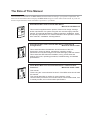
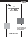
The Role of This Manual
Three manuals are available for the MPC series. Read the manual according to your specific requirements. The
below lists all the manuals that accompany the MPC series and gives a brief outline of the manual. If you do not
have the required manual, contact Yamatake Corporation or your dealer.
123E
C P-UM-0
nual
User's Ma
WARNING
CAUTION
Panel Mount Mass Flow Controller MPC Series
Manual No.CP-UM-5317E
WARNING
CAUTION
This manual is supplied with the product. Personnel in charge of design
and/or manufacture of a system using this unit must thoroughly read this
manual. This manual describes the safety precautions, installation, wiring
and primary specifications. For further information about operation, refer to
other manuals, "Installation & Configurations".
Panel Mount Mass Flow Controller MPC Series "Installation &
Configurations"
Manual No.CP-SP-1153E
This manual describes the hardware and all functions of this unit.
Personnel in charge of design, manufacture, operation, and/or
maintenance of a system using this unit must thoroughly read this manual.
This manual also describes the installation, wiring, all functions and
settings of this unit, operating procedures, troubleshooting, and detailed
specifications.
Panel Mount Mass Flow Controller MPC Series "Communication
Functions"
Manual No.CP-SP-1154E
This manual.
Those using the "communication functions" of the MPC series should read
this manual.
This manual describes an outline of communications, wiring,
communication procedures, a list of MPC series communication data, how
to remedy trouble, and communication specifications.
iii
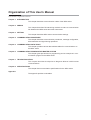
Organization of This User's Manual
This manual is organized as follows:
Chapter 1. INTRODUCTION
This chapter describes communication outline of the MPC series.
Chapter 2. WIRING
This chapter describes RS-485 wiring methods to make a communication
link between the MPC series and other instruments.
Chapter 3. SETTING
This chapter describes MPC series communication settings.
Chapter 4. COMMUNICATION PROCEDURE
This chapter describes communication procedures, message configuration,
data read/write and signal timing operations.
Chapter 5. COMMUNICATION DATA TABLE
This chapter provides various data address tables for communications on
the MPC series.
Chapter 6. COMMUNICATION PROGRAM FOR MASTER STATION
This chapter gives precautions for programming and an example of a communication program for the MPC series.
Chapter 7. TROUBLESHOOTING
This chapter describes checkpoints to diagnose failures in MPC series
communications.
Chapter 8. SPECIFICATIONS
This chapter lists communication specifications for the MPC series.
Appendix
The appendix provides code tables.
iv
Contents
SAFETY PRECAUTIONS
The Role of This Manual
Organization of This User's Manual
Conventions Used in This Manual
Chapter 1.
INTRODUCTION
Chapter 2.
WIRING
Chapter 3.
SETTING
■ Setting method • • • • • • • • • • • • • • • • • • • • • • • • • • • • • • • • • • • • • • • • • • • • • • • • • • • • • • • • • 3-1
■ Setting items of communication • • • • • • • • • • • • • • • • • • • • • • • • • • • • • • • • • • • • • • • 3-1
Chapter 4.
COMMUNICATION PROCEDURE
4-1 Outline of Communication Procedure and Messages • • • • • • • • • • • • • • • • • • • • • • 4-1
■ Communication procedure • • • • • • • • • • • • • • • • • • • • • • • • • • • • • • • • • • • • • • • • • • • • • 4-1
■ Message configuration • • • • • • • • • • • • • • • • • • • • • • • • • • • • • • • • • • • • • • • • • • • • • • • • • 4-1
■ Examples • • • • • • • • • • • • • • • • • • • • • • • • • • • • • • • • • • • • • • • • • • • • • • • • • • • • • • • • • • • • • • 4-2
■ Data address concept • • • • • • • • • • • • • • • • • • • • • • • • • • • • • • • • • • • • • • • • • • • • • • • • • • 4-2
4-2 Data Link Layer • • • • • • • • • • • • • • • • • • • • • • • • • • • • • • • • • • • • • • • • • • • • • • • • • • • • • • • • • • • • 4-3
■ Description• • • • • • • • • • • • • • • • • • • • • • • • • • • • • • • • • • • • • • • • • • • • • • • • • • • • • • • • • • • • • 4-3
4-3 Application Layer • • • • • • • • • • • • • • • • • • • • • • • • • • • • • • • • • • • • • • • • • • • • • • • • • • • • • • • • • • 4-6
■ Outline • • • • • • • • • • • • • • • • • • • • • • • • • • • • • • • • • • • • • • • • • • • • • • • • • • • • • • • • • • • • • • • • • 4-6
4-4 Data Read • • • • • • • • • • • • • • • • • • • • • • • • • • • • • • • • • • • • • • • • • • • • • • • • • • • • • • • • • • • • • • • • • • 4-7
■ Description of read instruction• • • • • • • • • • • • • • • • • • • • • • • • • • • • • • • • • • • • • • • • • 4-7
■ Read response • • • • • • • • • • • • • • • • • • • • • • • • • • • • • • • • • • • • • • • • • • • • • • • • • • • • • • • • • 4-8
■ Decimal numeric expression (numeric data) • • • • • • • • • • • • • • • • • • • • • • • • • • • 4-9
4-5 Data Write • • • • • • • • • • • • • • • • • • • • • • • • • • • • • • • • • • • • • • • • • • • • • • • • • • • • • • • • • • • • • • • • 4-10
■ Description of write instruction • • • • • • • • • • • • • • • • • • • • • • • • • • • • • • • • • • • • • • • 4-10
■ Write response • • • • • • • • • • • • • • • • • • • • • • • • • • • • • • • • • • • • • • • • • • • • • • • • • • • • • • • 4-11
4-6 Termination Code Table • • • • • • • • • • • • • • • • • • • • • • • • • • • • • • • • • • • • • • • • • • • • • • • • • • 4-12
■ Normal and warning termination • • • • • • • • • • • • • • • • • • • • • • • • • • • • • • • • • • • • • • 4-12
■ Error termination • • • • • • • • • • • • • • • • • • • • • • • • • • • • • • • • • • • • • • • • • • • • • • • • • • • • • 4-12
4-7 Timing Specifications • • • • • • • • • • • • • • • • • • • • • • • • • • • • • • • • • • • • • • • • • • • • • • • • • • • • 4-13
■ Timing specifications for instruction and response messages • • • • • • • 4-13
■ RS-485 driver control timing specifications• • • • • • • • • • • • • • • • • • • • • • • • • • • 4-13
■ Other precautions • • • • • • • • • • • • • • • • • • • • • • • • • • • • • • • • • • • • • • • • • • • • • • • • • • • • 4-14
v
Chapter 5.
COMMUNICATION DATA TABLE
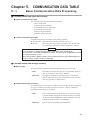
5-1 Basic Communication Data Processing • • • • • • • • • • • • • • • • • • • • • • • • • • • • • • • • • • • 5-1
■ Communication data types and formats • • • • • • • • • • • • • • • • • • • • • • • • • • • • • • • 5-1
■ Communication data storage memory • • • • • • • • • • • • • • • • • • • • • • • • • • • • • • • • • 5-1
■ Data address • • • • • • • • • • • • • • • • • • • • • • • • • • • • • • • • • • • • • • • • • • • • • • • • • • • • • • • • • • • 5-2
■ Number of data read / write • • • • • • • • • • • • • • • • • • • • • • • • • • • • • • • • • • • • • • • • • • • • 5-2
■ Data unit and decimal point position • • • • • • • • • • • • • • • • • • • • • • • • • • • • • • • • • • • 5-2
5-2 Communication Data Table • • • • • • • • • • • • • • • • • • • • • • • • • • • • • • • • • • • • • • • • • • • • • • • • 5-3
■ Device related data• • • • • • • • • • • • • • • • • • • • • • • • • • • • • • • • • • • • • • • • • • • • • • • • • • • • • 5-3
■ Operating status related data • • • • • • • • • • • • • • • • • • • • • • • • • • • • • • • • • • • • • • • • • • 5-4
■ Instantaneous flow related data • • • • • • • • • • • • • • • • • • • • • • • • • • • • • • • • • • • • • • • • 5-5
■ Integrated flow related data • • • • • • • • • • • • • • • • • • • • • • • • • • • • • • • • • • • • • • • • • • • • 5-5
■ Function setup related data • • • • • • • • • • • • • • • • • • • • • • • • • • • • • • • • • • • • • • • • • • • • 5-6
■ Parameter setup related data • • • • • • • • • • • • • • • • • • • • • • • • • • • • • • • • • • • • • • • • • • 5-9
Chapter 6.
COMMUNICATION PROGRAM FOR MASTER STATION
6-1 Precautions for Programming • • • • • • • • • • • • • • • • • • • • • • • • • • • • • • • • • • • • • • • • • • • • • 6-1
6-2 Example of Communication Program • • • • • • • • • • • • • • • • • • • • • • • • • • • • • • • • • • • • • • 6-2
■ Prior to running the sample program • • • • • • • • • • • • • • • • • • • • • • • • • • • • • • • • • • 6-2
■ Running the sample program • • • • • • • • • • • • • • • • • • • • • • • • • • • • • • • • • • • • • • • • • • 6-2
■ Data read/write sample program • • • • • • • • • • • • • • • • • • • • • • • • • • • • • • • • • • • • • • • 6-3
Chapter 7.
TROUBLESHOOTING
■ Check items in case communication is disabled • • • • • • • • • • • • • • • • • • • • • • • 7-1
Chapter 8.
SPECIFICATIONS
■ RS-485 specifications • • • • • • • • • • • • • • • • • • • • • • • • • • • • • • • • • • • • • • • • • • • • • • • • • • 8-1
APPENDIX
■ Code table• • • • • • • • • • • • • • • • • • • • • • • • • • • • • • • • • • • • • • • • • • • • • • • • • • • • • Appendix-1
■ Connection with CMC10L • • • • • • • • • • • • • • • • • • • • • • • • • • • • • • • • • • • • • Appendix-2
vi
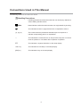
Conventions Used in This Manual
The following conventions are used in this manual:
Handling Precautions
: Handling precautions indicate items that the user should pay attention to
when handling the MPC series.
Note
: Notes indicate useful information that the user might benefit by knowing.
: This indicates the item or page that the user is requested to refer to.
(1), (2), (3)
: The numbers with the parenthesis indicate steps in a sequence or
indicate corresponding parts in an explanation.
>>
: This indicates the contents shown on the personal computer or unit as a
result of operation or unit status after completion of operation.
0FF
: This indicates 7-segment indication on the setup display.
"OK" lamp
: This indicates an LED lamp on the setup display.
[ENT] key
: This indicates a key on the setup display.
vii
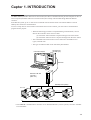
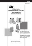
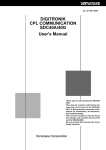
Capter 1. INTRODUCTION
The MPC series (hereafter referred to as slave station) are able to communicate with personal computer or PLC as
a host computer (hereafter referred to as master station) about setup value and data throgh RS-232C/RS-485
converter.
In the RS-485 system, up to 31 units can be connected with one master station. The station address is used to
identify slave station for communication.
To write a setup value or read a monitor from master station to slave station, you must write a communication
program for this purpose.
• When the following procedure is completed during communication, various
data for the controller can be read or written:
(1) The master station transmits a request message to the slave station.
(2) The master station receives a response message from the slave station.
• The commands from master station to slave station are classified into two
types; read and write.
• The type of read/write data can be selected by data address.
RS-232C port
(D-SUB 9 pin)
Personal Computer
RS-232C
DC IN
SD
PWR/RD
RS-232C
RS-232C / RS-485
converter *
(CMC 10L)
11
12
RS-485
13
14
15
RS-485(3-wire system)
This unit
Max. 31 units
* The CMC10L communication controller is an RS-232C/RS-485 (3-wires system) converter available
from Yamatake.
1-1
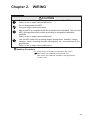
Chapter 2.
WIRING
CAUTION
Be sure to turn off the power supply when you connect the MPC.
Failure to do so might cause malfunction.
Do not disassemble the MPC.
Doing so might cause malfunction.
Wire the MPC in compliance with the predetermined standards. Also wire the
MPC with specified power cables according to recognized installation
methods.
Failure to do so might cause malfunction.
Use the MPC within the operating ranges (temperature, humidity, voltage,
vibration, shock, mounting direction, atmosphere, etc.) recommended in the
specifiations.
Failure to do so might cause malfunction.
Handling Precautions
• For wiring except for RS-485 communication line, refer to
MPC series User's Manual CP-UM-5317E and
MPC series User's Manual "Installation & Configurations"
CP-SP-1153E.
2-1
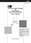
Chapter 2. WIRING
An example of connection methods is shown below.
MPC series
(Slave station)
Terminating
resistor
7
8
9
7
8
9
DA
DB
SG
DA
DB
SG
Shield
FG
Master station
DA
DB
SG
FG
Shield
FG
MPC series
(Slave station)
7
Terminating
resistor
8
9
DA
DB
SG
Handling Precautions
• Connect terminating resistors of 150Ω±5%, 1/2W or more to the both
ends of the communication path.
• Ground the shield to the FG at one end of the shiled.
Make sure that the shield is not grounded at both ends of the shield.
• On 3-wire system, Yamatake’s CMC10L001A000 controller can be
used as a converter of the master station.
• Be sure to connect SG terminals each other.
Failure to do so might cause unstable communications.
2-2
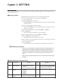
Capter 3. SETTING
Before starting communication, set the communication condition and station address of the slave station to meet
that of the master station.
■ Setting method
Operate the following procedure to set the communication functions:
(1) Put the integrated display mode by pressing the [DISP] key.
>>The "L" lamp lights.
(2) Keep pressing the [<] key for about 3s.
>> The 0.rMG displays on the upper display and the mode transit the parameter settings mode.
(3) Keep pressing the [<] key for about 3s again.
>> The item No.C-0 1 appears on the upper display and the mode transit the
function setting mode.
] key or [
] key.
<
<
(4) Select a target setting item by pressing either [
(5) Press the [ENT] key.
>> The current setting value blinks on the lower display.
] key.
<
] key or [
<
(6) Select a target setting by pressing either [
(7) Press the [ENT] key at the target setting.
>> The setting value stores in memory and renews.
(8) When wanting to set another setting items, return to (4) operation, and wanting
no more, go to (9) operation.
(9) Press the [DISP] key
>> The mode returns to the normal display of instantaneous PV indication.
Handling Precautions
• If any key is not pressed for 1min after the function settings mode, the
mode returns to the normal display of instantaneous PV indication.
• When pressing the [DISP] key without pressing the [ENT] key after (6)
operation, the setting is not renewed but remained as the previous
value.
• When setting a station address zero, the communication function does
not work.
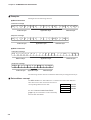
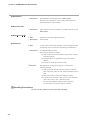
■ Setting items of communication
Display
Description
Contents
Initial
Remarks
value
C-30
Station address
0: Communications function
disabled
1 to 127: Communications address
0
C-3 1
Transmisson speed
selection
0:
1:
2:
3:
4:
1
C-32
Communications
condition
0: 8 bits data, even parity, 1 stop bit
1: 8 bits data, no parity, 2 stop bits
38400bps
19200bps
9600bps
4800bps
2400bps
The communications function does
not work at 0. Set a different address among the slave stations.
0
3-1
Capter 4. COMMUNICATION PROCEDURE
4-1
Outline of Communication Procedure and Messages
This chapter describes the outline of communication procedure and the concept behind message configuration.
■ Communication procedure
The following is a simple breakdown of the communication procedure:
(1) The master station transmits an instruction message to a slave station to specify
a station for communication.
(2) The slave station processes the instruction message, and executes read and
write operations.
(3) The slave station transmits a response message according to the contents of
processing.
(4) The master station receives the response message and executes processing.
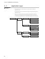
■ Message configuration
A message consists of two layers as shown below. Both the instruction message
from a master station and the response message from a slave station take this form.
●
Data link layer
• This layer contains the basic information required for communication.
• It also contains message destination and check information.
●
Application layer
• This layer is where data read and write operations are executed.
• The content of this layer varies according to the purpose of the operation.
The figure below shows the individual layers.
Application layer
A total of 31 units
Data link layer
Instruction message from master station
Response message from slave station
Master station
Slave stations
Application layer
Data link layer
The driver of the data link layer knows:
¥ Destination (station address)
¥ Load check sheet (checksum)
The load (data) of the application layer
changes every time according to the
purpose of the operation.
4-1
Chapter 4. COMMUNICATION PROCEDURE
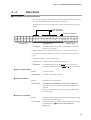
■ Examples
Messages have the following structure:
● Read instruction
Instruction message
STX
0
1
0
0
X
R
S
,
Data link layer
1
0
0
1
W
,
2
ETX
Application layer
9
A
CR
LF
Data link layer
Response message
STX
0
1
0
0
X
0
0
Data link layer
,
0
,
4
2
ETX
9
4
CR
LF
Data link layer
Application layer
● Write instruction
Instruction message
STX
0
1
0
0
X
W
S
,
Data link layer
1
0
0
1
W
,
Application layer
5
8
ETX
5
A
CR
LF
Data link layer
Response message
STX
0
1
0
Data link layer
0
X
0
0
ETX
Application layer
8
2
CR
LF
Data link layer
The following sections describe in detail the data link layer and application layer:
■ Data address concept
The MPC series uses "data addresses" to read and write data. Data addresses
allow data to be written and read to and from a
corresponding address for the data.
Data A
1001W
See 5-2 "Communication Data Table"
(page 5-3) for information on the relationship
between data and address.
4-2
Data B
Data C
:
1002W
1003W
:
Chapter 4. COMMUNICATION PROCEDURE
4-2
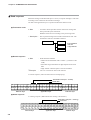
Data Link Layer
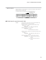
■ Description
• The data link layer contains eight types of basic message transmission
information.
• The instruction message and response message have the same structure in the
data link layer.
ETX
Checksum
STX
Station address
Subaddress
Device ID code
CR
LF
02H 30H 41H 30H 30H 58H 52H 53H 2CH 31H 30H 30H 31H 57H 2CH 32H 03H 38H 41H 0DH 0AH
STX
0
A
0
0
X
R
S
Data link layer
,
1
0
0
1
W
,
2
ETX
Application layer
8
A
CR
LF
Data link layer
The following describes each function of the data link layer:
● STX (Start of TeXt)
✦ Role
: Indicates the beginning of a message.
✧ Description • Fixed at 02H.
• When the instrument receives an STX, it is identified as the
first character of a new instruction message regardless of
location with a message.
● Station address
✦ Role
: Specifies the destination station, and allows communication
with the specified station.
✧ Description • If "0" is set as the station address, the communication function
is disabled. So, to enable communication be sure to set an
address value of "1" or more.
• Two hexadecimal characters. For details, see the example.
❐ Example
: When the station address of the destination is "10":
(1) 10 (decimal) = 0AH (hexadecimal)
(2) Converting into character codes:
0 = 30H, A = 41H
(3) "0A" (30H, 41H) is used as the station address.
Note
See Chapter 3 "SETTING" for information on station address settings.
Handling Precautions
• Note that the function of the station address differs entirely from that
of the data address of the application layer.
4-3
Chapter 4. COMMUNICATION PROCEDURE
● Subaddress
✧ Description : The subaddress is meaningless on the MPC series.
Be sure to set a subaddress of "00" (30H, 30H) that has the
same format as the station address.
● Device ID code
✧ Description : Only character codes "X" (58H) or "x" (78H) can be set on the
MPC series.
● ETX (End of TeXt)
✦ Role
: Indicates the end of the application layer.
✧ Description : Fixed at 03H.
● Checksum
✦ Role
: A value to be used to check whether or not a message has been
corrupted by an error (such as noise) during communication.
✧ Description • Two hexadecimal characters.
• This function operates as follows:
(1) Add one byte each to the character codes of the message
from STX to ETX.
(2) Calculate the two's complement of the result of this
addition.
(3) Convert the result into character codes.
❐ Example
: The instruction message on the page 4-3 is used in the
following example:
(1) Add one byte each to the character codes from STX to
ETX. The lower-order one byte of the calculation result is
76H.
(2) The result of two's complement addition is 8AH.
(3) Converted into character codes and use as the checksum
value. The result is "8A", (38H) and (41H).
See the station address example (on the page 4-3)
for information on character code conversion.
Handling Precautions
• Do not omit the checksum in the instruction message .
4-4
Chapter 4. COMMUNICATION PROCEDURE
● CR and LF (Carriage Return / Line Feed)
✦ Role
: Indicates the end of a message.
✧ Description • "CR" is (0DH), and "LF" is (0AH).
• Be sure to use CR and LF in pair.
Handling Precautions
●
If any of the following errors occur in the data link layer, the MPC series
does not respond:
• The communication conditions for both stations do not match
(different transmission speeds or the occurrence of a parity error).
• STX, ETX, CR and LF are not placed at the right positions.
• The device ID code is neither "X" nor "x".
• The station address, subaddress or checksum is not two character
codes.
• The calculation of the checksum does not agree with that of the
message.
• Non-specified characters are included in the message.
• The destination station address differs from the station address for
the receiving station.
• The station address set to "00".
●
The contents of the data link layer of the response message are same as
the instruction message except for the checksum function.
●
Use capital letters "A" to "F" in the hexadecimal numerics for the station
address and checksum.
4-5
Chapter 4. COMMUNICATION PROCEDURE
4-3
Application Layer
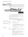
■ Outline
• The application layer contains instructions, data, number of data and
termination code.
• In the application layer, the instruction message and response message have a
different structure.
• There are two types of instruction messages: read instructions and write
instructions. Each of these instruction messages have their own responses.
• A termination code indicates how an instruction message has been processed.
Application layer
Instruction
message
Read instruction
Command (RS)
Start data address
Number of read data
Write instruction
Command (WS)
Start data address
Write data
Response
message
Read response
Termination code
Read data
Write response
4-6
Termination code
Chapter 4. COMMUNICATION PROCEDURE
4-4
Data Read
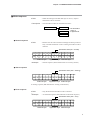
■ Description of read instruction
• This instruction permits the contents of continuous data addresses starting from
the specified start data address to be read in one message.
• The application layer of a read instruction consists of the following three types
of data:
Read command
Start data address
Number of read data
02H 30H 31H 30H 30H 58H 52H 53H 2CH 31H 30H 30H 31H 57H 2CH 32H 03H 39H 41H 0DH 0AH
STX
0
1
0
0
X
R
S
Data link layer
,
1
0
0
1
W
,
2
Application layer
❐ Example
ETX
9
A
CR
LF
Data link layer
: The above example shows that two-data items are read from
1001W as one message.
• Individual data items are delimited by a comma "," (character code 2CH).
• An capital letter code is used for each numeric or character in the application
layer.
• A decimal number is used for each numeric.
• Additional "0"s or spaces cannot be added to each data item.
❐ Example
: The underlined portion of "RS,01001W,2" is not allowed.
The underlined portions of "RS, 1001W,02" are not allowed.
● Read command (RS)
✦ Role
: A read command
✧ Description : Two "RS" (52H, 53H) characters
● Start data address
✦ Role
: Specifies the start data address.
✧ Description • See Chapter 5 "COMMUNICATION DATA TABLE" for
information on the relationship between data addresses and
read data.
• Be sure to append the numeric representing the data address
with "W" (57H).
● Number of read data
✦ Role
: Specifies how many data items are read continuously, starting
with the specified data address.
✧ Description : There is a limit for the number of data to read in one message.
For details refer to ■ Number of data read/write
(page 5-2).
4-7
Chapter 4. COMMUNICATION PROCEDURE
■ Read response
When the message in the data link layer is correct, a response message is sent back
according to the contents of the instruction message.
All data in the application layer is expressed in decimal character code.
● Termination code
✦ Role
: A numeric which specifies how the instruction message has
been processed by the instrument.
Different values are set according to the processing result.
✧ Description : The response message must include a termination code. The
termination codes are classified as follows:
Termination code
Normal
*The termination
code is a
2-digit decimal.
Alarm
Error
● Normal response
✦ Role
: Sends back the read data.
• Data items are delimited with a comma "," (character code
2CH).
• Each data range and number of digits depend on the read
data.
• Digit without a decimal point is used for read data.
❐ Example
: "20.0" is converted to "200" when entered.
A normal response. (when two data items are read properly.)
Termination code (00 = normal)
Read data
02H 30H 31H 30H 30H 58H 30H 30H 2CH 31H 32H 33H 2CH 38H 37H 30H 03H 46H 35H 0DH 0AH
STX
0
1
0
0
X
0
0
,
1
Data link layer
2
3
,
8
7
0
ETX
Application layer
F
5
CR
LF
Data link layer
● Alarm response
A warning response. (❈❈ indicates the warning code numeric.)
Termination code (❈❈ = warning)
Read data
02H 30H 31H 30H 30H 58H ❈H ❈H 2CH 30H 2CH 38H 37H 30H 03H ??H ??H 0DH 0AH
STX
0
1
0
0
Data link layer
4-8
X
❈
❈
,
0
,
8
Application layer
7
0
ETX
?
?
CR LF
Data link layer
Chapter 4. COMMUNICATION PROCEDURE
● Error response
Indicates that there is an abnormality in an instruction message, which contains no
data and cannot be normally read.
A warning response. (❈❈ indicates the warning code numeric.)
Termination code
(❈❈ = error)
02H 30H 31H 30H 30H 58H ❈H ❈H 03H ??H ??H 0DH 0AH
STX
0
1
0
Data link layer
0
X
❈
❈
ETX ??
Application layer
??
CR
LF
Data link layer
■ Decimal numeric expression (numeric data)
✦ Role
: All the numeric, read count, write value and read data in the
data address follow the rules given below.
(1)When a numeric is negative, prefix the numeric with a
minus sign "-" (2DH).
❐ Example: "-123" (2DH, 31H, 32H, 33H)
(2)When a numeric is "0", use one "0".
❐ Example: "0" (30H)
"00" (30H, 30H) is not allowed.
(3)When a numeric is positive, never prefix the numeric with a
plus sign "+".
❐ Example: "+123" (2BH, 31H, 32H, 33H) is not
allowed.
(4)Never add additional "0"s or spaces before a numeric.
❐ Example: "0123" (30H, 31H, 32H, 33H) is not
allowed.
" 123" (20H, 31H, 32H, 33H) is not
allowed.
4-9
Chapter 4. COMMUNICATION PROCEDURE
4-5
Data Write
■ Description of write instruction
• This instruction permits the contents of continuous data addresses starting with
the specified start data address to be simultaneously written in one message.
• The application layer of a write instruction consists of the following three types
of data:
Write command
Write data (1st data item)
Write data (2nd data item)
Start data address
02H 30H 31H 30H 30H 58H 57H 53H 2CH 31H 30H 30H 31H 57H 2CH 32H 2CH 36H 35H
STX
0
1
0
0
X
W
S
,
1
0
0
1
W
,
2
,
6
5
Application layer
Data link layer
03H 46H 45H 0DH 0AH
ETX
F
E
CR
LF
Data link layer
•
•
•
•
•
❐ Example : The above example shows that "2" and "65" are written at
address 1001W and 1002W in one message.
Individual data items are delimited with a comma "," (character code 2CH).
The number of write data does not need to specify.
A capital letter code is used for each numeric or character in the application
layer.
A decimal number is used for each numeric.
Additional "0"s (30H) or spaces cannot be added to each data item.
❐ Example : The underlined portion of "WS,01001W,1" is not allowed.
The underlined portions of "WS, 1001W,01" are not allowed.
● Write command (WS)
✦ Role
: A write command
✧ Description : Two "WS" (57H, 53H) characters
● Start data address
✦ Role
: Specifies the start data address.
• See 5-2 "Communication Data Table" (page 5-3) for
information on the relationship between data addresses and
write data.
• Be sure to append the numeric representing the data
address with "W" (57H).
✦ Role
: Data to be written to continuous addresses starting with the
specified data address.
● Write data
✧ Description • The range of a numeric to be written differs according to each
data address.
• Individual data are delimited by a comma "," (2CH).
• The data address at which the corresponding data is written, is
incremented by 1 sequentially, starting with the start data
address (see the example above).
• The number of data item which can be written in one message
is limited. See ■ Number of data read / write (page 5-2)
for details.
4-10
Chapter 4. COMMUNICATION PROCEDURE
■ Write response
✦ Role
: When the message in the data link layer is correct, only the
termination code is sent back.
✧ Description : The termination codes are classified as follows:
Termination code
Normal
*The termination
code is a
2-digit decimal.
Alarm
Error
● Normal response
✦ Role
: Returns how the write instruction message has been processed.
Only a normal termination code or warning termination code is
returned.
Termination code (00 = normal)
02H 30H 31H 30H 30H 58H 30H 30H 03H 38H 32H 0DH 0AH
STX
0
1
0
0
Data link layer
❐ Example
X
0
0
ETX
Application layer
8
2
CR
LF
Data link layer
: Normal response (when all data items are correctly written)
● Alarm response
Termination code (❈❈ = warning)
02H 30H 31H 30H 30H 58H ??H ??H 03H ??H ??H 0DH 0AH
STX
0
1
0
0
Data link layer
X
❈
❈
ETX
Application layer
?
?
CR
LF
Data link layer
A warning response (❈❈ indicates the warning code numeric.)
● Error response
✦ Role
: Only the abnormal termination code is returned.
❐ Example
: An abnormal response (❈❈ indicates an abnormal response.)
Termination code (❈❈ = error)
02H 30H 31H 30H 30H 58H ❈H ❈H 03H ??H ??H 0DH 0AH
STX
0
1
0
0
Data link layer
X
❈
❈
ETX
?
?
CR
LF
Application layer Data link layer
4-11
Chapter 4. COMMUNICATION PROCEDURE
4-6
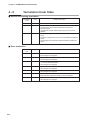
Termination Code Table
■ Normal and warning termination
Termination
code
Type
Contents and action
00
Normal
21
Alarm
Wrote data in the address that could not be set in the
communication due to the setup allotment by external
switching inputs.
Continue the process without writing any in the concerned
address.
23
Alarm
The Read is stopped due to access to the address outside the
scope.
The Write is stopped due to access to the address outside the
scope.
All messages are processed except the address outside the
scope.
Termination
code
Type
Contents and action
40
Error
"W" has not been set at the address.
All messages are scrapped.
41
Error
"WS", or "RS" has not been set.
All messages are scrapped.
43
Error
ETX(03H) is not set in the correct position.
"," is not set after the address.
All messages are scrapped.
46
Error
The address is erroneous.
All messages are scrapped.
47
Error
There is an error in the written numeric.
All messages are scrapped.
48
Error
There is an error in the written numeric.
Write has been executed, except for the error address.
99
Error
An undefined command or other message error.
All messages are scrapped.
Normal end
■ Error termination
4-12
Chapter 4. COMMUNICATION PROCEDURE
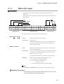
4-7
Timing Specifications
■ Timing specifications for instruction and response messages
The following precautions regarding the transmission timing of instruction
messages from the master station and response messages from the slave station
should be observed:
● Response time-out
The maximum response time from the end of the instruction message transmission
by the master station until when the master station receives a response message
from the slave station is 2 seconds ((1) in figure). So, the response time-out should
be set to 2 seconds.
Generally, when a response time-out occurs, the instruction message is resent.
For details, see Chapter 6 "COMMUNICATION PROGRAM FOR MASTER
STATION."
● Transmission start time
(1)
Transmission
line
(2)
Instruction
message
Response
message
Instruction
message
Response
message
(1) End of master station transmission - Transmission start time of slave station = 2s max.
(For the master station, the response time-out after the end of instruction message transmission
should e set to 2s.)
(2) End of slave station transmission - Transmission start time of master station = 10ms min.
(For the master station, stand by for 10ms or more from the end of response message receipt to
the start time of next transmission.)
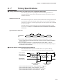
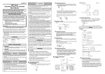
■ RS-485 driver control timing specifications
When the transmission/reception on the RS-485 3-wire system is directly
controlled by the master station, care should be paid to the following timing:
(1)
Master station
Driver control
Transmission line
Slave station
Driver control
(4)
(enable)
(disable)
Effective
data
(instruction message)
(disable)
Effective
data
(response message)
(enable)
(2)
End of master station
transmission
(3)
End of slave station
transmission
(1) End of master station transmission - Driver disable time = 500 s max.
(2) End of slave station reception - Driver enable time = 15ms min.
(3) End of slave station transmission - Driver disable time = 10ms max.
(4) End of master station reception - Driver enable time = 10ms min.
4-13
Chapter 4. COMMUNICATION PROCEDURE
■ Other precautions
• The time required for the master station to finish the transmittal of instruction
message and for the slave station to start the transmittal of response message
becomes longer if the number of data to write and read increases.
When the faster response time is required by the slave station, make sure to
keep the number of data to read / write at the minimum in one message.
• When the number of data is one data to read / write in one message, the time
required for the master station to finish the instruction message and for the
slave station to transmit the response message is about 30ms.
4-14
Chapter 5.
5-1
COMMUNICATION DATA TABLE
Basic Communication Data Processing
■ Communication data types and formats
● Types of communication data
The communications data are categorized as follow:
• Device related data
• Operating status related data
• Instantaneous flowrate related data
• Integrated flow related data
• Function setup related data
• Parameter setup related data
● Format of communication data
Communication data is classified into the following formats:
● Numeric data: Data indicating a numeric value (PV, SP, etc.).
● Bit data:
Data where each bit is significant (alarms, etc.). Bit data must
be composed by transmission and decomposed by reception.
IMPORTANT
If it is necessary to change the parameters of the MPC series frequently by
communication, write data at addresses of RAM. The endurance of EEPROM is limited
to 10,000 erase/write cycles.
Note, that the data in RAM is cleared, and is replaced with the data in EEPROM if the
power supply to the MPC series is interrupted.
■ Communication data storage memory
● Memory type
The communication data are stored in the following two types of memory:
• RAM:
Stored data is cleared when the power is turned OFF. However
data can be written to this memory infinitely.
• EEPROM:
Stored data is retained even when the power is turned OFF,
whereas data erase/write cycles are limited to a total of 10,000
times owing to device characteristics.
● Communication object memory
In communication, it is necessary to read/write data from/into the abovementioned
two types of memory according to the purpose and use. There is a difference
between the object memories as follows:
• RAM:
Data is read/written from/into RAM only. If the power supply
is turned off after writing data into RAM, and then it is turned
on again, the data in EEPROM is copied on RAM, so the data
in RAM becomes the same as in EEPROM.
• EEPROM:
Data are written in both RAM and EEPROM.
5-1
Chapter 5. COMMUNICATION DATA TABLE
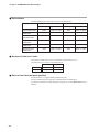
■ Data address
The data addresses are allocated as shown in the table below.
Communication data
RAM
EEPROM
Offset value
Address
Offset value
Address
Device related data
1000
1001 to 1199
4000
4001 to 4199
Operating status
related data
1200
1201 to 1399
4200
4201 to 4399
Instantaneous flowrate related data
1400
1401 to 1599
4400
4401 to 4599
Integrated flowrate
related data
1600
1601 to 1799
4600
4601 to 4799
Function setup
related data
2000
2001 to 2199
5000
5001 to 5199
Parameter setup
related data
2200
2201 to 2399
5200
5201 to 5399
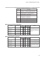
■ Number of data read / write
The number of data which can be continuously read/written by once
communication is as shown in the tabble below.
RAM
EEPROM
Read
1 to 10 words
1 to 10 words
Write
1 to 10 words
1 to 10 words
■ Data unit and decimal point position
Read/write data is not appended with a decimal point.
The unit and decimal point position is determined for each data item.
For details on the data unit and decimal point position, see the MPC series User's
Manual.
5-2
Chapter 5. COMMUNICATION DATA TABLE
5-2
Communication Data Table
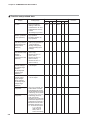
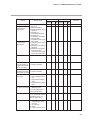
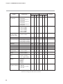
The enabling conditions for the address and R/W (Read/Write) of each data are specified in the following table:
The meaning of R/W column marks:
❍ Possible
✕ Impossible
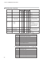
■ Device related data
Display
Data range
RAM
Address R
Gas type
Full- scale flow
0:
1:
3:
4:
User Setting
Nitrogen/Air
Argon
Carbon dioxide
Depended on each
flowrate range
EEPROM
W Address R
Remarks
W
1001
❍ ✕
4001
✕
✕ Change in gas type is possible
with the function setup
(Address 5018).
1002
❍ ✕
4002
✕
✕ The value with excluded
decimal point.
Decimal point
display position
of instantaneous
flowrate
0:
1:
2:
3:
4:
No decimal point
XXXX.
XXX.X
XX.XX
X.XXX
1003
❍ ✕
4003
✕
✕
Decimal point
display position
of integrated
flowrate
0:
1:
2:
3:
4:
No decimal point
XXXXXXXX.
XXXXXXX.X
XXXXXX.XX
XXXXX.XXX
1004
❍ ✕
4004
✕
✕
5-3
Chapter 5. COMMUNICATION DATA TABLE
■ Operating status related data
Display
Data range
RAM
Address R
EEPROM
W Address R
Remarks
W
Alarm status bit
Refer to *1
1201
❍ ✕
4201
✕
✕ Status is shown in decimal
numbers
Event status bit
Refer to *2
1202
❍ ✕
4202
✕
✕ Status is shown in decimal
numbers
Control status bit Refer to *3
1203
❍ ✕
4203
✕
✕ Status is shown in decimal
numbers
Operation mode
0: Valve full close
1: Valve control
2: Valve full open
1204
❍ ❍
4204
❍ ❍ Can not write when the valve
0:
1:
2:
3:
SP-0
SP-1
SP-2
SP-3
1205
Instantaneous
SP value in use
(0 to 100%FS)
L/min(standard)
1206
❍ ✕
4206
✕
Instantaneous
PV value
(0 to 100%FS)
L/min(standard)
1207
❍ ✕
4207
✕
Valve drive
current output
0.0 to 100.0%
1208
❍ ✕
4208
✕
Instantaneous SP
No. in use
is in full close or full open
resulted forcibly by external
inputs.
❍ ❍
4205
❍ ❍ Can not write when SP No.
switching is being selected by
external inputs.
The number larger than the
one being selected with SP
No.(Address 5004) of the
function setup can not be
written.
✕ The value with excluded
decimal point of flow (L/min
standard) multiplied by the
✕ percent in the full-scale flow
bracket.
✕ The value with excluded
decimal point.
*1 : Alarm status bit configuration (Address 1201)
Bit No.
Description
0
Flowrate deviation lower limit alarm
1
Flowrate deviation upper limit alarm
2
Undefined (normally 0)
3
Undefined (normally 0)
4
Sensor error
5
Input / output adjustment data error
6
Sensor calibration data error
7
User setup data error
8
Valve overheat prevention limit is operated
*2 : Event status bit configuration (Address 1202)
Bit No.
5-4
0: Nomal 1: Error
Description
0
Event output 1 status
1
Event output 2 status
2
Undefined (normally 0)
3
External switch input 1 status
4
External switch input 2 status
5
Undefined (normally 0)
6
Undefined (normally 0)
7
Undefined (normally 0)
0: OFF 1: ON
Chapter 5. COMMUNICATION DATA TABLE
*3 : Control status bit configuration (Address 1203)
Bit No.
0: OFF 1: ON
Description
0
OK lamp (Instantaneous PV control status)
0: Light-out 1: Lighting (Instantaneous PV OK)
1
Slow start operation
0: Normal operation 1: Slow start operation
2
Digital setting / Analog setting
0: Digital setting 1: Analog setting
3
Integrated count status
0: Integrated PV < Integrated SP
1: Integrated PV ≥ Integrated SP
4
Undefined (normally 0)
5
Undefined (normally 0)
6
Undefined (normally 0)
7
Undefined (normally 0)
■ Instantaneous flowrate related data
Display
Data range
RAM
Address R
EEPROM
W Address R
Remarks
W
Digital instantaneous
flowrate SP-0
(0 to 100%FS)
L/min(standard)
1401
❍ ❍
4401
❍ ❍ The value with excluded
Digital instantaneous
flowrate SP-1
(0 to 100%FS)
L/min(standard)
1402
❍ ❍
4402
❍ ❍ (standard)) multiplied by the
Digital instantaneous
flowrate SP-2
(0 to 100%FS)
L/min(standard)
1403
❍ ❍
4403
❍ ❍
Digital instantaneous
flowrate SP-3
(0 to 100%FS)
L/min(standard)
1404
❍ ❍
4404
❍ ❍
decimal point of flow (L/min
percent in the full-scale flow
bracket
■ Integrated flowrate related data
Display
Data range
RAM
Address R
Integrated SP setup
lower 4 digits
0 to 9999
Integrated SP setup
upper 4 digits
0 to 9999
Integrated PV setup
lower 4 digits
0 to 9999
Integrated PV setup
upper 4 digits
0 to 9999
1601
EEPROM
W Address R
❍ ❍
4601
Remarks
W
❍ ❍ Same as RAM address 2217
and 5217 in parameter set up
1602
❍ ❍
4602
❍ ❍ Same as RAM address 2218
and 5218 in parameter set up
1603
1604
❍ ❍
❍ ❍
4603
❍ ❍ When resetting the integrated
4604
value,make sure to write “0”
❍ ❍ for the both lower and upper
digits.
5-5
Chapter 5. COMMUNICATION DATA TABLE
■ Function setup related data
Display
EEPROM
Remarks
Address
R
W
Address
R
W
2001
❍
❍
5001
❍
❍
Operation mode
0: Disabled selection by
selection (selection
key operation
by key operation)
1: Enabled selection by
key operation
2002
❍
❍
5002
❍
❍
Instantaneous flow
-rate setup method
(instantaneous SP
setup method
selection)
2003
❍
×
5003
❍
×
Number of instanta- 0: Number of SPs = 1
neous flowrate setups
(SP-0 only)
selection
1: Number of SPs = 2
(number of
(SP-0, SP-1)
instantaneous SPs 2: Number of SPs = 3
selection)
(SP-0 to SP-2)
3: Number of SPs = 4
(SP-0 to SP-3)
2004
❍
❍
5004
❍
❍
Instantaneous
flowrate analog input voltage range
selection
(SP analog input
voltage range
selection)
0: 0 to 5V input
1: 1 to 5V input
2005
❍
×
5005
❍
×
*1
Instantaneous
flowrate analog
output voltage
range selection
(PV analog output
voltage range
selection)
0: 0 to 5V output
1: 1 to 5V output
2006
❍
×
5006
❍
×
*1
2007
❍
❍
5007
❍
❍
2008
❍
❍
5008
❍
❍
Key lock
0: Key lock disabled
1: Settings other than
instantaneous SP and
integrated SP are keylocked
2: All settings key-locked
0: Digital setup
(set by key operation or
communcations)
1: Analog setup (set by
external analog input
voltage)
Event 1 output type 0: Not used (normally OFF)
1: ON at alarm occurred
assignment
2: Integrated pulse output
3: ON at instantaneous PV OK
4: ON during control mode
Event 2 output type 5: ON during fully open mode
assignment
6: ON during control or
fully open mode
7: ON during fully closed mode
8: Instantaneous high limit event
9: Instantaneous low limit event 1
10:Instantaneous low limit event 2
11:Integrated flowrate event
-1 to -11:Reversed output
1 to 11 above.
(ON at normal
times, OFF at
event occurrence)
5-6
RAM
Setting range
*1
Chapter 5. COMMUNICATION DATA TABLE
Display
RAM
Setting range
EEPROM
Remarks
Address
R
W
Address
R
W
×
5009
×
❍
5010
❍
❍
Undefined
0
2009
External contact 1
input function
assignment
0: Not used
1: Reset integration
2: Stop integration count
operation
3: Switching of
instantaneous SP No.
4: Switching of
instantaneous flowrate
setup method
5: Operating mode forced
fully closed
6: Operating mode forced
fully open
7: Switching of slow start
operation
8: Switching of operation
mode (Control at
contact ON, forced fully
closed at contact OFF)
2010
❍
❍
2011
❍
❍
5011
❍
❍
External contact 2
input function
assignment
❍
Undefined
0
2012
❍
×
5012
❍
×
Automatic valve
shut-off function at
integrated flowrate
event occurrence
0: Function disabled
1: Function enabled
2013
❍
❍
5013
❍
❍
Switching of
0: Function disabled
integrated reset func- 1: Function enabled
tion at start of control
2014
❍
❍
5014
❍
❍
Flowrate alarm
setup type
2015
❍
❍
5015
❍
❍
Operation selection 0: Control continued
at alarm occurrence
(alarm ignored)
1: Forced fully closed
2: Forced fully open
2016
❍
❍
5016
❍
❍
Slow start setup
0: Slow start disabled
1 to 8: Slow start enabled
(equivalent to about 1 to 6
seconds settling time)
2017
❍
❍
5017
❍
❍
0: Conversion factor for
each gas type set by
the user
1: Air, nitrogen
3: Argon
4: Carbon dioxide (CO2)
2018
❍
❍
5018
❍
❍
Gas type selection
0: Function disabled
1: Only upper limit alarm
use
2: Only lower limit alarm
used
3: Upper/lower limit alarm
used
*1
*1
5-7
Chapter 5. COMMUNICATION DATA TABLE
Display
RAM
Setting range
EEPROM
Remarks
Address
R
W
Address
R
W
2019
❍
❍
5019
❍
❍
2020
❍
❍
5020
❍
❍
Instantaneous flow- 0: Function disabled
rate direct setting
1: Function enabled
functional change
2021
❍
❍
5021
❍
❍
Undefined
0
2022
×
5022
0:
1:
2:
3:
❍
5023
❍
❍
×
PV filter (Average)
❍
❍
Undefined
0
2024
×
5024
*1
0
2025
×
5025
×
*1
Undefined
0
2026
×
5026
×
*1
Undefined
0
2027
×
5027
×
*1
Analog optional
scaling function
0: Function disabled
1: Function enabled
2028
×
5028
❍
❍
❍
❍
❍
×
Undefined
❍
❍
❍
❍
❍
×
*1
PV forced zero
function
0: Function disabled
1: Function enabled
2029
❍
❍
5029
❍
❍
Station address
setting
0: Communication
functions disabled
1 to 127: Station address
2030
❍
✕
5030
❍
✕
*1
Transmission speed 0: 38400bps
selection
1: 19200bps
2: 9600bps
3: 4800bps
4: 2400bps
2031
❍
✕
5031
❍
✕
*1
Communication
0: 8 data bits, even parity,
conditions selection
1 stop bit
1: 8 data bits, no parity,
2 stop bits
2032
❍
✕
5032
❍
✕
*1
Flowrate display
unit selection
0: Referenced to 20˚C, 1
atmosphere
1: Referenced to 0˚C, 1
atmosphere
2: Referenced to 25˚C, 1
atmosphere
3: Referenced to 35˚C, 1
atmosphere
Inlet pressure setup 0:
1:
2:
3:
4:
5:
0 to 0.1MPa
0.05 to 0.15MPa
0.15 to 0.25MPa
0.25 to 0.35MPa
0.35 to 0.45MPa
0.45 to 0.5MPa
No filtering
Moving average of 2 samples
Moving average of 4 samples
Moving average of 8 samples
2023
*1
❍
*1: Though a normal termination code is returned after sending the write
instruction message, the data cannot be written.
5-8
Chapter 5. COMMUNICATION DATA TABLE
■ Parameter setup related data
Display
RAM
Setting range
EEPROM
Remarks
Address
R
W
Address
R
W
❍
❍
5201
❍
❍ The result
Instantaneous flowrate
O.K judgment range
(0.5 to 100%FS)
L/min(standard)
2201
Instantaneous flowrate
O.K judgment hysteresis
(0.5 to 100%FS)
L/min(standard)
2202
❍
❍
5202
❍
❍
Instantaneous flowrate
deviation high limit alarm
(0.5 to 100%FS)
L/min(standard)
2203
❍
❍
5203
❍
❍
Instantaneous flowrate
deviation high limit alarm
hysteresis
(0.5 to 100%FS)
L/min(standard)
2204
❍
❍
5204
❍
❍
Instantaneous flowrate
deviation lower limit alarm
(0.5 to 100%FS)
L/min(standard)
2205
❍
❍
5205
❍
❍
Instantaneous flowrate
deviation lower limit alarm
hysteresis
(0.5 to 100%FS)
L/min(standard)
2206
❍
❍
5206
❍
❍
Instantaneous flowrate
deviation alarm judgment
delay time
1.0 to 999.9s
2207
❍
❍
5207
❍
❍
Event 1 output delay time
0.0 to 999.9s
2208
❍
❍
5208
❍
❍ Even if the delay
Event 2 output delay time
User setup conversion
factor(C.F.)
becomes the
flowrate
(L/min(standard))
obtained by
multiplying the
full-scale flowrate
by the
percentage in
parentheses.
(The setting
range vary
according to the
model.)
0.0 to 999.9s
2209
❍
❍
5209
❍
time is set, it is
disabled during
❍ selection of
integration pulse
output.
0.100 to 9.999
2210
❍
❍
5210
❍
❍ Under the gas
type selection
(Address 5018) of
the function setup,
the setup value is
only effective
when the” User
setup” is selected.
2213
❍
❍
❍
5213
❍
❍
❍
❍
(0 to 100%FS)
L/min(standard)
2214
❍
5214
❍
❍
Undefined
0
2215
Undefined
0
2216
*1
5215
*1
5216
2217
❍
❍
❍
*1
5217
❍
❍
❍
(10 to 100%FS)
L/min(standard)
Integrated SP setup
lower 4 digits
0 to 9999
2218
❍
❍
5218
❍
Integrated SP setup
upper 4 digits
0 to 9999
Undefined
0
2211
Undefined
0
2212
Event 1 output
high-low limit flowrate setup
(0 to 100%FS)
L/min(standard)
Event 2 output
high-low limit flowrate setup
Analog option scaling
function
✕
5211
✕
5212
❍
❍
✕
*1
✕
*1
*1
*1
*1
❍ Same as address
1601 and 4601.
2219
❍
❍
5219
❍
❍ Same as address
1602 and 4602.
PV forced zero function
delay time
0.0 to 999.9s
2220
❍
❍
5220
❍
❍
*1: Though a normal termination code is returned after sending the write
instruction message, the data cannot be written.
5-9
Chapter 6. COMMUNICATION PROGRAM FOR MASTER STATION
6-1
Precautions for Programming
Pay attention to the following points when making communications programs:
• The longest response time on the device is 2s. For this reason, set the response monitor time to 2s.
• Resend the same message if there is no response within 2s. Set a communications error to occur if there is no
response even after 2 retries.
• Be sure to make the above resends to guard against the case when the message cannot be send correctly due to
the influence of noise, for example, during communications.
Note
When the master station resends the message, alternatively use the device ID
codes "X" and "x." This is convenient as you can tell whether or not the received
message is the previously received message.
6-1
Chapter 6. COMMUNICATIN PROGRAM FOR MASTER STATION
6-2
Examples of Communication Program
The program is written in Borland's C++Builder5.0 or Borland C++Compiler5.5 for Windows95/98/NT/2000.
This program is given here as a reference when the user makes a program, and does not assure all the operations.
You can download Borland C++Compiler5.5 from Borland Home Page.
■ Prior to running the sample program
Make sure to check the settings for communications type, station address,
transmission speed and data format of the instrument.
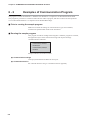
■ Running the sample program
This program is used for reading and writing data. When the program is executed,
the application layers of the instruction message and response message
communicated are indicated.
command:RS,1000W,2
result:00,0,0
command:WS,1000W,2
result:00
Sample indication of execution results
● Communication settings
Call open() and initialize the RS-232C serial port.
● Command execution
Set a desired character string in "command" and call AppCPL().
6-2
Chapter 6. COMMUNICATIN PROGRAM FOR MASTER STATION
■ Data read/write sample program
Handling Precautions
Yamatake assumes no responsiblity with regard to any trouble caused by
using this program.
6-3
Chapter 6. COMMUNICATIN PROGRAM FOR MASTER STATION
6-4
Chapter 6. COMMUNICATIN PROGRAM FOR MASTER STATION
6-5
Chapter 6. COMMUNICATIN PROGRAM FOR MASTER STATION
6-6
Chapter 6. COMMUNICATIN PROGRAM FOR MASTER STATION
6-7
Chapter 7.
TROUBLESHOOTING
■ Check items in case communication is disabled
(1) Check the power supply.
(2) Check the wiring.
(3) Check if the communication conditions for the MPC series meet those for the
host computer.
If any one of the following setting items is different between both stations,
communication is disabled:
The underlined items mean that they can be set on the MPC series side.
Transmission speed : 2400, 4800, 9600, 19200, 38400bps
Data length
: 7, 8 bits
Parity
: No parity, odd parity, even parity
Stop bit
: 1 stop bit, 2 stop bits
(4) Check if the destination address of the command frame transmitted from the
host computer meets the address set to the MPC series.
The address of the MPC series set to "0" for factory setting.
Even when the destination address of the command frame is set to 00 (30H,
30H), the MPC series does not respond to such a message.
(5) Are those multi-dropped MPC series being operated themselves with different
station address setups?
(6) Is the communication timing conformed with the 4-7 Timing Specifications
(Page 4-13) specifications?
(7) Use the capital letter character codes for all the character codes other than the
device ID code ("X" or "x" in this instrument).
7-1
Chapter 8.
SPECIFICATIONS
■ RS-485 specifications
Item
Remarks
Transmission mode
Balanced
Transmission line
3-wire system
Transmission speed (bps)
2400, 4800, 9600, 19200, 38400
Transmission distance
500m max.
(300m when connected with the MA500DIM and CMC410.)
Communications flow
Half duplex
Synchronization
Start-stop synchronization
Data format
8 data bits, 1 stop bit, even parity
8 data bits, 2 stop bits, no parity
Error detection
Parity check, checksum
Station address
0 to 127
(Communication function is inhibited when set to "0".)
Network type
1: N
(31 units or less)
Other items
Conforms to RS-485 interface specifications.
8-1
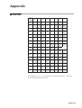
Appendix
■ Code table
UPPER
2
3
4
5
6
7
0
SPACE
0
@
P
`
p
1
!
1
A
Q
a
q
LOWER
0
1
2
STX
"
2
B
R
b
r
3
ETX
#
3
C
S
c
s
4
$
4
D
T
d
t
5
%
5
E
U
e
u
6
&
6
F
V
f
v
7
'
7
G
W
g
w
8
(
8
H
X
h
xx
9
)
9
I
Y
i
y
*
:
J
Z
j
z
B
+
;
K
[
k
{
C
,
<
L
\
l
|
-
=
M
]
m
}
E
.
>
N
^
n
~
F
/
?
O
_
o
^
A
D
LF
CR
The shaded part (
) is not used for this communication system. (The codes
to be used change every instrument.)
Appendix-1
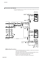
Appendix
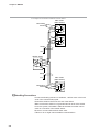
■ Connection with CMC10L
The following diagram shows an example of wiring using a straight cable for a host
computer in the terminal mode:
MPC series
(slave station)
Terminating
resistor
DA
DB
SG
Shielded
cable
RD
SD
DA
MOD.
2
2
3
3
FG
DB
TER.
MOD.
SG
TER.
RS
CS
DR
SG
ER
CD
7
7
8
8
6
6
5
5
4
4
1
1
Shielded
cable
MPC series
(slave station)
DA
DB
SG
FG
Shielded
cable
Host computer
CMC10L
MPC series
(slave station)
DA
Terminating
resistor
DB
SG
FG
Handling Precautions
• Connect terminating resistors of 150Ω±5%, 1/2W or more to the both
ends of the communication path.
• Ground the shield to the FG at one end of the shield. Make sure that
the shield is not grounded ato both ends of the shield.
• Be sure to connect SG terminals each other.
Failure to do so might cause unstable communications.
Appendix-2
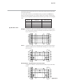
Appendix
Connect the master station SD to the slave station RD, and the master station RD
to the slave station SD.
To execute this connection, set the MODE switch provided in the CMC10L as
shown in the following table in accordance with the host computer side RS-232C
connector pin arrangement (modem/terminal) and the type of cable (cross/straight)
used:
RS-232C
Cable type
TERMINAL
Straight
MODE switch
MODEM
TERMINAL
Cross
TERMINAL
MODEM
Straight
TERMINAL
MODEM
Cross
MODEM
● RS-232C cable
Straight: An RS-232C cable with a D-SUB (9-pin) connector at each end where
pins with the same number are mutually connected (for example, pin 2
to pin 2, and pin 3 to pin 3)
CD
RD
SD
ER
SG
DR
RS
CS
Cross:
1
2
3
4
5
6
7
8
1
2
3
4
5
6
7
8
CD
RD
SD
ER
SG
DR
RS
CS
An RS-232C cable with a D-SUB (9-pin) connector at each end where
different number pins are connected (for example, pin 2 to pin 3, and
pin 3 to pin 2)
RD
SD
RS
CS
DR
ER
CD
SG
2
3
7
8
6
4
1
5
2
3
7
8
6
4
1
5
RD
SD
RS
CS
DR
ER
CD
SG
D-Sub (25-pin) – D-Sub (9-pin) conversion cable:
An RS-232C cable for conversion between D-Sub (25-pin) and D-Sub
(9-pin)
FG
SD
RD
RS
CS
DR
ER
CD
SG
1
2
3
4
5
6
20
8
7
3
2
7
8
6
4
1
5
SD
RD
RS
CS
DR
ER
CD
SG
Appendix-3
Revision History
Printed
Date
Manual Number
Edition
04-04
CP-SP-1154E 1st Edition
Revised pages
Description
Specifications are subject to change without notice.
Advanced Automation Company
Totate International Building
2-12-19 Shibuya Shibuya-ku
Tokyo 150-8316 Japan
URL: http://www.yamatake.com
This has been printed on recycled paper.
Printed in Japan.
1st Edition: Issued in Apr., 2004(E)
(02)