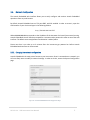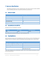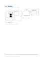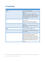
1
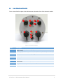
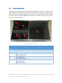
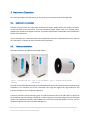
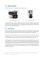
11/26/2014
VSR Instrument User
Manual
LR Tech inc.
Andre Lanouette
Revision 1
Table of Contents
1.
Introduction ...............................................................................................................................1
2.
Packing and Visual Inspection .....................................................................................................2
3.
4.
5.
2.1.
Front View of the VSR ................................................................................................................... 2
2.2.
Rear View of the VSR .................................................................................................................... 3
2.3.
Front Plate View of the VSR .......................................................................................................... 4
2.4.
Transport Case Layout .................................................................................................................. 5
Instrument Operation .................................................................................................................6
3.1.
Instrument connections ................................................................................................................ 6
3.2.
Telescope Installation ................................................................................................................... 6
3.3.
Cold Source Installation ................................................................................................................ 7
3.4.
Startup Sequence .......................................................................................................................... 7
3.5.
Network Configuration ................................................................................................................. 8
3.5.1.
Changing the network configuration .................................................................................... 8
3.5.2.
Reset your network settings to defaults ............................................................................... 9
Instrument Maintenance .......................................................................................................... 10
4.1.
General Care ............................................................................................................................... 10
4.2.
Telescope Care ............................................................................................................................ 10
4.3.
Hygroscopic Materials Notice ..................................................................................................... 11
Instrument Specifications ......................................................................................................... 12
5.1.
Instrument Weight ...................................................................................................................... 12
5.2.
Expected Components Life Time ................................................................................................ 12
5.3.
Power Specifications ................................................................................................................... 12
5.4.
Dimensions.................................................................................................................................. 13
6.
Troubleshooting ....................................................................................................................... 14
7.
Document Revisions ................................................................................................................. 15
1. Introduction
This manual is intended to be used by instrument operators as a complement to the formation given by
trained LR Tech personnel. It provides basic information on the operation and maintenance of the LR Tech
Versatile Spectro-Radiometer (VSR).
The Versatile Spectro-Radiometer (VSR) is a compact high sensitivity Spectro-Radiometer which uses
Fourier Transform Infrared (FT-IR) technology. Its high speed, yet robust operation allows it to be used in
different scenarios, from laboratory usage to airborne and heavy vibrations environments. The VSR can
provide real-time high resolution spectral information on slow and fast occurring phenomenon, as well as
perform material and target signature analysis.
A large range of optional accessories are offered with the VSR instrument, allowing you to get the right
configuration for your demanding application. 3 different telescope options are available; wide field-ofview, medium field-of-view and narrow field-of-view. Additionally, 2 different configurations of cold
subtraction sources are offered to maximize the contrast. A bore siding camera is available to help you
point the instrument to remote targets.
LR Tech Inc. VSR Instrument User Manual
1
2. Packing and Visual Inspection
2.1.
Front View of the VSR
This is a view of the front side of the VSR instrument. Connections are made on this side of the
instrument. The power supply block is removable and can be relocated from the instrument.
Figure 1 - Front view of the VSR
Item #
1
2
3
4
5
6
Description
Cold subtraction source.
Optical module. Contains the instrument modulator and detectors.
External heat sinks. Help keep the instrument stable in temperature.
Power supply. Provide power when not operating on airborne platforms.
Optical module access purge.
Electronic module. Contains all the electronics of the instrument.
LR Tech Inc. VSR Instrument User Manual
2
2.2.
Rear View of the VSR
This is a view of the rear of the VSR instrument, facing the target it is currently observing.
Telescope and additional optics are installed on this side of the instrument.
Figure 2 - Rear view of the VSR
Item #
1
2
3
4
Description
Electronic module. Contains most electronics of the instrument.
Electronic module air intake. Used to keep the instrument electronics cool.
Bore siding camera.
Entrance port.
LR Tech Inc. VSR Instrument User Manual
3
2.3.
Front Plate View of the VSR
This is a view of the front plate of the VSR instrument, located in front of the electronic module.
Figure 3 - Instrument Front Plate
Item #
1
2
3
4
5
6
7
8
9
10
11
Description
24V power input (from power supply provided with instrument or external
power source)
Auxiliary power for instrument accessories (cold source, blackbody controller)
Reset switch for network factory settings
Green “Powered On” LED
Blue “Ready” LED
On/Off push button switch
USB connector for external USB accessories
GPS Antenna
Remote start switch to control local data acquisition
7 Amps fuse
Ethernet connection for network access
LR Tech Inc. VSR Instrument User Manual
4
2.4.
Transport Case Layout
Careful attention should always be brought when packaging the instrument for shipment over
long distances. The VSR instrument is composed of various optical systems, sensible to shocks,
which may break the optical alignment of the system. You should always use the provided
transport case with sufficient packaging to prevent the instrument and its accessories from
bouncing in the transport case.
Figure 4 - VSR Transport Case Layout
Item #
Description
1
2
3
4
Power supply
Cables
Narrow-angle telescope
Medium-angle telescope
Wide-angle telescope
Bore siding camera
Cold subtraction sources
VSR instrument
Acquisition laptop
Gold reference plate
5
6
LR Tech Inc. VSR Instrument User Manual
5
3. Instrument Operation
This section provides basic information on how to get your instrument up and running quickly.
3.1.
Instrument connections
The VSR is easy to install. You simply need to connect the power supply cable to the “Power” connector
on the front plate of the instrument. If you use an external power supply, such as an airplane power,
provide clean 24-28V to the power connector. Full power specifications are available in the specifications
section of this document.
If your instrument has a cold subtraction source attached, connect the cold subtraction source cable to
the “Aux power” connector on the front plate of the instrument.
3.2.
Telescope Installation
The VSR instrument has 3 different telescope options:
Figure 5 – TEL-100M Wide FOV
Telescope
Figure 6 – TEL-37M Medium
FOV Telescope
Figure 7 – TEL-5M Narrow FOV Telescope
The wide and medium FOV telescopes are installed the same way on the VSR. Push the telescope opening
completely in the entrance port of the instrument, then align and tighten the ring attached to the
instrument. Make sure it is completely tightened.
In order to install the narrow telescope, push it inside the entrance port of the VSR. Hold it at level with
the instrument and start rotating it clockwise. In order to get the correct optical alignment, the telescope
needs to be completely screwed in place. Make sure you hold the telescope weight at all time until it is
completely tightened in order to prevent damage to it.
LR Tech Inc. VSR Instrument User Manual
6
3.3.
Cold Source Installation
The VSR instrument has 2 different cold subtraction source options:
Figure 8 - SSP-273 - Cold subtraction source based on a
thermo-electric cooler
Figure 9 - SSP-77K - Cold subtraction source based on a
stirling cooler (LN2 free)
All cold subtraction source models manufactured by LR Tech for the VSR uses the same mounting
mechanism. Simply insert the cold source in the cold source port located on top of the instrument. Then
screw in place the 2 screws that tighten the ring on the base of the cold subtraction source. Connect and
secure in place the power connector [BD9].
3.4.
Startup Sequence
Make sure your instrument is connected properly and that it receives clean power to its power supply.
Turn on the instrument by pushing the push-button switch on the front plate of the electronic box. When
power is correctly applied to the instrument and it is turned on, the green LED “On” should be lit.
After a few seconds, the blue “Ready” LED should start flashing rapidly, while the electronics of the VSR
are powering up. Soon after, the blue “Ready” LED should start flashing slower, while the software
“Anneth Embedded” is getting ready to receive a connection from Edgar or to acquire data locally.
Once the instrument is fully powered up and ready, the blue “Ready” LED should become solid. As soon
as the ready LED is on, you can connect to the instrument using the Edgar software or you can start
acquiring data locally on it. However, to get the maximal radiometric accuracy out of your VSR instrument,
we strongly recommend that you let the temperature of the instrument stabilize before starting to acquire
data. Depending on the environment where you operate your instrument, the temperature stabilization
time may vary. In laboratory condition, you can expect around 30 – 45 minutes to get the instrument
stabilized in temperature.
LR Tech Inc. VSR Instrument User Manual
7
3.5.
Network Configuration
The Anneth Embedded web interface allows you to easily configure and monitor Anneth Embedded
operations from any web browser.
By default, Anneth Embedded runs on TCP port 8585, with SSL enabled. In order to access it, open the
web browser of your choice and type in the following address
https://###.###.###.###:8585
Where ###.###.###.### corresponds to the IP address of the Annotator Pro board (instrument) running.
Anneth Embedded. You will then be prompted for a username and a password in order to access the web
interface. The default username/password combination is admin/admin.
Please note that it can take up to 3 minutes after the instrument got powered on before Anneth
Embedded web interface can be accessed.
3.5.1. Changing the network configuration
Anneth Embedded is the main point of access to your instrument. Since it is accessed over a network, you
will most likely want to modify its network settings. In order to do this, access the System Configuration
page.
Figure 10 - Anneth Embedded Network Configuration Page
LR Tech Inc. VSR Instrument User Manual
8
The top section of this page displays the settings currently applied to your instrument. In order to obtain
a dynamic IP address from your router, select the DHCP option. Otherwise, select the static IP address
option and fill in the required field. If you press the “Save” option, your settings will be saved, but will only
be applied after a restart of the instrument. If you press the “Save and apply option”, the board will
automatically restart, and the new network settings will be applied right away. Make sure to adjust the
address of the web interface in your web browser according to the new settings you entered.
3.5.2. Reset your network settings to defaults
If you forgot the IP address that was assigned to the instrument, most instruments come equipped with
a “Factory Reset” button. If you press and hold this button for 10 seconds, you will see the “Annotator
Ready” light begin to flash rapidly. After a few seconds, the board will be restarted and default settings
will be applied (network configuration and username/password. The default network configuration are:
Hostname
ANNOTATORPRO
IP Address
192.168.0.100
Netmask
255.255.255.0
Gateway
192.168.0.1
Username
admin
Password
admin
LR Tech Inc. VSR Instrument User Manual
9
4. Instrument Maintenance
4.1.
General Care
There are no user serviceable parts inside the Versatile Spectro-radiometer. The VSR spectrometer should
be opened only by trained and authorized personnel.
DANGER: High voltage inside, 6.5 kV at start-up and 1400 V steady operation. Due to capacitance effect
the high voltage may be present while the instrument is powered off.
The VSR spectrometer is designed for indoor and outdoor use, but it should not be exposed to excessive
moisture, rain and dust.
VSR spectrometers are built with durable urethane paint and anodized aluminum. It can be cleaned with
soft soap in water.
4.2.
Telescope Care
Protect telescope and its optics by using bags and protective covers provided with the instrument. Never
touch optical components; windows, mirrors or lens surfaces with bare hands. Use dust free gloves for
critical manipulation and cleaning.
Contaminant
Dust
Fingerprints
Dirt particles
Cleaning method
Dust contaminant can usually be removed using pressurized gas
Fingerprints on a coated lens should be cleaned as soon as possible to avoid
staining or damaging the optic
Should be removed with a dust-free blower before attempting to clean the
optic with tissue or cotton
The following procedure can be used for cleaning coated ZnSe lens and bare aluminum mirror:
1. Dirt particles should be removed with a dust-free blower before attempting to clean the optic
with tissue or cotton
2. Used soft lens tissue or cotton with acetone to remove dirt and finish it with isopropyl alcohol to
eliminate streaks or residue.
3. Dry off excess of liquid
LR Tech Inc. VSR Instrument User Manual
10
Take note that bare aluminum mirror is soft. Make a test of the tissue used to clean on a small area to
make sure not to scratch the surface.
4.3.
Hygroscopic Materials Notice
If the beam splitter of your VSR is made from KBr material, follow this section attentively. This is a popular
material used in IR spectroscopy because of its spectral coverage characteristics. KBr is hygroscopic and
must be manipulated and store with special care. It withstands thermal and mechanical shock well, but
must not be cleaned with aqueous solvent, glycerol, the lower alcohols or stored in a high level of humidity
environment. Inside the sealed interferometer module with fresh desiccant, the KBR is well protected.
Desiccant inside the cartridge must be replaced every year or if indicators, 1-wire housekeeping humidity
sensor or colored dots, show internal humidity of 30% or higher. The Interferometer module (Gold finish
or stainless steel cylinder module) most only be opened by authorized and trained personnel. Mishandling
of hygroscopic material may results in severe damage of the instrument. Under the proper conditions KBR
beam splitter will maintain its integrity for several year without any problems.
LR Tech Inc. VSR Instrument User Manual
11
5. Instrument Specifications
The following specifications are for the standard version of the VSR. If you have a custom modified
version of the VSR, please refer to the specific specifications provided to you.
5.1.
Instrument Weight
Component
VSR Instrument
Cold Source
Wide FOV Telescope
Medium FOV Telescope
Narrow FOV Telescope
Tripod (With head)
Transport Case for VSR Instrument
Transport Case for Tripod
5.2.
Weight (Kg)
21
1
1
3.2
7
16
48
23
Expected Components Life Time
Components life time listed below are estimates.
Component
Shelf at 25°C
Operational at 25°C
Laser
7 years
5 years
Sterling Cooler
4 years
20,000 hours
Note: Sterling cooler operational life time for a cooler operating at 77°K.
5.3.
Power Specifications
Power Specifications below are for the standard version of the VSR. If your version of the VSR has built-in
calibration sources or accessories, consult the specification sheets provided to you or contact LR Tech.
Specification
External power supply input voltage
External power supply frequency range
Output power rating
Output voltage channel 1
Output current channel 1
VSR with cold source current
Value
100-240 VAC 4.0A
50 to 60Hz
240W
24VDC
10A Max
4.0 A @ 24 VDC Max
3.4 A @ 24 VDC Typical
If you use the VSR without the provided power supply, contact LR Tech to get the input power connector
pin out and specifications.
LR Tech Inc. VSR Instrument User Manual
12
5.4.
Dimensions
Figure 12 - VSR lateral view
Figure 11- VSR view from above the instrument
LR Tech Inc. VSR Instrument User Manual
13
6. Troubleshooting
Issue
Anneth Embedded Web interface does not
respond
Edgar cannot connect to Anneth Embedded
One of the device does not respond
Edgar cannot communicate with one of the
devices
Local capture mode reports that the disk is full
Some scans are being skipped in the data
LR Tech Inc. VSR Instrument User Manual
Solution
Make sure the board is powered on and
connected to your network;
Make sure the Annotator Ready Led is on and not
flashing;
Attempt to do a “ping” command to the IP
address of the board. If it responds, then attempt
power cycling the board. If it doesn’t respond,
revert to factory IP and reconfigure the board
network settings.
Make sure Anneth Embedded is in “Remote
Connect Mode”;
Make sure every devices are “Waiting for
connections” from the “Current status” page
Make sure the corresponding device is connected
physically;
Make sure the correct RS232 port is defined for
the given device.
Make sure the network TCP port defined in
Anneth Embedded and Edgar match.
Make some room on the hard drive by
connecting to the network share and deleting
some data files.
Verify that your instrument configuration sets
support the specifications of your instrument
(speed, resolution, laser frequency);
Verify the load average from the local capture
mode “Current Status” page. If it is above 2.0,
make sure you are not connected to the network
share during the acquisition of your data. The
network share can cause heavy loads on your
system.
14
7. Document Revisions
The table below illustrate the different revisions of this manual.
Revision
Date
Author
1
2014/11/26
André Lanouette
LR Tech Inc. VSR Instrument User Manual
15