1
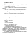
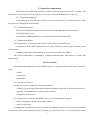
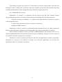
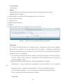
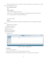
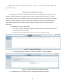
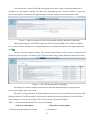
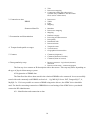
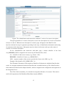
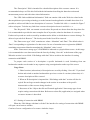
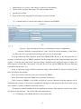
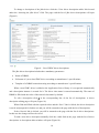
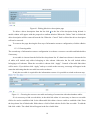
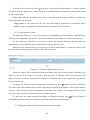
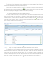
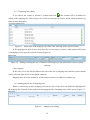
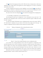
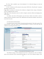
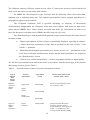
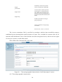
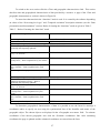
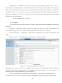
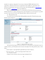
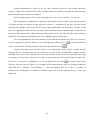
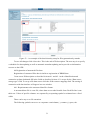
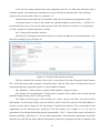
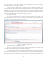
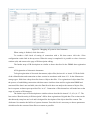
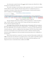
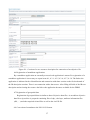
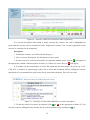
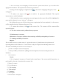
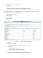
DATA PROVIDER. USER MANUAL (V.2.1) 2013 CONTENTS 1 Introduction.............................................................................................................................................. 3 1.1 Purpose of the document..................................................................................................................... 3 1.2 Overview of the document.................................................................................................................. 3 1.3 Terms and definitions ......................................................................................................................... 4 2.1 Purpose................................................................................................................................................ 6 2.2 Composition of components ............................................................................................................... 6 2.3 Operation requirements ................................................................................................................... 7 2.3.1 Computing equipment.................................................................................................................. 7 2.3.2 Telecommunications .................................................................................................................... 7 2.3.3 Institutional support ..................................................................................................................... 7 2.4. Process flow ...................................................................................................................................... 7 2.4.1. Design of resources......................................................................................................................... 7 2.4.2. Registration of resources............................................................................................................. 8 2.4.3. Maintenance of resources............................................................................................................ 9 3 User interface.......................................................................................................................................... 10 3.1 Main page.......................................................................................................................................... 10 3.2 Operator’s WKS................................................................................................................................ 11 4 Registration of information resources.................................................................................................. 12 4.1 Registration of a new IR description................................................................................................. 12 4.2 Registration of a new IR description by importing the existing description ................................... 12 4.3 Registration of DBMS data............................................................................................................... 14 4.3.1 Identification and connection to data ......................................................................................... 14 4.3.2 Setting of connection with DBMS ............................................................................................. 16 4.3.4 Presentation and dissemination.................................................................................................. 24 4.3.5 Time and geographic characteristics.......................................................................................... 26 4.3.6 Contacts...................................................................................................................................... 28 4.3.7 Data granularity setup ................................................................................................................ 29 4.4 Registration of structured files data. ................................................................................................. 31 4.4.1 Requirements to the structured data files format. ...................................................................... 31 4.4.2. Setting of the data files structure............................................................................................... 32 4.4.3 Data source setting ..................................................................................................................... 33 4.4.4 Mapping ..................................................................................................................................... 34 4.5 Registration of electronic documents................................................................................................ 35 4.6 Registration of standalone applications ............................................................................................ 37 4.7 Registration of geospatial data.......................................................................................................... 37 4.8 Conversion of metadata to the ISO 19139 format. ........................................................................... 37 5 Resource management........................................................................................................................... 38 5.1 Registration of resources................................................................................................................... 38 5.2 Maintenance of resources.................................................................................................................. 40 5.3 Assuring availability of resources..................................................................................................... 40 6 Access to the auxiliary information...................................................................................................... 43 6.1 Codes................................................................................................................................................. 43 6.2 Dictionaries ....................................................................................................................................... 44 6.3 Data elements.................................................................................................................................... 44 2 1 Introduction 1.1 Purpose of the document The IODE Ocean Data Portal (ODP) delivers a standards-based infrastructure for integration of marine data and services submitted by the NODCs, data centers (institutions) of IOC and other programmes (ODP participants), as well as for data discovery, evaluation (through visualization and metadata review) and access to them. The ODP participants provide the operations of the global, regional/specialized, technical and national nodes. The ODP v2 toolkit is available to set up the ODP node by participants based upon the designated participant role and functionality required. The Data Provider is a component of the toolkit for submission of the data and services (resources) to the ODP distributed marine data system (DMDS) and their management. The Data Provider is used by the ODP nodes of all categories. The ODP participant can use the Data Provider, installed at its own server or available at another ODP node. The purpose of the document is to describe the process of using the Data Provider for registration and maintenance of the ODP DMDS resources. The document is intended for the staff of the IODE National Oceanographic Data Centres (NODCs) and other institutions responsible for maintaining an ODP node and providing data and services to the ODP (hereinafter referred to as “Centre”). The document is developed by the Partnership Centre for the IODE ODP (National Oceanographic Data Centre (NODC), Research Institute of Hydrometeorological Information – World Data Centre (RIHMI-WDC), Federal Service for Hydrometeorology and Environmental Monitoring (Roshydromet), Russian Federation. 1.2 Overview of the document The document includes the following sections: Section 1 - Introduction Section 2 – Conditions of application – The purpose and components of the Data Provider are considered as well as requirements mandatory for the Data Provider operation. Section 3 – User interface – The main page of the Data Provider user interface is described and information on its main sections is given. Section 4 - Description of a new resource – The rules and procedures of describing new ODP resource developed by Centre on the basis of its local data and with the aid of the Data Provider Webforms. 3 Section 5 – Resource management – The process of registration and maintenance of the ODP resources by Center is described. Section 6 – Access to auxiliary information – Instructions on how to access system codes, dictionaries and descriptions of data elements (dictionary of parameters) used to manage the ODP resources are given. Annex 1 – The Guide on describing a resource with the aid of the Data Provider Web-forms is provided. 1.3 Terms and definitions Ocean Data Portal (ODP) is a standards-based distributed infrastructure to facilitate and promote the exchange and dissemination of marine data and services for all IOC and related international programmes ODP node: the core ODP element providing access to data and services contributed by the host data centre and (or) by other nodes, interaction and exchange with other nodes, and on-line access to the data and services associated with the given node or (and) with another node. It can be global, regional, specialized, national (data provider) or technical. ODP participant: IODE NODCs or other IOC and non-IOC projects/programmes participant that deal directly with the marine data and service management and operate as an ODP node. It can simultaneously provide the operation of the two nodes– global (or regional/specialize/technical) and national nodes. Code: names of objects and their features (properties), code values of objects in the form of sequence of characters used for unambiguous understanding of data. Data: reinterpretable representation of information in a formalized manner suitable for communication, interpretation, or processing Dataset: identifiable collection of data sharing the same product specification Data element: atomic portion of data with specific properties (code, name, units of measurements, data type, etc). Data elements can be: − metadata (information on data – identifiers of country, organization, platform; time period, spatial coverage, etc); − values of marine environment parameters. The Data Provider performs mapping of local data elements into system data elements assuring data unification. Data exchange protocol – agreements regulating data exchange between the Data Provider and the Integration Server. Data exchange protocol consists of a request-message, response-message and transport data file. Data Provider: the ODP Tools component for interfaces with data sources (SQL databases, data file systems, applications, HTTP, FTP-inventories) connected with the ODP node, creation and update of the discovery metadata about data/services, access to metadata and data for integrated use on the predefined time schedule and update events; 4 Dictionaries: codes and structured descriptions of objects (organizations, ships, buoys, satellites, etc.). System dictionaries are used for the unification of data coding by mapping local codes into system codes. Distributed marine data system: a set of resources, managed by the Integration Server of the ODP node (global, regional or specialized). Interoperability: possibility for [spatial] data sets to be combined, and for services to interact, without repetitive manual intervention. Integration Server - the ODP Tools component for metadata harvesting (event-based) and data download from the connected nodes through the Data Provider, metadata synchronization and data exchange between the nodes, consolidation of metadata catalogs at the global node, interfaces with external systems and applications; Metadata: information describing data sets and services and making it possible to discover, inventory and use them. Product: a value-added enhancement of data applied to a particular application. Resource: asset or means that fulfills a requirement. The ODP resource is a data/service submitted into DMDS using ODP tool kit or basing on relevant interoperability arrangements. Resource has a unique identifier and can consist of structural units – resource instances. The content and structure of resource are recorded in metadata when resource is described Service: distinct part of the functionality that is provided by an entity through interfaces Transport data file: the data set provided by a node in response to the request from the Integration Server or according to data updating schedule or event. 1.4. Contact information. Sergey V. Sukhonosov, tel.: (48439) 74194, fax: (495) 2552225, E-mail [email protected] Sergey V. Belov, tel.: (48439) 74194, fax: (495) 2552225, E-mail [email protected] Kristina V. Bulgakova, tel.: (48439) 74194, fax: (495) 2552225, E-mail [email protected] 1.5 References. 1. E2EDM User's Manual v.1.0 (Updated 15 Jan 2007) 2. E2EDM Data Provider User Guide (version 1.1.0, September 2007). Installation and setup. 3. E2EDM Overview v.1.0 (March 2007) 4. E2EDM Technology Implementation v.1.0 (March 2007) 5. E2EDM Technical Specifications v.1.0 (Updated 15 Jun 2006) 6. E2EDM Concept XML Scheme v.1.0 (Updated 15 Jan 2007) 7. E2EDM Global XML Scheme v.1.0 (Updated 15 Jan 2007) 5 2 CONDITIONS OF APPLICATION 2.1 Purpose The Data Provider software is an ODP technology component responsible for integration of information resources and performing the following functions of the ODP data source: − connection to the local data sets of Centre; − generation and updating of resource descriptions in compliance with the current status of the local data set; − data sampling on request of the Integration Server, structural and code unification of data, transport data file formation as a response to the request; - monitoring of the Data Provider software and registered resources performance on the basis of the current status information generated by the software itself. The Data Provider provides interaction with the following types of data storage systems: − DBMS database; − structured data files in “flat” (non-hierarchical) data formats; − object data files: electronic documents, images, structured data files in formats, which are not handled by the ODP technology software; − Web-applications performing an access to the local data sets; 2.2 Composition of components The Data Provider software includes: − J2SDK v.1.7; − Data Provider configuration library; − Data Provider web-module. The Data Provider software implements user interface for: − technical support of the Data Provider in Centres; − registration and maintenance of the DMDS resources provided by Centres. In this document the use of the Data Provider (DP) user interface for registration and maintenance of the DDSS resources in Centre is considered. The interface consists of a set of pages containing Webforms and other tools of description, viewing, editing, etc and is available through the Web-browser at the address given to Centre with the installation of the Data Provider [1, 2]. This guide is the main document on the use of the Data Provider. In addition it is recommended to use other documents of the E2EDM technology [1-5]. 6 2.3 Operation requirements The Data Provider (DP) user interface is initiated by the web-browser from PC of Centre. The DP software as such is located on a separate server in the telecommunication hub of Centre [2]. 2.3.1 Computing equipment In the general case the DP user interface can be used from any PC connected with the Data Provider server through the local network. 2.3.2 Telecommunications PC used for the DP user interface should be connected through the local network with: − the Data Provider server; − local data sets: DBMS databases, sets of structured and objective data files. 2.3.3 Institutional support The Data Provider is operated by the staff of Centre. They are responsible for: − interaction with the ODP Administrator on issues related to system codes, dictionaries and data elements; − planning, registration and maintenance of resources provided to the DDSS. The overall coordination is performed by a dedicated staff member, who works as a Centre data administrator. 2.4. Process flow Registration and maintenance of the DDSS resources is performed by the following consecutive steps: − design; − registration; − maintenance. 2.4.1. Design of resources Design of resources includes the following operations: − refining of system codes, dictionaries and data elements on the basis of the local data analysis; − mapping of local and system codes and data elements; − configuration of resources. For each data sets provided as the DDSS resource it is recommended to prepare; − table of mapping local and system data elements; − table of local codes. Configuration of information resources consists in making decisions on the content and structure of resources. Data provider can present the local data set in the form of one or several resources on the 7 basis of time (data for specific periods), geographical location (data for specific regions) and other characteristics. Each resource can be presented in the form of one or several instances, as well as without segmentation into instances. To design resources of one data set a 1-2-week work of one staff member of Centre is required. Additional time is needed to refine (extend) system information. The outcomes of design are registered in the form of a working document and further registration and maintenance of Centre’s resources are performed in accordance with this working document. Usage note. The above working document offers significant time savings and makes registration and maintenance of resources easier. 2.4.2. Registration of resources Registration of resources includes: − resource description; − resource setup. 2.4.2.1 Resource description is made with the help of the DP User Interface (menu: Operator/New resource description, Section 4 of this document). The User Interface includes a set of bookmarks containing Web-forms for resource description on a section-by-section basis. If Web-forms of the “Identification and connection to data” section are filled in properly, resource gains a status of a “resource under registration”, i.e. it is in the process of registration. To reduce work efforts it is recommended to use descriptions of resources prepared in advance in the form of description templates. 2.4.2.2 Resource setup is made with the help of the DP User Interface (menu: Operator/Registered resources, Section 5 of this document) and includes: − setup of mapping local codes into system codes; − setup of periodicity of automatic updating of description of resources and generation of instances; − testing and quality check of resources Along with the above operations description of resources is refined on the basis of error and comment reports. When registration is finalized resource gains a status of a “registered resource”, i.e. it becomes operational. Registration of resources is performed by the Centre data administrator. 8 Time needed to register one resource is 3-5 hours (the first resource) and less than 1 hour (the next following resources taking into account the experience gained) provided that this document has been carefully studied and the resource design has been performed on a high-quality level. 2.4.3. Maintenance of resources Maintenance of resources is performed with the help of the DP User Interface (menu: Operator/Registered resources, Section 5 of this document) and includes the following operations: − assurance of resources availability, i.e. readiness of the Data Provider to response to requests of the Integration Server; − re-setup of the content and structure of resources if necessary; − updating of DDSS resources. Monitoring of Centre’s resources is performed by the Integration Server [4], which controls the Data Provider performance indicators such as preparedness for connection and status of resources. Efforts needed to maintain resources provided by DBMS databases and structured files are very small. In standard situations only a periodic check of resource availabilityy, change in resources setup, etc are required. Any other operations are not needed. Extension of resources consisting of objective data files and applications is made by preparing a description of a resource’s new instance to include a new data file (application). For one data file (application) about 10-15 minutes are required. 9 3 User interface 3.1 Main page Purpose To choose Data Provider (DP) functions and switch to relevant sections of the menu Layout as shown in Figure1 1 – interface header, switch to the ODP technology Web-site, current data, 2 –sections of the main menu, 3 –explanatory text, 4 –login/password of DP users, 5 –feedback, 6- identifier of ODP Centre, date of updating and version of the DP. Figure 1 - General view of the Data Provider user interface Description 1. To start the Data Provide user interface open a Web-browser and enter the address http://<IP_server_ address>:<server_port>/dpms (IP_server_address – IP address provided when the DP was installed and set up; default server port is 8080 or the one provided when the JBoss Application Server was installed). 2. After entering the address the DP user interface main page will appear as shown in Figure1. Click the “Login” link to make user authorization. On the appeared page enter login and password and click “Login”. At the top of the page in the main menu the following bookmarks are available: − Administrator – setup of application, management of system schedulers, view of workflow log; − Metadata operator - registration and maintenance of Centre’s information resources; − Codes, Parameter dictionary – access to system codes, dictionaries and data elements; − Help –copying of this and other documents, feedback. Usage notes 10 The access address for the User Interface, login and password are provided when the Data Provider is installed in your Centre Error (comment) report None Alarm conditions 1. The user interface page is not started. Probable cause – settings have been changed or the DP Application Server does not function Actions: update the page, contact the DP administrator 3.2 Operator’s WKS Purpose Registration and maintenance of ODP Centre’s information resources submitted to the unified system Layout as shown in Figure2 1 – WKS hierarchical menu Management of resources: Registered resources Resources under registration New resource description 2 - –explanatory text Figure2 – Operator’s WKS interface Description − Choose section of the menu: − New resource description – if it is planned to add a new resource − Management of resources/Resource under registration – to continue resource registration 11 − Management of resources/Registered resource – to refine a description or change settings of the operational resource. 4 Registration of information resources Registration of IR is made using the Data Provider interface and includes a sequence of steps needed to create IR description (metadata) and to connect it to data from a data source. There are different types of data sources: DBMS, structured files, standalone applications, electronic documents, images, GIS-layers and other types of files which are not directly processed by the Data Provider. Regarding the connection to the IR description, each type of data sources has its own rules and procedures. 4.1 Registration of a new IR description 1) To register a new IR description click the “Metadata operator” link in the main menu of the Data Provider user interface 2) In the menu on the left click the “Create new resource description” link. Figure 3 – Operator’s WKS page 3) On the appeared page click the “Create new description” to start registration Figure 4 – Page of creation of a new IR description 4.2 Registration of a new IR description by importing the existing description 12 To accelerate the creation of new IR descriptions on the basis of the existing descriptions it is possible to use the “Import” function. For that in the “Metadata operator” interface click the “Create new resource description” link and on the appeared page click the “Import resource description” link. Figure 5 - Page of creation of a new IR description using the function of importing” On the appeared page a list of IR descriptions will be provided which can be used as a template for creation of a new description. For importing choose the required description in the right column and click . Choose a resource template taking into account characteristics of the resource, a description of which you plan to prepare. At least the type of physical data storage system should be taken into account. Figure 6 – List of IR descriptions for importing All settings of resource-template connections to data and data hierarchy are copied into the resource description, which you create. The process of registration of an IR description has two steps: the connection to a data source and filling of sections of an IR description. Each section contains subsections consisting of several fields to enter elements of a resource description. The list of sections is provided in Table 1. Table 1 – Sections and subsections of a resource description. Section of a description 1. Identification and connection to data Subsection of a description 1. Identification 13 2. Title 3. Data source mapping 4. Connection to data (this subsection is available only if DBMS or structured data file is used as a data source) 2. Connection to data DBMS Structured data file 1. 2. 3. 4. Data source Tables Filter Mapping 1. Metadata 2. Data source mapping 3. Mapping 3. Presentation and dissemination 1. 2. 3. 4. 5. 4. Temporal and spatial coverages 1. Temporal extent 2. Vertical extent 3. Geographical characteristics 5. Contacts 1. Contacts (Originator) 2. Contacts (Resource Provider) 3. Contacts (Point of contact) 6. Data granularity setup 1. Resource structure - logical unit (instance) allocation 2. Data record structure - content assignment Platform category Processing and data structure Data quality Distribution info Data restrictions The first step is to connect an IR description with a data source. This step may differ depending on the type of physical data storage system. 4.3 Registration of DBMS data The Data Provider allows data stored in the relational DBMSs to be connected. It was successfully tested with such commonly used DBMSs as Oracle 8 – 11g, MS SQL Server 2007, PostgresSQL 7, 8, MySQL 5.x. If it is not possible to connect a DBMS using native drivers, the ODBC driver should be used. For details concerning connection of DBMS drivers and setting of the ODBC driver you should contact the DP Administrator. 4.3.1 Identification and connection to data 14 Figure7 The «Identification and connection with data»” section of a resource description To begin registration of a resource description, create a new description of a resource as described in items 4.1 and 4.2. When the new description is created a page will appear in the Data Provider interface with the first step of registration providing for the entry of identification information and setting of connection with a data source. Subsequent steps are shown in the menu at the top as the names of sections of a resource description. On the «Identification and connection with data» page a unique identifier of the form AA_BBBBBBB_NNN is assigned to the resource by the Data Provider, where АА – identifier of data source country (e.g., Russia – RU); BBBBBBB – identifier of Centre (e.g., RIHMI-WDC) NNN – sequence number of the resource provided by Centre to the ODP (e.g., 38) Example of the identifier: RU_RIHMI-WDC_38 The «Thematic Federation» field contains an identifier of federation in which the Data Provider works. It is assigned automatically when the Data Provider is installed and set up. The «Data Provider» field contains the Data Provider unique identifier, which is assigned in the configuration and registered on the Integration Server. The «Title» field is mandatory. It is intended to assign the full name of a resource. This name is used in all components of the Distributed Data Bases System (DDBS). 15 The “Description” field is intended for a detailed description of the resource content. It is recommended always to fill in this field with the information describing the data observation and measurement process and with other related information. The “URL-link to additional information” field can contain a link to the Web-site related to the data acquisition or processing technology or to the Internet-based application to handle these data. It is possible to add several links for one description of a resource. To add a link click «+» marked in Figure 7 with a red square. To delete any link from a resource description choose it and click «--». The “Keywords” field can contain several values. Keywords are chosen from the drop-down list. It is recommended to provide the most complete list of keywords, related to the theme of a resource. Further on keywords are used to search by metadata and to define to which theme a resource belongs. To delete a keyword click “Remove”. The last keyword in the list will be removed. The “Data source type” field” contains two values: “Metadata” and “Data”. The default value is ‘Data” corresponding to registration of a data source. In case of metadata source registration (DBMS containing not measured data but metadata) the “Metadata” value is used. In the “Data source storage type” field DBMS is indicated as a physical data source. At this stage it is recommended to save data entered into the form by clicking “Save tab” at the bottom of the page. When the section is saved click “Edit linkage with data” link to switch to the interface for setting connection with DBMS. To prepare each section of a description a specific bookmark is used. Switching from one bookmark to another can be made in any sequence using a navigation bar at the top of the screen. Usage Notes: 1. Edited sections (subsections) of description are saved by clicking “Save tab”. If you don’t do that and switch to another bookmark the previous version of a section (subsection) of a resource description will be restored. 2. When an IR description is imported the “Edit linkage with data” section will also be copied. Do not forget to make changes in the section in accordance with specific characteristics of the resource being described. 3. Resources of the “Object data file and External application” data storage type do not require setting connection with data. References to data file (application) are assigned when a resource instance is described. 4.3.2 Setting of connection with DBMS When the “Edit linkage with data is clicked” the interface for setting of connection with DBMS will open a new browser window. Creation of a new configuration of a resource includes 4 steps. 16 1. Identification of a resource and setting of connection with database 2. Choice of the root table and setting of its link with other tables 3. Specification of filter 4. Setup of table fields mapping into information resource elements 1.3.2.1 Identification of resource and setting of connection with DBMS Figure 8 – Page showing the first step of information resource configuration A resource identifier is entered into the “Code” field. This field is mandatory. If the field is not filled, an error is reported and switching to the next step is not possible. To set up connection with a database in the field «DBMS JDBC driver» of the drop-down list it is necessary to choose the type of DBMS responsible for the management of the required database and click «Apply». Under the entry field of the connection string a template of this string will appear as a hint. If it did not appear, it means that a description of the jdbc driver for the chosen DBMS has not been filled and it should be edited (item 1.2.3). In the «Connection string» field the connection string values should be entered according to the rules specified by the template. In the «User name» field enter user name registered in DBMS. In the «Password» field enter DBMS user password (if necessary). Click «Connect to DBMS». If all fields are filled in correctly connection with the database will be established, the message «Connection is established» will appear in the status bar, the «Next» link will be active and the «Connect to DBMS» link will be inactive. If connection with the database was not established a message indicating the reason for the failure will appear in the status bar. The «Next» link will remain inactive. 1.3.2.2 Handling of the DBMS jdbc driver description table 17 To change a description of the jdbc driver click the «View driver description table» link located under the “choosing the jdbc driver” field. The page with the list of jdbc driver descriptions will open (Figure9) Figure9 – List of JDBC driver descriptions The jdbc driver description includes three mandatory parameters: • Name of DBMS; • Full name of a java-class JDBC driver according to manufacturer’s specifications; • Template of a DBMS connection string according to manufacturer’s specifications. When a new JDBC driver is added to the Application Server library it is recognized automatically and a description instance is created for it. The driver class name is entered automatically. The name of DBMS is filled with the value of the entered class name by default. To edit a description click in the corresponding line of the list of descriptions. A driver description editing page will open (Figure 10). When fields and filled with the required values and the “Save” link is clicked, the driver description is saved and prepared for further use and you will be returned to the page with the list of descriptions. If the «Cancel» link is clicked, you will be returned to the page with the list of driver descriptions. In this case the changes will not be saved. To add a new driver description manually click the «Add» link on the page with the list of driver descriptions. A description editor window will open (Figure10). 18 Figure10 - Editing jdbs driver description page To delete a driver description from the list click in the line of the decription being deleted. A model window will appear with the proposal to confirm deletion. When the “Delete” link is clicked the driver description will be removed from the list. When the “Cancel” link is clicked the driver description will not be removed. To return to the page showing the first step of information resource configuration, click the «Back» link. 1.3.2.3 Choosing tables The second step of information resource configuration is to choose a resource root table and linked tables if necessary. A root table is chosen from the field with a drop-down list. If a data base scheme is chosen the list of tables will include only tables belonging to this scheme. Otherwise the list will include tables belonging to all schemes. When the root table is chosen click “Apply”. Controls of the table link editor will be active. If you did not click “Apply” and try to switch to the next step, a message will appear in the status bar indicating that the root table has not been chosen. If only the root table is required for the information resource it is possible to switch to the next step. Figure 11 – Choosing the resource root table and setting of connection with other database tables If it is necessary to link several tables, in the table link editor it is necessary to choose a root table field to be used to establish a link. In the «Data table link editor» choose a table to establish a link. From the drop-down list of linked table fields choose a field of link with the field of the root table. To add the link click «Add». The edited link will appear in the list of table links. 19 To delete a link from the list click in the line of the chosen link description. A model window will appear with the proposal to confirm deletion. If confirmed the link description will be deleted from the list of table links. When tables and links are chosen, click “Next” to switch to the next step. If “Back” is clicked you will be returned to the first step. Usage notes: if you returned to the first step and changed parameters of connection with a database, values of parameters determined in the second step will be cleared. 1.3.2.4 Specification of filter The third step (Figure 12) is to set up criteria of data sampling out of the database (data filtration). This step is not mandatory, and if there is no need for filtration it is possible to switch to the next step. To add a filtration criterion it is necessary to choose the required field and operation from the dropdown lists of the filtration criteria editor and to assign the criteria value. When the field is chosen the type of its value is specified automatically. To enter the criteria value an edit element corresponding to the type of the field is provided. Figure 12 – Specifying data filtration criteria When the “Apply” link is clicked the criterion is added to the list of criteria and the edit fields of the editor are cleared. In the editor on the left a drop-down list of filtration criteria link operations will appear. For the second and subsequent descriptions of filtration criteria the required link operation is chosen from this list. To change the filtration criteria description it is necessary to click in the relevant line of the list. The editor fields will automatically be filled with values of desription parameters of the chosen filtration criterion. When editing of values of parameters is finished click “Apply”. The changes will be reflected in the line of the list for the chosen description of filtation criteria. To delete the no longer required description of filtration criterion click confirmed the chosen description of filtration criterion will be removed from the list. 1.3.2.5 Mapping of table fields to information resource elements 20 . If the deletion is The final step of new information resource configuration is to set up mapping of table fields into elements of the information resource being created (Figure 13). From the list of acceptable elements of a resource it is necessary to choose the system element of the information resource being created and to click . The chosen element will be available for editing the rule of its mapping in the mapping rule editor located at the top of the page. 1.3.2.6 Sorting and filtration of the list of available parameters To simplify search and choosing of the required elements from the list of available elements in the header of each column of the table there are elements to control sorting and filtration of the list of available resources. To sort the list by the «Identifier» column in ascending order click located to right of the name of the “Identifier” column. To sort this column in descending order click . Sorting of the list by the «Concept» column is made in a similar way. Figure 13 – Setting of table fields mapping into information resource elements For filtration of the list of acceptable elements it is necessary to enter the list filtration line into the field located under the name of the column and to click “Enter”. In this case only those elements will remain in the list, which meet the specified criterion. E.g. it is necessary to choose all elements, the concept of which begins from the «Te» line. For that enter the «Te» line into the field located under the name of the “Concept” column and click “Enter”. The result of this operation is shown in Figure 15. 21 1.3.2.7 Mapping rule editing If you choose the “Name of structure” element and click , this element will be available for editing in the mapping rule editor (Figure 16). In this case the type of element will be filled automaticcaly from its meta description. Figure 15 – Initial state of the mapping rule editor after choosing of the system element. In the mapping rule editor from a drop-down list it is necessary to choose a table and its field which is an analogue of the specified system element (Figure 16) Figure 16 – Ending of editing the rule of database field mapping to the information resource system element Click «Apply». In this case a new rule will be added to the end of the list of mapping rules and the system element will be removed from the list of acceptable elements. Mapping rules for other element of an information resource are added in a similar way. 1.3.2.8 Managing the list of mapping rules When it is necessary to edit a mapping rule from the list of rules, this rule should be highlighted in the mapping list. Controls on the toolbar for managing the list of mapping rules will be active (Figure 17). Figure 17 – Mapping rule editing 22 Click . Fields of the mapping rule editor will be filled with values of characteristics of the chosen mapping rule. The changes made will be applied to the chosen mapping rule. If «Cancel» is clicked the editor fields will be cleared. To delete a mapping rule from the list of rules, highlight it in the list and click on the toolbar for managing the list. If deletion is confirmed the chosen rool will be removed from the mapping list, and the system element used in this rule will again appear in the list of acceptable elements. The order of rules in the list is managed by on the toolbar for managing the list of mapping rules. 1.3.2.9 Finishing of configuration of a new information resource. After finishing the fourth step of configuration of a new information resource click “Save”. The description of the configuration will be saved and you will be returned the operator’s WKS of the “Data Provider” component. To refuse from setting of information resource configuration and to return to the operator’s WKS of the “Data Provider” component at any step click the «Exit» link at the top right corner of the page. All settings of configuration will be lost and you will be returned to the operator’s WKS. 1.3.2.10 Editing of configuration of the existing information resource Figure 18 – Page of the existing information resource configuration editor If you switch to the existing information resource editor the description of configuration of the specified information resource will be downloaded. An attempt to establish connection with a database is made according to the settings of the downloaded configuration. If connection is established a relevant message will appear in the status bar and all bookmarks of the editor will be active. Otherwise, an error reporting message will appear and all bookmarks will be inactive except for the «Data source» bookmark. Bookmarks of the editor corresponds to steps of configuration of a new resource. The technology of handling bookmarks’ controls is similar to that described in item 1. 23 The “Save” link is available at any of the bookmarks. If it is clicked all changes are saved and cannot be cancelled. If “Exit” is clicked you will be returned to the operator’s WKS of the “Data Provider” component and changes will not be saved. Usage notes: if parameters of connection with a database are changed all other settings of information resource configuration will be cleared. Usage notes: if the information resource root table is changed, connection, filtration and mapping rules will be cleared. To continue work with an IR description, open the browser window, from which a switch to setting of connection with data was made. If the «Identification and connection with data» section was not saved, click «Save tab». 4.3.4 Presentation and dissemination. To switch to the next section click the “Presentation and dissemination” link in the top menu. This section describes a space-time structure of local data provided by a resource as well as the form and conditions of presenting information to users. Figure 19 - «Presentation and dissemination» section The «Platform category» field is displayed in the form of a drop-down list. The next «Platform marine activity (directly)» field is synchronized depending on a value of the «Platform category» field. 24 The «Platform category» field may contain several values. To choose two and more values from the list click «Ctrl» and choose several values with a mouse. For DBMS the «Processing level type» field may have the following values: Observation data, Summary-year or Summary-multy-year. The «Spatial representation» field is assigned depending on a geographical region covered with data. The «Temporal resolution» field is specified depending on frequency of observations (measurements). Usage notes: the «Frequency of the data source update» field shows the data source update interval (DBMS, files). Values of these two fields may differ. E.g. observations are made every hour, but data arrive to the data source (DBMS, data files) only once per week. The «Distribution type» field depends on the physical storage system and specified on the basis of the nature of data • “Digital representation of facts or figures systematically displayed, especially in columns” – simple table-form presentation of data; data are presented in the form of lines; 1 data column – 1 parameter. • “Multi-dimensional digital representation of a feature, process, etc” – presentation of data in the form of a header and data matrix; header and data matrix parameters are assigned in the “Data hierarchy” section. • “Vertical cross-section in digital form” – used for presentation similarly to digital profile. The full list of presentation forms and format names in accordance with the chosen type of the physical data storage system is given is Table 2. Table 2 - . Synchronization of values of resource description elements Type of physical data storage system DBMS or structured data file (SDF) Form of presentation Digital table Digital profile Digital model (field) Objective data file (ODF), application Digital document Type of data record Format name (choice in the “Format name” field ) Format of the ODP transport data file - NetCDF, v.E2E E2EPointDD E2EProfileDD E2EGridDD Common network data format (Unidata), NetCDF version 3, Universal data file exchange format (UiDF, v.1,), WMO binary data exchange format (BUFR, [GRIB], E2EObjectDD 25 undefined), format used by Data Centre (LocalFormat, undefined) Digital presentation Text document without separators, with separator, with separation by lines; XML-document; Microsoft Office documents [including RTF]; Acrobat Portable Document Format (PDF) Digital video Digital map Graphic presentation in tiff, gif, jpeg, png formats Video presentation in mpeg mpeg, avi formats GIS Arcview, version 3, version 9 The «Access constraints» field is specified in accordance with the data accessibility category established by the Operating Rules and Procedures of Centre. The «Available for someone who can be entrusted with information» value of this field does not allow unregistered users, who do not have rights of access to a resource, to make data search. Fill in fields of the form and click «Save tab». Figure 20 – “Time and geographic characteristics of an IR description” section. 4.3.5 Time and geographic characteristics. 26 To switch to the next section click the «Time and geographic characteristics» link. This section describes time and geographical characteristics of data provided by a resource. A page of the «Time and geographic characteristics» section is shown in Figure 20. To enter time characteristics the “date/time” mask is used. It is created by the software depending on values of the “Processing level type” and “Temporal resolution” description elements (see the “Data presentation and dissemination” section). Rules of forming the “date/time” mask are given in Table 3. Table 3 – Rules of forming the “date/time” mask Temporal resolution Date/time mask Processing level type (code value): “Observation data” or “Undefined” Any YYYY-MM-DD:Thh:mm Processing level type (code value): Summary-year or Forecast data “There are no plans to update the data”, “Data is YYYY-MM-DD:Thh:mm repeatedly and frequently updated” “Data is updated every hour”, Data is updated every 3, 6, 12 hours YYYY-MM-DD:Thh- “Data is updated each day”, “Data is updated on a weekly basis”, “Data is updated every two weeks” YYYY-MM-DD “Data is updated each month”, “Data is updated each 3 months”, “Data is updated twice each year” “Data is updated every year” YYYY-MM Processing level type: Summary-multi-year “There are no plans to update the data”, “Data is updated as deemed necessary”, “Data is repeatedly and frequently updated” “Data is updated every hour”, Data is updated every 3, 6, 12 hours “Data is updated every hour”, “Data is updated on a weekly basis”, “Data is updated every two weeks” “Data is updated each month”, “Data is updated each 3 months”, “Data is updated twice each year” “Data is updated each year” YYYY MM-DD:Thh:mm MM-DD:ThhMM-DD MM YYYY To determine geographical characteristics of data it is possible to use the form for enteringr 4 coordinates and/or to specify an area using the synchronized lists of the identifier and names of the geographic object. The chosen objects are displayed in the «Geographic area name» field. To estimate coordinates of the chosen geographic area click the «Estimate coordinates» link. After estimating coordinates the page is updated and the estimated coordinates are entered into the form. 27 Usage notes: for DBMS and structured files time and geographic characteristics as well as characteristics of height (depth) are calculated automatically in the process of IR update. If in IR settings there is the “date and time” parameter, the time characteristic is automatically calculated and updated in metadata. If there is the «Observation level: measured» parameter, the height (depth) characteristic is updated in a similar way. If there are «Latitude point» and «Longitude point» parameters, the geographic characteristics are also updated. To save changes click «Save tab». 4.3.6 Contacts To switch to the next section click the “Contacts” link. Enter contact information in these three categories: − “Originator” –organization holding a right of ownership (or entitled to a right of ownership) of the data set provided by resource. In most cases this organization is the creator of the data set. − “ Resource Provider” – organization – ODP Centre or organization – provider of information to the ODP; − “Point of contact” – staff member of the organization – resource provider. Figure 21 – Contact information entry interface Descriptions of contacts of the given categories form subsections of description with the following elements: name of organization, name of responsible person, mail address, etc. An example of an interface to enter contact information is given in Figure 21. Name of organization is specified from a drop-down list. If the required organization is not available in the list, its name is specified manually. Usage notes: filling the organization name field 28 manually is a temporary arrangement. It is necessary to inform the DDBS Administrator if new organization is added into the dictionary of organizations. Before adding new organization to the dictionary of organizations it necessary to send a message to the following addresses: [email protected] (Dr. Sergei Belov), [email protected] (Mr. Sergei Sukhonosov). When entering contact information it is recommended to fill all fields and to provide the most detailed information. To simplify entering the same contact information to several categories it is possible to use the «Copy to the next section» link. When all fields are filled in, click «Save tab». 4.3.7 Data granularity setup To switch to the next section click the «Data granularity setup» link. The data hierarchy setup interface is given in Figure 22. Figure 22 – Data hierarchy setup interface The Data Provider being set up to the local data set of Centre generates an information resource in a definite structure, specified by this section of resource description. The “Data granularity setup” section defines: − resource structure – data segmentation (granulation) into resource instances; − data record structure – content of the transport data file data record. 4.3.8.1 Resource structure Setting of resource structure is based on a logical and physical basis. 29 Logical segmentation is made by the key data elements specified in the section «Resource structure - logical unit (instance) allocation». Transition from one instance to another is performed when the specified key data elements are changed. Physical segmentation is based on the following ratio: one resource instance - one data file. Data segmentation (granularity) is applied for information resources with a large amount of data. To reduce the time of response to data requests a resource is segmented by the keys specified in the structural unit (instance) allocation field. If setting of data segmentation into instances is available, in the process of updating the Data Provider will form cache containing resource instances (files) in the form of ready NetCDF transport files. When subsequent data requests arrive, the Data Provider will return files from cache and without processing the data source (DBMS, structured data files). To set up segmentation of IR into instances, in the «Instance hierarchy id» section it is necessary to specify parameters from the “Scheme” list on the right and with the help of “Key” list on the left. To delete parameters from the segmentation key use to remove them to the . Setting of the data record structure defines a set of parameters which will be recorded into the transport data file. Setting of the data record structure is made in the «E2EPointDD - simple structure: data table row» section. The «Scheme» list on the right contains all system elements specified at the stage of mapping. It is necessary to specify all or some of system elements to be recorded into the output file. For that it is necessary to highlight one or several parameters and click to remove them to the “Record” list on the left. In Figure 23 an example of the data hierarchy setup for recording parameters “Date and time”, “Platform: local identifier”, … into the transport data file is given. A number of transport files will depend on a number of months in data, since the IR segmentation key “Year” was designated. 30 Figure 23 – An example of the data hierarchy setup for IR segmentation by months To save all changes click «Save tab». This is the end of IR description. The next step is to specify a scheduler for data updating as well as automatic metadata updating and to provide an information resource to the ODP. 4.4 Registration of structured files data. Registration of structured files data is similar to registration of DBMS data Create a new IR description as described in items 4.1 and 4.2. At the «Identification and connection to data» bookmark fill in the fields as described in item 4.3.1 except for the “Data source storage type” field. To set up a file data source click the «Edit resource mapping» link. The setting of connection with data interface will appear in a new window. 4.4.1 Requirements to the structured data files format. A structured data file is a text file, where data are recorded in table form. Each file line is one table row. Values of specific columns are separated by a separating symbol or columns have a fixed width. There can be any or no file extension. The following symbols can serve as a separator: semicolumn (;), comma (,), space, tab. 31 A text file can contain comment lines at the beginning of the file. It is allowed to mark lines with a comment symbol. Lines marked as comments are not processed by the Data Provider. The following symbols can ne used to mark a line as a comment: //, #. The date/time format inside the file should be similar for all columns having data/time values. To indicate absence of value in the column any constant of absence can be used (i.e., 99999). If a structured file has a form of a text file with a separator, than in the absence of value in a certain position of a line a symbol of a column separator is written. 4.4.2. Setting of the data files structure. The first step of setting of connection with data is to define the data files format and structure. The interface of setting is given in Figure 24. Figure 24 – Setting of the data files structure The data format field is shown in the form of a drop-down list with all supported data formats. The “ASCII-document with a separator” format describes a flat file with values, recorded in the form of columns and having a separation symbol or a fixed width of columns. The “Delimeter” field specifies a symbol which separates columns of values. The “Number of commented lines” field specifies a number of lines which do not contain data and should be skipped in the process of file processing. The «Data processing type» field contains two values: «process all files» and «process files individually». In most cases only the «process all files» value is used. The «process files individually» is needed to reduce time for large-size file processing, if logically the content of files corresponds to data segmentation by the hierarchy keys specified in IR data settings. For example, it is so in case of registration of forecasting data having physical segmentation: 1 file – 1 time of observation, and setting of hierarchy defining 2 parameters as a key for data segmentation: «Date and time (minimum)» and «Date and time» In a data file the «Date and time (minimum)» parameter is mapped to the date of diagnosis and 32 the «Date and time» - to the date of prognosis. So, data segmentation by the keys of hierarchy corresponds to the content of each file of prognosis. In the «Date and time format» field it is necessary to specify a template of data/time values recorded in data files. When an IR description is updated this template is used by the Data Provider for processing date values and for forming time characteristics. If the date/time template is specified inappropriately the Data Provider will not be able to process the time characteristic and the IR description will not be updated automatically. After filling the fields click «Save tab». 4.4.3 Data source setting To switch to the following section of setting of connection with data, click the «Data source mapping» link in the top menu. This step is to define a set of data files to be connected to an IR description. The interface of this section is given in Figure 25. Figure 25 – Setting of a file data source A new file data source can be added in two ways. One way is to indicate the HTTP/FTP address or absolute physical path in the file system of the server and to upload a data file to the server through the user interface. To connect files by the HTTP/FTP link indicate the full address (URL) in the entry field and click «Save». In the «HTTP/FTP data sources» section the data source connected by the HTTP/FTP link will appear. The Data Provider will upload data files from remote sources in the process of IR updating. After 33 uploading the Data Provider will spell out in the «Data sources in the local file system on the server» section a physical path to the data file in the server file system To add new data files located on the Data Provider server spell out the full path to the file in the «Add new data source» field and click «Save». The added file will be displayed in the «Data sources in the local file system on the server» section. It is allowed to add several data files simultaneously. For that it is necessary to indicate the path to each file in a separate line in the «Add new data source» field. It is also possible to add portions of data files packed with zip, tar, gzip utilities. When packed files are added, the Data Provided will unpack them automatically and spell out the full path to each file. It is allowed to add a physical path to the directory, containing data files and also to use file and directory names masks, e.g., c:\data\data_*.txt The table with the connected files contains information of file name, size and path edit function to be able to specify the mask. To specify file or directory name mask click the edit icon in the table and correct the path of connecting files as required. To connect data files located on the work computer it is recommended to use the data file upload function on the Data Provider server. For that in the «Upload file to the server» section click «Upload…», on the hard disc choose the file, which should be connected, and click the «Upload data file» link. When data files are connected it is necessary to check that in the table with the connected files a column with a file (directory) size is filled automatically. If there is (--) instead of file size, it means that either the file size is very small (less than 1 Kb) or the wrong path is indicated. In this case make sure that the file exists and can be read. 4.4.4 Mapping To switch to the next section of setting of connection to data click the “Mapping” link in the top menu. This step is to specify mapping between system and local data elements as well as arithmetic operations to convert units of measurements. To define a local data element inside the structured data file a number of position in the string is used, if data in the file are recorded with a separation symbol, or a number of position (bite) is assigned for the beginning and the end of value in the data file, if data in the data file are recorded with a fixed width of a column For each value of a numeric data type parameter it is possible to assign an arithmetic operation for automatic conversion of parameter value and further recording of the computed value into the output transport file. The interface of mapping system data elements into local data elements is as shown in Figure 26. 34 Figure 26 - Mapping of system to local elements When setting is finished, click «Save tab». To conduct a full check of setting of connection with a file data source click the «View configuration result» link in the top menu. When the setup is completed it is possible to close a browser window (tab) and return to the page of IR description editing. The further steps of IR description are similar to those described in the DBMS data registration section. 4.5 Registration of electronic documents To begin registration of electronic documents (object files) do item 4.1 or item 4.2. Fill the fields of the «Identification and connection to data» section in accordance with item 4.3.1. In the «Datasource storage type» field from a drop-down list choose «Object data file». For registration of object data files the process of establishing connection with data source similar to that used for registration DBMS and structured files data is not available, since the Data Provide does not analyze the content of object files, but in response to data request provides files “as is”. Connection of files themselves will made later at the stage of creation of IR instances. The further steps of IR description are similar to those described in items 4.3.5, 4.3.6, 4.3.7. The last section “Data hierarchy in IR description” differs from registration of digital data. The section on the data hierarchy setup has one level and is designed for description of the object data files content. The «Scheme» list contains the full list of system elements. From this list it is necessary to choose parameters which describe the content of data files as accurate as possible. 35 After choosing the required elements click to transfer elements to the «Data file» list. When all elements are specified, click «Save tab». The resource description is in the «Resources under registration» section. To switch to this section click the «Resources under registration» link in the menu on the left. To complete the process of registration it is necessary to connect object files to the IR description. For that click the link with a number of instances (0) as indicated in Figure 27 Figure 27 – IR description for objective data files The page will appear with a table of instances. In the first registration of a resource the table is empty. Click the «Add new resource instance» link. The page will open for the connection of the objective data file as indicated in Figure 28. All metadata fields are filled with values taken from the root description of IR. It is necessary to upload the data file to the Data Provider server clicking «Upload…» and «Upload data file». If the data file is on the HTTP/FTP resource accessible for external users, it is necessary to spell out the link in the «Link to the directory / data files, or additional form of presentation» field. Fill in other fields and click «Save tab». The description of a new instance has been created. To add the next data file click the «Resource instances management» in the top navigation menu and repeat the process of adding files as described above. When all object data files are connected it is necessary to make the IR description available in the DDBS. For that return to the «Resources in registration process» section, find the required IR description and click «Activate!» in the last column of the table. After activation the IR description goes to the «Registered resources» section and becomes available for the DDBS. 36 Figure 28 – Creation of a new resource description for connection of an objective file 4.6 Registration of standalone applications By a standalone application an externally accessed web-application is meant. For registration of a standalone application it is necessary to repeat items 4.1, 4.3.1, 4.3.5, 4.3.6, 4.3.7, 4.3.8. The link to the application is indicated in the «Identification and connection with data» section on the first bookmark of the IR description creation. There is no connection with a data source. After filling all fields of the IR root description and activating the resource the link to the application becomes available for the DDBS. 4.7 Registration of geospatial data Registration of geospatial data is similar to that of objective data files. As an add-on objective data file a zip-archive is prepared containing files of shp-, shx-layer, attribute information files (dbf, …) and other required related files as well as the ArcGIS file. 4.8 Conversion of metadata to the ISO 19139 format. 37 To obtain metadata in the ISO 19139 format it is necessary to convert the registered metadata. For that open the Operator’s WKS, find in the table of resources the required description and click the link with the metadata header. As a result the page with the detailed IR description will open. At the top of the table click the “Convert to ISO-19139” link. The location of the metadata conversion link is given as indicated in Figure 29. Figure 29 – Conversion of metadata to the ISO 19139 format After conversion the page will appear with the link to view and upload a metadata file in the ISO 19139 format. When the page with the detailed IR description is opened next time the link for viewing metadata in the ISO 19139 format will also be available. 5 Resource management Management of information resources includes the following actions: registration of resources (menu: Resources under registration) and maintenance of resources (menu: Registered resources). 5.1 Registration of resources Purpose Registration of resources includes three steps: resource description, resource setup, and resource testing. On completion of “resource description,” when - at least the fields of the main section of description “Identification and connection to data” should be filled in, – the resource receives an identifier and status “Resources under registration”. From this bookmark operations with resources under registrations are performed. They are: • continuing or refining the description on the basis of error and comment reports; • setting of mapping of local codes into system codes • test request to resource. Layout A list of resources under registration is located in the central part of the screen and all operations are performed by choosing function in the resource line 1 – Name of resource 2 – 1, 2, ..., 5 – Sections of resource description 3 – Edit/remove, 4 – Mapping of codes, 5 –Errors/comments, 6 – Test request, 7 – Activation of resource 38 Figure 30 – Interface of the list of resources under registration If a resource description and setting is made correctly the resource line will be highlighted in green and the resource can be transferred to the “Registered resources” list. At that registration of the resource is considered to be completed. Description 1. Identify the resource you will work with using (1). 2. View a resource description by clicking the resource name. 3. If some section of a resource description is completed without errors, an icon the appropriate column of the description sections (2), if there are errors, the icon will appear in will appear. 4. In column (5) the total number of errors and comments for each resource is given (e.g. 0/15). Click 0/15 to switch to a separate page with a list of errors and comments. Before editing the resource description it is recommended to print out the list of errors and comments. This will save time. Figure 31 – Interface of errors and comments to resource description 5. To edit the section of resource description click ( or ) in the appropriate column (2). You can also switch to editing directly from the list of errors/comments or by clicking icon 39 (3). 6. If it is necessary to set mapping of local code into system codes choose (4) to switch to the appropriate bookmark. The required instructions are given below. If setting of code mapping is completed icons (edit/remove mapping) will appear, if not - will appear. 7. To make a test request click (5) to switch to the appropriate bookmark. The required instructions are on this bookmark. 8. If all actions for resource registrations are made properly the resource line will be highlighted in green and in column (6) a note “Activate” will appear. By clicking this note you will show that resource registration has been completed, i.e. the resource will be transferred to the “Registered resources” list. 9. To remove the resource, click in the resource line. The resource will be removed after repeated request. 10. The above actions can be performed in any sequence 5.2 Maintenance of resources Maintenance of resources includes actions assuring availability and updating of resources. 5.3 Assuring availability of resources Purpose The available resources (with a status of “registered resources”) should meet the requirements if Operating Rules and Procedures of Centers and be ready for requests from the Integration Server To assure availability of resources it is necessary to: • provide a complete resource description; • set the periodicity of automatic updating of the descriptions of resources and generation of instances; • test resources. Layout A list of registered resources is located in the central part of the screen and all operations are performed by choosing a function in the resource line 1 – Name of resource 2 – List of instances 3 – Code mapping 4 – Task manager 5 – Comments 6 – Test request 7 – Edit resource description 40 8 – Remove resource description 9- Lock resource description Figure 32 – Table of registered resources management Description Identify the resource you will work with using (1). To view the resource description, click the resource name. The quality of a resource description is assessed by the software (e.g. 2.) and shown in the appropriate column (5). Click 2. to switch to the page with a list of comments. Print the list out and edit (icon , (7)) the appropriate sections (subsections) of the description. You can switch to editing directly from the list of comments (5). Normally operational capability of resource assumes that there are no comments. If necessary it is possible to: • extend (reduce) a list of local data elements presented in the resource. Changes are made by editing connection to data in the “Data source” section of the description • change the resource segmentation and data record structure in the transport data file by editing the “Data hierarchy” section of the description 3. To set (reset) periodicity of resource description updating (DBMS and structured data files) click icon (4) and you will switch to the “Updating manager” bookmark. The required instructions are given below. It should be seen that parameters specified in “Updating manager” correspond to the actual periodicity of local data updating. Normal requirements to periodicity of data sets updating are defined in the Operating Rules and Procedures of your Centre Resetting is made only when necessary if: • scheme of local data set updating has been changed; • the first settings do not correspond to the actual process of data updating or do not meet normal requirements; • other similar causes have appeared. 41 If different parts of the local data set are updated with different periodicity it is recommended to present this set in the form of several resources grouped by similarity of updating periodicity. 4. To make a test request press icon (6) and you will switch to the appropriate bookmark. The required instructions are given below. Make periodic data quality checks with the help of a test request. It is mandatory to make a test request after: • making changes in a resource description, especially in the sections “Data source” (Connection to data) and “Data hierarchy”; • resetting of code mapping; • updating of a resource description and generation of resource instances. Analyze carefully the test outcomes and make corrections on the basis of the analysis. 5. To remove the resource, click (8) in the resource line. The resource will be removed after repeated request. 6. The above actions can be performed in any sequence. Usage notes 1. Be careful when changing the resource structure and data record structure. Take into account that the following resource description attributes are synchronized: • Type of physical data storage system • Form of presentation • Type of data record • Name of format Synchronization is controlled by the software. 2. If in editing a description or in other operations with the registered resource errors were made the resource will automatically change its status to “resource under registration” and the error report will appear. Further work can be continued from the menu section “Management of resources/resources under registration. 42 6 Access to the auxiliary information 6.1 Codes Purpose Provides access to system codes used for the description of resources. System codes are presented in the form of a list of codifiers (fixed lists of codes, representing some specific characteristic of resource and their values – types of data records, types of observation platforms, categories of resources and users, etc). Layout as shown in Figure 33. 1 – Name of codeifier 2 – Number of codes 3 – Date of updating 4 – Data export Figure 33 – Interface of system code mapping Description 1. Using (1) choose a code 2. To switch to viewing of code descriptions click the name of code. 3. Use icons to: • sort the list by the chosen field • obtain the full list of codes without paging • export a code in the form of Excel, Word, pdf, or csv files. 4. The list of codes is given with the indicated date of modification (3) 43 6.2 Dictionaries Purpose Provides an access to system dictionaries (guides) used for code unification of local data. Dictionaries are updated as and when necessary. The user interface is similar to that shown above (see item 6.1.). For viewing choose the required dictionary by the name and also use icons to: • sort the list by the chosen field • obtain the full list of codes without paging • copy a dictionary in the form of Excel, Word, pdf, or csv file. The list of dictionaries is given with the indicated date of modification (3) 6.3 Data elements In the ODP system data elements based on the BODC dictionary of parameters are used. In the process of resource registration it is required to set a one-to-one mapping between “local data elements” (in the relevant set of a Data Centre) and “system elements”. This bookmark is used to plan mapping of local data elements into system elements and to adjust characteristics of system codes if necessary. The user interface is similar to that shown above (see item 6.1.). For viewing choose the required element by the name and also use quick search by the local element name and icons to: • sort the list of system elements by the chosen field • obtain the full list of codes without paging • copy an element of description in the form of Excel, Word, pdf, or csv file. The list of system data elements is given with the indicated date of modification (3) 44 7 LIST OF CHANGES No Date of Number making of changes section, Content of the change Version of the Name document Position item 1 17.09.2013 The document has been prepared in Version 2.0 Sergey compliance with the version of the Sukhonosov, Data Provider software complex Lead software (v.2.1) developer, ODS of RIHMI-WDC 45 46