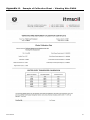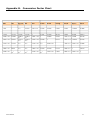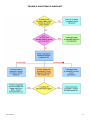
1
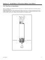
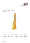
Vibrating Wire Precision Water Level Meter User Manual Man213 1.0.2 07/08/2014 P. Day Chris Rasmussen Chris Rasmussen Manual No. Revision Date Originator Checked Authorised for Issue User Manual 1 Contents Section 1 : 1.01 1.02 1.03 General Information ................................................................................................................. 3 Description ........................................................................................................................................ 3 Operating Principle .......................................................................................................................... 3 Performance...................................................................................................................................... 3 Section 2 : Installation of Precision Water Level Meter .................................................................... 4 2.01 2.02 2.03 2.04 2.04.1 2.04.2 2.04.3 2.04.4 Test Prior to Installation ..................................................................................... 4 Cable Connection and Potting .............................................................................. 5 Installation ....................................................................................................... 5 Cable Jointing ................................................................................................... 6 Preparation of the Cable ..................................................................................... 6 Conductor Connections ....................................................................................... 6 Fitting Mould ..................................................................................................... 6 Filling with Resin ............................................................................................... 6 Section 3 : Termination of Cables .............................................................................................................. 7 Section 4 : Vibrating Wire Precision Water Level Meter Data Reduction Procedures ........... 8 4.01 4.02 The Calibration Certificate ............................................................................................................. 8 Data Reduction................................................................................................................................. 8 Appendix A. Example of Calibration Sheet – Vibrating Wire PWLM ............................................. 10 Appendix B. Conversion Factor Chart ....................................................................................................... 11 Appendix C. Troubleshooting ....................................................................................................................... 12 Figure 5: Preparation of Cable Joint ............................................................................................................ 15 Figure 6: Cable Jointing Kit Wrapping Electrical Connectors & Fitting Mould............................. 16 User Manual 2 Section 1 : General Information 1.01 Description The Precision Water Level Meter (PWLM) consists of a cylindrical weight suspended from a vibrating wire strain gauge, housed within a plastic stilling well. The PWLM is designed to measure water levels in streams, weirs and boreholes where accurate measurements of small water level changes are required. 1.02 Operating Principle The weight connected to the strain gauge has a specific gravity that is slightly greater than that of water. The strain gage works by measuring the load exerted by the weight’s buoyant forces as the water level changes in relation to the fixed position of weight. The change in load changes the wire's tension and resonant frequency. The readout box supplies an electrical pulse to the coil/magnet assembly, which in effect plucks the wire and causes it to vibrate at its resonant frequency. The coil/magnet assembly then acts as a pickup as the oscillations of the wire through the magnetic field induce an alternating current in the coil, which is detected by the readout. The readout converts the sinusoidal alternating voltage to a square wave from which may easily be timed using a frequency oscillator. In this way the period of oscillation may accurately be measured. The relationship between a change in the period of oscillation and the strain of the wire is non-linear, so to facilitate the reading procedure the readout converts the period of oscillation to frequency-squared which has a linear relationship to strain. 1.03 Performance The PWLM has a very good long-term stability but are sensitive to temperature, and an allowance for temperature variations may be necessary when interpolating the results. The PWLM’s can accommodate a thermistor to monitor temperature if such variations are anticipated. User Manual 3 Section 2 : Installation of Precision Water Level Meter 2.01 Test Prior to Installation Before installation the PWLM should be subjected to an operational test with the portable readout connected as follows:Suspend the PWLM and gently attached the weight, loosen the two transit screws that secure the weight hanging hook. The hook should hang freely and not be in contact with the body or the transit screws. Take a zero reading, which should be of a constant value. Transit Screw User Manual Transit Screw 4 2.02 Cable Connection and Potting PWLM’s are usually supplied with 5 metre of cable already connected to the transducer. Additional cable lengths may be added on site using a cable jointing kit, see section 2.04. 2.03 Installation The stilling well should be installed vertically in a position where there is little water turbulence. The vertical position should be such that the weight of the PWLM will be in the desired position relative to the water level. After installation of the stilling well connect the PWLM to the cap of the stilling well and lower the assembly into the stilling well. It is important that the PWLM is centred within the stilling well and that the weight is not touching the side of the stilling well as this will influence the sensor output. After installation the seal screw should be removed from the moisture trap. The trap should be positioned in a dry environment away from the stream or weir. The installation zero reading should now be taken and recorded for later use in data reduction. It is advisable to test the PWLM by raising the cap a few centimetres and recording the change in reading and then calculating the change in engineering units. This will ensure that you are aware of the direction of change of the engineering units, raising the cap simulates a drop in water level. You can reverse the indicated direction of change by reversing the sign of the K or G factor. User Manual 5 2.04 Cable Jointing It is desirable to minimise cable joints, but where they are unavoidable a special joint kit may be supplied. The effectiveness of this joint largely depends on the care with which the jointing operation is carried out. 2.04.1 Preparation of the Cable Thoroughly scrape all wax and dirt from each cable and for approximately 150mm. Prepare the cable ends exactly as shown in Figure 5. Stagger the individual conductor connections. 2.04.2 Conductor Connections Use the crimped connectors to join the conductors and use the electrical insulation tape to wrap the connectors. Stretch the tape to half its original width and apply one layer half lapped over connector area only (Figure 6). Do not warp the tape beyond the pencilled area. 2.04.3 Fitting Mould Trim the ends of the mould with a sharp knife to suit the diameter of the cable. Hold the mould halves in place centred over the splice. Snap both halves together and fit the pouring spouts in the holes. Ensure that both seams are completely snapped together. Tape the ends of the mould body to form a seal. 2.04.4 Filling with Resin Mix the resin thoroughly and maintaining the mould in a level position, spouts uppermost, pour the resin through one spout until both spouts are completely filled. When the resin has solidified and cooled remove the spouts. NOTE: User Manual In cold weather (below 15°C) the resin becomes very viscous. It is therefore advisable to keep the resin in a warm place prior to mixing. Mix the compound until its temperature starts to rise, this decreases the viscosity. 6 Section 3 : Termination of Cables The cables are normally terminated in a 5-channel terminal box or 12 and 24 channel terminal units. The cables enter through waterproof glands. The terminal box has a cover secured by four screws whereas the terminal units have a hinged lid. The cables are terminated as follows:Unscrew the cover or open the lid as appropriate. Unscrew the four fixing screws holding the terminal panel and carefully remove it without straining the connecting leads. Prepare the cables by stripping and cutting back 20cm approximately of the outer insulation and armour. Remove the rubber packing and strip back 5cm of the conductor insulation. Slacken the entry glands and insert the cables. Make connections to the contact block (details of colour coding supplied with each instrument). Retighten the glands to grip the cables. Replace the terminal panel and secure. Connect the readout to each instrument in turn to check connections. User Manual 7 Section 4 : Vibrating Wire Precision Water Level Meter Data Reduction Procedures 4.01 The Calibration Certificate The end of this section shows example of the Calibration Certificate as supplied with each PWLM. 4.02 Data Reduction The mathematical relationship between the frequency of vibration of a tensioned wire and the force applying the tension is an approximate straight line relationship between the square of the measured frequency and the applied force. Engineering units of measurement maybe derived from the frequency-based units measured by vibrating wire readouts, in 2 traditional ways:From ‘Period’ units and from ‘Linear’(F²/1000) units. Calculation using ‘Period’ units The following formula is used for readings in ‘Period’ units. E = K (10^7/P0^2 – 10^7/P1^2) Where; E is the Pressure in resultant Engineering units, K is the Period Gauge Factor for units of calibration (from the calibration sheet), P0 is the Period ‘base’ or ‘zero’ reading P1 is the current Period reading. This method of calculation is used by the Soil Instruments Vibrating Wire loggers’ (models RO-1-VW1 or 2 and with serial numbers starting VL or TVL) internal processors’, for calculating and displaying directly on the loggers’ LCD screen, the required Engineering based units. The loggers’ require ‘Period’ base or zero reading units for entering into their channel tables, to calculate and display correctly the required engineering units. If an Engineering-based unit is required other than the units of calibration, then the correct K factor will have to be calculated using the standard relationship between Engineering units. For example, if the units of calculation required were in KGF/Cm2 and the calibration units were kPa, we can find out that 1kPa is equal to 0.01019 KGF/Cm2, so we would derive the K factor for KGF/Cm2 by multiplying the K factor for kPa by 0.01019 Please see conversion factors in Section 10. Calculation using Linear units The following formula is used for readings in ‘Linear’ units. E = G (R0 – R1) User Manual 8 Where; E is the resultant Engineering unit, G the linear Gauge factor for the units of calibration (from the calibration sheet), R0 is the Linear ‘base’ or ‘zero’ reading R1 is the current Linear reading. Again the Linear gauge factor for units other than the units of calibration would need to be calculated using the same principles as stated in the last paragraph of the ‘Period unit’ section. User Manual 9 Appendix A. Example of Calibration Sheet – Vibrating Wire PWLM User Manual 10 Appendix B. Conversion Factor Chart Pressure, Stress & Modulus of Elasticity MN/m2 or MPa kN/m2 or kp or kPa kgf/cm2 bar atm m H2O ft H2O mm Hg tonf/ft2 psi or lbf/in2 lbf/ft2 1 1000 10.197 10.000 9.869 102.2 335.2 7500.6 9.320 145.04 20886 1 1.019 x 10⁻² 0.0100 9.87 x 10⁻³ 0.1022 0.3352 7.5006 0.0093 0.14504 20.886 0.001 9.807 x 10 -2 98.07 1 0.9807 0.9678 10.017 32.866 735.56 0.9139 14.223 2048.1 0.100 100.0 1.0197 1 0.9869 10.215 33.515 750.06 0.9320 14.504 2088.6 0.1013 101.33 1.0332 1.0132 1 10.351 33.959 760.02 0.9444 14.696 2116.2 9.788 x 10⁻³ 9.7885 9.983 x 10⁻² 9.789 x 10⁻² 9.661 x 10⁻² 1 3.2808 73.424 9.124 x 10⁻² 1.4198 204.45 2.983 x 10⁻³ 2.9835 3.043 x 10⁻² 2.984 x 10⁻² 2.945 x 10⁻² 0.3048 1 22.377 2.781 x 10⁻² 0.43275 62.316 1.333 x 10⁻⁴ 0.1333 1.3595 x 10⁻³ 1.333 x 10⁻³ 1.315 x 10⁻³ 1.362 x 10⁻² 4.469 x 10⁻² 1 1.243 x 10⁻³ 1.934 x 10⁻² 2.7846 0.1073 1.0942 1.0730 1.0589 10.960 35.960 804.78 1 7.031 x 10⁻² 6.895 x 10⁻² 6.805 x 10⁻² 0.7043 2.3108 51.714 6.426 x 10⁻² 1 4.883 x 10⁻⁴ 4.788 x 10⁻⁴ 4.725 x 10⁻⁴ 107.3 6.895 x 10⁻³ 6.895 4.788 x 10⁻⁵ 4.788 x 10⁻² User Manual 4.891 x 10⁻³ 1.605 x 10⁻² 0.3591 15.562 2240.0 144.00 4.464 x 10⁻⁴ 6.944 x 10⁻³ 1 11 Appendix C. Troubleshooting If a failure of any vibrating wire transducer or the electrical cable is suspected, the following steps can be followed. The transducers themselves are sealed and cannot be opened for inspection. The “Troubleshooting Flowchart” should also be followed if any instrument failures are suspected. The steps below and the Troubleshooting Flowchart are applicable generally to any vibrating wire instrument. STEP 1 Before any of the following steps are followed, the portable data logger should be used to verify the stability of the reading and the audio signal from the portable logger should be heard. An unstable (wildly fluctuating) reading from a transducer or an unsteady audio signal are both indications of possible problems with instruments or their related electrical cables. If a portable data logger is giving faulty readings or audio signals from all transducers, a faulty readout unit must be suspected. Another readout unit should be used to check the readings from the transducers and Soil Instruments should be consulted about the faulty readout unit. STEP 2 The resistance across the two conductors of the electrical cable should be checked. This can be done using a multimeter device across the two exposed conductors if the cable has not been connected to a terminal cabinet, or can be done just as easily across the two conductors if the instrument has been connected to such a terminal (or datalogger). The resistance across the two conductors should be approximately of the order of 120 to 180. The majority of this resistance will come from the transducer (say approximately 130). Before proceeding to Steps 3 and 4, the continuity should be checked between conductors and earthing screen of the electrical cable. If continuity exists, a damaged cable is confirmed. STEP 3 If the resistance across the two conductors is much higher than the values quoted in “STEP 1” (or is infinite), a severed cable must be suspected. STEP 4 If the resistance across the two conductors is much lower than the values quoted in “STEP 1” (say 80 or less) it is likely that cable damage has occurred causing a short in the circuit. STEP 5 If the resistance is within the values quoted in “STEP 1” (i.e. 120 to 180), AND no continuity exists between conductor and earth screen and on checking the reading from the transducer, it proves to be still unstable or wildly fluctuating, it must be assumed that the integrity of the circuit is good. A faulty transducer could be suspected if neighbouring construction activities do not account for the anomaly Soil Instruments should be consulted. If the point at which the cable is damaged is found, the cable can then be spliced in accordance with recommended procedures. User Manual 12 TROUBLE SHOOTING FLOWCHART R less than 80 User Manual 13 User Manual 14 5.00 Scrape Sheath 5.00 Cut Sheath Back Cut Sheath Back A 25.00 Scrape Sheath A 25.00 Figure 5: Preparation of Cable Joint User Manual 15 Pouring Spouts Mold Bodies IMPORTANT: Cables and Connector Must be Centerd in Mold. Figure 6: Cable Jointing Kit Wrapping Electrical Connectors & Fitting Mould Bell Lane, Uckfield, East Sussex t: +44 (0) 1825 765044 e: [email protected] TN22 1QL United Kingdom f: +44 (0) 1825 744398 w: www.itmsoil.com Soil Instruments Ltd. Registered in England. Number: 07960087. Registered Office: 5th Floor, 24 Old Bond Street, London, W1S 4AW User Manual 16