1
TRANSI-FLO I SERIES
(Ultrasonic AC Powered Flow Meters)
USER’S MANUAL
HP-316
November 2010
Notice
HOFFER FLOW CONTROLS, INC. MAKES NO WARRANTY OF ANY
KIND WITH REGARD TO THIS MATERIAL, INCLUDING, BUT NOT
LIMITED TO, THE IMPLIED WARRANTIES OF MERCHANTABILITY
AND FITNESS FOR A PARTICULAR PURPOSE.
This manual has been provided as an aid in installing, connecting,
calibrating, operating, and servicing this unit. Every precaution for accuracy
has been taken in the preparation of this manual; however, HOFFER
FLOW CONTROLS, INC. neither assumes responsibility for any
omissions or errors that may appear nor assumes liability for any
damages that may result from the use of the products in accordance with
information contained in the manual.
HOFFER FLOW CONTROLS' policy is to provide a user manual for each
item supplied. Therefore, all applicable user manuals should be
examined before attempting to install or otherwise connect a number of
related subsystems.
During installation, care must be taken to select the correct interconnecting
wiring drawing. The choice of an incorrect connection drawing may result in
damage to the system and/or one of the components.
Please review the complete model number of each item to be connected
and locate the appropriate manual(s) and/or drawing(s). Identify all model
numbers exactly before making any connections. A number of options and
accessories may be added to the main instrument, which are not shown on
the basic user wiring. Consult the appropriate option or accessory user
manual before connecting it to the system. In many cases, a system wiring
drawing is available and may be requested from HOFFER FLOW
CONTROLS.
This document contains proprietary information, which is protected by
copyright. All rights are reserved. No part of this document may be
photocopied, reproduced, or translated to another language without the
prior written consent of HOFFER FLOW CONTROLS, INC.
HOFFER FLOW CONTROLS’ policy is to make running changes, not
model changes, whenever an improvement is possible. This affords our
customers the latest in technology and engineering. The information
contained in this document is subject to change.
RETURN REQUESTS / INQUIRIES
Direct all warranty and repair requests/inquiries to the Hoffer Flow Controls Customer
Service Department, telephone number (252) 331-1997 or 1-800-628-4584. BEFORE
RETURNING ANY PRODUCT(S) TO HOFFER FLOW CONTROLS, PURCHASER MUST
OBTAIN A RETURNED MATERIAL AUTHORIZATION (RMA) NUMBER FROM HOFFER
FLOW CONTROLS’ CUSTOMER SERVICE DEPARTMENT (IN ORDER TO AVOID
PROCESSING DELAYS). The assigned RMA number should then be marked on the
outside of the return package and on any correspondence.
FOR WARRANTY RETURNS, please
have the following information available
BEFORE contacting HOFFER FLOW
CONTROLS:
1. P.O. number under which the product
was PURCHASED,
2. Model and serial number of the
product under warranty, and
3. Repair instructions and/or specific
problems relative to the product.
HFC 9708
FOR NON-WARRANTY REPAIRS OR
CALIBRATIONS, consult HOFFER FLOW
CONTROLS for current repair/calibration
charges. Have the following information
available BEFORE contacting HOFFER
FLOW CONTROLS:
1. P.O. number to cover the COST of the
repair/calibration,
2. Model and serial number of the product,
and
3. Repair instructions and/or specific
problems relative to the product.
LIMITED WARRANTY
HOFFER FLOW CONTROLS, INC. ("HFC") warrants HFC's products ("goods")
described in the specifications incorporated in this manual to be free from defects in
material and workmanship under normal use and service, but only if such goods have
been properly selected for the service intended, properly installed and properly operated
and maintained. This warranty shall extend for a period of one (1) year from the date of
delivery to the original purchaser (or eighteen (18) months if the delivery to the original
purchaser occurred outside the continental United States). This warranty is extended
only to the original purchaser ("Purchaser"). Purchaser's sole and exclusive remedy is
the repair and/or replacement of nonconforming goods as provided in the following
paragraphs.
In the event Purchaser believes the goods are defective, the goods must be returned to
HFC, transportation prepaid by Purchaser, within twelve (12) months after delivery of
goods (or eighteen (18) months for goods delivered outside the continental United
States) for inspection by HFC. If HFC's inspection determines that the workmanship or
materials are defective, the goods will be either repaired or replaced, at HFC's sole
determination, free of additional charge, and the goods will be returned, transportation
paid by HFC, using the lowest cost transportation available.
Prior to returning the goods to HFC, Purchaser must obtain a Returned Material
Authorization (RMA) Number from HFC's Customer Service Department within 30 days
after discovery of a purported breach of warranty, but no later than the warranty period;
otherwise, such claims shall be deemed waived. See the Return Requests/Inquiries
Section of this manual.
If HFC's inspection reveals the goods are free of defects in material and workmanship or
such inspection reveals the goods were improperly used, improperly installed, and/or
improperly selected for service intended, HFC will notify the purchaser in writing and will
deliver the goods back to Purchaser upon (i) receipt of Purchaser's written instructions
and (ii) the cost of transportation. If Purchaser does not respond within thirty (30) days
after notice from HFC, the goods will be disposed of in HFC's discretion.
HFC does not warrant these goods to meet the requirements of any safety code of any
state, municipality, or other jurisdiction, and Purchaser assumes all risk and liability
whatsoever resulting from the use thereof, whether used singly or in combination with
other machines or apparatus.
This warranty shall not apply to any HFC goods or parts thereof, which have been
repaired outside HFC's factory or altered in any way, or have been subject to misuse,
negligence, or accident, or have not been operated in accordance with HFC's printed
instructions or have been operated under conditions more severe than, or otherwise
exceeding, those set forth in the specifications for such goods.
THIS WARRANTY IS EXPRESSLY IN LIEU OF ALL OTHER WARRANTIES,
EXPRESSED OR IMPLIED, INCLUDING ANY IMPLIED WARRANTY OF
MERCHANTABILITY OR FITNESS FOR A PARTICULAR PURPOSE. HFC SHALL NOT
BE LIABLE FOR ANY LOSS OR DAMAGE RESULTING, DIRECTLY OR INDIRECTLY, FROM THE USE
OR LOSS OF USE OF THE GOODS. WITHOUT LIMITING THE GENERALITY OF THE FOREGOING,
THIS EXCLUSION FROM LIABILITY EMBRACES THE PURCHASER'S EXPENSES FOR DOWNTIME OR
FOR MAKING UP DOWNTIME, DAMAGES FOR WHICH THE PURCHASER MAY BE LIABLE TO OTHER
PERSONS, DAMAGES TO PROPERTY, AND INJURY TO OR DEATH OF ANY PERSONS. HFC
NEITHER ASSUMES NOR AUTHORIZES ANY PERSON TO ASSUME FOR IT ANY OTHER LIABILITY IN
CONNECTION WITH THE SALE OR USE OF HFC'S GOODS, AND THERE ARE NO ORAL
AGREEMENTS OR WARRANTIES COLLATERAL TO OR AFFECTING THE AGREEMENT.
PURCHASER'S SOLE AND EXCLUSIVE REMEDY IS THE REPAIR AND/OR REPLACEMENT OF
NONCONFORMING GOODS AS PROVIDED IN THE PRECEDING PARAGRAPHS. HFC SHALL NOT BE
LIABLE FOR ANY OTHER DAMAGES WHATSOEVER INCLUDING INDIRECT, INCIDENTAL, OR
CONSEQUENTIAL DAMAGES.
Disclaimer
Specifications are subject to change without notice.
Some pages are left intentionally blank.
HFC 9708
CONTENTS
1. APPLICATION.............................................................................................................1
2. FUNCTION ..................................................................................................................1
3. DESCRIPTION ............................................................................................................2
3.1. BASIC INFORMATION ..............................................................................................2
3.2. FLOW METER DESIGN .............................................................................................4
3.3. MODEL NUMBER DESIGNATION ...............................................................................8
4. SPECIFICATIONS.......................................................................................................9
4.1. ULTRASONIC SENSORS: NOMINAL ID, RATED AND LIMIT FLOW RATES .......................9
4.2. FLOW METERS: BASIC TECHNICAL SPECIFICATIONS .................................................9
4.3. SENSOR SELECTION ...............................................................................................10
4.4. COMMUNICATION INTERFACE ..................................................................................12
5. METER INSTALLATION AND APPLICATION; BASIC RULES ................................13
6. METER INSTALLATION GUIDE.................................................................................18
6.1. ELECTRONIC CIRCUITS (THE REMOTE ELECTRONIC) .................................................18
6.2. ELECTRICAL CONNECTIONS ....................................................................................19
6.3. ULTRASONIC SENSOR.............................................................................................21
6.4. MECHANICAL ASSEMBLY AND INSTALLATION ...........................................................21
7. METER COMMISSIONING AND CONTROL..............................................................22
7.1. CONFIGURATION ....................................................................................................22
7.2. CONTROL KEYBOARD ............................................................................................26
7.3. AUTOMATED METER TEST .......................................................................................34
HP-316
i
Transi-Flo I Series
HP-316
ii
Transi-Flo I Series
1. APPLICATION
Ultrasonic flow meters HOFFER – Transi-Flow I Series can be used to
measure instantaneous flow rate, mass flow rate as well as the aggregate
quantity or mass of fluid passing through the meter sensor over a given
period of time. The measurement method used allows application of the
HOFFER flow meters for a wide range of fluid types including non-conductive
and specific corrosive fluids. Therefore the flow meters can be used to
measure flow rates of water and other technological fluids, e.g. in chemical
plants. The meters are equipped with the necessary HW and SW facilitating
communication with superordinated control systems.
The flow meter may include either a single-ray (SINGLE BEAM) or a doubleray (DOUBLE BEAM) sensor. The type designations of various meter
configurations and their components are given in a table in section 3.1 below.
2. FUNCTION
The HOFFER flow meter utilizes the impulse-wave transit-time method where
the fluid flow velocity is determined from the flight time of the ultrasonic signal
between two ultrasonic transducers. The flight times are measured for both
directions of the signal wave propagation (upstream and downstream)
whereby any asymmetry in the transducer positions is effectively eliminated.
The flight time of an ultrasonic wave traveling downstream the fluid flow can
be determined as follows:
t1
where
l
c
v
l1
c1
l
l
1
c v.cos c 1
s
is the distance between the head parts of the ultrasonic
transducers [m]
is the ultrasonic signal propagation velocity [m/s] in the
flowing fluid
is the fluid flow velocity [m/s]
is the aggregate thickness of the bottom parts of the
transducers [m]
is the ultrasonic signal propagation velocity [m/s] in
the transducer body material.
The flight time of an ultrasonic wave traveling upstream/downstream the fluid
flow is defined by the following formula; the difference between the
“downstream “ (t1) and “upstream” (t2) flight times is given by the different
signs of the fluid flow velocity term in the fraction denominator.
t2
HP-316
l
l
1
c v cos c 1
s
1
Transi-Flo I Series
For a given transducer, l1 and c1 are known constants.
The ultrasonic signal propagation velocity can be expressed as:
v 1 c v . cos
v 2 c v . cos
for the case of downstream measurement, and
for the case of upstream measurement.
Therefore, the difference between the velocities of ultrasonic signals traveling
downstream and upstream is proportional to the fluid flow velocity v [m/s].
The instantaneous fluid flow rate q is defined by the following formula:
v
v1 v 2
2.cos
q v s k v
where
m / s
3
v
is the fluid velocity [m/s]
s is the effective cross-section of the flow meter sensor [m2], and
k(v) is a correction coefficient the magnitude of which depends on
the fluid velocity.
This coefficient reflects the varying fluid velocity profile in the hydraulic
section of the flow meter.
3. DESCRIPTION
3.1. Basic information
Ultrasonic flow meters HOFFER SE Transi-Flo I Series are electronic devices
designed for measurement of fluid flow parameters in a piping completely
filled with the flowing fluid. The meter consists of a fluid flow sensor (SINGLE
BEAM or DOUBLE BEAM) and an evaluation electronic unit. These two parts
can either be separated or designed as a integral unit. While SINGLE BEAM
includes two ultrasonic transducers (a single-ray sensor), DOUBLE BEAM is
a double-ray sensor including four transducers. Sensor DOUBLE BEAM
provides for better coverage of the fluid velocity profile under a wide range of
operational conditions, in particular with low fluid flow velocities where various
irregularities in the velocity profile may occur. The application of this sensor
extends the range of measured values, allows for shorter fluid-flow
stabilization piping sections at the meter input and output and generally
increases the measurement accuracy.
In the case of a remote electronic of the meter (with separate sensor and the
associated electronic unit), the sensor is connected to the electronic unit by
two (or four) co-axial cables of adequate length. Both “integral” and “remote”
versions of the meter are available in the following configurations:
HP-316
2
Transi-Flo I Series
Regarding function, the evaluation electronic unit of the flow meter can be
divided into the following sections:
- sensor isolation circuits
- sensor output switches
- ultrasonic transducer
- ultrasonic receiver including sensitivity control circuits
- interface circuits to the signal evaluation processor
- signal evaluation processor
- circuits for isolated current, frequency and impulse outputs
- serial communication line circuits
- power supply circuits
The basic configuration of the evaluation electronic unit includes frequency
and impulse outputs. All output signals are isolated from the rest of the meter
circuits.
Optional electronic accessories can further enhance the meter functions.
Among these are: RS 485 communication interface, isolated current output
and resistance thermometer Pt 100. The thermometer measures the
temperature of the flowing fluid and its readings can be used to convert the
fluid rate and volume data into the mass flow data. In the “remote” version,
the basic range of the permitted fluid temperatures can be extended to –4 /
+356°F. The meter can measure the fluid flow parameters in both directions
with indication of the flow direction.
The electronic unit includes a logic output switch whose function and
parameters can be set through the system software according to the
customer’s requirements, selecting one of the following:
- indication of the fluid flow direction
- indication of measured values exceeding the preset level of volume
flow rate
- indication of measured values exceeding the preset level of mass flow
- indication of measured values exceeding the preset aggregate fluid
volume level
- indication of measured values exceeding the preset aggregate fluid
mass level
- indication of measured values exceeding the preset temperature level
- meter failure indication.
The active state of the switching output can be selected either closed or
open.
An adaptive filter included in the signal processing circuits suppresses shortterm fluctuations of the measured flow-rate values due to pulsation of the fluid
in the piping, flow disturbances following action of the flow control devices or
other external interferences. The filter causes the signal output and the
displayed flow values to be delayed by several seconds with respect to the
real-time fluid flow status.
However, should a particular application require a very fast response of the
flow meter, the signal-processing system can be modified to ensure that the
measured data reflect real-time instantaneous parameters of the fluid flow.
Minimum delays in the flow data measurement and processing are usually
necessary in fluid-dosing systems and similar technological applications.
HP-316
3
Transi-Flo I Series
3.2. Flow meter design
3.2.1. The remote electronic
3.2.1.1. Ultrasonic sensor including terminal box
On the outside, the two sensor models (SINGLE BEAM and DOUBLE
BEAM) look the same. The principle difference consists in the number and
arrangement of the incorporated ultrasonic transducers. Sensor SINGLE
BEAM includes two ultrasonic transducers, sensor DOUBLE BEAM four
transducers.
The sensor body is a stainless-steel welded structure consisting of inner pipe
with welded-on ultrasonic transducer holders. The flanges (made of
construction or stainless steel, according to the customer requirements) are
welded to the ends of the inner pipe. The transducers are provided with
hermetic covers made of construction or stainless steel. The electric terminal
board is accommodated in an aluminum box with a thermal insulation insert
between it and the sensor body. The electrical connections are led through
two (in the case of a single-ray sensor) or four (double-ray sensor) PG 9
coaxial leadthroughs. A special valve prevents water condensation inside the
terminal box. The surface finish of the sensor assembly is a powder-paint
coating, hue RAL 7035 for the sensor body, and RAL 7016 for the terminal
box.
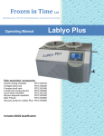
The sensor assembly dimensions are shown in the following table:
Dimensional sketch of the sensor assembly
HP-316
4
Transi-Flo I Series
Nominal Pressure
PSI
Nominal
Dimension
11/4″
11/2″
2″
21/2″
3″
232
P in
5.51
5.91
6.50
7.28
7.87
232
S in
7.13
7.52
8.11
8.66
9.33
232
L in
14.2
14.2
14.2
14.2
14.2
4″
5″
6″
8″
10″
12″
Nominal Pressure
PSI
Nominal
Dimension
232
P in
8.66
9.84
11.3
13.4
16.0
18.2
232
S in
10.1
11.3
12.4
14.3
16.5
18.6
232
L in
14.2
14.2
14.2
17.8
17.8
17.8
Weight of the SINGLE BEAM ultrasonic sensors [lbs]
PIPE DIA IN
232 PSI
11/4″
19.9
11/2″
19.9
2″
24.3
21/2″
26.5
3″
33.1
4″
37.5
5″
39.7
6″
41.9
8″
61.8
10″
99.3
12″
127.9
Weight of the DOUBLE BEAM ultrasonic sensors [lbs]
HP-316
PIPE DIA IN
232 PSI
11/4″
26.5
11/2″
35.3
2″ ÷ 12″
the same as SINGLE BEAM
5
Transi-Flo I Series
3.2.1.2. Evaluation electronic unit
The evaluation electronic unit of the flow meter is located in a plastic box with
a metal sheet base to be mounted on a vertical support plate. At the front
panel of the box there are the flow meter trade name and model/type
designation, product series number, the manufacturer’s trade name and logo,
illuminated two-line display and a control panel including four membrane
push-buttons. A terminal strip is located at the bottom part of the box. To
access the terminals it is necessary to remove a plastic cover under seals.
Fitted at the bottom wall of the box there are an earthing bolt and at least five
plastic leadthroughs (one PG 9 and four PG 7) for cables of circular crosssection. A leadthrough size PG 9 will accommodate (and provide for air-tight
assembly of) a cable of external diameter .236 to .315 in, a PG 7 for a cable
of external diameter .157 to .236 in. Instead of one PG 7 leadthrough, a fourpole connecter for the RS 485 line can be fitted.
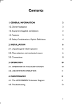
Dimensional sketch of the electronic unit
3.2.2. The integral version
In the integral version, the evaluation electronic unit is mounted directly onto
the meter sensor (SINGLE BEAM or DOUBLE BEAM, see section 3.2.1.1
above) instead of the sensor terminal box. The electronic circuits are fitted
into a cast aluminum box coated with an RAL 1017 paint. As with the
terminal box in the remote electronic, a thermal insulating insert is placed
between the aluminum box and the sensor body. The mechanical connection
is provided by four bolts M5 with hexagon socket heads. With the bolts
loosened the box can be rotated in horizontal plane by 340°. At the rear part
of the box there is a terminal strip under a cover held in position by six bolts
M4 with hexagon socket heads. The bottom wall of the box incorporates five
leadthroughs (one PG 9 and four PG 7) for cables of circular cross-section
and a special valve preventing water condensation inside the box. The
leadthroughs can accommodate and provide for air-tight connection of cables
of diameter 6 to 8 mm (PG 9) or 4 to 6 mm (PG 7). The electronic unit is
delivered with blinded bushings. At the front panel, there is the flow meter
specification information (meter name and model designation, as well as the
manufacturer’s trade name). Before starting-up check if all used bushings
are tight properly and all unused bushings blinded in appropriate way.
HP-316
6
Transi-Flo I Series
Dimensional sketch of a integral version of the flow meter
Nominal Pressure
PSI
Nominal
Dimension
11/4″
11/2″
2″
21/2″
3″
232
P in
5.51
5.91
6.50
7.28
7.87
232
R in
10.6
11.0
11.6
12.1
12.8
232
L in
14.2
14.2
14.2
14.2
14.2
Nominal Pressure
PSI
Nominal
Dimension
4″
5″
6″
8″
10″
12″
232
P in
8.66
9.84
11.3
13.4
16.0
18.2
232
R in
13.5
14.7
15.8
17.7
20.0
21.0
232
L in
14.2
14.2
14.2
17.8
17.8
17.8
3.2.3. Commercial (invoicing) meters
Calibrated meters used for commercial purposes need be provided with officially
certified seals to ensure that no unauthorized modification of the meter functions
or readings may take place. The official certification and meter protection consist
of:
- Stick-on labels with official seals of the responsible organization to be
attached on top of the meter type plate on the evaluation electronic unit box;
- Two (or three, in the case of a integral version of the meter) official seals on
the covers of the electronic unit box to prevent any unauthorized meter
setting action.
Further protective measures shall be adopted after the meter has been installed
by a duly authorized technical organization:
- Two installation seals with official symbols imprinted thereon to prevent
unauthorized opening of the cover of the sensor terminal box (in the case of
a remote electronic of the meter);
- One (or two, in the case of a remote electronic of the meter) installation
seals with official symbols imprinted thereon to prevent unauthorized
opening of the terminal cover on the evaluation electronic unit box.
HP-316
7
Transi-Flo I Series
3.3. Model Number Designation
MODEL TF1-( A )-( B )-( C )-( D )-( E )-( F )-( G )
NOMINAL SIZE
BEAM CONFIGURATION
END CONNECTIONS
INPUT POWER
SERIAL COMMUNICATION
ELECTRONICS CONFIGURATION
SPECIAL FEATURES
NOMINAL SIZE
MODEL TF1-( A )-( )-(
SIZE (A):
)-(
)-(
)-(
)-(
)
1 1/2"
2"
3"
4"
6"
8"
BEAM CONFIGURATION
MODEL TF1-( )-( B )-( )-( )-( )-(
OPTION ( B )
(1)
SINGLE BEAM
(2)
DUAL BEAM
)-(
10"
12"
)
END CONNECTIONS
MODEL TF1-( )-( )-( C )-( )-( )-( )-( )
OPTION ( C )
(F1CS)
150# CLASS ANSI RF CARBON STEEL FLANGES
(F1SS)
150# CLASS ANSI RF STAINLESS STEEL FLANGES
INPUT POWER
MODEL TF1-( )-( )-(
OPTION ( D )
110/220 VAC
)-( D )-(
)-(
)-( )
SERIAL COMMUNICATIONS
MODEL TF1-( )-( )-( )-( )-( E )-( )-(
OPTION ( E )
RS 485
)
ELECTRONIC CONFIGURATION
MODEL TF1-( )-( )-( )-( )-( )-( F )-( )
OPTIONS ( F )
(1)
INTEGRAL RATE AND TOTAL INDICATOR WITH FACE
MOUNTED CONTROLS, IP 67
(2)
REMOTE ELECTRONICS FOR IP 68 WITH 19-FT CABLE
SPECIAL FEATURES
MODEL TF1-( )-( )-( )-( )-( )-( )-( G )
OPTIONS ( G )
(1)
HIGH SPEED RESPONSE VERSION
HP-316
8
Transi-Flo I Series
4. SPECIFICATIONS
4.1. Ultrasonic sensors: nominal ID, rated and limit flow rates
For a given size of the flow meter sensor (SINGLE BEAM or DOUBLE BEAM),
the maximum flow rate and other sensor parameters can be found in the following
table.
Meter Sizes and Flow Rates
SINGLE
BEAM
+/-1%
+/-5%
DUAL
BEAM
+/-0.5%
+/-3%
Line Size:
1¼” 1½” 2” 2½” 3”
4”
5”
6”
8”
10”
12”
Max. Flow
Rate GPM:
88
140 220 352 660 1056 1541 2201 3962 6164 8805
Min. Flow
Rate GPM:
6.6
10
Min. Extended
Flow Rate:
0.88
1.4 2.2 3.5 6.6 10.5 15.4
15
26
39
61
96
140
250
391
559
22
40
62
88
4.2. Flow meters: basic technical specifications
Rated pressure of the measured fluid (PSI)
232
Temperature of the measured fluid
32° to +302°F (remote electronic)
32° to +194°F (integral version)
Ambient temperature
+41° to +131°F
Maximum ambient relative humidity
80 %
Storage temperature
-14° to +158°F at the relative humidity up
to 70 %
Protection class
- evaluation electronic unit, integral
version
- evaluation electronic unit, remote
electronic
- ultrasonic sensors SINGLE BEAM,
DOUBLE BEAM
Sensor installed in piping
IP 67
IP 65
IP 67
Flanges 11, ČSN EN 1092-1
Connecting cables for sensors
Standard length 196.9 in, maximum length
39.4 in
Max. difference in cable lengths
3.94 in.
Electronic unit, remote electronic
- dimensions
- weight
- power supply
- stand-by power supply
- power requirement
- mains fuse
- protection against electric shock, ČSN
332000-4-41
Length 9.06”, height 8.54”, width 3.35”
3.31 lbs
100 250 V, 50/60 Hz
3 V, Li battery (Lifetime 5 years)
6 VA
T 250 mA, 250 V
Automated disconnection from power
supply in the TN-S network
HP-316
9
Transi-Flo I Series
Evaluation electronic unit, integral version
- dimensions
- weight
- power supply
- stand-by power supply
- power requirement
- mains fuse
- protection against electric shock,
ČSN 332000-4-41
Length 5.98”, height 5.31”, width 8.07”
5 lbs
100 250 V , 50/60 Hz
3 V, Li battery (Lifetime 5 years)
6 VA
T 250 mA, 250 V
Automated disconnection from power
supply in the TN-S network
minimum 0.1 m/s
maximum 10 m/s
2 x 16-digit alphanumerical LC display
Fluid flow velocity
Display
- impulse, 0.1 to 1,000 l/imp (impulse
length 50 ms)
- frequency, 0 to 1,000 Hz or 10 kHz
(corresponds to flow rate 0 to qs)
Outputs (optoelectronically isolated)
- switching output 24 V AC/0,1 A
Optional equipment
-communication line RS 485
-isolated current output 0 ÷ 20 mA or
4 ÷ 20 mA (corresponding to the flow rate
range of 0 to qs)
-mass flow rate measurement accessory
-modification for extended range of fluid
temperature measurements; from -4°F
to +356°F (remote electronic)
-pipe-end flanges, flange packing pieces,
bolts and nuts
-sensor's protection IP 68
-two direction flow measurement and
direction indication
4.3. Sensor selection
The meter sensor shall be selected with respect to the fluid flow
parameters at the measuring location. The normal steady-state flow rate
should be as close as possible to the rated flow rate of the sensor (see
the table in section 4.1 above). Attention shall be also paid to the
pressure loss value of the sensor which, although it is generally very low,
adds up to the total losses of the fluid piping, in particular at high flow
velocities.
HP-316
10
Transi-Flo I Series
Pressure losses of ultrasonic sensors
HP-316
11
Transi-Flo I Series
4.4. Communication interface
All HOFFER ultrasonic flow meters can be provided with isolated serial
communication line RS 485. The communication line parameters are:
baud rate 4,800 Bd, 8-bit data format, one non-data bit, and optional
parity in both signal transmission directions. The communication
protocol includes, among others, the measured and processed fluid
flow data such as instantaneous volume or mass flow rates, the total
volume or mass of the fluid flow, and the lengths of the periods of the
meter operation, meter failure and power supply failure.
HP-316
12
Transi-Flo I Series
5. METER INSTALLATION AND APPLICATION; BASIC RULES
When using an ultrasonic flow meter in a piping containing a particular
fluid, certain conditions need be met to ensure correct measurements.
The limiting operational parameters of the fluid (i.e. temperature,
pressure and flow velocity) as well as the mechanical design and
properties of the meter sensor (flow stabilisation piping sections before
and after sensor, complete flooding of the sensor cavity at all times,
elimination of cavitation effects and fluid foaming) must comply with the
requirement for steady fluid flow with no gas bubbles or foam
appearing in the piping. Such conditions are different for various types
of fluid and need be correctly identified for each specific measuring
spot and/or technological piping system.
CAUTION: Ultrasonic flow meter of a specific DN must not be
used in piping of lesser sizes (smaller DN).
The ultrasonic flow meter shall be applied/installed in observance of
certain rules concerning meter placement in the fluid piping so as to
ensure that the measurement accuracy complies with the meter
specifications. Thus sensor SINGLE BEAM requires flow-stabilization
straight sections of piping of the length of 5D (D = sensor ID) at the
input and 3D at the output where such arrangement effectively
eliminates any flow disturbances due to 90° pipe bends, changes in the
piping diameter or similar simple flow-interference factors. With sensor
DOUBLE BEAM, the same flow stabilization arrangement ensures a
wider range of measured values at the specified measurement
accuracy (see section 4.1).
Required straight piping sections to stabilize the fluid flow through the sensor
If there is a pump located in the piping on the input side of the flow sensor, the
required length of the stabilization piping is 20 D. If there is a valve or similar
flow control element at the sensor input, the required stabilization length is 40
D. If such control element is fully open, the stabilization length is 10 D.
HP-316
13
Transi-Flo I Series
Straight piping sections to stabilize the fluid flow after a “disturbance” in the piping:
If any fluid-flow control element is located in the piping on the sensor output
side, the sufficient length of the flow stabilization piping is 3 D.
Required straight piping section for a “disturbance” located at the sensor output
HP-316
14
Transi-Flo I Series
In the cases where, in the periods of low flow rate, the fluid level in various parts
of the piping may sink, the flow meter sensor shall be located at a bottom
pocket of the piping to ensure full flooding of the sensor at all times.
Flow sensor location at the “bottom pocket” of the fluid piping
If a flow sensor is to be installed in a vertical section of the fluid piping, the fluid
flow direction shall always be upwards.
Sensor installed in a vertical section of the fluid piping
HP-316
15
Transi-Flo I Series
To ensure correct flow rate measurement, the internal section of the meter
sensor shall always be filled with the flowing fluid. Therefore the basic rule to
follow regarding the meter sensor placement is to avoid top pockets in the fluid
piping and, in the cases where the sensor is located in a vertical section of the
piping and/or near the place where the fluid leaves the piping system, the flow
direction in the sensor should not be downwards.
Examples of incorrect sensor placement
The following pictures show correct and incorrect ways of the sensor installation
in a horizontal piping section with respect to the possible positioning of the
meter display unit.
HP-316
16
Transi-Flo I Series
The measured fluid shall be free of larger solid particles and air bubbles either
coming into the fluid through leaks in the piping or originating by the cavitation
process in the sensor or other piping components. If cavitation is suspected to
appear in the sensor or piping, the fluid pressure in the sensor or the respective
piping section needs be increased.
The above sensor installation rules apply to both integral version of the flow
meter and the separately installed sensor units provided with the terminal boxes
(the “remote” version of the meter).
In the piping systems used to deliver liquids such as rape-seed oil, black oil,
caprolactan or chemical compounds with easily separable components, it is
recommended to mount flow meters in a vertical position with the measured
fluid flowing upwards. This arrangement ensures better mixing action and
homogenity of the fluid flowing through the meter sensor.
The pressure loss vs. flow rate characteristics of individual sensor models are
shown in a table in section 4.3 above. In the cases of commercial (invoicing)
meters, the evaluation electronic unit of the meter shall be supplied from the
mains (230 V, 50 Hz) by a separate power line with an overcurrent circuit
breaker to be sealed at the ON position, where the switching-off actions shall
be reserved to duly authorized staff only. The recommended power supply
cable is CYKY 3x.002 in2 with the external diameter .412 in, and the associated
overcurrent circuit breaker should be rated at 6 A. The recommended cable for
the RS 485 communication line is JYTY – Al with laminated foil 2D x .0015 in2
with a repeater for every 1,000 m of the line.
HP-316
17
Transi-Flo I Series
6. METER INSTALLATION GUIDE
The meter assembly and installation directions given in this manual shall be
strictly observed.
To prevent undesirable interference between the power and signal devices,
the power cables shall be placed at least 4.84 in. away from all signal cables
(the coaxial cables connecting the sensor with the signal processing
electronic circuits in the case of a remote electronic of the meter, the RS 485
communication line and the output signal cables). If a signal cable needs be
extended, the cable conductors shall be soldered and the soldered joint
protected against environmental and mechanical stresses by a suitable
installation box. All cables shall be led outside the thermal insulation layers on
the fluid piping. To connect a Pt 100 thermometer, the current output and the
RS 485 communication line, use shielded wires with the shield connected to
the ground potential terminal on terminal board X1 in the electronic unit box
(or X2, see section 6.2 below). Shielded wires are also recommended to be
used for the frequency and impulse output signals where the shields should
be connected to the ground potential in the superordinated electronic control
system.
Sensor must be grounded properly. For grounding use a conductor with
minimum cross section area .006 in2 and connect the conductor to grounding
bolts of evaluation electronic and flow sensor (see figure here below).
Earthing connection between the sensor and the electronic unit (the remote electronic)
6.1. Electronic circuits (the remote electronic)
The electronic signal processing unit shall be mounted in a vertical position
on an installation frame. The interconnection between the electronic unit and
the meter sensors (SINGLE BEAM or DOUBLE BEAM) is described in
section 6.2 below. The connecting coaxial cables should not differ in length
by more than 0.1 m.
HP-316
18
Transi-Flo I Series
6.2. Electrical connections
A remote electronic of flow meter with flow sensor SINGLE BEAM
A remote electronic of flow meter with flow sensor DOUBLE BEAM
HP-316
19
Transi-Flo I Series
An integral version of flow meter
Connector X4 serves the purposes of the equipment calibration, servicing
and parameter setting at the manufacturer’s plant. The signal outputs
(frequency, impulse and current outputs) are isolated and power from a
separate isolated power source. The frequency and impulse outputs can be
used in either passive or active operational modes, while the current output is
always active. In view of the arrangement used (a common power source
and therefore the possibility of equalizing currents flowing between the
outputs), it is recommended not to use more than two outputs in the active
mode at any time. If the frequency and/or impulse outputs are used in the
passive mode (pins W1 through to W6 are disconnected), the optocoupler
current shall not exceed 20 mA. Pushbutton S1, if depressed, resets the data
on the aggregate fluid volume that has passed through the flow meter.
Terminals 1 and 2 at terminal board X1 (in the case of a remote electronic) or
X2 (in the case of a integral version of the meter) can be connected to a relay
coil in series with an external AC power source and so provide for indication
of the flow direction or other selected parameter status. Thermometer Pt 100,
if used, shall be connected to terminals 1 to 5 at terminal board X2 (in the
case of a remote electronic) or X3 (in the case of a integral version of the
meter). The thermometer signal is used to convert the fluid volume data to
mass data in special flow meter configurations. If isolated voltage, frequency
or impulse outputs are required, the W-pins shall be connected as shown in
the table below:
Type of el. unit
Frequency output
Impulse output
HP-316
INTEGRAL
W3 to W1
W2 to W1
20
REMOTE
W4 to W6
W5 to W6
Transi-Flo I Series
As shown in the schematic diagrams in section 6.2 above, isolated current
outputs 0 to 20 or 4 to 20 mA and an output for the RS 485 communication
line are available at specific terminals and can be used according to the
requirements of the customer. In the remote electronic of the meter, the
ultrasonic sensor is connected to the signal processing unit by two or four
coaxial cables (see the schematic diagrams).
If the flow meter is to serve the purposes of a standard/invoicing meter,
switch S3 and one section of switch S2 should be sealed and provided with
calibration mark. The remaining section of switch S2 (S2:1) may be used to
select display of the instantaneous velocity or flow rate of the measured fluid.
The following table shows the control functions of double switches S2 and
S3.
Operational modes and combinations of the positions of switches S2 and S3
Measuring mode
S2:1 position OFF
S2:2 position OFF
S3:2 position OFF
6.3. Ultrasonic sensor
Ultrasonic sensors shall not be covered with thermal insulation. The
connecting coaxial cables shall not be attached to piping containing warm
fluid. The sensors shall be installed in the piping in such a way as to ensure
that the associated electronic unit (in the case of an integral version) or the
terminal box (in the remote electronic of the meter) is facing up or down.
The position of the sensor in the piping shall be such that the hydraulic part of
the sensor is fully flooded by the measured fluid at all times. If the sensor is
installed in a vertical section of the piping, the measured fluid shall only flow
in the upward direction. Disregarding these or other sensor installation rules
(see section 5) may result in incorrect flow rate or flow volume readings.
6.4. Mechanical assembly and installation
Ultrasonic sensors shall be fitted into the piping by means of end flanges
(size 11, ČSN EN 1092-1) with suitable counterparts at the piping ends. The
internal diameters of the pipe flanges and the piping itself shall be the same
as that of the sensor. The pipe flange faces shall be perpendicular to the
piping axis. The piping sections including sealing rings at the sensor input
and output shall be co-axial with no protruding edges in the flow channel.
The separate box with electronic circuits (in the case of a remote electronic of
the meter) shall be attached to a suitable vertical support plate by means of
four bolts of diameter .197 in.
HP-316
21
Transi-Flo I Series
7. METER COMMISSIONING AND CONTROL
7.1. Configuration
After the meter has been installed in the piping (which implies, in the case of
a integral version, installation of the complete meter or, in the case of a
remote electronic, installation of the flow sensor in the piping and connecting
it to a separate signal processing unit), the meter can be energized. Very
soon (within a few seconds) the meter will adopt the measuring (and data
display) mode and the frequency, impulse and isolated current outputs will be
operative. The impulse and frequency outputs can be used either in the
passive mode (where the function is essentially that of a transistor switch with
power supplied from the associated equipment) or in the active mode where
the output circuits are powered from an internal isolated source. The
selection of the output mode of operation is done by connecting or
disconnecting the respective W pins (see section 6.2 above).
The aggregate flow volume or mass data transmitted by the RS 485
communication line can be reset either via the communication line or
manually, using the RESET push-button located under the terminal board
cover.
7.1.1. Display Data
The data on the display include selected measured quantities and information
on the flow meter operational status.
7.1.1.1. Meter status information
The first three seconds after connecting the meter to the power source the
display reads
Flowmeter
HOFFER
In the normal operation, the symbol appearing at the last digit position on the
second line informs about the current mode of operation of the signal
processing electronic unit. The characters used and their meanings are as
follows:
I
+
C
W
T
electronic unit initialization
measurements in the positive flow direction
measurements in the negative flow direction
calculation of measured values, output signal generation and display
stand-by mode
data communication (data being sent).
Under normal operating conditions the above characters regularly replace
one another. In the case of an error due to a sensor failure, loss of a sensor
signal due to a cable failure, presence of an air bubble or a mechanical
particle in the fluid flow, an “R” will appear at the last position on the first line
HP-316
22
Transi-Flo I Series
and the “I” and “+” signs will appear in turns at the last position on the second
line of the display unit. A failure of the electronic unit will usually be
manifested by discontinued regular changes of the system status symbols on
the display.
7.1.1.2. Display of measured data
Up to three measured quantities can be displayed simultaneously; one on the
first line, and the other two in turns on the second line of the display unit. The
switching frequency can be selected in terms of the number of measuring
cycles per display time of one measured quantity.
Most often the first display line is used to show the volume flow rate (in
m3/hod) or the mass flow rate (in metric tons per hour), and the second
display line to display the total volume (in m3) or the total mass (in metric
tons) alternatively with the fluid temperature in °F. However, the customer is
free to define other combinations of the data to be displayed and/or to select
other optional data units from the software menu available.
7.1.2. Review of the measured quantities
Volume flow rate
Relative volume flow rate
Mass flow rate T
Relative mass flow rate T
Volume (aggregate value)
Volume + (volume of the fluid passed in the positive direction) O
Volume - (volume of the fluid passed in the negative direction) O
Mass (aggregate mass) T
Mass + (mass of the fluid passed in the positive direction) T, O
Mass - (mass of the fluid passed in the negative direction) T, O
Temperature T
Density T
Sound propagation velocity
Fluid flow velocity through the sensor flange
Start of the measurement period (date and time of the last resetting command)
Duration of the measurement period
Duration of a meter error condition
Duration of a power failure period
Date
Time
Comment:
Quantities denoted T will only be measured and displayed if the meter
configuration includes a thermometer; quantities denoted O require that the
flow meter has been set for measurements in both fluid-flow directions.
HP-316
23
Transi-Flo I Series
7.1.3. Review of the measured quantity units
Volume flow rate
Mass flow rate
3
Volume
3
t/hour
t/min
m /hour
3
m /min
1,000 m
3
m
m /s
3
t/s
l/hour
kg/hour
l/min
kg/min
l/s
kg/s
bbl/hour
tons/hour
bbl/min
tons/min
bbl/s
tons/s
3
lb/hour
ft /hour
3
l
kg
1,000 bbl
1,000 tons
bbl
ton
3
1,000 ft
ft /min
lb/min
3
lb/s
ft /s
Mass
1,000 t
t
lb
3
ft
1,000 gal
gal
gal/hour
gal/min
gal/s
Temperature
Density
°C
°F
t/m
3
kg/m
Velocity
3
m/s
ft/s
3
g/cm
3
tons/m
3
lb/ft
Names of selected units
bbl
ft
American barrel
Foot
s
min
gal
American gallon
hour
ton
American ton
°C
Pound
°F
lb
3
m
l
HP-316
Cubic meter
Liter
24
Second
Minute
Hour
Degree Celsius
Degree Fahrenheit
t
Metric ton
kg
Kilogram
Transi-Flo I Series
7.1.4. Unit conversion table
Volume flow rate
3
1 m /hour =
3
0.01666667 m /min
3
0.0002777778 m /s
1,000 l/hour
16.66667 l/min
0.2777778 l/s
6.289387 bbl/hour
0.1048231 bbl/min
0.001747052 bbl/s
3
35.31467 ft /hour
3
0.5885778 ft /min
3
0.009809630 ft /s
264.1708 gal/hour
4.402846 gal/min
0.07338077 gal/s
Mass flow rate
1 t/hour =
1.102311 tons/hour
0.01837185 tons/min
0.0003061975 tons/s
2,204.623 lb/hour
36.74371 lb/min
0.6123952 lb/s
Volume
3
1m =
6.289387 bbl
3
35.31467 ft
264.1708 gal
Mass
1t=
1.102311 tons
2,204.623 lb
Density
1 t/m =
3
3
1.102311 tons/m
3
62.42797 lb/ft
Temperature
tF =
32 + 1.8 tC
Velocity
1 m/s =
3.280840 ft/s
HP-316
25
Transi-Flo I Series
7.2. Control Keyboard
T1
T2
T3
T4
The push-button control of the meter is shown in a schematic diagram in Fig.
7.2.1 (page 33). The system can be operated in two different modes where
the switching-over action between the operation modes and individual
functional blocks within a selected mode can be initiated by depressing the
push-button the image of which is depicted at the given transition position.
From the diagram it follows that a transition from one block to the next one
(on the right-hand side) will be done by depressing the T2 button, while a
transition to the previous block (next on the left-hand side) by depressing the
T3 button.
The Zero Reset block can only be activated in the cases of technological
meters (the software switch in the “NF” position). In the case of commercial
(invoicing) meters, where the switch is in the “F” position, the Zero reset block
is missing.
Upon energizing, the meter will automatically adopt the display mode with the
pre-selected (initial) quantity displayed (see description below). The display
mode will also become operative if no push-button has been depressed over
the period of 300 measurement cycles (5 minutes for a measurement cycle of
1 s).
Any push-button control actions will not disturb the measuring functions of the
meter in any way. A detailed description of individual “block” functions
controlled by the push-button unit is given in the following paragraphs.
7.2.1. Data display mode
The flow meter in full configuration can measure and evaluate any of the 20
physical quantities listed in section 7.1.2 on page 21. In the data display
mode, any of the measured quantities can be displayed. The display format is
as follows:
Line 1 – name of the measured quantity in the selected language
(Czech, English, German, Spanish, Italian or French);
Line 2 – the measured value in the selected unit system.
Upon switching the power on, the system activates the data display mode
whereby the measured value of the pre-selected (“initial”) physical quantity is
displayed. Each of the 20 physical quantities available can be selected as the
initial one.
HP-316
26
Transi-Flo I Series
If the operator depresses push-button T1, another measured quantity will be
displayed (the next on the list in section 7.2.2). Then, unless T1 is depressed
again within 5 minutes, the initial quantity will be displayed again.
To leave the Data Display Mode for the Parameter Setting Mode, depress
push-button T4 (see Fig. 7.2.2, page 33). Select the desired operating mode
(function block) by push-button T1 and confirm the selection by depressing
T4 again.
7.2.1.1. Volume flow rate
The value of the measured volume flow rate is displayed as a 3- or 4-digit
number (this is determined by the manufacturer with respect to the meter
application). Provided the flow meter has been set for measurements in both
directions of flow, the sign before the reading indicates the flow direction (“+”
for the flow direction shown by the arrow sign on the meter body, “-“ for the
opposite direction).
7.2.1.2. Relative volume flow rate
The displayed reading shows the ratio (in per cent) of the measured volume
flow rate to the specified maximum volume flow rate.
7.2.1.3. Mass flow rate
The mass flow rate can be measured and the measured data displayed only
on condition that the meter configuration includes a thermometer and that the
fluid density vs. temperature characteristic is known. For more technical
details of the readings see the comments to section 7.2.1.1 above. If a
thermometer is not installed, the mass flow rate function block is skipped
when selected by push-button T1.
7.2.1.4. Relative mass flow rate
See the comments to section 7.2.1.2 above concerning the relative volume
flow rate.
7.2.1.5. Volume
The aggregate fluid volume passed through the flow sensor during the
measurement period, i.e. from the moment the volume data were reset by the
reset push-button on the meter, or since the measurement start command
from the superordinated control system was received via the RS 485
communication line, or since the data-resetting command was actuated using
the T push-buttons as described in section 7.2.2.8 on page 29. The displayed
value can have up to 7 digits; higher readings are shown in the form of
products of real numbers and appropriate powers of 10 (the “E” format). The
reading sensitivity is 0.01 l, the maximum reading is 2.8.109 m3. In the case of
bi-directional measurement, the aggregate volume reading is the difference
between the volume passed in the positive and the negative direction of the
fluid flow. The displayed value includes the polarity sign.
HP-316
27
Transi-Flo I Series
7.2.1.6. Volume +
Applicable only in the case of bi-directional measurement. The reading
represents the aggregate fluid volume passed in the positive flow direction
(see the arrow on the meter body). The reading format and the range of the
measured values are as described in section 7.2.1.5 above.
7.2.1.7. Volume See section 7.2.1.6, for the reverse flow direction.
7.2.1.8. Mass
See section 7.2.1.5, for the aggregate mass of the fluid passed through the
flow sensor. The reading sensitivity is 0.01 kg.
7.2.1.9. Mass +
See section 7.2.1.6, for the aggregate mass flow in the positive direction.
7.2.2. Parameter setting mode
When selecting the parameter setting mode (see section 7.2.1), the operator
will be requested to enter a four-digit password.
7.2.2.1. Password
The first display line will read
PASSWORD
and the first digit position on the second line will display 0. Depress pushbutton T3 repeatedly to increase the number by 1 at a time (after 9 will follow
0 again). Select the correct number at the first digit position and then depress
push-button T2 to move to the second digit position and repeat the number
setting procedure with push-button T3. Progress to the third and fourth digit
positions and enter the correct password – a combination of four numbers
(see the schematic diagram in Fig. 7.2.3, page 34).
Confirm the entry of the correct password by depressing push-button T4.
Provided the password entered is correct, the system will proceed to the
language selection block. In the case of an incorrect password the system
will request a new password entry. After three consecutive entries of incorrect
passwords the system will switch over to the data display mode and will not
permit further entry into the parameter setting mode. A new attempt at the
password entry is only possible after system de-energizing and repeated
switching on of the power supply.
Should the operator forget the password, it is possible to use the
manufacturer’s password supplied with the system (0200). This shall be done
as follows: switch off the power, depress and hold push-button T4 and switch
the power on again.
HP-316
28
Transi-Flo I Series
The user password can be changed at any time in the parameter setting
mode using the procedure described in section 7.2.2.5 on page 26.
7.2.2.2. Meter setting procedures
The meter parameters that can be defined or re-defined in the parameter
setting mode include: the language of the messages appearing on the
display, units of the displayed quantities, the user password required for entry
into the parameter setting mode, the initial measured quantity, specified
values of some measured quantities (qs, impulse number – liters per imp.,
threshold/sensitivity level, and the maximum/limit values of fluid flow rate,
volume and temperature), as well as the date, day of the week, time of the
day, start of the measurement period and meter zero position (only with the
technological meters).
The procedures to be used in setting particular parameters are described
below. Upon initialization of a particular parameter setting mode, the name of
the function block concerned will appear on the first line of the display in block
letters, e.g.
LANGUAGE
At the same time, the current parameter name or value will appear on the
second line. If you wish to pass on to the next parameter, depress T2; by
depressing push-button T3 you will return to the previous parameter. Any
parameter changes are done using push-button T1, confirmation of the new
value by push-button T4. The display will then read
PARAMETER SET
To leave the current parameter setting mode and proceed to another
parameter block, depress push-button T2. If you wish to return to the
previous block, depress T3. To leave the parameter setting mode completely
(and enter the data display mode for the parameter just set), depress pushbutton T4.
7.2.2.3. Language selection
The operator can choose from any of the six languages available (see Fig.
7.2.4, page 34). The language setting mode will be initiated as soon as the
system acknowledges the correct user password. The first line on the display
will then read
LANGUAGE
or a message to the same effect in the actually defined language. On
delivery, the language selected will be Czech unless the customer has
specified their required language in the product order. The second display
HP-316
29
Transi-Flo I Series
line will identify one of the languages available (e.g. Czech). Depress
repeatedly push-button T1 to select the desired language. Upon selecting the
language, confirm the setting by depressing push-button T4. The message
on the display will inform the operator of completion of the parameter setting
in the newly selected language.
7.2.2.4. Measuring unit selection
In this parameter setting mode, the desired measuring unit can be associated
with each measured physical quantity (see Fig. 7.2.5, page 35). Upon
initiating this mode, the first line of the display will read
UNITS
while the name a physical quantity will appear on the second line. Depress
repeatedly push-button T1 to select the desired quantity and confirm by
depressing T4. The quantity name will then appear on the first line and the
second line will display one of the measuring units available. Select the
desired unit by T1 and confirm by T4. Depress push-button T3 to access
another measured quantity or use T2 to proceed to another parameter to be
set.
7.2.2.5. New password definition
NEW PASSWORD
In this mode, the operator/user may modify the existing password used to
access the parameter setting mode (see Fig. 7.2.6, page 35). Depress pushbutton T4. The first digit position on the second line will display 0. Set the new
password (a combination of four numbers) using the procedure described in
section 7.2.2.1 on page 26. Upon final confirmation by depressing pushbutton T4, the legend Parameter Set will appear on the display. From then
on, only the new password will be effective.
7.2.2.6. Initial quantity selection
Upon accessing this parameter setting mode, the first line of the display will
read
INITIAL QUANTITY
and the second line will give the quantity’s name (see Fig. 7.2.7, page 36).
Select the desired initial quantity using push-button T1 and confirm the
selection by T4.
HP-316
30
Transi-Flo I Series
7.2.2.7. Definition of limit values
LIMIT VALUE
Here the operator can set altogether 11 (limit) values of parameters. The
detailed description of the procedures concerned is shown in Fig. 7.2.8 on
page 37. Select the desired parameter by push-button T1 and confirm the
selection by T4. The name of the parameter and the associated measuring
unit will then appear on the first line of the display and the second line will
show the previously defined limit value (with the exception of the date and
time). The limit value unit shall always be the same as that selected for data
display. For example, if the volume flow rate is displayed in liters per second,
the limit value of volume flow rate shall also be defined in l/s. If the mass flow
rate measurement mode is selected and the data are displayed in metric
tons, the impulse number shall also be defined in t.
Upon depressing push-button T2, the previously set limit value will disappear
from the second line and 0 will be displayed in the first digit position. Use
push-buttons T3 and T2 to set the digital value and T1 to insert the division
signs (a comma in the position of a decimal point, dot in the date and colon in
the case of time).
The day in the week information is to be set as follows:
0 – Sunday
1 – Monday
2 – Tuesday
3 – Wednesday
4 – Thursday
5 – Friday
6 – Saturday
A figure entered may have up to seven digits. The date and time data shall
include initial zeroes; e.g. the date of 3 July, 2001 shall be recorded as
03.07.01 and the time 7 minutes past 9 a.m. as 09:07:00. Confirm the
selection by depressing push-button T4.
In the case of a commercial (invoicing) meter, neither qs, impulse number or
sensitivity (low flow cutoff) can be reset by the user as these settings are
reserved to the duly authorized testing authority. Therefore, for commercial
meters, these parameters will not appear on the list of limit values to be reset.
HP-316
31
Transi-Flo I Series
List of parameters (limit values, date and time)
Qmax
units
ICIS
- Maximum (overload) flow rate qs in the given measuring
- Impulse number, defining fluid volume or mass (in
selected units) per one impulse at the impulse output.
Date
- The actual calendar date.
Day of the week - The actual day of the week.
Time of the day - The actual time of the day.
Low flow cutoff - The flow rate level, in per cent of qs, below which the
meter will display and at its outputs indicate zero flow
rate.
Vol flow limit
- Maximum volume flow rate level; where a binary output
is associated with this parameter, it will indicate values
exceeding this limit.
Mass flow limit
- Maximum mass flow rate; where a binary output is
associated with this parameter, it will indicate values
exceeding this limit.
Volume limit
- Maximum aggregate volume; where a binary output is
associated with this parameter, it will indicate values
exceeding this limit.
Mass limit
- Maximum aggregate mass; where a binary output is
associated with this parameter, it will indicate values
exceeding this limit.
Temp limit
- Maximum temperature; where a binary output is
associated with this parameter, it will indicate values
exceeding this limit value.
Comment: The limit values for all the above parameters shall be given in
units selected using the procedure described in section 7.2.2.4 on page 27.
Should new parameter units be selected, the limit values need be re-defined
accordingly; otherwise the meter function would be incorrect.
7.2.2.8. Resetting aggregate quantities
Upon entering this mode, the corresponding message will appear on the
display (see Fig. 7.2.9, page 37). If resetting of aggregate quantities is not
required, depress push-button T2 to access the next parameter-setting block.
Confirm your intention to reset the aggregate quantities by depressing T4.
The display will then ask
RESET?
At this stage, you can still return to the initial step of the resetting mode by
depressing T3. Depress T4 to reset the aggregate readings of the flow
volume and flow mass, the operational information (the meter operation time,
the error time and power loss time) and define the start of a new
measurement period (the date, hour and minute of the same). The system
will respond with a confirming message (Parameter Set).
HP-316
32
Transi-Flo I Series
7.2.2.9. Meter zero setting
Before leaving the manufacturing plant, every flow meter is carefully set for
correct operation. One of the key parameters in this respect is the meter zero.
A correctly set meter zero implies that at zero flow rate (or zero fluid flow
velocity through the meter sensor) the meter indicates a zero flow rate (zero
fluid flow velocity). The setting value (a meter zero shift) is expressed in
inches per second. The meter zero shift as identified in the manufacturing
plant is stored in the meter memory under the name of initial (in-production)
zero setting value.
Meter component ageing and other factors acting over long-term operational
periods may result in minor meter zero displacements. To eliminate these,
use the automated zero resetting function. However, great care should be
taken in employing this function. First of all, the zero flow rate condition shall
be ensured (make sure that the closing valve in the piping is not leaking).
Only then the zero resetting function may be used.
A detailed description of the zero resetting block is shown in Fig. 7.2.10 on
page 38. Upon initiating this function, the operator shall select either the inproduction or automated meter zero setting mode. The selection is done by
push-button T1, confirmation by T4. When the in-production setting mode is
selected, the meter zero is reset using the zero shift value determined in the
manufacturing plant.
In the automated zero setting mode, the meter will first ask whether the fluid
flow rate through the meter sensor is really zero (the main requirement for a
successful zero setting). If it is not so, cancel the setting process using pushbutton T3. Upon confirmation by push-button T4 the display will show the
message “WAIT FOR 100”. The zero setting procedure lasts 100 measuring
cycles. The actual number of measuring cycles performed is shown on the
second display line.
After 100 measuring cycles the zero displacement is evaluated. If it is smaller
than 50 in/s, the shift value is stored and the display with read “PARAMETER
SET”. If the value is greater than 50 in/s, a notice to this effect is displayed.
However, this is highly unlikely; in such as case it is recommended to check
again whether the fluid flow has indeed been completely stopped. Use pushbutton T3 to invalidate the setting and push-button T4 to run the setting
procedure anew. The meter zero setting function is available only with
technological flow meters.
HP-316
33
Transi-Flo I Series
7.2.2.10. End of parameter setting
At the end of the parameter setting procedure, the display will read
PAR. SETTING END
Depress push-button T4 to access the data display mode. However, should you
wish to perform any additional parameter setting action, depress T3 to return to the
previous parameter setting function block (see Fig. 7.2.11, page 38).
7.3. Automated meter test
The test can only be used with the CLASSIC and SELECT meter configurations. Its
purpose is to handle extraordinary situations where the meter function is incorrect
although all operational conditions are within specified limits.
Prior to initializing the test, check the correct interconnection between the evaluation
electronic unit and the meter sensor, the power supply line, the full sensor flooding
and zero flow rate. Then switch off the power, depress push-button S1 (resetting the
aggregate volume) and, with S1 depressed, switch on the power again. Upon
releasing S1, the display will read
TEST
SENSOR FULL?
Depress and release S1 again, whereby, provided the sensor is fully flooded, the
following message will appear on the display:
LIQUID
DOES NOT FLOW?
Check the zero flow rate condition and depress and release S1. The test will
continue by checking whether the passage route for the ultrasonic ray in one
direction is free. The display will read
TEST
UTS THROUGH .1
If this test is successful, the message “OK” will appear on the display for four
seconds, whereby a test of the ray passage route in the other direction will
commence.
TEST
UTS THROUGH .2
HP-316
34
Transi-Flo I Series
After successfully passing this test section, the display will show the amplification
values associated with the ultrasonic ray passage in both directions; e.g..
UTS THROUGHPUT
D1 = 4,56 D2 = ,55
Under normal circumstances, the amplification values should be between 4.50 and
4.60, and their difference should not exceed 0.10.
After four seconds, the measurement of the ultrasonic wave propagation velocity will
commence. The message on the first display line will read:
UTS RATE
After the velocity measurement, which takes approximately 1 s, the measured
value will appear on the second line, e.g.
1510.6 m/s
If the measured value lies within the limits specified for the given fluid, the
following message will appear on the display
RATE LIMITS OK
END OF TEST
and, after another 4 seconds, the meter will resume the normal measurement
mode.
Should a fault be indicated at the ray passage test stage, the display will show ER
instead of OK. After 4 seconds, automated probe cleaning procedure will start and
last for 5 minutes. The display will then read
CLEAN.UTSP 5 MIN
11111111 …………...
On the second line is displayed step by step, the actual number of the minute of
the cleaning procedure is displayed. Every fourth seconds one numeral is added,
the line will be filled up by 15 same numbers within 1 minute, after elapsing this
time the displayed numbers disappear and next new numbers start to display for a
time 1 minute. After the probe cleaning, another ray passage test is performed.
HP-316
35
Transi-Flo I Series
Should even then the test result be negative, the following message will appear
on the display:
DEFECT
END OF TEST
The meter needs be put out of service and either sent for repair to the
manufacturing plant or a service technician be asked to come and repair the
meter on site.
Should a fault be indicated at the ultrasonic wave propagation velocity
measurement and the measured velocity lie outside the range of physically
defined limits (VUTS < 900 m/s, VUTS > 1700 m/s), the probe cleaning procedure
will be initiated (unless it has already been performed) and the velocity
measurement will be repeated. Should even then the test result be unsatisfactory,
the display will read:
DEFECT
END OF TEST
and the test sequence will be terminated.
Should the measured velocity lie outside preset limits but within the range of
physically possible values, the following message will appear on the display
UTS RATE LIMITS
ADJUSTMENT
and the actual limits will automatically be re-adjusted with respect to the
measured value. The display will in that case read
RATE LIMITS OK
END OF TEST
and, after another 4 seconds, the meter will resume the normal measurement
mode.
Should the meter function still be unsatisfactory, it is possible to repeat the tests.
In the case of repeated failure to set the meter right, contact the meter
manufacturer.
HP-316
36
Transi-Flo I Series
Fig. 7.2.1
Fig. 7.2.2
HP-316
37
Transi-Flo I Series
Fig. 7.2.3
Fig. 7.2.4
HP-316
38
Transi-Flo I Series
in / hod
Fig. 7.2.5
Fig. 7.2.6
HP-316
39
Transi-Flo I Series
Fig. 7.2.7
HP-316
40
Transi-Flo I Series
Fig. 7.2.8
Fig. 7.2.9
HP-316
41
Transi-Flo I Series
Fig. 7.2.10
Fig. 7.2.11
HP-316
42
Transi-Flo I Series