1
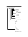
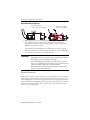
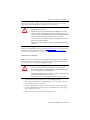
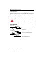
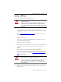
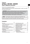
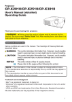
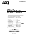
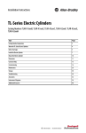
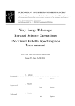
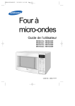
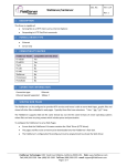
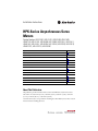
Installation Instructions
HPK-Series Asynchronous Servo
Motors
Catalog Numbers HPK-B1307, HPK-E1307, HPK-B1308, HPK-E1308,
HPK-B1310, HPK-E1310, HPK-B1609, HPK-E1609, HPK-B1611, HPK-E1611,
HPK-B1613, HPK-E1613, HPK-B1815, HPK-E1815, HPK-B2010, HPK-E2010,
HPK-B2212C, HPK-E2212C, HPK-B2510C
Topic
Page
Important User Information
2
Motor Catalog Number Identification
3
Before You Begin
4
Installation and Maintenance Guidelines
4
Installing an HPK Motor
11
Product Dimensions
15
Motor Connectors
26
Load Force Capacities
27
Troubleshooting and Maintenance
29
Shaft Key Removal and Installation
32
Motor Cables and Accessory Kits
33
Specifications
33
Additional Resources
34
About This Publication
This publication provides installation instructions for the HPK-Series asynchronous motors
with a frame size of 1307 mm (51.5 in.), 1600 mm (63.0 in.), 1815 mm (71.5 in.), 2010 mm
(79.1 in.), 2212 mm (86.7 in.), or 2510 mm (98.8 in.).
Use this document if you are responsible for installing these Allen-Bradley motors. Please read all
instructions before installing this motor.
2
HPK-Series Asynchronous Servo Motors
Important User Information
Solid state equipment has operational characteristics differing from those of electromechanical equipment.
Safety Guidelines for the Application, Installation and Maintenance of Solid State Controls, publication
SGI-1.1, is available from your local Rockwell Automation sales office or online at
http://www.rockwellautomation.com/literature. It describes some important differences between solid state
equipment and hard-wired electromechanical devices. Because of this difference, and also because of the
wide variety of uses for solid state equipment, all persons responsible for applying this equipment must
satisfy themselves that each intended application of this equipment is acceptable.
In no event will Rockwell Automation, Inc. be responsible or liable for indirect or consequential damages
resulting from the use or application of this equipment.
The examples and diagrams in this manual are included solely for illustrative purposes. Because of the many
variables and requirements associated with any particular installation, Rockwell Automation, Inc. cannot
assume responsibility or liability for actual use based on the examples and diagrams.
No patent liability is assumed by Rockwell Automation, Inc. with respect to use of information, circuits,
equipment, or software described in this manual.
Reproduction of the contents of this manual, in whole or in part, without written permission of Rockwell
Automation, Inc., is prohibited.
Throughout this manual, when necessary, we use notes to make you aware of safety considerations.
WARNING: Identifies information about practices or circumstances that
can cause an explosion in a hazardous environment, which may lead to
personal injury or death, property damage, or economic loss.
ATTENTION: Identifies information about practices or circumstances
that can lead to personal injury or death, property damage, or economic
loss. Attentions help you to identify a hazard, avoid a hazard, and
recognize the consequences.
SHOCK HAZARD: Labels may be located on or inside the equipment, for
example, a drive or motor, to alert people that dangerous voltage may be
present.
BURN HAZARD: Labels may be located on or inside the equipment, for
example, a drive or motor, to alert people that surfaces may be dangerous
temperatures.
IMPORTANT
Identifies information that is critical for successful application and
understanding of the product.
Publication HPK-IN001C-EN-P - June 2010
HPK-Series Asynchronous Servo Motors
3
Motor Catalog Number Identification
HPK - B 1307 C- S A 4 2 A A
FACTORY DESIGNATED OPTIONS
A
= Standard
MOUNTING TYPE/SHAFT KEY
A
= IEC Metric, Free Mounting Holes
(Type FF), Foot and Flange Mount,
Keyed Shaft
B
= IEC Metric, Free Mounting Holes
(Type FF), Foot Mount Only, Keyed
Shaft
BRAKE
2
= No Brake
4
= 380…460V ac Brake
CONNECTORS
4
= Right-angle Rotatable
BLOWER/JUNCTION BOX
A
= Inline Blower, F3 Jx Box
B
= Top-mount Blower, F1 Jx Box
C
= Top-mount Blower, F2 Jx Box
FEEDBACK
M
= Multi-turn High Resolution Encoder
S
= Single-turn High Resolution Encoder
RATED SPEED (rpm)
C
= 1500
E
= 3000
FRAME SIZE (mm)
1307
1308
1310
1609
1611
1613
1815
2010
2212
2510
VOLTAGE RATING
B
= 460V ac
E
= 400V ac
BULLETIN
HPK
= Asynchronous Servo
Publication HPK-IN001C-EN-P - June 2010
4
HPK-Series Asynchronous Servo Motors
Before You Begin
Before unpacking the product, inspect the shipping carton for damage. If damage is visible,
immediately contact the shipper and request assistance. Otherwise, proceed with unpacking.
Remove the motor carefully from its shipping container, and visually inspect the motor for any
damage. Carefully examine the motor frame, front output shaft, and mounting pilot for any
defects.
Motors are shipped with wooden blocking to prevent axial movement of the shaft during
shipment. Remove the blocking and bolts securing it and verify that the motor shaft turns freely.
If motor is to be shipped or placed in long-term storage, blocking of the bearing is recommended.
Keep the original packing material in case you need to return the product for repair or to
transport it to another location. Use both the inner and outer packing cartons to provide
adequate protection for a unit returned for service.
ATTENTION: Do not attempt to open and modify the motor. Modifications that
can be performed in the field are described in this manual; other changes
should not be attempted.
Only a qualified Allen-Bradley employee can service this type of motor.
Failure to observe these safety procedures could result in personal injury or
damage to equipment.
Installation and Maintenance Guidelines
The guidelines in this section provide you with information about installing servo motor so it
provides safe and reliable service.
Handling
Exercise care when lifting the motor. Always lift in the direction intended in the design of the
lifting mechanism, and lift using all of the eyebolts or lifting lugs provided.
ATTENTION: Eyebolts or lifting lugs are intended for lifting only the motor and
factory mounted accessories.
Do not mount additional equipment before lifting and securing the motor.
Failure to observe this precaution could result in bodily injury.
The angle of lift formed by a lifting rope or chain must be greater than 45 degrees from
horizontal. Diagrams are provided that show proper rigging and lift practices.
Publication HPK-IN001C-EN-P - June 2010
HPK-Series Asynchronous Servo Motors
5
Take precautions during a lift to prevent hazardous overload due to deceleration, acceleration, or
shock forces caused by abrupt raising or lowering, or swinging and twisting of a suspended
motor.
ATTENTION: Eyebolts may unscrew during lifting. Prior to lifting, check the
eyebolts to verify that they are tight and attach lifting equipment to restrict
turning during the lift. Alternatively, lift the unit on a platform or with a sling.
Failure to observe this precaution could result in bodily injury.
Lifting Guidelines
45°
>1/ 2 A
A
For unusual conditions, such as side-wall and ceiling mounting of horizontal motors and
installation of vertical motors shipped in a horizontal position, special precautions must be
taken. We recommend that an experienced rigger be employed.
To Prolong Motor Life
Thoughtful design and proper maintenance can increase the life of a servo motor. The following
are guidelines to maximize the life of a servo motor.
• Always provide a drip loop in a cable to reduce the potential for moisture related
problems. A drip loop is a downward bend in the cable that lets water gather and drip off
the cable rather than continue to flow along the cable.
• Avoid installing the motor with the shaft pointing upward. This orientation increases
the risk of contaminant ingress.
• Environmentally-sealed connectors and cables are required to achieve an International
Protection (IP) rating of IP54 for the motor.
Publication HPK-IN001C-EN-P - June 2010
6
HPK-Series Asynchronous Servo Motors
Cable Orientation for Drip Loop
Cables enter from below.
A drip loop is formed in each cable.
Cables enter from above.
Drip loops are not formed.
• Brakes on these servo motors are holding brakes. The brakes are spring-set, and release
when voltage is applied to the brake coil. A separate power source is required to
disengage the brake. This power source may be applied by a servo motor controller, in
addition to manual operator control.
If system main power fails, holding brakes can withstand occasional use as stopping
brakes. However, this creates rotational mechanical backlash that is potentially damaging
to the machine, increases brake wear, and reduces brake life.
IMPORTANT
Holding brakes are not designed to stop rotation of the motor shaft, nor are
they intended to be used as a safety device. They are designed to hold a motor
shaft at 0 rpm for up to the rated brake holding torque.
The recommended method of preventing motor shaft rotation is a four step
process: first - command the servo drive to 0 rpm; second - verify the motor is at
0 rpm; third - engage the brake; and fourth - disable the drive.
Disabling the drive removes the potential for brake wear caused by a badly
tuned servo system oscillating the shaft.
Mechanical Connections
Mechanical connections to the motor shaft, such as couplings and pulleys, require a torsionally
rigid coupling or a reinforced timing belt. The high dynamic performance of servo motors can
cause couplings, pulleys, or belts to loosen or slip over time. A loose or slipping connection will
cause system instability and may damage the motor shaft. All connections between the machine
and the motor shaft must be rigid to achieve acceptable system response. Periodically inspect
connections to verify their rigidity.
Publication HPK-IN001C-EN-P - June 2010
HPK-Series Asynchronous Servo Motors
7
When mounting couplings or pulleys to the shaft, verify that the connections are properly
aligned and that axial and radial loads are within the motor specifications.
ATTENTION: Do not strike the shaft, key, couplings, or pulleys with tools
during installation or removal.
Damage may occur to the motor bearings and the feedback device if sharp
impact to the shaft is applied during installation of couplings and pulleys, or a
shaft key. Damage to the feedback device also may result by applying leverage
from the faceplate to remove devices mounted on the motor shaft.
To remove a friction-fit or stuck device, apply a constant pressure to the user
end of the shaft with a wheel puller.
Failure to observe these procedures could result in damage to the motor and its
components.
A shaft key provides a rigid mechanical connection with the potential for self-alignment, but the
key must be properly installed in the keyway. The Product Dimensions section provides sizing
information on the key and shaft keyway. Refer to the Shaft Key Removal and Installation
section for recommendations on how to remove and install a shaft key.
Requirements for Mounting
HPK-Series asynchronous motors have a mounting pilot for aligning the motor on a machine.
The installation must comply with all local regulations and use of equipment and installation
practices that promote electromagnetic compatibility and safety.
ATTENTION: Unmounted motors, disconnected mechanical couplings, loose
shaft keys, and disconnected cables are dangerous if power is applied.
Disassembled equipment should be appropriately identified (tagged-out) and
access to electrical power restricted (locked-out).
Before applying power to the motor, remove the shaft key and other mechanical
couplings that could be thrown from the shaft.
Failure to observe these safety procedures could result in personal injury.
• The motor shaft and the load shaft must be parallel and pulleys aligned.
• Pulleys, gears, and similar devices should be mounted as close as practical to the front
motor bearing to minimize bearing load.
• Flexible couplings may be used between the motor shaft and a load shaft. The motor
shaft and load shaft must be aligned to values recommended for the specific coupling
before coupling is connected.
• Stainless steel fasteners are preferred for mounting the motor.
Publication HPK-IN001C-EN-P - June 2010
8
HPK-Series Asynchronous Servo Motors
Allow sufficient clearances in the area of the motor for it to stay within its specified operating
temperature range. Refer to Specifications for the operating range. Do not install the motor in an
area with restricted airflow. Keep other heat producing devices away from the motor.
IMPORTANT
Sufficient clearance must be provided on all inlet and outlet openings to
provide for unrestricted flow of air. Allow at least 152 mm (6.0 in.) of clearance
between the blower exhaust opening and adjacent walls or floor.
Recommended mounting bolts and the torque values are listed below.
Motor
Hole
Diameter
HPK-B and HPK-E
mm (in.)
1307
12 (0.47)
1308
1310
15 (0.60)
1609
1611
Recommended Torque
Bolt Grade 8.8
Bolt Grade 12.9
N•m (lbs.)
N•m (lbs.)
M10-1.5
8.8 (78)
12.9 (114)
M10-1.5
50 (442)
72 (637)
M12-1.75
126 (1115)
158 (1398)
M16-2.5
238 (2106)
337 (2983)
M16-2.5
420 (3717)
596 (5275)
M22-2.5
658 (5823)
934 (8266)
M10-1.75
19 (0.75)
1613
1815
Bolt Size
and
Thread
24 (0.95)
2010
M22-2.5
2212
19 (0.75)
M16-2.5
420 (3717)
596 (5275)
2510
21 (0.81)
M20-2.5
495 (4381)
920 (8142)
Refer to Load Force Capacities to determine the radial and axial shaft load limitations of your
motor.
Publication HPK-IN001C-EN-P - June 2010
HPK-Series Asynchronous Servo Motors
9
Interconnect Cables
Knowledgeable cable routing improves system electromagnetic compatibility (EMC). Refer to
Grounding of Signal Wire Shields Within a Cable for suggested cable trim lengths, and for cable
shield grounding at the motor frame.
IMPORTANT
The recommended wire size is based on motor current requirements and
terminal block sizing. Consult your local electrical code before selecting wire
gauge for your application
To install the cables:
• Keep wire lengths as short as physically possible.
• Route signal cables away from motor and power wiring. Typical signal cables transmit
encoder, serial, or analog data at low voltages.
• Separate cables by 0.3 m (1 ft) minimum for every 9 m (30 ft) of parallel run.
• Ground both ends of the cable shield and twist the signal wire pairs to prevent
electromagnetic interference from other equipment.
ATTENTION: High voltage can be present on power cable shielding, if the
shielding is not grounded.
Verify there is a connection to ground for all power cable shielding.
Failure to observe these safety procedures could result in personal injury or
damage to equipment.
Electrical Noise
Electromagnetic interference (EMI), commonly called noise, may adversely impact motor
performance by inducing stray signals. Effective techniques to counter EMI include filtering the
ac power, shielding and separating signal carrying lines, and practicing good grounding
techniques. Effective ac power filtering can be achieved by using isolated ac power transformers
or properly installed ac line filters. The effect of EMI on motor signals can be minimized by two
installation practices.
• Physically separate signal lines from motor cabling and power wiring. Do not route
signal wires with motor and power wires, and do not route signal wires over the vent
openings of servo drives or other electrical power sources.
• Ground all equipment using a single-point parallel ground system that employs ground
bus bars or large straps. If necessary, use additional electrical noise reduction techniques
to reduce EMI in a noisy environment.
Publication HPK-IN001C-EN-P - June 2010
10
HPK-Series Asynchronous Servo Motors
Power Cable Shielding
HPK-Series motors with brakes integrate the brake signals (BR+ and BR-) with the 380…460V
power at the terminal block. The separate shield surrounding the brake signals must be grounded
to the overall system ground. To properly ground the brake ground shield, or any separately
shielded signal, follow these wiring guidelines.
Verify each cable shield connects to the overall chassis ground by routing as shown in diagram.
Clamp all shields together at the power cable (chassis) ground connection on the drive.
ATTENTION: High voltage can be present on the shields of a power cable, if
the shields are not grounded.
Verify that there is a connection to ground for each shield in the power cable.
Failure to observe these safety procedures could result in personal injury or
damage to equipment.
Power Cable Shielding
Cable as Supplied
}
Two Shielded Signal Wires within Cable
Overall Cable Shield
Cable Field Modified
Signal Shield (one of two)
Customer loops to contact Overall Cable Shield.
Attach to Cable Ground Clamp on Drive
Clamp must contact all cable shields.
Publication HPK-IN001C-EN-P - June 2010
HPK-Series Asynchronous Servo Motors
11
Installing an HPK Motor
Observe the following when installing an HPK-Series motor.
ATTENTION: Do not strike the shaft, couplings, or pulleys with tools during
installation or removal.
Damage may occur to the motor bearings and the feedback device if sharp
impact to the shaft is applied during installation of couplings and pulleys.
Failure to observe these procedures could result in damage to the motor and its
components.
1. Rotate the wiring junction box and position the motor so the junction box may be
accessed for initial wiring and occasional verification of and maintenance to the wiring
connections.
Refer to Cable Orientation for Drip Loop on page 6 for a visual reference of correct
motor and cable positioning.
2. Properly mount the motor.
Refer to the motor outline drawings for dimensions. If necessary, shim the motor to
achieve proper alignment of the shaft.
3. Align the motor shaft on the index pulse.
The index pulse occurs on a single-turn encoder when the shaft key is aligned with the
top of the motor. Refer to the motor outline drawings for a visual reference of this
alignment.
4. Form a drip loop in the cables directly before each cable enters the motor.
A drip loop lets liquids gather and drip off the cable rather than flow along the cable to
an electrical connection or the motor. Refer to Cable Orientation for Drip Loop on
page 6 for a visual example.
ATTENTION: Be sure that feedback cable is installed and restrained to
prevent uneven tension or flexing at the cable connector.
Excessive and uneven lateral force at the feedback connector may result in the
connector’s environmental seal opening and closing as the cable flexes.
Failure to observe these safety procedures could result in damage to the motor
and its components.
5. Remove the access cover on the junction box, and rotate the box in 90° increments to
improve cable access.
Publication HPK-IN001C-EN-P - June 2010
12
HPK-Series Asynchronous Servo Motors
6. Route power cables into the junction box.
The recommended wire size is based on motor current requirements and
terminal block sizing. Consult your local electrical code before selecting wire
gauge for your application.
IMPORTANT
The table lists the access hole diameters for the junction box, and the maximum width of
the wire terminal inside the junction box.
Motor Catalog No.
HPK-x1307, HPK-x1308, HPK-x1310
Dia. A, Max.
Dia. B, Max.
Wire Terminal
Max Width
mm (in.)
mm (in.)
mm (in.)
35 (1.4)
21 (0.84)
19 (0.75)
HPK-x1609, HPK-x1611, HPK-x1613
45 (1.8)
20 (0.825)
HPK-x1815, HPK-x2010, HPK-x2212,
HPK-B2510 (1)
Blank access plate
63.5 (2.5) spacing of
copper bus bars
(1)
Wire selection and access port sizing are determined and performed by the end user as they are application dependent.
The diagram below depicts the threaded access ports on the HPK-x13xx and
HPK-x16xx motors, and the connector block or terminal strip connections.
ATTENTION: Unshielded power connections should not extend beyond the
terminal block body.
Failure to observe these safety procedures could result in damage to the motor,
cables, and connector components.
HPK-x13xx and HPK-x16xx Power Cable Access and Wiring
Dia. A
External View of
Junction Box Showing
Access Port Locations
Dia. B
Ground and Shield
Connect to Lug
U
V
W
Internal View of
Junction Box Showing
Terminal Block Wiring
To HPK Motor
Terminal Blocks
Max. Width
of Wire
Terminal
LINE 1
Publication HPK-IN001C-EN-P - June 2010
LINE 2
LINE 3
From Input Power
HPK-Series Asynchronous Servo Motors
13
7. Connect the power cable leads (U/T1, V/T2, and W/T3) to the power terminals.
8. Connect the ground and shield connect to the ground lug.
AC Input to Motor
Connect Input
with Wire Color
to Terminal
M8 Clamping
Bolt Torque
M6 Cover
Threaded Bolt
Torque
Line 1
Black
U/T1
14 N•m (1.6 lb-in.)
8 N•m (0.9 lb-in.)
Line 2
Blue
V/T2
Line 3
Brown
W/T3
Ground
Green/Yellow
GND
Shield
Yellow/Green
9. Connect the other end of the power cable to the three-phase 380…460V AC power
outputs on the controller as described in the instruction manual for that device.
ATTENTION: The motor is at line voltage when ac power is connected.
Disconnect and lockout all ungrounded conductors of the ac power line before
attempting any to connect or disconnect power wiring at the motor.
Failure to observe these precautions could result in severe bodily injury or loss
of life.
Proper grounding of power cable shielding is essential for error-free operation. Refer to
the instruction manual of your drive for recommended grounding techniques.
10. Connect blower leads to the three-phase 380…460V ac power source as outlined in the
table below and shown in the Blower Wiring Diagrams on page 14.
AC Input to Blower (380…460V)
Connect Input
with Wire Color
to Terminal
Line 1
Black
U
Line 2
Blue
V
Line 3
Brown
W
Ground
Green/Yellow
GND
Publication HPK-IN001C-EN-P - June 2010
14
HPK-Series Asynchronous Servo Motors
Blower Wiring Diagrams
DELTA
T6
T4
T1
STAR
T5
T2
L1
L2
T3
L3
Low Volts Line
W2
U2
U1
L1
L2
T4
T5
T1
T2
T3
L1
L2
L3
High Volts Line
V2
V1
T6
W1
L3
Low Volts Line
W2
U2
V2
U1
V1
W1
L1
L2
L3
High Volts Line
U1 = Black
V1 = Blue
W1 = Brown
U2 = Green
V2 = White
W2 = Yellow
11. Attach the feedback cable to the motor as follows:
ATTENTION: Keyed connectors must be properly aligned and hand-tightened
the recommended number of turns.
Improper connector alignment is indicated by the need for excessive force,
such as the use of tools, to fully seat connectors.
Failure to observe these safety procedures could result in damage to the motor,
cables, and connector components.
a. Carefully align the feedback cable connector with the respective motor connector.
b. The flat surface with logo on each connector should align. Do not apply excessive
force when mating the cable and motor connectors. If the connectors do not go
together with light hand force, realign and try again.
c. Fully seat the feedback connector by hand tightening the knurled collar five to six
turns until resistance is felt.
12. Perform the Troubleshooting and Maintenance procedures listed below that are
appropriate to your installation.
•
•
•
•
Bearing Inspection
Periodic Lubrication
Grease and Repack Bearings
Shaft Key Removal and Installation
Publication HPK-IN001C-EN-P - June 2010
HPK-Series Asynchronous Servo Motors
15
Product Dimensions
The figures show dimension symbols for the HPK-Series motors, and these dimensions are
provided in tables.
Motors are designed to metric dimensions. Inch dimensions are approximate
conversions from millimeters. Dimensions without tolerances are for reference.
TIP
HPK-Series Motor (Non-brake) Dimensions (HPK-B/E13xx and HPK-B/E16xx)
Junction box rotates in 90° increments.
F3 mount (top) location is shown.
Airflow
Clearance
Required
LA
Encoder
Connector
T
N
BD
BE
EA
C
B
E
B1
B2
BA
BB
BC
C1
L
Shaft Diameter Tolerances:
HPK-B/E 1307, 1308, 1310
Ø 48.003…48.016 (1.8899…1.8904)
HPK-B/E 1609, 1611, 1613
Ø 55.011…55.030 (2.1658…2.1665)
F
D
G GA
Shaft Key:
HPK-B/E 1307, 1308,
1310 = 14 X 9 X 80
HPK-B/E 1609, 1611,
1613 = 16 X 10 X 90
HB
P
H
S = Diameter of Holes
M = Diameter of Bolt Circle
Pilot Diameter Tolerances:
HPK-B/E 1307, 1308, 1310
Ø 249.99…250.02 (9.842…9.844)
HPK-B/E 1609, 1611, 1613
Ø 299.99…300.02 (11.809…11.811)
HC
HD
A
AB
AC
K
Publication HPK-IN001C-EN-P - June 2010
16
HPK-Series Asynchronous Servo Motors
HPK-Series Motor (Non-brake) Dimensions (HPK-B/E13xx and HPK-B/E16xx)
Motor Series
A
AA
AB
AC
B
B1
B2
BA
HPK-B/E
mm (in.)
mm (in.)
mm (in.)
mm (in.)
mm (in.)
mm (in.)
mm (in.)
mm (in.)
1307
216
(8.50)
108
(4.25)
260
(10.2)
279
(10.9)
333
(13.1)
365
(14.3)
390
(15.3)
154
(6.06)
1308
371
(14.6)
403
(15.8)
428
(16.8)
1310
403
(15.8)
435
(17.1)
462
(18.1)
N/A
414
(16.3)
452
(17.8)
1611
N/A
464
(18.2)
502
(19.7)
1613
N/A
515
(20.2)
548
(21.5)
1609
254
(10.0)
127
(5.0)
313
(12.3)
332
(13.0)
170
(6.69)
Motor Series
BB
BC
BD
BE
C
C1
D
E
HPK-B/E
mm (in.)
mm (in.)
mm (in.)
mm (in.)
mm (in.)
mm (in.)
mm (in.)
mm (in.)
1307
187
(7.36)
95.0
(3.74)
91.0
(3.58)
300
(11.8)
89.0
(3.50)
57.0
(2.24)
48.0
(1.89)
110
(4.33)
1308
226
(8.90)
338
(13.3)
1310
257
(10.1)
369
(14.5)
1609
225
(8.86)
108
(4.25)
82.0
(3.23)
55.0
(2.16)
110
(4.33)
1611
276
(10.8)
1613
327
(12.8)
95.0
(3.74)
130
(5.12)
321
(12.6)
372
(14.6)
125
(4.92)
Publication HPK-IN001C-EN-P - June 2010
423
(16.6)
HPK-Series Asynchronous Servo Motors
17
HPK-Series Motor (Non-brake) Dimensions (HPK-B/E13xx and HPK-B/E16xx)
Motor Series
EA
F
G
GA
H
HB
HC
HD
HPK-B/E
mm (in.)
mm (in.)
mm (in.)
mm (in.)
mm (in.)
mm (in.)
mm (in.)
mm (in.)
1307
52.0
(2.05)
13.9
(0.55)
42.4
(1.67)
51.3
(2.02)
366
(14.4)
53.0
(2.09)
262
(10.3)
132
(5.20)
52.0
(2.05)
16.0
(0.63)
48.5
(1.91)
58.7
(2.31)
444
(17.4)
62.0
(2.44)
316
(12.4)
160
(6.30)
1308
1310
1609
1611
450
(17.7)
1613
Motor Series
K
L
LA
M
N
P
S (1)
T
HPK-B/E
mm (in.)
mm (in.)
mm (in.)
mm (in.)
mm (in.)
mm (in.)
mm (in.)
mm (in.)
1307
12.0
(0.47)
806
(31.7)
17.0
(0.67)
300
(11.8)
250
(9.84)
350
(13.7)
18.5
(0.73)
5.0
(0.20)
21.0
(0.83)
350
(13.7)
300
(11.8)
400
(15.7)
18.5
(0.73)
5.0
(0.20)
1308
845
(33.2)
1310
876
(34.4)
1609
14.0
(0.55)
886
(34.8)
1611
937
(36.8)
1613
987
(38.8)
(1)
Tolerance for this dimension is +0.52, -0.0 mm (+0.02, -0.0 in.)
Publication HPK-IN001C-EN-P - June 2010
18
HPK-Series Asynchronous Servo Motors
HPK-Series Motor (Brake) Dimensions (HPK-B/E13xx and HPK-B/E16xx)
LD
Airflow
Clearance
Required
Encoder
Connector
J1
B
B1
L
AD
AE
AF
H
Junction box rotates in
90° increments.
F1 mount (left side)
location is shown.
F2 mount (right side)
is available.
J2
Publication HPK-IN001C-EN-P - June 2010
HPK-Series Asynchronous Servo Motors
19
HPK-Series Motor (Brake) Dimensions (HPK-B/E13xx and HPK-B/E16xx)
Motor Series
AD
AE
AF
BE
H
J1
J2
L
LD
HPK-B/E
mm
(in.)
mm
(in.)
mm
(in.)
mm
(in.)
mm
(in.)
mm
(in.)
mm
(in.)
mm
(in.)
mm
(in.)
1307
247
(9.72)
236
(9.29)
195
(7.68)
298
(11.7)
588
(23.1)
190
(7.48)
196
(7.72)
888
(34.9)
336
(13.2)
1308
336
(13.2)
926
(36.4)
1310
368
(14.5)
957
(37.7)
1609
285
(11.2)
236
(9.29)
225
(8.86)
328
(12.9)
670
(26.3)
224
(8.82)
228
(8.98)
967
(38.0)
1611
379
(14.9)
1018
(40.1)
1613
430
(16.9)
1069
(42.1)
332
(13.0)
Publication HPK-IN001C-EN-P - June 2010
20
HPK-Series Asynchronous Servo Motors
HPK-Series Motor (Non-brake) Dimensions (HPK-B/E1815 and HPK-B/E2010)
Airflow
Clearance
Required
Junction box rotates in 90° increments
F3 mount (top) location is shown.
Encoder
Connector
BD
BC
BB
C
B
BA
E
L
EA
Shaft Diameter Tolerance
HPK-B1815 HPK-E1815 motors:
Ø 70.007...70.033 (2.7562...2.7572)
HPK-B2010 HPK-E2010 motors:
Ø 80.007...80.033 (3.1500...3.1507)
C1
F
D
Shaft Key:
HPK-B/E1815 = 14 x 9 x 80
HPK-B/E2010 = 16 x 10 x 90
G GA
J1
J3
HPK-B/E2010C-x42BA is shown
HB
H
HC
HD
K
A
AB
AC
Publication HPK-IN001C-EN-P - June 2010
HPK-Series Asynchronous Servo Motors
21
HPK-Series Motor (Non-brake) Dimensions (HPK-B/E1815 and HPK-B/E2010)
Motor Series
A
AB
AC
B
BA
BB
BC
BD
HPK-B/E
mm (in.)
mm (in.)
mm (in.)
mm (in.)
mm (in.)
mm (in.)
mm (in.)
mm (in.)
1815
279
(10.9)
350
(13.8)
382
(15.1)
622
(24.5)
670
(26.4)
420
(16.5)
174
(6.85)
476
(18.7)
2010
318
(12.5)
397
(15.6)
403
(15.9)
654
(25.7)
705
(27.7)
420
(16.5)
203
(8.0)
450
(17.7)
Motor Series
C1
D
E
EA
F
G
GA
H
HPK-B/E
mm (in.)
mm (in.)
mm (in.)
mm (in.)
mm (in.)
mm (in.)
mm (in.)
mm (in.)
1815
133
(5.24)
70
(2.76)
140
(5.51)
52.0
(2.05)
19.9
(0.78)
62.5
(2.4)
74.5
(2.9)
514
(20.2)
2010
146
(5.75)
80
(3.15)
170
(6.69)
52.0
(2.05)
22.0
(0.86)
71.0
(2.8)
85
(3.3)
691
(27.2)
Motor Series
HB
HC
HD
J1
J3
K
L
HPK-B/E
mm (in.)
mm (in.)
mm (in.)
mm (in.)
mm (in.)
mm (in.)
mm (in.)
1815
69
(2.72)
360
(16.18)
180
(7.09)
—
—
15
(0.59)
1116
(43.9)
2010
69
(2.72)
400
(15.74)
200
(7.87)
366
(14.4)
123
(4.8)
19
(0.75)
1153
(45.4)
Publication HPK-IN001C-EN-P - June 2010
22
HPK-Series Asynchronous Servo Motors
HPK-Series Motor (Brake) Dimensions (HPK-B/E2010)
LD
Airflow
Clearance
Required
Encoder
Connector
J1
L
HPK-x2010x-x44BA is shown
AD
AE
H
Junction box rotates in
90° increments.
F1 mount (left side)
location is shown.
F2 mount (right side)
is available.
J2
HPK-Series Motor (Brake) Dimensions (HPK-B/E2010)
Motor Series
AD
AE
H
L
HPK-B/E
mm (in.)
mm (in.)
mm (in.)
mm (in.)
mm (in.)
2010
484
(19.0)
360
(14.2)
725
(28.5)
1245
(49.0)
330
(13.0)
Publication HPK-IN001C-EN-P - June 2010
LD
HPK-Series Asynchronous Servo Motors
23
HPK-Series Motor (Non-brake) Dimensions (HPK-B2212C and HPK-B2510C)
Junction box rotates in 90° increments
F3 mount (top) location is shown.
Encoder
Connector
BD
Airflow
Clearance
Required
BC
BB
C
B
BA
E
L
EA
Shaft Diameter Tolerance
HPK-B2212 motor:
Ø 60.010...60.030 (2.3626...2.3624)
HPK-B2510 motor:
Ø 80.007...80.033 (3.1500...3.1507)
C1
F
D
Shaft Key
HPK-B2212 = 18 x 11 x 110
HPK-B2510 = 16 x 10 x 90
G GA
J1
HPK-B2212C-SB44BA shown
HB
H
HC
HD
K
A
AB
AC
Publication HPK-IN001C-EN-P - June 2010
24
HPK-Series Asynchronous Servo Motors
HPK-Series Motor (Non-brake) Dimensions (HPK-B2212C and HPK-B2510C)
Motor Series
A
AB
AC
B
BA
BD
C
D
HPK-B
mm (in.)
mm (in.)
mm (in.)
mm (in.)
mm (in.)
mm (in.)
mm (in.)
mm (in.)
2212
356
(14.0)
445
(17.5)
476
(18.7)
806
(31.7)
864
(34.0)
588
(23.1)
156
(6.13)
60
(2.36)
2510
406
(16.0)
497
(19.6)
533
(21.0)
775
(30.5)
838
(33.0)
695
(27.4)
162
(6.4)
Motor Series
E
EA
F
G
GA
H
HB
HC
HPK-B
mm (in.)
mm (in.)
mm (in.)
mm (in.)
mm (in.)
mm (in.)
mm (in.)
mm (in.)
2212
140
(5.5)
254
(10.0)
18
(0.7)
53
(2.0)
64
(2.5)
738
(29.0)
71
(2.8)
447
(17.6)
812
(32.0)
90
(3.5)
502
(19.8
2510
351
(13.8)
Motor Series
HD
J1
K
L
HPK-B
mm (in.)
mm (in.)
mm (in.)
mm (in.)
2212
225
(8.8)
526
(20.7)
19
(0.75)
1278
(50.3)
2510
254
(10.0)
583
(22.9)
21
(0.81)
1327
(52.3)
Publication HPK-IN001C-EN-P - June 2010
HPK-Series Asynchronous Servo Motors
25
HPK-Series Motor (Brake) Dimensions (HPK-B2212C)
LD
Airflow
Clearance
Required
Encoder
Connector
L
HPK-B2212C-SB44BA is shown
AD
AE
H
Junction box rotates
in 90° increments.
F1 mount (left side)
location is shown.
F2 mount (right side)
is available.
HPK-Series Motor (Brake) Dimensions (HPK-B2212C)
Motor Series
AD
AE
H
L
LD
HPK-B/E
mm (in.)
mm (in.)
mm (in.)
mm (in.)
mm (in.)
2212
521
(20.5)
396
(15.6)
816
(32.1)
1372
(54.0)
383
(15.0)
Publication HPK-IN001C-EN-P - June 2010
26
HPK-Series Asynchronous Servo Motors
Motor Connectors
The tables below contains connector and terminal block descriptions for the feedback
connector, and the combined HPK-Series power and brake connector.
Feedback
Pin
Power
2000 Line Encoder
High Resolution
Encoder
Signal
Signal
Terminal
Description
1
Sin+
Sin+
P1
Thermostat Lead
2
Sin-
Sin-
P2
Thermostat Lead
3
Cos+
Cos+
U/R (1)
4
Cos-
Cos-
5
Data+
Data+
6
Data-
Data-
7
Reserved
Reserved
V /S
(1)
W/T
(1)
Line 1
Line 2
Line 3
Ground
8
9
+5V DC
Brake
10
Common
Signal
Description
11
Reserved
+9V DC
BR+
Brake
Common
BR-
12
13
TS+
TS+
14
TS-
TS-
15
Reserved
Reserved
16
17
11
8
2
13
16
9
1
12
10
15
7
3
17 14
4
6
5
Intercontec P/N
AKUA034MR04120035000
(1)
U, V, and W power phases may be labelled as R, S, and T respectively.
Publication HPK-IN001C-EN-P - June 2010
HPK-Series Asynchronous Servo Motors
27
Load Force Capacities
This section contains the radial and axial motor load-force ratings for HPK-Series motors. These
motors are capable of operating with the maximum radial or maximum axial shaft loads listed in
the following tables. Radial loads listed are applied in the middle of the shaft extension.
Shaft Loading HPK-Series Motor Load Forces
Radial load force applied
at center of shaft extension
Axial load force
The tables below represent an L10 bearing fatigue life of 10,000 hours. This 10,000-hour life
does not account for possible application-specific life reduction that may occur due to bearing
grease contamination from external sources. Maximum operating speed is limited by motor
winding.
Radial Load-force Ratings (Zero Axial Load)
Motor Series
850 rpm
1150 rpm
1750 rpm
2500 rpm
HPK-
kg (lb)
kg (lb)
kg (lb)
kg (lb)
B/E1307
320 (704)
290 (638)
250 (550)
220 (485)
B/E1308
320 (704)
290 (638)
250 (550)
220 (485)
B/E1310
320 (704)
290 (638)
250 (550)
220 (485)
B/E1609
500 (1100)
450 (990)
390 (858)
350 (770)
B/E1611
500 (1100)
450 (990)
390 (858)
350 (770)
B/E1613
500 (1100)
450 (990)
390 (858)
350 (770)
B/E1815
530 (1166)
530 (1166)
530 (1166)
450 (990)
B/E2010
660 (1452)
660 (1452)
660 (1452)
580 (1276)
B2212
730 (1609)
690 (1521)
600 (1323)
530 (1169)
B2510
670 (1503)
610 (1369)
550 (1234)
480 (1077)
Publication HPK-IN001C-EN-P - June 2010
28
HPK-Series Asynchronous Servo Motors
Axial Load-force Ratings (Zero Radial Load)
Motor Series
850 rpm
1150 rpm
1750 rpm
2500 rpm
HPK-
kg (lb)
kg (lb)
kg (lb)
kg (lb)
B/E1307
260 (572)
240 (528)
210 (462)
180 (396)
B/E1308
260 (572)
240 (528)
210 (462)
180 (396)
B/E1310
260 (572)
240 (528)
210 (462)
180 (396)
B/E1609
360 (796)
330 (726)
290 (638)
250 (550)
B/E1611
360 (796)
330 (726)
290 (638)
250 (550)
B/E1613
360 (796)
330 (726)
290 (638)
250 (550)
B/E1815
440 (970)
380 (838)
310 (682)
260 (572)
B/E2010
530 (1166)
460 (1012)
370 (814)
310 (682)
B2212
800 (1764)
730 (1609)
630 (1389)
560 (1235)
B2510
670 (1504)
610 (1369)
530 (1189)
470 (1055)
Publication HPK-IN001C-EN-P - June 2010
HPK-Series Asynchronous Servo Motors
29
Troubleshooting and Maintenance
Standard troubleshooting and maintenance of this motor requires completion of these tasks:
•
•
•
•
Bearing inspection
Bearing greasing and repacking
Periodic lubrication of a motor
Shaft key removal and installation
BURN HAZARD: Outer surfaces of the motor can reach high temperatures during
motor operation.
Take precautions to prevent accidental contact with hot surfaces. Consider motor
surface temperature when selecting motor mating cable connections.
Failure to observe these safety procedures could result in personal injury or
damage to equipment.
Bearing Inspection
Frequent bearing checks are recommended. If bearing or motor temperatures become excessive,
investigate the cause. Total bearing temperatures should not exceed 90 ºC (194 ºF). Causes of
high bearing temperature are typically due to these conditions.
•
•
•
•
•
•
•
Contaminated grease
Insufficient or excessive amount of grease
Incorrect grease
Excessive load or thrust due to misalignment or motor overload
Loose bearings
Bearing failure
Excessive ambient temperature
Grease and Repack Bearings
Follow this procedure when packing new bearings or repacking bearings after servicing a motor.
1. Apply one continuous bead of grease around the inboard side of the bearing, between
the bearing and the inner cap.
2. Apply one continuous bead of grease around the outboard side of the bearing, between
the bearing and the inner cap.
3. Verify that the grease applied in steps 1 and 2 adheres to the balls or rollers.
4. Completely fill the grease inlet and outlet passage holes with grease.
5. Fill the outboard bearing cavity 60…90% full of grease.
Publication HPK-IN001C-EN-P - June 2010
30
HPK-Series Asynchronous Servo Motors
6. If possible, manually rotate the shaft at least three revolutions to distribute grease within
the bearings before starting the motor.
Periodic Lubrication of HPK-x1815…HPK-x2510 Motors
The HPK-x1815, HPK-x2010, HPK-x2012, HPK-x2212, and HPK-x2510 motor design has a
positive lubrication system for routing new grease directly into the bearing. The tables below
show lubrication periods and amounts for varying service conditions, speeds, bearing types, and
operating hours.
ATTENTION: Lubrication with the shaft stationary and a warm motor is
recommended.
If lubrication must be performed with the motor running, stay clear of rotating
parts and electrical circuits.
Failure to observe these precautions could result in bodily injury.
Lubrication Procedure
Follow these steps to lubricate the motor:
1. Locate the grease inlet at the top of the bearing hub and clean the area.
2. If the motor is not equipped with a grease fitting, replace the pipe plug with a grease
fitting.
3. Remove the grease drain plug opposite the grease inlet.
Grease Port Locations
Back Grease Port or Fitting
Front Grease Port or Fitting
4. Using a manual grease gun, pump in the recommended amount of grease.
5. Replace any temporary grease fittings that were installed, and then wipe away any excess
grease at the grease drain or relief.
6. Replace the drain plugs.
Publication HPK-IN001C-EN-P - June 2010
HPK-Series Asynchronous Servo Motors
31
Lubrication Amounts and Intervals
The tables below list the recommended amount and interval for lubrication of HPK-Series
motors.
Chevron SRI-2 or equivalent grease is recommended, unless the motor nameplate specifies a
special grease.
Catalog Number
Volume
HPK-B or HPK-E
Cubic
Centimeter
1307…1815
Lubricated for life
2010, 2212 or 2510
Weight
Cubic Inches
Grams
Ounces
32
2.0
28
1.0
Service Condition
Ambient
Temperature (2)
Bearing Load
Atmosphere
Operating
Hours per Day
Standard
-18…40 °C
(-0.4…104 °F)
Steady
Clean
8
Severe
-30…50 °C
(-22…122 °F)
Medium Shock,
Vibration
less than 0.2 in/s
Medium Dirt,
Abrasives,
Corrosion
8…24
Extreme (1)
-50…65 °C
(-58…149 °F)
Heavy Shock,
Vibration
greater than 0.44
in/s
Heavy Dirt,
Abrasives,
Corrosion
8…24
(1)
Extreme service conditions are rare in actual practice. corresponding lubrication cycles should therefore be applied with
caution. In addition, it is advisable to check with Rockwell Automation for special instructions.
(2)
Specially designed motors are required for operation in ambient temperatures outside the range of -25…40 °C
(-13…104 °F)
Normal Operating Speed
Lubrication Interval in Months
Max. rpm
Standard Service
Severe Service
Extreme Service
3450 and higher
9
4
1
2400…3449
24
9
3
1700…2399
36
12
3
800…1399
36
24
8
500…799
48
36
12
499 and lower
48
36
12
Publication HPK-IN001C-EN-P - June 2010
32
HPK-Series Asynchronous Servo Motors
Shaft Key Removal and Installation
Shaft keys are dimensioned for an interference fit, slightly larger than the opening. An
interference fit provides a secure and rigid mating connection.
ATTENTION: Do not strike the shaft, key, couplings, or pulleys with tools
during installation or removal.
Damage may occur to the motor bearings and the feedback device if sharp
impact to the shaft is applied during installation of couplings and pulleys, or
a shaft key. Damage to the feedback device also may result by applying
leverage from the faceplate to remove devices mounted on the motor shaft.
Apply a constant pressure, with a wheel puller, to the user end of the shaft
to remove from the motor shaft any friction fit or stuck device.
Failure to observe these safety procedures could result in damage to the
motor and its components.
To Remove a Shaft Key
Lift the key by grasping it with a plier or similar tool, or lever the key with a flat-blade screwdriver
inserted between the key and the slot.
To Install a Shaft Key
1. Verify the replacement key matches the keyway in the shaft and the mating mechanical
connection (for example, a coupling or pulley) before proceeding.
2. Support the motor and shaft to prevent movement.
3. Align the front of the key with the front of the shaft. This prevents the radiused
end-of-cut at the motor end of the keyway from interfering with seating of the key.
Shaft Key Alignment
Radiused Cut for Keyway
Key Alignment
Key
Shaft
4. Apply a constant force across the exposed surface of the key with a controlled press
device (for example, a screw clamp) to push the key into the shaft.
5. Visually inspect the motor and the key to verify the key is fully seated and aligned.
Publication HPK-IN001C-EN-P - June 2010
HPK-Series Asynchronous Servo Motors
33
6. Verify the motor shaft, faceplate, bearing bore, wear sleeve, and keyway are free of nicks,
burrs, grooves, or spiral machine marks.
IMPORTANT
Check the motor shaft and surrounding surfaces. Remove any nicks, burrs, or
surface damage.
Motor Cables and Accessory Kits
Accessories available from the factory include motor feedback cables.
Motor Cables
Factory-manufactured feedback cables are available in standard cable lengths. They provide the
sealing necessary to achieve environmental ratings and the required shield termination. For a
complete listing of available cables, contact your nearest Rockwell Automation sales office or
refer to the Kinetix Motion Control Selection Guide.
Specifications
Always store a motor in a clean and dry location within these environmental conditions.
Appropriate mounting, cabling, and a shaft seal may be required to attain a specific IP rating.
Attribute
Value
0…40 °C (32…104 °F)
Temperature, Operating
Temperature, Storage
(1)
-30…70 °C (-22…158 °F)
Relative Humidity
5…60% noncondensing (4)
Atmosphere
noncorrosive
Shock
10 g peak, 6 ms duration
Vibration
Ingress Protection Code
2.5 g, 30...2000 Hz
(2)
= IP54
(3)
Dust protected, splashing water
Shaft Material
1040/1045 steel
Encoder
Up to 2 million counts per revolution
(1)
Always store a motor in a clean and dry location within these environmental conditions.
(2)
Ingress Protection (IP) ratings are determined by using Rockwell Automation cables to connect to the motor.
(3)
Environmentally-sealed connectors and cables are required to achieve an International Protection (IP) rating of IP54 for the
motor.
(4)
Drain plugs, T-drains, and breathers must be removed or opened to permit breathing. Motors located in a moist environment
must have space heaters to protect against condensation when motor is not operating.
Publication HPK-IN001C-EN-P - June 2010
34
HPK-Series Asynchronous Servo Motors
Additional Resources
For additional information about motors and compatible Rockwell Automation drives, refer to
these publications.
Resource
Description
HPK-Series Motor Encoder Replacement
Installation Instructions, publication HPK-IN002
How to replace the encoder on an HPK motor
Kinetix 7000 Drive Installation Instructions,
publication 2099-IN003
How to install, set up, and troubleshoot a servo-drive
system
Kinetix 7000 Drive User Manual, publication
2099-UM001
Allen-Bradley Industrial Automation Glossary,
publication AG-7.1
A glossary of industrial automation terms and
abbreviations
System Design for Control of Electrical Noise
Reference Manual, publication GMC-RM001
Information, examples, and techniques designed to
minimize system failures caused by electrical noise
Kinetix Motion Control Selection Guide,
publication GMC-SG001
Specifications, motor/servo-drive system combinations,
and accessories for Kinetix motion control products
These publications are available from your local Rockwell Automation office. At the website
http://www.rockwellautomation.com/literature you may download an electronic version of
these publications.
Publication HPK-IN001C-EN-P - June 2010
HPK-Series Asynchronous Servo Motors
35
Notes:
Publication HPK-IN001C-EN-P - June 2010
Rockwell Automation Support
Rockwell Automation provides technical information on the Web to assist you in using its products. At
http://www.rockwellautomation.com/support/, you can find technical manuals, a knowledge base of FAQs,
technical and application notes, sample code and links to software service packs, and a MySupport feature that
you can customize to make the best use of these tools.
For an additional level of technical phone support for installation, configuration and troubleshooting, we offer
TechConnect support programs. For more information, contact your local distributor or Rockwell Automation
representative, or visit http://www.rockwellautomation.com/support/.
Installation Assistance
If you experience a problem within the first 24 hours of installation, please review the information that's
contained in this manual. You can also contact a special Customer Support number for initial help in getting your
product up and running.
United States or Canada 1.440.646.3434
Outside United States
or Canada
Use the Worldwide Locator at
http://www.rockwellautomation.com/support/americas/phone_en.html, or contact
your local Rockwell Automation representative.
New Product Satisfaction Return
Rockwell Automation tests all of its products to ensure that they are fully operational when shipped from the
manufacturing facility. However, if your product is not functioning and needs to be returned, follow these
procedures.
United States
Contact your distributor. You must provide a Customer Support case number (call the
phone number above to obtain one) to your distributor to complete the return process.
Outside United States
Please contact your local Rockwell Automation representative for the return
procedure.
Documentation Feedback
Your comments will help us serve your documentation needs better. If you have any suggestions on how to
improve this document, complete this form, publication RA-DU002, available at
http://www.rockwellautomation.com/literature/.
Allen-Bradley, Kinetix, Rockwell Software, Rockwell Automation, and TechConnect are trademarks of Rockwell Automation, Inc.
Trademarks not belonging to Rockwell Automation are property of their respective companies.
Rockwell Otomasyon Ticaret A.Ş., Kar Plaza İş Merkezi E Blok Kat:6 34752 İçerenköy, İstanbul, Tel: +90 (216) 5698400
Publication HPK-IN001C-EN-P - June 2010
Supersedes Publication HPK-IN001B-EN-P - June 2006
PN-80103
Copyright © 2010 Rockwell Automation, Inc. All rights reserved. Printed in the U.S.A.