1
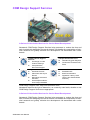
User Manual
SOM-6760
Copyright
This document is copyrighted, © 2008. All rights are reserved. The original manufacturer reserves the right to make improvements to the products described in this manual at any time without notice.
No part of this manual may be reproduced, copied, translated or transmitted in any
form or by any means without the prior written permission of the original manufacturer. Information provided in this manual is intended to be accurate and reliable.
However, the original manufacturer assumes no responsibility for its use, nor for any
infringements upon the rights of third parties that may result from such use.
Trademarks
Award is a trademark of Award Software International, Inc.
VIA is a trademark of VIA Technologies, Inc.
IBM, PC/AT, PS/2 and VGA are trademarks of International Business Machines Corporation.
Intel and Pentium are trademarks of Intel Corporation.
Microsoft Windows® is a registered trademark of Microsoft Corp.
RTL is a trademark of Realtek Semi-Conductor Co., Ltd.
ESS is a trademark of ESS Technology, Inc.
UMC is a trademark of United Microelectronics Corporation.
SMI is a trademark of Silicon Motion, Inc.
Creative is a trademark of Creative Technology LTD.
CHRONTEL is a trademark of Chrontel Inc.
All other product names or trademarks are properties of their respective owners.
SOM-6760 User Manual
Part No. 2006676000
Edition 1
Printed in Taiwan
March 2009
ii
Product Warranty (2 years)
Warranty Period
ADVANTECH aims to meet the customer’s expectations for post-sales service and
support; therefore, in addition to offering 2 years global warranty for ADVANTECH’s
standard products, a global extended warranty service is also provided for customers
upon request. ADVANTECH customers are entitled to a complete and prompt repair
service beyond the standard 2 years of warranty.
Standard products manufactured by ADVANTECH are covered by a 2 year global
warranty from the date of shipment. Products covered by extended warranty and
cross-region repair services against defects in design, materials, and workmanship,
are also covered from the date of shipment. All key parts assembled into ADVANTECH system products such as LCD, Touch Screen, Power Supply, and peripherals
etc, will be also covered by the standard 2 year warranty.
Repairs under Warranty
It is possible to obtain a replacement (Cross-Shipment) during the first 30 days of
purchase (45 days for Channel Partners), if the products were purchased directly
from ADVANTECH and the product is DOA (Dead-on-Arrival).
DOA Cross-Shipment excludes any customized and/or build-to-order products. The
Cross-Shipment agreement signed by customers is required for initiating/releasing
cross shipment with ADVANTECH confirmation and verification. The only conditions
for Cross-Shipment are: a) the return must not be damaged, altered or marked, b) all
parts and accessories must be included as originally shipped; and c) proof of purchase must be included. Any returns that do not meet mentioned requirements
above, or any wrong user settings/configurations will be denied, or subject to additional handling/service charges as determined by the ADVANTECH Repair Service
Department.
For those products which are not DOA, the return fee to an authorized ADVANTECH
repair facility will be at the customers’ expense. The shipping fee for reconstructive
products from ADVANTECH back to customers’ sites will be at ADVANTECH°Øs
expense.
Exclusions from Warranty
The product is excluded from warranty if:
The product has been found to be defective after expiry of the warranty period.
Warranty has been voided by removal or alternation of product or part identification labels.
The product has been misused, abused, or subjected to unauthorized disassembly/modification; placed in an unsuitable physical or operating environment;
improperly maintained by the customer; or failure caused which ADVANTECH is
not responsible whether by accident or other cause. Such conditions will be
determined by ADVANTECH at its sole unfettered discretion.
The product is damaged beyond repair due to a natural disaster such as a lighting strike, flood, earthquake, etc.
Product updates/upgrades and tests upon the request of customers who are
without warranty.
iii
SOM-6760 User Manual
Declaration of Conformity
FCC
This device complies with the requirements in part 15 of the FCC rules: Operation is
subject to the following two conditions:
1. This device may not cause harmful interference, and
2. This device must accept any interference received, including interference that
may cause undesired operation.
This equipment has been tested and found to comply with the limits for a Class A digital device, pursuant to Part 15 of the FCC Rules. These limits are designed to provide reasonable protection against harmful interference when the equipment is
operated in a commercial environment. This equipment generates, uses, and can
radiate radio frequency energy and, if not installed and used in accordance with the
instruction manual, may cause harmful interference to radio communications.
Operation of this device in a residential area is likely to cause harmful interference in
which case the user will be required to correct the interference at his/her own
expense. The user is advised that any equipment changes or modifications not
expressly approved by the party responsible for compliance would void the compliance to FCC regulations and therefore, the user’s authority to operate the equipment.
Caution! There is a danger of a new battery exploding if it is incorrectly installed.
Do not attempt to recharge, force open, or heat the battery. Replace the
battery only with the same or equivalent type recommended by the manufacturer. Discard used batteries according to the manufacturer?Os
instructions.
Packing List
Before installation, please ensure the following items have been shipped:
1 SOM-6760 CPU module
1 Utility CD (Including manual and driver)
1 heatspreader 95*95*11 mm
SOM-6760 User Manual
iv
Ordering information
Model Number Description
Part No.
SOM-6760FL-S1A1E
SOM-6760FL-S6A1E
CPU
ATOM Z510 1.1 GHz
ATOM Z530 1.6 GHz
L2 Cache
512K L2
512K L2
Chipset
Intel® SCH US15W
Intel® SCH US15W
LVDS
24-bit
24-bit
VGA
V
V
SDVO
See Note1
See Note1
10/100 LAN
1
1
HD Audio
V
V
PCIe x 1
1
1
PCI
3
3
USB 2.0
8
8
LPC
1
1
SMBUS
1
1
ATX Power
V
V
AT Power
V
V
Thermal Solution
Passive
Passive
Operation Temp.
0 ~ 60°C
0 ~ 60°C
Development Board
Part no.
Description
SOM-DB5700-00A2E
Development Board for COM-Express
For more information please refer to “Advantech Baseboard Check List” and “Evaluation Board Reference Schematic”.
You could download “Advantech Baseboard Check List” and “Evaluation Board Reference Schematic” from http://com.advantech.com/
v
SOM-6760 User Manual
COM Design Support Services
A Series of Value-Added Services for Carrier Board Development
Advantech COM Design Support Services help customers to reduce the time and
work involved with designing new carrier boards. We handle the complexities of technical research and greatly minimize the development risk associated with carrier
boards.
COM Product & Support
Services
Full Range of COM
Product Offerings
Comprehensive
Document Support
Thermal Solution Services
Standard Thermal Solutions
Design Assistance Services
Schematic Review
Placement and Layout
Review
Debugging Assistance
Services
General/Special Reference Design Database
Embedded Software Services
Embedded OS
BIOS Customization
Application Library: SUSI
(Secure and Unified Smart
Interface)
Customized Thermal Solu-
tions
COM Design Support Zone: http://com.advantech.com/
Advantech reserves the right to determine, on a case by case basis, whether or not
COM Design Support Services are appropriate.
A Series of Value-Added Services for Carrier Board Development
Advantech COM Design Support Services help customers to reduce the time and
work involved with designing new carrier boards. We handle the complexities of technical research and greatly minimize the development risk associated with carrier
boards.
SOM-6760 User Manual
vi
COM Product & Support Services
Advantech provides a full range of Computer on Modules including COMExpress, ETX, XTX and COM-Micro to fulfill diverse customer applications. Advantech also serves comprehensive document support to clients
for project development.
Design Assistance Services
The Design Assistance Service is created to offer essential help to complete crucial development tasks: schematic review, placement review,
debugging and a general/special database of technologies for reference
purposes. All services reduce design risks associated with completing customer carrier boards.
Thermal Solution Services
In order to provide quicker and more flexible solutions for customer's thermal designs. Advantech provides thermal solution services including modularized thermal solutions and customized thermal solutions.
Embedded Software Services
Advantech provides Embedded Software Services to customers who integrate Advantech hardware products. Advantech Embedded Software Services include Embedded BIOS services, OS services and API Library
(SUSI), Embedded Software Services help decrease design effort and
project complexity, and accelerate product development.
COM Design Support Zone: http://com.advantech.com/
Advantech reserves the right to determine, on a case by case basis, whether or not
COM Design Support Services are appropriate.
Technical Support and Assistance
For more information about this and other Advantech products, please visit our website at:
http://www.advantech.com/
http://www.advantech.com/ePlatform/
For technical support and service, please visit our support website at:
http://support.advantech.com.tw/support/
Additional Information and Assistance
1.
2.
Visit the Advantech web site at http://www.advantech.com/ where you can find
the latest product information.
Contact your distributor, sales representative, or Advantech’s customer service
center for technical support if you need additional assistance. Please have the
following information ready before you call:
Product name and serial number
Description of your peripheral attachments
Description of your software (operating system, version, application software, etc.)
A complete description of the problem
The exact wording of any error messages
vii
SOM-6760 User Manual
Safety Instructions
1.
2.
3.
4.
5.
6.
7.
8.
9.
10.
11.
12.
13.
14.
Read these safety instructions carefully.
Keep this User Manual for later reference.
Disconnect this equipment from any AC outlet before cleaning. Use a damp
cloth. Do not use liquid or spray detergents for cleaning.
For plug-in equipment, the power outlet socket must be located near the equipment and must be easily accessible.
Keep this equipment away from humidity.
Put this equipment on a reliable surface during installation. Dropping it or letting
it fall may cause damage.
The openings on the enclosure are for air convection. Protect the equipment
from overheating. DO NOT COVER THE OPENINGS.
Make sure the voltage of the power source is correct before connecting the
equipment to the power outlet.
Position the power cord so that people cannot step on it. Do not place anything
over the power cord.
All cautions and warnings on the equipment should be noted.
If the equipment is not used for a long time, disconnect it from the power source
to avoid damage by transient overvoltage.
Never pour any liquid into an opening. This may cause fire or electrical shock.
Never open the equipment. For safety reasons, the equipment should be
opened only by qualified service personnel.
If one of the following situations arises, get the equipment checked by service
personnel:
The power cord or plug is damaged.
Liquid has penetrated into the equipment.
The equipment has been exposed to moisture.
The equipment does not work well, or you cannot get it to work according to
the user's manual.
The equipment has been dropped and damaged.
The equipment has obvious signs of breakage.
Safety Precaution - Static Electricity
Follow these simple precautions to protect yourself from harm and the products from
damage.
To avoid electrical shock, always disconnect the power from your PC chassis
before you work on it. Don't touch any components on the CPU card or other
cards while the PC is on.
Disconnect power before making any configuration changes. The sudden rush
of power as you connect a jumper or install a card may damage sensitive electronic components.
SOM-6760 User Manual
viii
Contents
Chapter
1
General Introduction ...........................1
1.1
1.2
Introduction ............................................................................................... 2
Product Specifications............................................................................... 2
Table 1.1: Product Specifications ................................................ 2
Mechanical Specification........................................................................... 3
1.3.1 Dimension(mm)............................................................................. 3
1.3.2 Height on Top(mm) ....................................................................... 3
1.3.3 Height on Bottom(mm)................................................................. 3
1.3.4 Heatsink Dimension(mm).............................................................. 3
1.3.5 Weight(g) with Heatsink ................................................................ 3
Electrical Specification .............................................................................. 4
1.4.1 Power Supply Voltage................................................................... 4
1.4.2 Power Supply Current................................................................... 4
Table 1.2: SOM-6760 Power Consumption (1.1G CPU ) ............ 4
Table 1.3: SOM-6760 Power Consumption (1.6G CPU) ............ 4
Environmental Specification...................................................................... 4
1.5.1 Operating Temperature................................................................. 4
1.5.2 Operating Humidity ....................................................................... 4
1.5.3 Storage Temperature.................................................................... 4
1.5.4 Storage Relative Humidity ............................................................ 4
1.3
1.4
1.5
Chapter
2
H/W Installation....................................5
2.1
Jumpers .................................................................................................... 6
2.1.1 Jumper List ................................................................................... 6
2.1.2 Jumper Settings ............................................................................ 6
2.1.3 Jumper Description ....................................................................... 6
Connectors................................................................................................ 7
2.2.1 Board Connector........................................................................... 7
2.2.2 Connector List............................................................................... 7
Mechanical ................................................................................................ 8
2.3.1 Jumper and Connector Location................................................... 8
Figure 2.1 Jumper and Connector Layout (Component Side) ..... 8
Figure 2.2 Jumper and Connector Layout (Solder Side) ............. 8
2.3.2 Board Dimension .......................................................................... 9
Figure 2.3 Board Dimension Layout (Component Side) .............. 9
Figure 2.4 Board Dimension Layout (Solder Side) ...................... 9
2.3.3 Heat spreader Dimension ........................................................... 10
Figure 2.5 Drawing of Heatspreader for BGA type CPU ........... 10
2.3.4 Thermal Solution......................................................................... 10
Figure 2.6 Overall Height for Heat-Spreader in COM-Micro Modules ........................................................................... 12
2.2
2.3
Chapter
3
BIOS Operation ..................................15
3.1
3.2
BIOS Introduction.................................................................................... 16
BIOS Setup ............................................................................................. 16
3.2.1 Main Menu .................................................................................. 17
3.2.2 Standard CMOS Features .......................................................... 18
3.2.3 Advanced BIOS Features ........................................................... 19
3.2.4 Advanced Chipset Features........................................................ 21
3.2.5 Integrated Peripherals................................................................. 22
3.2.6 Power Management Setup ......................................................... 25
ix
SOM-6760 User Manual
3.2.7
3.2.8
3.2.9
3.2.10
3.2.11
3.2.12
3.2.13
Chapter
PnP/PCI Configurations.............................................................. 26
PC Health Status ........................................................................ 27
Frequency/Voltage Control ......................................................... 28
Load SetUp Defaults................................................................... 28
Set Password.............................................................................. 29
Save & Exit Setup....................................................................... 31
Quit Without Saving .................................................................... 31
4
S/W Introduction & Installation........ 33
4.1
4.2
S/W Introduction ..................................................................................... 34
Driver Installation .................................................................................... 34
4.2.1 Windows XP professional ........................................................... 34
4.2.2 Other OS..................................................................................... 34
Appendix A
Watchdog Timer................................ 35
A.1
Programming the Watchdog Timer ......................................................... 36
Table A.1: Index-03h ................................................................. 36
Table A.2: Watchdog Timer Index 36h ...................................... 36
Table A.3: Watchdog Timer Range - Index 37h ........................ 36
Appendix B
Programming GPIO........................... 37
B.1
GPIO Register......................................................................................... 38
Table B.1: Index 03h.................................................................. 38
Table B.2: Index 04h.................................................................. 38
Table B.3: Index 05h.................................................................. 38
Table B.4: Index 10h.................................................................. 38
Table B.5: Index 20h.................................................................. 39
Table B.6: Index 11h.................................................................. 39
Table B.7: Index 12h.................................................................. 40
Appendix C
System Assignments........................ 41
C.1
System I/O Ports..................................................................................... 42
Table C.1: System I/O ports....................................................... 42
DMA Channel Assignment...................................................................... 43
Interrupt Assignments ............................................................................. 44
Table C.2: Interrupt assignments............................................... 44
1st MB Memory Map............................................................................... 45
Table C.3: 1st MB memory map ................................................ 45
C.2
C.3
C.4
SOM-6760 User Manual
x
Chapter
1
1
General Introduction
This chapter gives background
information on the SOM-6760.
Sections include:
Introduction
Specifications
1.1 Introduction
SOM-6760 is an embedded COM-Micro Type 2 CPU module. The new CPU module
supports Intel Z510 (1.1 G) or Z530 (1.6 G) processor by Intel System Controller Hub
US15W chipset which supports H.264, MPEG2 and MPEG4 H/W decode, integrated
graphic engine: Intel Graphics Media Accelerator 500, DirectX 9Ex. In a basic form
factor of 95 mm x 95 mm, the SOM-6760 provides a scalable high performance with
lower power consumption and easy to integrate solution for customers’ applications
by utilizing a plug-in CPU module on an application-specific customer solution board.
The SOM-6760 with advanced I/O capacity incorporates serial differential signaling
technologies such as PCI Express x 1, PCI Masters x 3, USB 2.0, 24bit LVDS, VGA,
HD audio and 10/100 LAN. SOM-6760 offers design partners more choices for their
own applications need lower power consumption while maintaining a compact form
factor.
SOM-6760 complies with the "Green Function" standard and supports Idle, Standby
and Suspend modes. The small size (95 mm x 95 mm) and use of two high capacity
connectors based on the proven COM-Micro form factor, allow the COM-Micro modules to be easily and securely mounted onto a customized solution board or our standard SOM-DB5700 development board.
The SOM-6760 is a highly integrated multimedia COM that combines audio, video,
and network functions. It provides good calculated ability but with lower power consumption, single channel LVDS interface for small/ middle size TFT LCD display,
DDR2 memory up to 2 GB, high definition audio interface (AC97/Azalia), 25 to 112
MHz. Major on-board devices adopt PCI technology, to achieve computing performance when customer adopts SOM-6760 to establish their own application.
1.2 Product Specifications
Table 1.1: Product Specifications
Form Factor
Processor
System
Memory
Display
SOM-6760 User Manual
COM-Micro, Module Pin-out Type II
CPU
Intel® Atom processor Z510 1.1 GHz, Z530 1.6
GHz
Front Side Bus
400/533 MHz
System Chipset
Intel® System Controller Hub US15W
BIOS
AWARDTM 4 Mbit Flash BIOS
Technology
DDR2 400/533 MHz
Max. Capacity
up to 2 GB
Socket
1 x 200-pin SODIMM socket
Chipset
Intel® SCH US15W
VRAM
Share system memory up to 256MB
Graphic Engine
Intel® Graphics Media Accelerator 500 DirectX
9Ex
Support H.264, MPEG2 and MPEG4 hardware
decode
LVDS
24-bit single channel LVDS
VGA
Up to 1600 x 1200 @ 24-bit
DVI
N/A
TV Out
N/A
SDVO
N/A, SDVO Port is alternative by VGA function
Dual Display
CRT + LVDS
2
Ethernet
Chipset
Intel 82551QM 10/100 Mbps Ethernet
Speed
10/100Mbps IEEE 802.3u 100Base-T Fast Ethernet
WatchDog
Timer
256 levels timer interval, from 0 to 255 sec. or min,
setup by software, jumperless selection, generates system reset
Expansion
LPC, 1 PCIe x 1, 3 PCI master, 4-bits SDIO1.1
1 x EIDE (UDMA 100)
SATA
N/A
USB
8 x USB 2.0
Audio
High definition audio interface
GPIO
8-bit GPIO
Power Type
ATX, AT
Power Supply Voltage
+12 V, + V5_SB
Power Consumption
(Typical)
Typical: (1 GB DDR2 667)
+12 V @ 0.477 A
5 VSB @ 0.455 A (Intel Z510 1.1 G)
+12 V @ 0.477 A
5 VSB @ 0.453 A (Intel Z530 1.6 G)
Power
Power Consumption
(Max, test in HCT)
Max: (1 GB DDR2 667)
+12 V @ 0.769 A
5 VSB @ 0.456 A (Intel Z510 1.1 G)
+12 V @ 0.898 A
5 VSB @ 0.456 A (Intel Z530 1.6 G)
Environment
Mechanical
Operating Temperature
0 ~ 60° C (32 ~ 140° F)
Operation Humidity
0% ~ 90% relative humidity, non-condensing
Dimension
95 x 95 mm (3.74" x 3.74")
1.3 Mechanical Specification
1.3.1 Dimension(mm)
COM-Micro form factor, 95 mm (L) * 95 mm (W) (3.74" x 3.74")
1.3.2 Height on Top(mm)
Under 8 mm base on SPEC definition (without Heatsink)
1.3.3
Height on Bottom(mm)
Under 3.8 mm base on SPEC definition
1.3.4 Heatsink Dimension(mm)
L95 mm * W95 mm * H11 mm (Heatsink)
1.3.5 Weight(g) with Heatsink
350 g (weight of total package)
3
SOM-6760 User Manual
General Introduction
I/O
PATA
Chapter 1
Table 1.1: Product Specifications
1.4 Electrical Specification
1.4.1 Power Supply Voltage
Voltage requirement:
+12 V, +V5_SB
1.4.2 Power Supply Current
Table 1.2: SOM-6760 Power Consumption (1.1G CPU )
POWER Schemes
Input / Ouput
Voltage(V)
Input
12
Input
5VSB
Portable/ Laptop
Portable/ Laptop
Total
CPU Board Total consumption
Full loading
Idle Mode
Watt(W)
Watt(W)
8.472
4.968
1.23
1.225
9.702
6.193
Table 1.3: SOM-6760 Power Consumption (1.6G CPU)
POWER Schemes
CPU Board Total consumption
Full loading
Input / Ouput
Voltage(V)
Input
12
Input
5VSB
Portable/ Laptop
Portable/ Laptop
Total
Idle Mode
Watt(W)
Watt(W)
10.02
4.968
1.23
1.215
11.25
6.183
1.5 Environmental Specification
1.5.1 Operating Temperature
Operating temperature: 0 ~ 60° C (32 ~ 140° F)
The operating temperature means the environment temperature for the model.
Please make sure the heat spreader temperature for SOM-6760 should under below
60° C.
1.5.2 Operating Humidity
0% ~ 90% Relative Humidity, non-condensing
1.5.3 Storage Temperature
Standard products (0 ~ 60° C)
Storage temperature: -40 ~ 85° C
1.5.4 Storage Relative Humidity
Standard products (0 ~ 60° C)
Relative humidity: 95% @ 60° C
SOM-6760 User Manual
4
Chapter
2
2
H/W Installation
This chapter gives mechanical
and connector information on the
SOM-6760 CPU Computer on Module.
Sections include:
Connector Information
Mechanical Drawing
2.1 Jumpers
2.1.1 Jumper List
J3
PCI VIO Selection
2.1.2 Jumper Settings
J3: PCI VIO Selection
PIN HEADER 3*1P 2.0mm
Setting
Function
1-2
+3.3 V (Default)
2-3
+5.0 V
2.1.3 Jumper Description
Cards can be configured by setting jumpers. A jumper is a metal bridge used to close
an electric circuit. It consists of two metal pins and a small metal clip (often protected
by a plastic cover) that slides over the pins to connect them. To close a jumper, you
connect the pins with the clip. To open a jumper, you remove the clip. Sometimes a
jumper will have three pins, labeled 1, 2 and 3. In this case you would connect either
pins 1 and 2, or 2 and 3.
The jumper settings are schematically depicted in this manual as follows.
1
2
3
A pair of needle-nose pliers may be helpful when working with jumpers. If you have
any doubts about the best hardware configuration for your application, contact your
local distributor or sales representative before you make any changes.
Setting Function
1-2
+5 V
2-3
+3.3 V
Warning! To avoid damaging the computer, always turn off the power supply
before setting jumpers. Clear CMOS. Before turning on the power supply, set the jumper back to 3.0 V Battery On.
SOM-6760 User Manual
6
2.2.1 Board Connector
There are two connectors at the rear side of SOM-6760 for connecting to carrier
board.
Chapter 2
2.2 Connectors
H/W Installation
Pin Assignments for X1/2 connectors
Please refer to Advantech_COM_Express_Design Guide, Chapter 2.
You could download Advantech_COM_Express_Design Guide from:
http://com.advantech.com/
2.2.2 Connector List
CN1
SD Card Connector
CN3
FAN Connector
7
SOM-6760 User Manual
2.3 Mechanical
2.3.1 Jumper and Connector Location
CN3
J3
Figure 2.1 Jumper and Connector Layout (Component Side)
CN1
Figure 2.2 Jumper and Connector Layout (Solder Side)
SOM-6760 User Manual
8
Chapter 2
2.3.2 Board Dimension
H/W Installation
Figure 2.3 Board Dimension Layout (Component Side)
Figure 2.4 Board Dimension Layout (Solder Side)
9
SOM-6760 User Manual
2.3.3 Heat spreader Dimension
Figure 2.5 Drawing of Heatspreader for BGA type CPU
2.3.4 Thermal Solution
Important notice:
1. Please kindly be noticed, the heat-spreader shipped with Advantech SOM product is not a “COMPLETE” thermal solution. The function of this heat-spreader is
for conducting heat from SOM module to customer°Øs heat-sink or cooler which
is added on this heat-spreader.
2. An extra efficient heat-sink or cooler is required to add on this heat-spreader for
ensuring the SOM module can work appropriately.
3. An inefficient heat-sink or cooler may damage the SOM module. This kind of
damage will invalidate the product warranty.
4. Advantech is able to provide optional heat-sink or cooler for SOM module,
please contact your sales representative for details.
5. Please make sure the heat spreader temperature for CPU module should under
60° C.
SOM-6760 User Manual
10
Chapter 2
2.3.4.1 COM-Micro(95x95mm) Mounting hole
There is additional mounting hole “F” compared with COM-Express (125 x
95mm)form factor.
There is suitable heat spreader and screw for carrier board with or without “F”
mounting hole.
H/W Installation
2.3.4.2 If the carrier board design following COM-Micro (with F mounting hole)
4 mounting holes on carrier board (A, B, C & F)
4 screws(16mm) on A, B, C & F
– Screw top down from heat spreader through COM module to baseboard
11
SOM-6760 User Manual
2.3.4.3 Carrier board design following COM-Express (W/O F mounting hole)
5 mounting holes on carrier board (A, B, C, D & F)
3 screws(16mm) on A, B, C
– Screw top down from heat spreader through COM module to carrier board
1 screws(6mm) on F
– Screw bottom up from COM module to heat-spreader
Module should be equipped with a heat-spreader. This heat-spreader by itself does
not constitute the complete thermal solution for a module but provides a common
interface between modules and implementation-specific thermal solutions.
The overall module height from the bottom surface of the module board to the heatspreader top surface shall be 13mm for COM-Micro modules. The module PCB and
heat-spreader may be used which allows use of readily available standoffs.
Unit: mm
Figure 2.6 Overall Height for Heat-Spreader in COM-Micro Modules
SOM-6760 User Manual
12
For more information please refer to Advantech_COM_Express_Design Guide,
Chapter 8.
You could download Advantech_COM_Express_Design Guide from:
http://com.advantech.com/
13
SOM-6760 User Manual
H/W Installation
Interface surface finish should have a maximum roughness average (Ra) of 1.6μ
[63μ in].
The critical dimension in Figure 8-3 is the module PCB bottom side to heat-spreader
top side. This dimension shall be 13.00 mm ± 0.65 mm [±0.026”].
Figure 8-3 shows a cross section of a module and heat-spreader assembled to a
Carrier Board using the 5mm stack height option. If 8mm Carrier Board connectors
are used, the overall assembly height increases from 18.00mm to 21.00 mm.
Chapter 2
Tolerances (unless otherwise specified):
Z (height) dimensions should be ±0.8mm [±0.031”] from top of Carrier Board to top of
heat-spreader.
Heat-spreader surface should be flat within 0.2mm [.008”] after assembly.
SOM-6760 User Manual
14
Chapter
3
BIOS Operation
Sections include:
BIOS Introduction
BIOS Setup
3
3.1 BIOS Introduction
AwardBIOS 6.0 is a full-featured BIOS provided by Advantech to deliver superior performance, compatibility, and functionality to industrial PCs and embedded boards. Its
many options and extensions let you customize your products to a wide range of
designs and target markets.
The modular, adaptable AwardBIOS 6.0 supports the broadest range of third-party
peripherals and all popular chipsets, plus Intel, AMD, nVidia, VIA, and compatible
CPUs from 386 through Pentium, AMD Geode, K7 and K8 (including multiple processor platforms), and VIA Eden C3 and C7 CPUs.
You can use Advantech’s utilities to select and install features that suit your needs
and your customers’ needs.
3.2 BIOS Setup
SOM-6760 system has AwardBIOS 6.0 built-in, which includes a CMOS SETUP utility that allows users to configure settings as required or to activate certain system
features.
The CMOS SETUP saves configuration settings in the CMOS RAM of the motherboard. When the system power is turned off, the onboard battery supplies the necessary power to the CMOS RAM so that settings are retained.
To access the CMOS SETUP screen, press the <Del> button during the power-on
BIOS POST (Power-On Self Test).
CMOS SETUP Navigation and Control Keys
< ↑ >< ↓ >< ← >< → >
Move to highlight item
<Enter>
Select Item
<Esc>
Main Menu - Start Quit sequence
Sub Menu - Exit the current page and return to level above
<Page Up/+>
Increase the numeric value or make changes
<Page Down/->
Decrease the numeric value or make changes
<F1>
General help, for Setup Sub Menu
<F2>
Item Help
<F5>
Load Previous Values
<F7>
Load SetUp Defaults
<F10>
Save all CMOS changes
SOM-6760 User Manual
16
Press the <Del> key during startup to enter the BIOS CMOS Setup Utility; the Main
Menu will appear on the screen. Use arrow keys to highlight the desired item, and
press <Enter> to accept, or enter the sub-menu.
Chapter 3
3.2.1 Main Menu
BIOS Operation
Standard CMOS Features
This setup page includes all the features for standard CMOS configuration.
Advanced BIOS Features
This setup page includes all the features for advanced BIOS configuration.
Advanced Chipset Features
This setup page includes all the features for advanced chipset configuration.
Integrated Peripherals
This setup page includes all onboard peripheral devices.
Power Management Setup
This setup page includes all the power management items.
PnP/PCI Configurations
This setup page includes PnP OS and PCI device configuration.
PC Health Status
This setup page includes the system auto-detect CPU, system temperature and
voltage.
Frequency/Voltage Control
This setup page includes CPU clock ratio configuration.
Load SetUp Defaults
This selection loads setup values for best system performance configuration.
Set Password
Establish, change or disable passwords.
Save & Exit Setup
Save CMOS value settings to CMOS and exit BIOS setup.
Exit Without Saving
Abandon all CMOS value changes and exit BIOS setup.
17
SOM-6760 User Manual
3.2.2 Standard CMOS Features
Date
The date format is <weekday>, <month>, <day>, <year>.
Weekday
From Sun to Sat, determined and displayed by BIOS only
Month
From Jan to Dec.
Day
From 1 to 31
Year
From 1999 through 2098
Time
The time format is <hours> : <minutes> : <seconds>, based on 24-hour time.
IDE Channel 0 Master/Slave
IDE HDD Auto-Detection - Press "Enter" for automatic device detection.
Halt on
This item determines whether the computer will stop if an error is detected during power up.
No Errors
The system boot process will not stop for any error
All Errors
Whenever the BIOS detects a non-fatal error the system
boot process will be stopped.
All, But Keyboard The system boot process will not stop for a keyboard
error, but will stop for all other errors. (Default value)
Base Memory
Displays the amount of base (or conventional) memory installed in the system.
Extended Memory
Displays the amount of extended memory (above 1 MB in CPU’s memory
address map) installed in the system.
Total Memory
Displays the total system memory size.
SOM-6760 User Manual
18
Chapter 3
3.2.3 Advanced BIOS Features
Note!
If no removable device connected, this item will hide!
Hard Disk Boot Priority
This item allows the user to select the boot sequence for system devices such
as HDD, SCSI, and RAID.
CD-ROM Boot Priority
This item allows the user to select the boot sequence for system devices such
as CD-ROM, USB-CDROM.
Note!
If no CD-ROM device connected, this item will hide!
Virus Warning [Disabled]
This item allows the user to enable/disable the Virus Warning function.
CPU L1 & L2 Cache [Enabled]
This item allows the user to enable/disable CPU L1 & L2 Cache.
CPU L3 Cache [Enabled]
This item allows the user to enable/disable CPU L3 cache.
19
SOM-6760 User Manual
BIOS Operation
Blank Boot [Disabled]
This item allows the user to turn off display when in POST stage.
Post Beep [Enabled]
This item allows the user to enable/disable the video test pass beep function.
CPU Feature
This item allows the user to adjust CPU settings such as CPU ratio, VID and
Thermal, and special features like XD flag.
Removable Device Priority
This item allows the user to select the boot sequence for system devices such
as FDD, LS120, ZIP100, USB-HDD, USB-ZIP.
Note!
If CPU does not have L3 Cache, this item will hide!
Hyper-Threading Technology [Enabled]
This item allows the user to enable/disable Hyper-threading support for the
Intel® Pentium® 4 processor with HT Technology.
Quick Power On Self Tes [Enabled]
This field speeds up the Power-On Self Test (POST) routine by skipping re-testing a second, third and fourth time. The default setting is enabled.
First / Second / Third Boot Drive
Removable
Sets boot priority for removable devices.
Hard Disk
Sets boot priority for the hard disk.
CDROM
Sets boot priority for CDROM.
LAN
Sets boot priority for LAN.
Disabled
Disables this boot function.
Boot Other Device [Enabled]
This item allows the user to select other bootable device to boot if First / Second / Third boot device failed to boot.
Boot Up NumLock Status [On]
This item allows the user to activate the Number Lock key at system boot.
Gate A20 Option [Normal]
This item allows the user to switch on or off A20 control by port 92 or KBC.
Typematic Rate Setting
This item allows the user to set the two typematic control items.
This field controls the speed of
– Typematic Rate (Chars/Sec)
This item controls the speed at which the system registers auto repeated
keystrokes.
The eight settings are: 6, 8, 10, 12, 15, 20, 24 and 30.
– Typematic Delay (Msec)
This item sets the key press delay time before auto repeat begins. The four
delay rate options are: 250, 500, 750 and 1000.
Security Option [Setup]
System
System requires correct password before booting, and also
before permitting access to the Setup page.
Setup
System will boot, but requires correct password before permit
ting access to Setup. (Default value)
APIC Mode [Enabled]
This item allows the user to enable/disable the “Advanced Programmable Interrupt Controller”. APIC is implemented in the motherboard and must be supported by the operating system; it extends the number of IRQs available.
SOM-6760 User Manual
20
APIC Mode will always be enabled and this item will be read-only for
Intel Atom CPU!
3.2.4 Advanced Chipset Features
Note!
The "Advanced Chipset Features" screen controls the configuration of
the board's chipset register settings and performance tuning - the
options on this screen may vary depending on the chipset type. It is
strongly recommended that only technical users make changes to the
default settings.
DRAM Timing Selectable [By SPD]
This item allows the user to set optimal timings for items 2 through 5. The system default setting of “By SPD” follows the SPD information on the ROM chip
and ensures the system runs stably, with optimal performance.
System BIOS Cacheable[ Enabled]
This item allows the system BIOS to be cached to allow faster execution and
better performance.
Video BIOS Cacheable [Disabled]
This item allows the video BIOS to be cached to allow faster execution and better performance.
On-Chip Frame Buffer Size [8 MB]
This item allows the user to adjust the memory buffer for on-chip graphics.
21
SOM-6760 User Manual
BIOS Operation
MPS Version Control for OS [1.4]
This item sets the operating system multiprocessor support version.
Full Screen LOGO Show [Disabled]
This item allows the user to enable/disable the Full Screen LOGO Show function.
Summary Screen Show [Disabled]
This item allows the user to enable/disable the System Devices Summary
Screen Show function.
Chapter 3
Note!
Boot Display [VBIOS Default]
This item allows the user to decide which display mode to use for the boot display.
LCD Panel Type [1024x768 generic]
This item allows the user to adjust panel resolution.
Panel Scaling [Auto]
This item allows the user to select LCD Panel Scaling mode.
Init Display First [Onboard]
This item is for setting start up video output from the PCI or onboard device.
3.2.5 Integrated Peripherals
Note!
The "Integrated Peripherals" screen controls chipset configuration for
IDE, ATA, SATA, USB, AC97, MC97 and Super IO and Sensor devices.
The options on this screen vary depending on the chipset.
OnChip IDE Device
This item enables users to set the OnChip IDE device status, including IDE
devices and setting PIO and DMA access modes. Some chipsets support
newer SATA devices (Serial-ATA).
Onboard Device
This item enables users to set the Onboard Device status, including AC97,
MC97 and LAN devices.
Super IO Device
This item enables users to set the Super IO device status, including Floppy,
COM, LPT, IR and to control GPIO and Power fail status.
USB Device Setting
This item enables users to set the USB device status.
SOM-6760 User Manual
22
Chapter 3
Intel HD Audio Controlle [Auto]
This item allows the user to disable Intel HD Audio Controller or let Intel HD
Audio Controller to detect HD Audio Codec.
USB Client Controller [Disabled]
This item allows the user to enable/disable USB Client Controller
SDIO/MMC Controller [Enabled]
This item allows the user to enable/disable SDIO/MMC Controller.
Onboard LAN1 ROM [Disabled]
This item allows the user to enable/disable Onboard LAN1 PXE ROM to execute.
Onboard LAN1 control [Enabled]
This item allows the user to enable/disable Onboard LAN1.
23
SOM-6760 User Manual
BIOS Operation
IDE HDD Block Mode [Enabled]
This item allows the user to enable block mode for HDD.
On-Chip Primary PCI IDE [Enabled]
This item allows the user to enable On-Chip IDE controller.
IDE HDD Primary Master/Slave PIO/UDMA [Auto]
This item allows the user to set PIO/UDMA mode for HDD.
Onboard Serial port 1 [3F8/IRQ4]
This item allows the user to adjust serial port 1 address and IRQ.
Onboard Serial port 2 [2F8/IRQ3]
This item allows the user to adjust serial port 2 address and IRQ.
Onboard Parallel Port [378/IRQ7]
This item allows the user to adjust parallel port address and IRQ.
Parallel Port Mode [Standard]
This item allows the user to adjust parallel port mode.
USB 1.0 Controller [Enabled]
This item allows the user to enable/disable USB 1.0 Controller.
USB 2.0 Contoller [Enabled]
This item allows the user to enable/disable USB 2.0 Controller.
USB Operation Mode [High Speed]
This item allows the user to adjust USB devices operate at High/Full/Low
speed.
USB Keyboard Function [Enabled]
This item allows the user to enable/disable legacy support of USB Keyboard.
SOM-6760 User Manual
24
Chapter 3
USB Storage Function [Enabled]
This item allows the user to enable/disable legacy support of USB Mass Storage.
USB Mass Storage Device Boot Setting
This items list USB Mass Storage devices connected and allows user to set
Mass Storage type.
3.2.6 Power Management Setup
BIOS Operation
Note!
The "Power Management Setup" screen allows configuration of the system for effective energy savings while still operating in a manner consistent with intended computer use.
ACPI Function [Enabled]
This item defines the ACPI (Advanced Configuration and Power Management)
feature that makes hardware status information available to the operating system, and communicates to PC and system devices for improved power management.
USB KB Wake-Up From S3 [Enabled]
This item allows the user to enable and define how the USB KB/MS wakes the
system up from S3 suspend mode.
Resume by Alarm [Disabled]
This item allows the user to enable and key in the date and time to power on the
system
Disabled
Disable this function.
Enabled
Enable alarm function to power on system
Day (of month)
Alarm1-31
Time (HH:MM:SS) Alarm(0-23) : (0-59) : 0-59)
PWRON After PWR-Fail [Off]
This item allows the user to select PWRON method after PWR-Fail.
HPET Feature
This item enables users to set HPET feature.
25
SOM-6760 User Manual
3.2.7 PnP/PCI Configurations
Note!
The "PnP/PCI Configurations" screen sets up the IRQ and DMA (both
PnP and PCI bus assignments).
Reset Configuration Data [Disabled]
This item allows the user to clear any PnP configuration data stored in the
BIOS.
Resources Controlled By [Auto (ESCD)]
– IRQ Resources
This item allows you respectively assign an interrupt type for IRQ-3, 4, 6, 7, 9
and 12.
– DMA Resources
This item allows you respectively assign an interrupt type for DMA-0, 1, 3, 5,
6 and 7.
PCI VGA Palette Snoop [Disabled]
The item is designed to solve problems caused by some non-standard VGA
cards. A built-in VGA system does not need this function.
Maximum Payload Size [4096]
This item allows the user to adjust maximum TLP (Transaction Layer Packet)
payload size.
SOM-6760 User Manual
26
The "PC Health Status" screen controls the thermal, fan, and voltage
status of the board. The options on this page vary depending on the
chipset.
CPU Temperature Show [Only]
This item displays current CPU temperature.
SYS Temperature [Show Only]
This item displays current SYS temperature.
VCore/ 1.05 V/1.5 V [Show Only]
This item displays current CPU and system voltage.
27
SOM-6760 User Manual
BIOS Operation
Note!
Chapter 3
3.2.8 PC Health Status
3.2.9 Frequency/Voltage Control
Note!
The "Frequency/Voltage Control" screen controls the CPU host frequency. The options on this page vary depending on the chipset; items
show up according to installed CPU capacities.
CPU Clock Ratio Unlock [Disabled]
This item allows the user to enable/disable CPU Clock Ratio setting.
CPU Clock Ratio [6X]
This item allows the user to set CPU Clock Ratio.
3.2.10 Load SetUp Defaults
Note!
"Load SetUp Defaults" loads the default system values directly from
ROM. If the stored record created by the setup program should ever
become corrupted (and therefore unusable), select Load Setup Defaults
to have these default values load automatically for the next bootup.
SOM-6760 User Manual
28
To enable this feature, you should first go to the "Advanced BIOS Features" menu, choose the Security Option, and select either System or
Setup, depending on which aspects you want password protected. System requires a password both to boot the system and to enter Setup.
Setup requires a password only to enter Setup. A password may be at
most 8 characters long.
29
SOM-6760 User Manual
BIOS Operation
Note!
Chapter 3
3.2.11 Set Password
To Establish Password
1. Choose the Set Password option from the CMOS Setup Utility Main Menu and
press <Enter>.
2. When you see Enter Password, enter the desired password and press <Enter>.
3. At the Confirm Password prompt, retype the desired password, then press
<Enter>.
4. Select Save to CMOS and exit, type <Y>, then <Enter>.
To Change Password
1. Choose the Set Password option from the CMOS Setup Utility main menu and
press <Enter>.
2. When you see Enter Password, enter the existing password and press <Enter>.
3. You will see the Confirm Password prompt, type it in again, and press <Enter>.
4. Select Set Password again, and at the Enter Password prompt, enter the new
password and press <Enter>.
5. At the Confirm Password prompt, retype the new password, and press <Enter>.
6. Select Save to CMOS and exit, type <Y>, then <Enter>.
To Disable a Password
1. Choose the Set Password option from the CMOS Setup Utility main menu and
press <Enter>.
2. When you see the Enter Password prompt, enter the existing password and
press <Enter>.
3. You will see Confirm Password, type it in again, and press <Enter>.
4. Select Set Password again, and at the Enter Password prompt, DO NOT enter
anything - just press <Enter>.
5. At the Confirm Password prompt, again, DO NOT type in anything - just press
<Enter>.
6. Select Save to CMOS and exit, type <Y>, then <Enter>.
SOM-6760 User Manual
30
Typing <Y> will quit the BIOS Setup Utility and save the user setup values to CMOS.
Typing <N> will return to BIOS Setup.
3.2.13 Quit Without Saving
Note!
Typing <Y> will quit the BIOS Setup Utility without saving any changes
to CMOS.
Typing <N> will return to the BIOS Setup Utility.
31
SOM-6760 User Manual
BIOS Operation
Note!
Chapter 3
3.2.12 Save & Exit Setup
SOM-6760 User Manual
32
Chapter
4
4
S/W Introduction &
Installation
4.1 S/W Introduction
The mission of Advantech Embedded Software Services is to "Enhance quality of life
with Advantech platforms and Microsoft Windows® embedded technology." We
enable Windows® Embedded software products on Advantech platforms to more
effectively support the embedded computing community. Customers are freed from
the hassle of dealing with multiple vendors (Hardware suppliers, System integrators,
Embedded OS distributor) for projects. Our goal is to make Windows® Embedded
Software solutions easily and widely available to the embedded computing community.
4.2 Driver Installation
The Intel® Chipset Software Installation (CSI) utility installs the Windows INF files
that outline to the operating system how the chipset components will be configured.
4.2.1 Windows XP professional
To install the drivers please just insert the CD into CD-ROM, select the drivers that
you want to install, then run .exe (set up) file under each chipset folder and follow
Driver Setup instructions to complete the installation.
4.2.2 Other OS
To install the drivers for Other Windows OS or Linux, please browse the CD to run
the setup file under each chipset folder on the CD-ROM.
SOM-6760 User Manual
34
Appendix
A
A
Watchdog Timer
This appendix gives you the information about the watchdog timer
programming on the SOM-6760
Computer on Module
Sections include:
Watchdog Timer Programming
A.1 Programming the Watchdog Timer
1.
2.
SMBus Address: Pin 3 internal pull up 100K = 0X9C, External pull up 4.7K =
0X6E.
Enable WDT function: Configuration and function select register Index-03h.
Table A.1: Index-03h
1-0
3.
PIN10_MODE
R/W
VSB3V
00:GPI010 01: LED10 IN this mode can use REG
Ox06(bit1,0) to select LED frequency. 10,11
:WD_OUT
Watchdog Control: Watchdog Timer Control Register - Index 36h
Power-on default [7:0] =0000_0000b
Table A.2: Watchdog Timer Index 36h
Bit
Name
P/W
PWR
Description
7
Reserved
RO
VSB3V
Reserved. Read will return 0.
6
STS WD
TMOUT
R/W
VSB3V
Watchdog is timeout. When the watchdog is timeout, this bit will be set to one. If set to 1, write 1 will
clear this bit. Write 0, no effect.
5
WD ENABLE
R/W
VSB3V
Enable watchdog timer.
4
WD PULSE
R/W
VSB3V
Watchdog output level or pulse. If set 0 (default),
the pin of watchdog is level output, if write 1, the pin
will output with a pulse.
3
WD UNIT
R/W
VSB3V
Watchdog unit select. Default 0 is select second.
Write 1 to select minute.
2
WD HAC-TIVE RW
VSB3V
Program WD2 output level. If set to 1 and watchdog
asserted, the pin will be high. If set to 0 and watchdog asserted, this pin will drive low (default).
1-0
WD_PS
WIDTH
VSB3V
Watchdog pulse width selection. If the pin output is
selected to pulse mode. The pulse width can be
choice.
00b- 1m second.
01b- 20m second.
10b -100m second.
11b- 4 second.
4.
RW
Watchdog reset timing control: Watchdog Timer Range Register - Index 37h
Power-on default [7:0] =0000_0000b
Table A.3: Watchdog Timer Range - Index 37h
Bit
Name
P/W
PWR
Description
7-0
WD_TIME
RW
VSB3V
Watchdog timing range from 0 - 255. The unit is
either second or minute programmed by the
watchdog timer control register bits.
SOM-6760 User Manual
36
Appendix
B
B
Programming GPIO
This Appendix gives the illustration of the General Purpose Input
and Output pin setting.
Sections include:
System I/O ports
B.1 GPIO Register
1.
Configuration and function select Register - Index 03h
Table B.1: Index 03h
Bit
Name
P/W
PWR
Description
4-3
PIN12_MODE
RW
VSB3V
00: GPIO12 01: LED12 IN tills mode can use REG
Ox06(bit5,4) to select LED frequency. 10: IRQ
11:WDTOUT11#:
2
PIN11_MODE
RW
VSB3V
0: GPI011 1: LED11 IN this mode can use REG
Ox06(brt3,2) to select LED frequency.
2.
Configuration and function select Register - Index 04h
Table B.2: Index 04h
Bit
Name
P/W
PWR
Description
1
PIN5_MODE
RW
VSB3V
0: GPI0171: LED17 IN this mode can use REG
Ox07(bit7, 6) to select LED frequency.
0
PIN4_MODE
RW
VSB3V
0: GPIO161: LED16 IN this mode can use REG
Ox07(bit5, 4) to select LED frequency.
3.
Configuration and function select Register - Index 05h
Table B.3: Index 05h
Bit
Name
P/W
PWR
Description
2
PIN23_MODE
RW
VSB3V
0: GPIO241: LED24 IN this mode can use REG
0x09 (bit 1, 0) to select LED frequency.
1
PIN22_MODE
RW
VSB3V
0: GPI0251: LED25 IN this mode can use REG
0x09 (bit 3, 2) to select LED frequency.
0
PIN21_MODE
RW
VSB3V
0: GPIO261: LED26 IN this mode can use REG
0x09 (bit5, 4) to select LED frequency.
4.
GPIOIx Output Control Register - Index 10h
Table B.4: Index 10h
Bit
Name
P/W
PWR
Description
7
GP17JX
CTRL
RW
VSB3V
GPIO 17 output control. Set to 1 for output function. Set to 0 for input function (default).
6
GP16_O
CTRL
RW
VSB3V
GPIO 16 output control. Set to 1 for output function. Set to 0 for input function (default).
2
GP12JD
CTRL
RW
VSB3V
GPIO 12 output control. If this pin serves as IRQ/
SMI#. this bit has no effect. Set to 1 for output
function. Set to 0 for input function (default).
1
GP11_O
CTRL
RW
VSB3V
GPIO 11 output control. Set to 1 for output function. Set to 0 for input function (default).mode can
use REG 0x09 (bit5, 4) to select LED frequency.
SOM-6760 User Manual
38
GPIO2x Output Control Register - Index 20h
Table B.5: Index 20h
Bit
Name
P/W
PWR
Description
7
GP27_O
CTRL
RW
VSB3V
GPIO 27 output control. Set to 1 for output function. Set to 0 for input function (default).
6
GP26_O
CTRL
RW
VSB3V
GPIO 26 output control. Set to 1 for output function. Set to 0 for input function (default).
5
GP25_O
CTRL
RW
VSB3V
GPIO 25 output control. Set to 1 for output function. Set to 0 for input function (default).
4
GP24_O
CTRL
RW
VSB3V
GPIO 24 output control. Set to 1 for output function. Set to 0 for input function (default).
3
GP23_O
CTRL
RW
VSB3V
GPIO 23 output control. Set to 1 for output function. Set to 0 for input function (default).
2
GP22_O
CTRL
RW
VSB3V
GPIO 22 output control. Set to 1 for output function. Set to 0 for input function (default).
1
GP21_O
CTRL
RW
VSB3V
GPIO 21 output control. Set to 1 for output function. Set to 0 for input function (default).
0
GP20_O
CTRL
RW
VSB3V
GPIO 20 output control. Set to 1 for output function. Set to 0 for input function (default).
6.
GPIOIx Output Data Register - Index 11h
Table B.6: Index 11h
Bit
Name
P/W
PWR
Description
7
GP17JD
DATA
RW
VSB3V
GPIO 17 output data.
6
GP16_O
DATA
RW
VSB3V
GPIO 16 output data.
5
GP15JD
DATA
RW
VSB3V
GPIO 15 output data.
4
GP14JD
DATA
RW
VSB3V
GPIO 14 output data.
3
GP13JD
DATA
RW
VSB3V
GPIO 13 output data.
2
GP12_O
DATA
RW
VSB3V
GPIO 12 output data. If this pin serves as IRQ/
SMI*, this bit has no effect.
1
GP11_O
DATA
RW
VSB3V
GPIO 11 output data.
0
GP10JD
DATA
RW
VSB3V
GPIO 10 output data.
39
SOM-6760 User Manual
Appendix B Programming GPIO
5.
7.
GPIOIx Input Status Register - Index 12h
Table B.7: Index 12h
Bit
Name
P/W
PWR
Description
7
GP17_P
STS
RO
VSB3V
Read the GPIO17 data on the pin.
6
GP16_P
STS
RO
VSB3V
Read the GPIO16 data on the pin.
5
GP15_P
STS
RO
VSB3V
Read the GPIO15 data on the pin.
4
GP14_P
STS
RO
VSB3V
Read the GPIO14 data on the pin..
3
GP13_P
STS
RO
VSB3V
Read the GPIO13 data on the pin.
2
GP12_P
STS
RO
VSB3V
Read the GPIO12 data on the pin.
1
GP11_P
STS
RW
VSB3V
Read the GPIO11 data on the pin.
0
GP10_P
STS
RW
VSB3V
Read the GPIO10 data on the pin.
SOM-6760 User Manual
40
Appendix
C
C
System Assignments
This appendix gives you the information about the system resource
allocation on the SOM-6760 CPU
System on Module
Sections include:
System I/O ports
DMA Channel Assignments
Interrupt Assignments
1st MB Memory Map
C.1 System I/O Ports
Table C.1: System I/O ports
Addr. range(Hex)
Device
0000 - 0CF7
PCI bus
0000 - 000F
Direct memory access controller
0010 - 001F
Motherboard resources
0020 - 0021
Programmable interrupt controller
0022 - 003F
Motherboard resources
0040 - 0043
System timer
0044 - 005F
Motherboard resources
0060 - 0060
Standard 101/102-Key or Microsoft Natural PS/2 Keyboard
0061 - 0061
System speaker
0062 - 0063
Motherboard resources
0064 - 0064
Standard 101/102-Key or Microsoft Natural PS/2 Keyboard
0065 - 006F
Motherboard resources
0070 - 0073
System CMOS/real time clock
0074 - 007F
Motherboard resources
0080 - 0090
Direct memory access controller
0091 - 0093
Motherboard resources
0094 - 009F
Direct memory access controller
00A0 - 00A1
Programmable interrupt controller
00A2 - 00BF
Motherboard resources
00C0 - 00DF
Direct memory access controller
00E0 - 00EF
Motherboard resources
00F0 - 00FF
Numeric data processor
01F0 - 01F7
Primary IDE Channel
0274 - 0277
ISAPNP Read Data Port
0279 - 0279
ISAPNP Read Data Port
02F8 - 02FF
Communications Port (COM2)
0378 - 037F
Printer Port (LPT1)
03B0 - 03BB
Intel Corporation US15 Embedded Graphics
03C0 - 03DF
Intel Corporation US15 Embedded Graphics
03F6 - 03F6
Primary IDE Channel
03F8 - 03FF
Communications Port (COM1)
04D0 - 04D1
Motherboard resources
0500 - 051F
Intel® SCH Family SMBus Controller
0778 - 077B
Printer Port (LPT1)
0880 - 088F
Motherboard resources
0A78 - 0A7B
Motherboard resources
0B78 - 0B7B
Motherboard resources
0BBC - 0BBF
Motherboard resources
0D00 - FFFF
PCI bus
0E78 - 0E7B
Motherboard resources
0F78 - 0F7B
Motherboard resources
0FBC - 0FBF
Motherboard resources
D000 - DFFF
Intel® SCH Family PCI Express Root Port 3 - 8112
SOM-6760 User Manual
42
DF00 - FF3F
Intel® PRO/100 VE Network Connection
E000 - EFFF
Intel® SCH Family PCI Express Root Port 1 - 8110
FB00 - FB0F
Standard Dual Channel IDE Controller
FC00 - FC1F
Intel® SCH Family USB Universal Host Controller - 8116
FD00 - FD1F
Intel® SCH Family USB Universal Host Controller - 8115
FE00 - FE1F
Intel® SCH Family USB Universal Host Controller - 8114
FF00 - FF07
Intel Corporation US15 Embedded Graphics
C.2 DMA Channel Assignment
Note!
SOM-6760 does not support DMA function.
43
SOM-6760 User Manual
Appendix C System Assignments
Table C.1: System I/O ports
C.3 Interrupt Assignments
Table C.2: Interrupt assignments
Interrupt#
Interrupt source
NMI
Parity error detected
IRQ 0
System timer / High precision event timer
IRQ 1
Standard 101/102-Key or Microsoft Natural PS/2 Keyboard
IRQ 2
Available
IRQ 3
Communications Port (COM2)
IRQ 4
Communications Port (COM1)
IRQ 5
Available
IRQ 6
Available
IRQ 7
Available
IRQ 8
System CMOS/real time clock
IRQ 9
Microsoft ACPI-Compliant System
IRQ 10
Available
IRQ 11
Available
IRQ 12
PS/2 Compatible Mouse
IRQ 13
Numeric data processor
IRQ 14
Primary IDE Channel
IRQ 15
Available
IRQ 16
Intel® SCH Family PCI Express Root Port 1 - 8110
Intel® SCH Family USB Universal Host Controller - 8114
Microsoft UAA Bus Driver for High Definition Audio
SDA Standard Compliant SD Host Controller
IRQ 17
Intel® PRO/100 VE Network Connection
Intel® SCH Family PCI Express Root Port 3 - 8112
Intel® SCH Family USB Universal Host Controller - 8115
SDA Standard Compliant SD Host Controller
IRQ 18
Intel® SCH Family USB Universal Host Controller - 8116
SDA Standard Compliant SD Host Controller
IRQ 19
Intel® SCH Family USB2 Enhanced Host Controller - 8117
USB and Ethernet IRQ is automatically set by the system
SOM-6760 User Manual
44
Table C.3: 1st MB memory map
Addr. range (Hex)
Device
00000000 - 0009FFFF
System board
000A0000 - 000BFFFF
PCI bus
000A0000 - 000BFFFF
Intel Corporation US15 Embedded Graphics
000C0000 - 000DFFFF
PCI bus
000E0000 - 000EFFFF
PCI bus
000F0000 - 000FFFFF
System board
00100000 - 7F6DFFFF
System board
7F6E0000 - 7F7FFFFF
System board
7F800000 - FEBFFFFF
PCI bus
D8000000 - DFFFFFFF
Intel Corporation US15 Embedded Graphics
E0000000 - EFFFFFFF
Motherboard resources
FDA00000 - FDCFFFFF
Intel® SCH Family PCI Express Root Port 3 - 8112
FDCC0000 - FDCDFFFF
Intel® PRO/100 VE Network Connection
FDCFF000 - FDCFFFFF
Intel® PRO/100 VE Network Connection
FDD00000 - FDEFFFFF
Intel® SCH Family PCI Express Root Port 1 - 8110
FDF00000 - FDF7FFFF
Intel Corporation US15 Embedded Graphics
FDFC0000 - FDFDFFFF
Intel Corporation US15 Embedded Graphics
FDFF8000 - FDFFBFFF
Microsoft UAA Bus Driver for High Definition Audio
FDFFC000 - FDFFC0FF
SDA Standard Compliant SD Host Controller
FDFFD000 - FDFFD0FF
SDA Standard Compliant SD Host Controller
FDFFE000 - FDFFE0FF
SDA Standard Compliant SD Host Controller
FDFFF000 - FDFFF3FF
Intel® SCH Family USB2 Enhanced Host Controller - 8117
FEC00000 - FEC00FFF
System board
FED00000 - FED000FF
System board
FED00000 - FED003FF
High precision event timer
FED13000 - FED1DFFF
System board
FED20000 - FED8FFFF
System board
FEE00000 - FEE00FFF
System board
FFB00000 - FFB7FFFF
System board
FFB80000 - FFBFFFFF
Intel® 82802 Firmware Hub Device
FFF00000 - FFFFFFFF
System board
45
SOM-6760 User Manual
Appendix C System Assignments
C.4 1st MB Memory Map
www.advantech.com
Please verify specifications before quoting. This guide is intended for reference
purposes only.
All product specifications are subject to change without notice.
No part of this publication may be reproduced in any form or by any means,
electronic, photocopying, recording or otherwise, without prior written permission of the publisher.
All brand and product names are trademarks or registered trademarks of their
respective companies.
© Advantech Co., Ltd. 2009