1
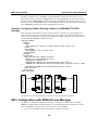
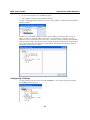
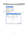
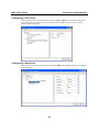
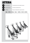
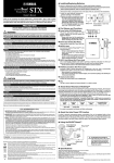
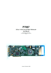
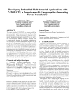
MOXA Protocol Converter Configuration and Programming Guide First Edition, May 2007 www.moxa.com/product MOXA Systems Co., Ltd. Tel: +886-2-2910-1230 Fax: +886-2-2910-1231 Web: www.moxa.com MOXA Technical Support [email protected] Worldwide: MOXA Protocol Converter Configuration and Programming Guide The software described in this manual is furnished under a license agreement and may be used only in accordance with the terms of that agreement. Copyright Notice Copyright © 2007 Moxa Systems Co., Ltd. All rights reserved. Reproduction without permission is prohibited. Trademarks MOXA is a registered trademark of The Moxa Group. All other trademarks or registered marks in this manual belong to their respective manufacturers. Disclaimer Information in this document is subject to change without notice and does not represent a commitment on the part of MOXA. MOXA provides this document “as is,” without warranty of any kind, either expressed or implied, including, but not limited to, its particular purpose. MOXA reserves the right to make improvements and/or changes to this manual, or to the products and/or the programs described in this manual, at any time. Information provided in this manual is intended to be accurate and reliable. However, MOXA assumes no responsibility for its use, or for any infringements on the rights of third parties that may result from its use. This product might include unintentional technical or typographical errors. Changes are periodically made to the information herein to correct such errors, and these changes are incorporated into new editions of the publication. Table of Contents Chapter 1 Introduction and Installation.......................................................................1-1 Field Applications .................................................................................................................... 1-1 MPC Software Architecture ..................................................................................................... 1-2 Installing MPC on a Linux Computer...................................................................................... 1-3 Installing MPC on a WinCE Computer.................................................................................... 1-3 Chapter 2 Configuration................................................................................................2-1 Editing a Configuration File .................................................................................................... 2-1 Configuring a TCP Server........................................................................................................ 2-2 Configuring a TCP Client ........................................................................................................ 2-2 Configuring a Serial Port ......................................................................................................... 2-3 Configuring a Channel............................................................................................................. 2-3 Configuring a Driver................................................................................................................ 2-4 Example: Configuring a MODBUS TCP/RTU Gateway......................................................... 2-4 Example: Configuring a MODBUS TCP/ASCII Gateway ...................................................... 2-5 Example: Configuring a Meter-Reading Channel on a MODBUS TCP/RTU Gateway .......... 2-6 MPC Configuration with MOXA Device Manager ................................................................. 2-6 Configuring a Channel............................................................................................................. 2-7 Configuring a TCP Server........................................................................................................ 2-8 Configuring a TCP Client ........................................................................................................ 2-9 Configuring a Serial Port ......................................................................................................... 2-9 Configuring a Driver.............................................................................................................. 2-10 Deleting a Channel................................................................................................................. 2-10 Chapter 3 MPC Driver Programming .......................................................................... A-1 x_driver.h File......................................................................................................................... A-1 Driver Functions ..................................................................................................................... A-2 Driver Example #1: MODBUS TCP....................................................................................... A-3 Driver Example #2: Timer Function ....................................................................................... A-5 Building a Linux MPC Driver ................................................................................................ A-6 Building a WinCE MPC Driver .............................................................................................. A-7 Appendix A Service Information..................................................................................... A-1 MOXA Internet Services......................................................................................................... A-2 Problem Report Form ............................................................................................................. A-3 Product Return Procedure ....................................................................................................... A-4 1 Chapter 1 Introduction and Installation MOXA Protocol Converter (referred to here as “MPC”) is a software program that runs on MOXA’s ready-to-run embedded computers. MPC is an engine that loads custom programs called drivers. The drivers audit bi-directional data streams between a network client and a serial device, or between two serial devices. The MPC engine implements a streamline architecture consisting of channels and drivers. A channel is a logical path connecting two physical communication ports (serial or network). A sequence of user-programmed drivers works in the middle to convert data from one protocol to another or handle data processing tasks. The engine receives a data stream at one communication port, assembles each data packet in the stream, and then passes the packets to the drivers for processing. Each driver performs data formatting or conversion on the packet, as required. The resulting packet is then passed to the next driver for further conversion. This process continues until the final packet reaches the physical port at the other end of the channel. One of the key benefits provided by MPC is that both serial and networking communication are built into the engine. Without any additional programming on the part of the user, the engine alone can perform transparent data transmission between any two communication ports (i.e., the data channel mentioned above). Another key benefit of MPC is that port-to-port communication is driver programmable. The engine supports multiple drivers in a channel, which simplifies and modularizes the design of an application that needs layers of data processing. In addition, most systems used in the field are created by making minor changes to existing systems. With the MPC engine, these changes can be achieved by either modifying a driver, or adding a driver to a channel. Field Applications Many industrial applications rely on a central system that monitors and controls a large number of devices distributed around the site. In this case, control commands are handled by Remote Terminal Units (RTUs) or Programmable Logic Controllers (PLCs), although many of the control commands are issued by a centralized host housed in an operations center. Communication between the different types of controllers can be carried out through a serial cable or over a LAN (local area network). Based on current practice, it is quite likely that embedded front-end computers will be installed at field sites to provide a kind of store-and-forward mechanism. The embedded computers get raw data, such as meter readings and device status reports, from the RTUs or PLCs, after which the data is compiled and/or formatted as needed. The resulting data is transmitted to the host in the operations room, and the operator generates control commands that are sent to the RTUs and PLCs. MPC User’s Guide Introduction and Installation The following figure indicates the general relationship between the host level, gateway level, and device level. Host Level MODBUS RTU MODBUS TCP Gateway Level MODBUS RTU MODBUS ASCII MODBUS ASCII Device Level MOXA’s embedded computers act at the gateway level to acquire information from serial devices and then report to the operators in the control room. The gateway can be used to send control signals to devices through the serial links, and provide access by multiple clients over the local network. The gateway can also be used to convert bi-directional data streams between serial devices. The gateways are used to allow serial and networking devices to communicate with each other. Since a poorly designed system could require engineers to implement the same task over and over again, there is a lot of motivation to find ways to streamline operations by reducing, or eliminating altogether, the number of duplicate tasks that must be performed. MPC comes to the rescue in this regard by consolidating common device communication tasks into a software engine, leaving the task of developing drivers for various types of data conversion to programmers who are experts in using the data formats and transmission protocols supported by the devices. MPC Software Architecture The MPC engine manages several communication channels, each of which has two communication ports that convert data streams. The ports can be either serial or network ports, and data received at one port will eventually be forwarded to the other port. The following figure shows an MPC channel linking two communication ports: port A (LAN) and port B (serial). The channel processes data packets in a pair of data streams: an up-stream and a down-stream. As shown, the receiving port of a data stream is also the sending port of another stream. Drivers (represented by dotted boxes in the figure) are arranged sequentially in the channel, and work to format the data packets. 1-2 MPC User’s Guide Introduction and Installation up-stream SERIAL LAN down-stream Let’s look at the up-stream part of the streamline to illustrate how the process works. After detecting the arrival of a data packet at port A, the channel passes it to the first driver for data processing. After formatting the packet, the driver forwards the resulting data to the second driver. The process proceeds in this way until the packet arrives at port B. Each driver is comprised of up to two user-defined logic functions, with each of the two functions commanding data conversion for one side of the data stream. For example, in a MODBUS TCP/RTU gateway, one function extracts and formats a TCP packet into an RTU packet for the up-stream, and another function extracts and formats an RTU packet into a TCP packet for the down-stream. The MPC engine also allows two communication ports of the channel to be of the same type. One example is a networking channel in which the receiving port is the same as the sending port. Incoming data packets are sent back to the sender either with no formatting, or after being formatted. Another example is a serial channel that has two different communication ports. Data from a serial port will be relayed to another serial port, again either with no formatting, or after being formatted. Installing MPC on a Linux Computer MPC is a user-space program called mpc. To install the program, first create a working directory in which the program will be stored. For example, you could create a working directory called /home/mpc. Next, use an ftp client to copy the program to this directory. Before executing the program, be sure to change the file mode so that the program will be executable in your system. Use the following command to modify the file mode. > chmod +x mpc Installing MPC on a WinCE Computer MPC is a user-space program called mpc.exe. To install the program, first create a working directory. For example, you could create a working directly called /NORFlash/mpc. Next, use an ftp client to copy the program to this directory. 1-3 2 Chapter 2 Configuration The channels and drivers can be arranged easily by editing a configuration file, or by using a utility that edits the configuration file for you. Before we describe the configuration file in detail, let’s look at the command used to invoke the MPC engine. The general format of the command is: mpc [-c config_path] Use the “-c” option to specify a configuration file, in which “config_path” is the full path of the configuration file. If you run “mpc” without specifying a configuration file, the mpc engine will assume that the configuration is in the file “config.mpc” in the root directory. Editing a Configuration File The configuration file is written in XML format, and consists of entries in text lines. The text is NOT case sensitive. The following simple configuration example illustrates some of the features of the protocol converter. <MPC_DOC_ROOT> <XPORTS> <UART> <MPC_PORT port=“1” baud_rate=“115200” data_bits=“8” parity=“None” stop_bits=“1” interface=“RS232” flow_control=“None” /> <MPC_PORT port=“8” baud_rate=“115200” data_bits=“8” parity=“None” stop_bits=“1” interface=“RS232” flow_control=“None” /> </UART> <TCP_SERVER> <MPC_PORT port=“5001” max_connections=“8” accepted_ips=““ rt_timeout=“200” /> <MPC_PORT port=“6001” max_connections=“10” accepted_ips=““ broadcast=“yes” /> </TCP_SERVER> </XPORTS> <XCHANNELS> <MPC_CHANNEL name=“CH1”> <PORT_A type=“TCP_SERVER” port=“5001” /> <PORT_B type=“UART” port=“1” /> <DRIVER name=“D1” dll=“/home/mpc/mbtcp.dll” prefix=“mbtcp” /> </MPC_CHANNEL> <MPC_CHANNEL name=“CH8”> <PORT_A type=“TCP_SERVER” port=“6001” /> <PORT_B type=“UART” port=“8” /> </MPC_CHANNEL> </XCHANNELS> </MPC_DOC_ROOT> The entire file is enclosed by a document root, <MPC_DOC_ROOT></MPC_DOC_ROOT>. There are two major sections that are enclosed by element pairs <XPORTS></XPORTS> and <XCHANNELS></XCHANNELS>, respectively. The first pair defines communication ports of different types. The second pair defines channels that are associated with the communication ports. MPC User’s Guide Introduction and Installation Configuring a TCP Server The <TCP_SERVER> section within the element pair <XPORTS></XPORTS> is used to specify the TCP servers that will accept client connections. Each of the server’s communication ports is characterized by the <MPC_PORT> element, in which several other attributes further describe the properties of the communication port: <MPC_PORT port=“5001” max_connections=“8” accepted_ips=““ rt_timeout=“200” broadcast=“yes” /> Attribute port Default N/A max_connections 4 accepted_ips N/A rt_timeout 200 Description Specifies the listening port of the server. This attribute must be defined, and its value must be great than 384. Limits the number of concurrent clients that the server will accept. The default value (4) will be used if this attribute is left open. This option is used to grant access right to privileged clients, which are identified by their IP addresses. If this attribute is not defined, then any client will be granted access. Setting the attribute to 172.16.2.0 will cause the MPC engine to accept clients with IP addresses ranging from 172.16.2.0 to 172.16.2.255. For multiple settings of this type, the IP addresses should be separated by spaces. The MPC engine does not split threads, but it tends to serve concurrent clients fairly. For this reason, the engine will not block transmissions while waiting for a response after sending a request to a slow serial device that is a shared resource. If the engine receives requests to the same serial device from more than one client, the requests are placed in a queue. While serving one request, the other requests in the queue are blocked temporarily. In some cases, a serial device may not respond to a request. In this case, blocked requests waiting for service will not be served. To avoid this kind of deadlock, the engine triggers a timer (measured in milliseconds) specified by rt_timeout for each request. If the timer expires before the engine gets a response, the blocked requests will be unblocked. broadcast no The choice of a proper value for this timer depends on the number of concurrent clients, the loading of the computer, the baud rate of the serial port, etc. If you do not need a timer, then don’t define this attribute. Setting this attribute to yes will allow clients connected to the same TCP server to share a response, regardless of which client issued the request. For example, set the attribute to yes if one client issues the control commands, and other clients simply need to view the response. Configuring a TCP Client The <TCP_CLIENT> part of the configuration file is used to specify multiple TCP clients, each of which is defined in the element <MPC_PORT>: 2-2 MPC User’s Guide Introduction and Installation <MPC_PORT port=“192.168.3.65:7001” rt_timeout=“200” /> Attribute port Default NA rt_timeout 200 Description Given a host name and a port number with ‘:’ in between, the MPC engine creates a TCP connection to the server at startup. Works exactly the same as the one defined for a TCP server. Configuring a Serial Port The <UART> part of the configuration file is used to list the serial ports, which are defined in element <MPC_PORT>. <MPC_PORT port=“1” baud_rate=“115200” data_bits=“8” parity=“None” stop_bits=“1” interface=“RS232” flow_control=“None” timeout=“50” /> Attribute port baud_rate Default N/A 9600 data_bits stop_bits parity 8 1 None interface RS322 flow_control no timeout 0 Description The port number (1, 2, …, 8) of the serial port. The baud_rate attribute can be set to any value from 50 to 921600. The data_bits attribute must be set to 5, 6, 7, or 8. The stop_bit attribute must be set to 1 or 2. The parity attribute should be set to either None, Odd, Even, Mark, or Space. The interface attribute can be set to RS322, RS422, RS485-2WIRE, or RS485-4WIRE. To avoid overflow on the serial port during data communication, enable flow control through the port by setting the flow_control attribute to Hardware or Software. We recommend using Hardware flow control. Data received from a serial port may be part of a data frame that will be processed by an application. To insure that the application processes the correct data, you can assign a value (measured in milliseconds) to the timeout attribute. After receiving the first piece of data in a frame from the serial port, a timer keeps track of the time (in milliseconds). Data received from the serial port before the timeout value is reached will be appended to the data frame. Once the timer reaches the timeout value, the data frame will be sent to the appropriate channel. Configuring a Channel The second major section of the configuration file enclosed by the element <XCHANNELS> pair is a section for defining channels. Each channel is defined within an <MPC_CHANNEL> pair, and has a name attribute, which can be used to provide a short description of the channel. <MPC_CHANNEL name=“CH1”> Elements PORT_A and PORT_B are used to specify two communication ports of the channel. These ports must be pre-defined in the <XPORTS></XPORTS> section. Element PORT_B can be left open if the channel forms a loop path starting from a communication port and ending at the same port. 2-3 MPC User’s Guide Introduction and Installation <PORT_A type=“TCP_SERVER” port=“5001” /> <PORT_B type=“UART” port=“1” /> Attribute type port Description The type attribute should be set to TCP_SERVER, TCP_CLIENT or UART. Set the “port” attribute to the port number of the communication port, which must be defined already in the <XPORTS></XPORT> section. Configuring a Driver The <DRIVER> element uses the alias “name” to define a driver in the channel. <DRIVER name=“D1” dll=“/home/mpc/mbtcp.dll” prefix=“mbtcp” time_interval=“2000” /> Attribute name dll prefix time_interval Description Use the “name” attribute to give a short description of the driver. Specify the full path of the driver object or the dynamic library. The prefix is a short string used as a prefix in the name of the driver functions that the MPC engine will call. For example, the prefix mbtcp could be used in the names of functions implemented by the driver. Examples of possible function names are mbtcp_open, mbtcp_close, mbtcp_exec_A2B, mbtcp_exec_B2A, and mbtcp_exec_timer. The time_interval attribute, which is measured in milliseconds, should be defined if you implement a timer function (e.g, mbtcp_exec_timer) that the engine calls periodically. This timer is particularly useful when an application needs to issue a request to a serial port periodically. However, please note that every timer uses CPU resources, so do not use a timer unless you really need it. Example: Configuring a MODBUS TCP/RTU Gateway Modbus is a standard serial communication protocol used in field devices, such as programmable logic controllers (PLCS) and remote terminal units (RTUs). Modbus is most commonly used to connect a host computer to industrial electronic devices in SCADA (Supervisory Control And Data Acquisition) systems. We provide the source code required to enable an MPC channel as a Modbu TCP/RTU/ASCII gateway. Source code is available for shared objects in Linux, or dynamic-link libraries in WinCE. You can search the software package we provide to locate the source code you need. If the source code is not appropriate for your application, you can always modify the code and then recompile it. Here is an example: <MPC_DOC_ROOT> <XPORTS> <UART> <MPC_PORT port=“1” baud_rate=“115200” interface=“RS485” timeout=“50” /> </UART> <TCP_SERVER> <MPC_PORT port=“502” rt_timeout=“200” /> </TCP_SERVER> </XPORTS> <XCHANNELS> <MPC_CHANNEL name=“Modbus_TCP_RTU”> <PORT_A type=“TCP_SERVER” port=“502” /> <PORT_B type=“UART” port=“1” /> 2-4 MPC User’s Guide Introduction and Installation <DRIVER name=“MBTCP” dll=“/home/mpc/mbtcp.dll” prefix=“mbtcp” /> <DRIVER name=“MBRTU” dll=“/home/mpc/mbrtu.dll” prefix=“mbrtu” /> </MPC_CHANNEL> </XCHANNELS> </MPC_DOC_ROOT> mbrtu.dll SERIAL PORT #1 TCP SERVER 502 mbtcp.dll The above example sets up a MODBUS TCP/RTU/RS485 channel between TCP server port 502 and serial port #1. The driver mbtcp.dll converts each MODBUS/TCP packet into raw data, and then the driver mbrtu.dll assembles the data into a MODBUS/RTU packet. In the reverse direction, the driver mbrtu.dll converts each MODBUS/RTU packet into raw data and then the driver mbtcp.dll assembles the data into a MODBUS/TCP packet. Example: Configuring a MODBUS TCP/ASCII Gateway <MPC_DOC_ROOT> <XPORTS> <UART> <MPC_PORT port=“2” baud_rate=“115200” interface=“RS485” timeout=“50” /> </UART> <TCP_SERVER> <MPC_PORT port=“5001” rt_timeout=“200” /> </TCP_SERVER> </XPORTS> <XCHANNELS> <MPC_CHANNEL name=“Modbus_TCP_ASCII”> <PORT_A type=“TCP_SERVER” port=“5001” /> <PORT_B type=“UART” port=“2” /> <DRIVER name=“MBTCP” dll=“/home/mpc/mbtcp.dll” prefix=“mbtcp” /> <DRIVER name=“MBASCII” dll=“/home/mpc/mbrtu.dll” prefix=“mbascii” /> </MPC_CHANNEL> </XCHANNELS> </MPC_DOC_ROOT> mbascii.dll 2-5 SERIAL PORT #2 TCP SERVER 5001 mbtcp.dll MPC User’s Guide Introduction and Installation The above example sets up a MODBUS TCP/ASCII/RS485 channel between TCP server port 5001 and serial port #2. The driver mbtcp.dll converts each MODBUS/TCP packet into raw data and then the driver mbascii.dll assembles the data into a MODBUS/ ASCII packet. In the reverse direction, the driver mbascii.dll converts each MODBUS/ ASCII packet into raw data and then the driver mbtcp.dll assembles the data into a MODBUS/TCP packet. Example: Configuring a Meter-Reading Channel on a MODBUS TCP/RTU Gateway Most applications need timers to trigger periodic requests to field devices to get readings and report to the host center. For example, a meter application needs to query device readings every 5 seconds. One can implement a timer function, meter_exec_timer, inside the driver meter.dll and set attribute timer_interval to 5000 milliseconds. <MPC_DOC_ROOT> <XPORTS> <UART> <MPC_PORT port=“1” baud_rate=“115200” interface=“RS485” timeout=“50” /> </UART> <TCP_SERVER> <MPC_PORT port=“502” rt_timeout=“200” /> </TCP_SERVER> </XPORTS> <XCHANNELS> <MPC_CHANNEL name=“Modbus_TCP_RTU”> <PORT_A type=“TCP_SERVER” port=“502” /> <PORT_B type=“UART” port=“1” /> <DRIVER name=“MBTCP” dll=“/home/mpc/mbtcp.dll” prefix=“mbtcp” /> <DRIVER name=“METER” dll=“/home/mpc/meter.dll” prefix=“ meter”timer_interval = “5000” /> <DRIVER name=“MBRTU” dll=“/home/mpc/mbrtu.dll” prefix=“mbrtu” /> </MPC_CHANNEL> </XCHANNELS> </MPC_DOC_ROOT> meter.dll mbrtu.dll SERIAL PORT #1 TCP SERVER 502 mbtcp.dll The driver meter.dll is inserted between the driver mbtcp.dll and driver mbrtu.dll. MPC Configuration with MOXA Device Manager In addition to editing the configuration manually, you can also use MOXA Device Manager (MDM) to configure MPC channels and drivers. For detailed information about this tool, please refer to the MDM user guide. Follow the steps below to activateMDM: 1. Log on to the embedded computer and start the MDMAgent program. 2-6 MPC User’s Guide Introduction and Installation 2. On your own computer, start the MDM program. 3. Start the MPC program on the embedded computer. To begin configuring channels and drivers, locate “Group of MPC” in the left panel of the Device Manager window. IP addresses of embedded computers currently running MPC will be listed under “Group of MPC.” Double click on the IP address of the device you would like to configure to invoke a Windows version of “MOXA Protocol Converter.” Channels currently running in the embedded computer will be listed in the left panel of the window. Information related to the communication ports will be listed under each channel. The information includes their types and port numbers. The number of drivers is also shown. Configuring a Channel To add a channel, right click on the root node, Channels, or on a channel node itself, and then select Add from the pop-up list. 2-7 MPC User’s Guide Introduction and Installation When the Add a Channel window opens, input a channel name and select the type of communication ports you would like to assign to Port A and Port B. Click OK to confirm the settings. Configuring a TCP Server A new channel node will appear in the left panel. Under the node, click the TCP_SERVER child node and then configure the TCP server in the right panel. 2-8 MPC User’s Guide Introduction and Installation Configuring a TCP Client In the left panel associated with a channel, click the TCP_CLIENT node and then configure the TCP client in the right panel. You will need to input the IP address of the server host and the corresponding listening port. Configuring a Serial Port In the left panel associated with a channel, click the UART node and then configure the serial port in the right panel. 2-9 MPC User’s Guide Introduction and Installation Configuring a Driver To add a driver in a channel, click on the Drivers child node. In the right panel, input the name, the full path of the shared object, and the driver’s prefix string. Deleting a Channel To delete a channel, right click on the channel and select Delete. After completing the configuration, click the Apply To Device button in the bottom right corner of the main panel to save the configuration to the device. Clicking this button will also trigger the MPC engine to reload the new configuration. 2-10 MPC User’s Guide Introduction and Installation When a channel with drivers is enabled, the MPC engine tracks data flow (in bytes) for each driver. To obtain the data flow information, right click on the Drivers child node and then select Refresh. To refresh the configuration, right click on the root node Channels and then select Refresh. To shut down the MPC engine, select Shutdown from the root node. 2-11 3 Chapter 3 MPC Driver Programming We assume that you have installed either a Linux tool chain or Microsoft eVC++ 4.0 on your development workstation. Linux drivers are in the format of executable shared objects, and WinCE drivers are in the format of dynamic-link libraries. Note that the MPC engine does not support computers that use the µcLinux operating system. This is because µcLinux does not support shared objects. The MPC engine is written in C, and for this reason, the drivers you create must also be written in C. After compiling the drivers, the resulting driver files will be in the form of shared objects or dynamic link libraries. Note that your drivers use the same memory context as the MPC engine. For this reason, it is your responsibility to use a “clean design” for your drivers. If your driver design is flawed, then code violations of your drivers could cause a core dump of the MPC engine. There is no need to use binary APIs when programming your drivers, but developers need to follow the correct function definitions for a given x_driver.h file. Developers can make a copy of this file, and then save it in a location accessible by your program. x_driver.h File This file regulates the relative data addresses used in the engine and your drivers. It must be included when you compile your codes. #ifndef _X_DRV_H #define _X_DRV_H #define MPC_DRV_OK #define MPC_DRV_FAIL 0 0xffffffff typedef struct _DRVRPKT { char *port; /* specify the port # defined in the configuration file */ unsigned int hndl; /* the handle of a client connection, may be NULL */ char* packet_data; /* data to be consumed and forwarded */ int packet_size; /* bytes in packet_data */ int packet_consumed; /* bytes consumed in packet_data after the execution of a driver function*/ } DRVRPKT; typedef void (*xxx_driver_timer) (void *private_data, DRVRPKT *pktA, DRVRPKT *pktB, unsigned int *timer_interval); typedef int (*xxx_driver_exec) (void *private_data, DRVRPKT *pktX); typedef void* (*xxx_driver_open) (char *portA, char *portB, int *rtn); typedef void (*xxx_driver_close) (void *private_data); #endif Service Information MPC User’s Manual The structure DRVRPKT is an interface between the MPC engine and driver functions. Before calling a driver function, the engine prepares a data structure that describes the content and the size of a data packet. The function processes the data packet, and describes the content/size of the resulting data in the same data structure before ending the call. Field Members [in] port Specifies the communication port as that defined in the configuration file. [in] hndl Specifies the connection handle of the communication port from which the data packet comes. It can be NULL in a timer function. [in/out] packet_data Specifies the memory area for storing the original data packet that is received by the engine and passed to a driver function. Before handing process control back to the engine, the driver function must assign another malloc or static area that stores the resulting data packet. [in/out] packet_size Specifies the size of the data packet that packet_data initially points to. Before ending its call, a driver function must specify it to be the size of the resulting data. Setting the value to zero means it will stop forwarding the data packet to another driver. [in/out] packet_consumed A driver function must specify the number of bytes that are consumed in the original packet. With this information, the engine is informed to remove the data to be processed. This value is initially equal to the number of bytes of the original data packet. Driver Functions A driver is composed of driver functions prefixed by a string (xxx, for example). The functions are called when the associated channel is established. For example, the definition of a function xxx_open would look like this: void* xxx_open(char *portA, char *portB, int *rtn); The string-type arguments portA and portB represent the two ports that make up the ends of the channel. The function normally returns the address of allocated memory space that will be referenced when the following functions are executed. A NULL value can be returned if the reference is of no importance. The closing function of the driver is implemented when the channel is released. void xxx_close(void *private_data); Normally, this function frees up the allocated memory pointed to by private_data. Three execution functions are called by the MPC engine: xxx_exec_A2B, xxx_exec_B2A, and xxx_exec_timer. At least one of the functions must be implemented. The function xxx_exec_A2B is called each time a data packet is passed from port A to this driver. In contrast, the function xxx_exec_B2A handles data packets in the reverse direction. Use the following formats to implement these functions: int xxx_exec_A2B(void *private_data, DRVRPKT *pktX); int xxx_exec_B2A(void *private_data, DRVRPKT *pktX); Before the function is called, the engine prepares the structure body DRVRPKT pointed to by the argument pktX. Member packet_data points to the data packet, and member packet_size is the A-2 Service Information MPC User’s Manual length of the data packet. In addition, member packet_consumed has the same value as member packet_size. This implies that the engine assumes that the function consumes the whole packet. After processing the data, the function is responsible for pointing member packet_data to the memory area (normally private_data) that stores the resulting data, and specify the length of it in member packet_size. If the function decides not to forward data to the next driver, it sets packet_size to zero. Furthermore, this function must specify member packet_consumed to be the length of the data being consumed, and informs the engine is to remove the processed data. This function returns one of the following symbolic constants: y MPC_DRV_OK – indicates that the driver has processed data successfully. y MPC_DRV_FAIL –indicates that the driver has stopped forwarding the data packet Each driver has the option to implement a timer function periodically. The function is called by the MPC engine. The time interval between each call is in milliseconds, and must be defined in the configuration file. The main role of this function is normally to generate a data query, and asks the engine to relay the data to the next driver or a target port. void xxx_exec_timer(void *private_data, DRVRPKT *pktA, DRVRPKT *pktB, unsigned int *timer_interval); When the timer function is called, all structure members in pktA and pktB are set to zeros. The function uses member packet_data and packet_size of pktA to forward data to port A, and members packet_data and packet_size of pktB to forward data to port B. Other members are ignored. Before ending the call, the function can also change the timer interval of the timer by specifying the argument timer_interval. Driver Example #1: MODBUS TCP In this section, we present an example of a MODBUS/TCP driver was described in the previous chapter when we configured a MODBUS gateway. The purpose of providing this example is to help you understand the idea of how to implement an MPC driver. For features other than what it can provide, you can modify it to fit your needs. #include “modbus_tcp.h” #ifdef _WIN32_WCE BOOL APIENTRY DllMain( HANDLE hModule, DWORD ul_reason_for_call, LPVOID lpReserved ) { return TRUE; } #endif /* convert a TCP frame <trans_identifier:2><proto_identifier:2><length:2><data> to <data> */ int mbtcp_exec_A2B(void *private_data, DRVRPKT *pkt) { MBTCPFRM *mb = (MBTCPFRM*) private_data; int length, consumed = pkt->packet_size; dbgprint(“mbtcp_exec_A2B: pkt->packet_size %d mb 0X%X \n”, pkt->packet_size, mb); A-3 Service Information MPC User’s Manual /* obtain a TCP frame */ length = modbus_digest_tcp(pkt->packet_data, &consumed, mb); if (length > 0) { pkt->packet_data = &mb->slave_address; pkt->packet_consumed = consumed; pkt->packet_size = (unsigned int) length; dbgprint(“mbtcp_exec_A2B: packet_data 0X%X length %d\n”, pkt->packet_data, length); } else { pkt->packet_consumed = 0; pkt->packet_size = 0; dbgprint(“mbtcp_exec_A2B: WARNNING:**** length %d\n”,length); } dbgprint(“mbtcp_exec_A2B: port (%s) consumed (%d) pass (%d) bytes\n”, pkt->port, pkt->packet_consumed, pkt->packet_size); return MPC_DRV_OK; } /* format a TCP frame <data> to <trans_identifier:2><proto_identifier:2><length:2><data> */ int mbtcp_exec_B2A(void *private_data, DRVRPKT *pkt) { MBTCPFRM *mb = (MBTCPFRM*) private_data; int length, consumed = pkt->packet_size; length = modbus_format_tcp(pkt->packet_data, pkt->packet_size, mb); if (length > 0) { pkt->packet_consumed = consumed; pkt->packet_size = (unsigned int) length; dbgprint(“mbtcp_exec_B2A: packet_data 0X%X length %d\n”, pkt->packet_data, length); } else { pkt->packet_consumed = 0; pkt->packet_size = 0; dbgprint(“mbtcp_exec_B2A: ERROR:****\n”); } pkt->packet_data = (unsigned char*) mb; dbgprint(“mbtcp_exec_B2A: port (%s) consumed (%d) pass (%d) bytes\n”, pkt->port, pkt->packet_consumed, pkt->packet_size); return MPC_DRV_OK; } /* free up memory while closing the driver */ int mbtcp_close(void *private_data) { dbgprint(“mbtcp_close\n”); if (private_data) free(private_data); return MPC_DRV_OK; } A-4 Service Information MPC User’s Manual /* return a private buffer */ void* mbtcp_open(char *portA, char *portB, int *rtn) { MBTCPFRM *mb = (MBTCPFRM*) calloc(1, sizeof(MBTCPFRM)); dbgprint(“mbtcp_open (%s to %s)\n”, portA, portB); *rtn = (!mb)? MPC_DRV_FAIL:MPC_DRV_OK; return mb; } This driver implements four driver functions: mbtcp_open, mbtcp_close, mbtcp_exec_A2B, and mbtcp_exec_B2A. The opening function allocates a memory area for storing a MODBUS TCP data frame. The closing function frees up the allocated memory. In functions mbtcp_exec_A2B and mbtcp_exec_B2A, this driver calls internal functions modbus_digest_tcp and modbus_format_tcp to digest and assemble MODBUS TCP packets, respectively. The two internal functions can be found in the file modbus_tcp.c. Driver Example #2: Timer Function A MODBUS TCP/RTU application may need a timer function to issue periodic requests to the serial device. The following example, e5cn_exec_timer, assigns the slave address, function code, and addresses associated with the request. In addition, it simply indicates 6 bytes of the data to be forwarded. #include <stdlib.h> #include <stdio.h> #include <string.h> #include “../x_driver.h” #ifdef _WIN32_WCE #include “../stdafx.h” BOOL APIENTRY DllMain( HANDLE hModule, DWORD ul_reason_for_call, LPVOID lpReserved ) { return TRUE; } #endif int e5cn_exec_timer(void *private_data, DRVRPKT *pktA, DRVRPKT *pktB, unsigned int *timer_interval) { unsigned char *buffer = (unsigned char *) private_data; buffer[0] = 0x01; buffer[1] = 0x03; /* read data */ buffer[2] = 0x00; /* read start address HI */ buffer[3] = 0x00; /* read start address LO */ buffer[4] = 0x00; /* # of elements HI */ buffer[5] = 0x01; /* # of elements LO */ pktB->packet_size = 6; pktB->packet_data = buffer; printf(“e5cn_exec_timer size %d timer_interval %d\n”, pktB->packet_size, *timer_interval); A-5 Service Information MPC User’s Manual return MPC_DRV_OK; } /* free up memory while closing the driver */ int e5cn_close(void *private_data) { printf(“++e5cn_close\n”); if (private_data) free(private_data); return MPC_DRV_OK; } /* return a private buffer */ void* e5cn_open(char *portA, char *portB, int *rtn) { unsigned char *buffer = (unsigned char*) calloc(1, 512); printf(“e5cn_open (%s to %s)\n”, portA, portB); *rtn = (!buffer)? MPC_DRV_FAIL:MPC_DRV_OK; return buffer; } Building a Linux MPC Driver Before building a Linux driver, you need to create a Makefile. For example, the following Makefile would be used with the UC-7420-LX. CC=mxscaleb-gcc STRIP=mxscaleb-strip -s AR=mxscaleb-ar rcs EXEC=dxxx.dll CFLAGS=-Wall -fPIC LINK=$(CC) -shared -Wl,-soname,$(EXEC) -o $@ LIBS= # add objects OBJS= dxxx.o DEPS= all: $(EXEC) $(EXEC): $(OBJS) $(DEPS) $(LINK) $(OBJS) $(LIBS) clean: rm -f *.o $(EXEC) Compile the shared object, dxxx.dll, for the driver. > make A-6 Service Information MPC User’s Manual Building a WinCE MPC Driver The following steps show you how to generate a project, and program a driver with Microsoft eVC++ 4.0. 1. Open the eVC++ 4.0 program. On the menu bar, click File and New… to create a new project. 2. In the pop-up window, select WCE Dynamic-Link Library. Enter a project name and then click OK. 3. Select An empty Windows CE DLL project, and then click Finish. A-7 Service Information MPC User’s Manual 4. Click OK to complete the project creation. 5. On the eVC++ 4.0 menu bar, click Project Æ Add to Project Æ Files to add source files to the project. Remember to add an empty file, dxxx.def. 6. Edit the source files. A-8 Service Information MPC User’s Manual 7. Edit the file dxxx.def. Behind the keyword LIBRARY in the first line, specify the name of the dll. dxxx for example. Add the keyword EXPORTS in the second line, and then add the function names of the driver, as shown below. 8. Press the F7 key to compile the driver. A-9 A Appendix A Service Information This appendix shows you how to contact MOXA for information about this and other products, and how to report problems. The following topics are covered in this appendix. MOXA Internet Services Problem Report Form Product Return Procedure Service Information MPC User’s Manual MOXA Internet Services Customer satisfaction is our primary concern. To ensure that customers receive the full benefit of our products, MOXA Internet Services has been set up to provide technical support, driver updates, product information, and user’s manual updates. The following services are provided E-mail for technical support .......................................mailto:[email protected] Widesite for product information ...............................http://www.moxa.com A-2 Service Information MPC User’s Manual Problem Report Form MOXA Embedded Computer Series Customer name: Company: Tel: Fax: Email: Date: 1. Moxa Product: _________________ 2. Serial Number: _________________ Problem Description: Please describe the symptoms of the problem as clearly as possible, including any error messages you see. A clearly written description of the problem will allow us to reproduce the symptoms, and expedite the repair of your product. A-3 Service Information MPC User’s Manual Product Return Procedure For product repair, exchange, or refund, the customer must: Provide evidence of original purchase. Obtain a Product Return Agreement (PRA) from the sales representative or dealer. Fill out the Problem Report Form (PRF). Include as much detail as possible for a shorter product repair time. Carefully pack the product in an anti-static package, and send it, pre-paid, to the dealer. The PRA should be visible on the outside of the package, and include a description of the problem, along with the return address and telephone number of a technical contact. A-4