1
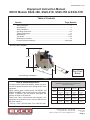
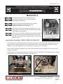
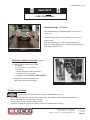
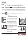
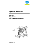
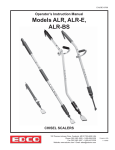
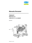
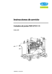
E-SS2636-DGE-I-1012 Operator’s Instruction Manual SS-26, SS-36 & SS-26E SS-26 Shown Self-Propelled Concrete/Asphalt Saw Diesel, Gasoline & Electric available 100 Thomas Johnson Drive, Frederick, MD 21702-4600 USA Phone (301) 663-1600 • 1-800-638-3326 Fax (301) 663-1607 • 1-800-447-3326 Website: www.edcoinc.com • Email: [email protected] Printed in USA TVW ©2012 Page 1 E-SS2636-DGE-I-1012 READ AND UNDERSTAND THE OPERATORS INSTRUCTION MANUAL THOROUGHLY BEFORE ATTEMPTING TO OPERATE THIS EQUIPMENT. Death or serious injury could occur if this machine is used improperly. SAFETY SAFETY MESSAGES MESSAGES • Safety Instructions are proceeded by a graphic alert symbol of DANGER, WARNING, or CAUTION. Indicates an imminent hazard which, if not avoided, will result in death or serious injury. Indicates an imminent hazard which, if not avoided, can result in death or serious injury. Indicates hazards which, if not avoided, could result in serious injury and or damage to the equipment. GASOLINE/PROPANE POWERED EQUIPMENT • Engine exhaust from this product contains chemicals known to the State of California to cause cancer, birth defects or other reproductive harm. • Gasoline is extremely flammable and poisonous. It should only be dispensed in well ventilated areas, and with a cool engine. • Small gasoline engines produce high concentrations of carbon monoxide (CO) example: a 5 HP 4 cycle engine operation in an enclosed 100,000 cu. ft. area with only one change of air per hour is capable of providing deadly concentrations of CO in less than fifteen minutes. Five changes of air in the same area will produce noxious fumes in less than 30 minutes. Gasoline or propane powered equipment should not be used in enclosed or partially enclosed areas. Symptoms of CO poisoning include, headache, nausea, weakness, dizziness, visual problems and loss of consciousness. If symptoms occur - get into fresh air and seek medical attention immediately. ELECTRICAL POWERED EQUIPMENT • • • • Extreme care must be taken when operating electric models with water present: Ensure power cord is properly grounded, is attached to a Ground-Fault-Interrupter (GFI) outlet, and is undamaged. Check all electrical cables - be sure connections are tight and cable is continuous and in good condition. Be sure cable is correctly rated for both the operating current and voltage of this equipment. Improper connection of the equipment-grounding conductor can result in a risk of electric shock. Check with qualified electrician or service person if there is any doubt as to whether the outlet is properly grounded. Adhere to all local codes and ordinances. NOTE: In the event of a malfunction or breakdown, grounding provides a path of least resistance for the electric current to dissipate. The motor is equipped with a grounded plug and must be connected to an outlet that is properly installed and properly grounded. DO NOT modify the plug provided on the motor. If the plug does not fit the outlet have a qualified electrician install the proper receptacle. Switch motor OFF before disconnecting power. Printed in USA ©2012 TVW Page 2 100 Thomas Johnson Drive, Frederick, MD 21702-4600 USA Phone (301) 663-1600 • 1-800-638-3326 Fax (301) 663-1607 • 1-800-447-3326 Website: www.edcoinc.com • Email: [email protected] • Do not disconnect power by pulling cord. To disconnect, grasp the plug, not the cord. • Unplug power cord at the machine when not in use and before servicing. GENERAL INSTRUCTIONS • Equipment should only be operated by trained personnel in good physical condition and mental health (not fatigued). The operator and maintenance personnel must be physically able to handle the bulk weight and power of this equipment. • This is a one person tool. Maintain a safe operating distance to other personnel. It is the operators’ responsibility to keep other people (workers, pedestrians, bystanders, etc.) away during operation. Block off the work area in all directions with roping, safety netting, etc. for a safe distance. Failure to do so may result in others being injured by flying debris or exposing them to harmful dust and noise. • This equipment is intended for commercial use only. • For the operator’s safety and the safety of others, always keep all guards in place during operation. • Never let equipment run unattended. • Personal Protection Equipment and proper safety attire must be worn when operating this machinery. The operator must wear approved safety equipment appropriate for the job such as hard hat and safety shoes when conditions require. Hearing protection MUST be used (operational noise levels of this equipment may exceed 90db). Eye protection MUST be worn at all times. Keep body parts and loose clothing away from moving parts. Failure to do so could result in dismemberment or death. • Do not modify the machine. • Stop motor/engine when adjusting or servicing this equipment. Maintain a safe operating distance from flammable materials. Sparks from the cutting-action of this machine can ignite flammable materials or vapors. DUST WARNING Some dust created by power sanding, sawing, grinding, drilling, and other construction activities contains chemicals known to cause cancer, birth defects, or other reproductive harm. Some examples of these chemicals are: • Lead from lead-based paints, and • Crystalline silica from bricks and concrete and other masonry products. Your risk of exposure to these chemicals varies depending on how often you do this type of work. To reduce your risk: work in a well ventilated area, use a dust control system, such as an industrial-style vacuum, and wear approved personal safety equipment, such as a dust/particle respirator designed to filter out microscopic particles. E-SS2636-DGE-I-1012 Equipment Instruction Manual EDCO Models SS26-38K, SS26-31D, SS26-15E & SS36-57D Table of Contents Section Page Number Safety Messages.........................................................................................................2 Specifications..............................................................................................................3 Safety Guidelines........................................................................................................4 Operating Instructions..............................................................................................5-9 Tracking Adjustment....................................................................................................9 Maintenance.........................................................................................................11-16 Your Notes............................................................................................................17-18 Maintenance Schedule..............................................................................................19 Limited Equipment Warranty..........................................................................back page SS-26-38K Shown Height See Chart Below Width Length Varies with type of bladeguard Figure 1 HOW TO ORDER REPAIR PARTS To insure product safety and reliability, always use genuine EDCO replacement parts when making repairs to the equipment. When ordering parts, please specify the MODEL and SERIAL NUMBER of the machine as given on the NAMEPLATE. In addition, give part number, description and quantity as listed on the parts list. Please note: Due to improvements and changes in the equipment the illustrations shown may be different from the actual machine. Specifications and dimensions are approximate and subject to change Model SS26-38K SS26-31D SS26-15E SS36-57D Height 50 1/2” 128.27cm 63” 160.02cm 50 1/2” 128.27cm 61” 154.94cm Width 32” 81.28cm 32” 81.28cm 32” 81.28cm 36” 91.44cm Length 58” 147.32cm 57 1/4” 145.41cm 58” 147.32cm 69” 175.26cm Weight 995 lbs 451kg 1225 lbs 556kg 1094 lbs 451kg 1588 lbs 720kg Toll Free: Voice 1-800-638-3326 • Fax 1-800-447-3326 100 Thomas Johnson Drive, Frederick, MD 21702-4600 USA Phone (301) 663-1600 • 1-800-638-3326 Fax (301) 663-1607 • 1-800-447-3326 Website: www.edcoinc.com • Email: [email protected] Printed in USA TVW ©2012 Page 3 E-SS2636-DGE-I-1012 Read and understand the Operator’s Instruction Manual, the Rx for Concrete Saws, and the Engine Manufacturer’s Owner’s Manual before operating this equipment. Death or serious injury can result if this machine is used improperly. Safety Guidelines Remove all rings, watches and jewelry prior to doing any work inside the console area. Metallic jewelry could short out the positive lead on the battery or the hydraulic power unit and cause severe bodily injury. Maintain a safe operating distance from flammable materials. Sparks from the cutting-action of this saw can ignite flammable materials or vapors. Operator must wear appropriate clothing and footwear. Do not wear loose clothing or jewelry that can get tangled or caught in moving parts. Eye and ear protection must be worn at all times when this machine is in use. During normal use, sound levels exceed 92dB. Use only ANSI approved safety glasses to help prevent eye injury. Normal, prescription eyeglasses have only impact resistant lenses; they are NOT safety glasses. • Keep a safe operating distance from other personnel and never leave the machine running unattended. • Maintain the machine in safe operating condition with all guards in place and secure, all mechanical fasteners tight, all controls in working order and the saw configured for the job application. • The SS26-38K, SS26-31D & SS36-57D are both designed to cut flat, horizontal concrete or asphalt slabs using diamond saw blades. • The SS26-38K, SS26-31D & SS36-57D are to be operated by a single operator from a position at the rear of the saw. • Avoid deck inserts, pipes, columns, openings, electrical outlets, or any objects protruding from slab surface. • Inspect the blades carefully before installing. Do not use any questionable blade since serious personal injury and/or damage to property can result. • Never operate this saw while under the influence of drugs, alcohol or when taking medications that impair the senses or reactions, or when excessively tired or under stress. • Be sure all safety decals on the machine can be clearly read and understood. Replace damaged or missing decals immediately. Safety warnings and guidelines do not by themselves eliminate danger. They are not given as substitutes for proper accident prevention and good judgement. Printed in USA ©2012 TVW Page 4 100 Thomas Johnson Drive, Frederick, MD 21702-4600 USA Phone (301) 663-1600 • 1-800-638-3326 Fax (301) 663-1607 • 1-800-447-3326 Website: www.edcoinc.com • Email: [email protected] E-SS2636-DGE-I-1012 SS26-38K Gasoline Powered Operating Controls 1 9 8 5 2 4 16 7 6 3 17 11 13 12 10 15 10 DC Hydaulic Power Unit mounted inside compartment at this location. (See page 10) 14 Figure 3 SS26-38K Operator’s Console 1. 2. 3. 4. 5. 6. 7. 8. 9. 10. 11. 12. 13. 14. 15. 16. 17. Ammeter Hour Meter Cut Control Depth Gauge Blade Saver Switch Water Pump Switch Ignition Switch Choke Throttle Handle Locks Clutch Drive Control Lever Blade Lift/Lower Rocker Switch Water Hook Up Gasoline Fill Cap Low Oil Indicator Emergency Stop NOTE: Due to design changes and advances in technology your machine may not look exactly like machines illustrated in this manual. All controls function in the same manner. 100 Thomas Johnson Drive, Frederick, MD 21702-4600 USA Phone (301) 663-1600 • 1-800-638-3326 Fax (301) 663-1607 • 1-800-447-3326 Website: www.edcoinc.com • Email: [email protected] Printed in USA TVW ©2012 Page 5 E-SS2636-DGE-I-1012 Diesel Powered Operating Controls 5 11 8 1 2 3 4 SS36-57D Operator’s Console 14 15 6 7 12 9 13 19 16 17 10 18 18 DC Hydaulic Power Unit mounted inside compartment at this location. (See page 11) (Figure 9) Figure 4 1. Oil Pressure Indicator 2. Oil Temperature Indicator 3. Alternator Failure Indicator 4. Glow Plug Indicator 5. Depth Control 6. Ignition Switch 7. Depth Indicator 8. Blade Saver Switch 9. Water Pump Switch 10. Free Wheeling Clutch 11. Tachometer / Hour Meter 12. Blade Lift / Lower Rocker Switch 13. Drive Control Lever 14. Guide Bar Rope 15. Throttle 16. Emergency Stop Button 17. Hydraulic Oil Fill 18. Handle Locks 19. Guide To Operation SS26-31D Operator’s Console 13 7 5 8 17 18 10 1 2 3 14 6 11 9 15 12 4 17 16 DC Hydaulic Power Unit mounted inside compartment at this location. (See page 11) (Figure 9) Figure 5 1. Oil Pressure Indicator 2. Oil Temperature Indicator 3. Alternator Failure Indicator 4. Depth Control 5. Ignition Switch 6. Depth Indicator 7. Blade Saver Switch 8. Water Pump Switch 9. Free Wheeling Clutch 10. Tachometer / Hour Meter 11. Blade Lift / Lower Rocker Switch 12. Drive Control Lever 13. Guide Bar Rope 14. Throttle 15. Emergency Stop Button 16. Hydraulic Oil Fill 17. Handle Locks 18. Guide To Operation NOTE: Due to design changes and advances in technology your machine may not look exactly like machines illustrated in this manual. All controls function in the same manner. Printed in USA ©2012 TVW Page 6 100 Thomas Johnson Drive, Frederick, MD 21702-4600 USA Phone (301) 663-1600 • 1-800-638-3326 Fax (301) 663-1607 • 1-800-447-3326 Website: www.edcoinc.com • Email: [email protected] E-SS2636-DGE-I-1012 Electric Powered Operating Controls SS26-15E Operator’s Console 76 5 9 1 2 3 4 12 8 7 11 15 13 16 10 16 14 Figure 5A DC Hydaulic Power Unit mounted inside compartment at this location. (See page 11) (Figure 9) 1. 2. 3. 4. 5. 6. 7. 8. 9. 10. 11. 12. 13 14. 15. 16. AMP Meter Hour Meter Water Pump Switch Depth Indicator OFF/E-STOP Button (RED) On Button (GREEN) Battery Saver Switch Low Water Pressure Alert Guide Bar Rope Blade Lift / Lower Rocker Switch Drive Control Lever Depth Control Hydraulic Oil Fill Free Wheeling Clutch Guide To Operation Handle Locks With the exception of the ON and OFF/E-STOP buttons the electric version of this saw and its controls operate the same as Gasoline and Diesel models described in this manual. Above are descriptions of all controls and indicators shown in Figure 5A. Service and maintenance are the same as Gasoline and Diesel models. CAUTION: Before attempting to start the saw be sure blade is not contacting the work surface or in a cut. If saw ever stops with blade in cut raise blade out of cut by putting item #11 in the neutral position first, then use item #10 to raise the blade. NOTE: When machine is not in use turn item #7 “Battery Saver Switch” OFF. If switch is left turned ON the battery will be drained over a period of time. Turn item #3 “Water Pump Switch” OFF when dry cutting or machine is not in use. Turn item #3 “Water Pump Switch” to ON if water pressure is not sufficient to keep item #8 “Low Water Pressure Alert“ indicator extinguished (this also means the blade is not getting proper lubrication and blade wear increases). Turning the water pump on also increases water flow to the blade and will extinguish the indicator. Maintain the setting of 21 AMPS, on the AMP Meter item #1 when the saw is moving forward and cutting at a constant speed. To adjust the setting of 21 AMPS use item #11 “Drive Control Lever” buy moving it toward the front or rear of the machine while observing the item #1 “AMP Meter”. While cutting keep item #1 “AMP Meter” reading at or slightly below 21 AMPS. No harm will be done to intermittently run slightly over 21 AMPS while making adjustments to the saw. Do not continuously run over 21 AMPS damage to the motor, blade and protection circuit will result. While cutting and there is adequate water pressure item #8 “Low Water Pressure Alert” indicator will be extinguished. When water pressure is lost or too low item #8 “Low Water Pressure Alert” indicator will illuminate alerting the Operator. Cutting should be stopped to prevent damage to the blade. Investigate and fix problem before continuing to cut. 100 Thomas Johnson Drive, Frederick, MD 21702-4600 USA Phone (301) 663-1600 • 1-800-638-3326 Fax (301) 663-1607 • 1-800-447-3326 Website: www.edcoinc.com • Email: [email protected] Printed in USA TVW ©2012 Page 7 E-SS2636-DGE-I-1012 Do not operate gasoline or diesel powered equipment without adequate ventilation. Carbon monoxide is an invisible, odorless gas that can kill. Before Starting the Engine/Motor: • • • • • • • Read Rx for Concrete Saws before operating. Inspect machine before each use according to the Maintenance Schedule on page 15. Locate and be familiar with all engine and saw controls (Figures 2 ,3,4, 5 & 5A). Inspect the blades carefully before installing and then again several times during the day. Use the correct blade for the job. Check rated RPM, diameter and size configuration. Make sure blade is correctly mounted. (See page 14) For wet cutting, attach supply hose to Water Hook Up Valve. NOTE: Do not flip Blade Saver switch (Figure 6) to WET CUT until water pressure has been applied and the engine has been started. This does not apply to SS26-E. Adjust the handles for operator comfort and safe operation. Be sure to retighten knobs once handles are positioned. Scribe a line to help guide the saw, then position the saw over the scribed line. Figure 6 Starting the Saw Gasoline: • • • • • Verify the Drive Control lever is in the Neutral (center) position. (Figures 2 & 3) Verify that the blade is raised high enough to clear the ground. Disengage the Clutch. (Figure 7) Open the Throttle approximately 1/4, then follow the engine manufacturers Operating Instructions for starting the engine. Allow the engine to warm up for about one minute before beginning any cutting. Use the Throttle to adjust the engine speed. Turn the Throttle handle counterclockwise to unlock, pull out to increase engine RPM, and turn handle clockwise until tight to lock the throttle. Cutting should be done at FULL THROTTLE. The engine governor is factory set - Do Not Change. Use the choke to aid in cold weather starting. Pull the choke to activate. Once the engine has started and is running smoothly, push the choke in to return to the operating position. Figure 7 Starting the Saw Diesel: • • • • Verify the Drive Control lever is in the Neutral (center) position. (Figures 4 &5) Verify that the blade is raised high enough to clear the ground. Disengage the Clutch. (Figure 7) Follow the engine manufacturers Operating Instructions for starting the engine. Allow the engine to warm up for about one minute before beginning any cutting. Use the Throttle to adjust the engine speed. Turn the Throttle handle counterclockwise to unlock, pull out to increase engine RPM, and turn handle clockwise until tight to lock the throttle. Cutting should be done at FULL THROTTLE. The engine governor is factory set - Do Not Change. Printed in USA ©2012 TVW Page 8 100 Thomas Johnson Drive, Frederick, MD 21702-4600 USA Phone (301) 663-1600 • 1-800-638-3326 Fax (301) 663-1607 • 1-800-447-3326 Website: www.edcoinc.com • Email: [email protected] E-SS2636-DGE-I-1012 Starting the Saw Electric: • • • • • • Verify the Drive Control lever is in the Neutral (center) position. (Figures 2, 3,4 ,5 & 5A) Verify that the blade is raised high enough to clear the ground. Disengage the Clutch. (Figure 7) Insure an electric power cord is plugged into a properly grounded outlet capable of supplying voltage and current needed to run the motor. This information can be obtained by reading the information plate on the motor. Connect the other end of the power cord to the machine. If the plug on the machine does not match the socket on the end of power cord, contact a qualified electrician to make the necessary changes. Once proper power is connected to the machine press the start button to START the machine and press the STOP button to stop the machine. The stop button is also used as an EMERGENCY STOP button. For Blades Marked WET CUTTING: Once engine is at operating temperature, open the water valve and flip the Blade Saver Switch to the Wet Cut position. The engine should continue to run. If the engine stops, the water flow may not be adequate. Return the switch to the DRY CUT position and restart the engine. Your SS26-E, SS26-31D and SS36-61D is equipped with a water pump, activate the water pump and there should be a noticeable change in water flow. Flip the switch back to WET CUT and the engine should continue to run. Do not operate WET CUT blades without an adequate supply of water. For Blades Marked DRY CUTTING: Leave switch in the DRY CUT position. While water is not required for cooling, it may be used for controlling dust. For health reasons, it is strongly recommended that the operator wear a respirator if cutting dry and water is not being used to control dust from the material being removed. That dust may contain chemicals known to cause serious illnesses, including Silicosis - a fatal disease of the lungs. Check the chemical properties of the material to be removed and follow all EPA/OSHA regulations. Typical Max. Cutting Depths Cutting: • • Blade Diameter Max. Depth 36” 15” • 30” 12” • 24” 9 1/2” 20” 7 1/2” 18” 6 1/2” 16” 5 1/2” 14” 4 1/2” Depths are approximate. Exact depth will be based on measured blade diameter and blade flanges. • Open the Throttle to FULL. Engage the clutch in order to use the self propelled drive. Be sure the drive control lever is in the Neutral before shifting the clutch. (Freewheeling mode) Lower the blade by depressing the blade lift/lower switch (Figure 8) until it just touches the slab surface. When blade touches, set the depth indicator to zero. Continue lowering the blade until desired cutting depth is reached then rotate the depth control lock to the UP direction until resistance is felt. This will keep the depth of the cut consistent unless it is readjusted manually. Begin moving the machine into the cut by slowly pushing the grip drive selector lever forward until the saw reaches the desired forward speed for the blade and cutting conditions. Forward speed is directly proportional to the amount that the drive selector lever is pushed forward. Refer to figures 2,3,4 and 5 for location of controls. Refer to page 7 for SS26-E for cutting speed adjustment. • Do not allow the engine to labor or stall. • Do not force the blade while cutting. • Incorrect blade cutting speeds and feeds can damage the blade resulting in flying broken blade fragments that can cause serious injury or death. 100 Thomas Johnson Drive, Frederick, MD 21702-4600 USA Phone (301) 663-1600 • 1-800-638-3326 Fax (301) 663-1607 • 1-800-447-3326 Website: www.edcoinc.com • Email: [email protected] Printed in USA TVW ©2012 Page 9 E-SS2636-DGE-I-1012 To Stop Cutting: • • • • • • • Stop forward motion of the saw by returning the speed control lever to neutral position. Raise the blade completely out of the cut by depressing the blade lift/lower switch. (Figure 8) DO NOT attempt to raise the blade with the depth control lock. Throttle the engine down to idle, on gas, propane and diesel models. Flip the Blade Saver Switch back to DRY CUT. If wet cutting, turn off the water pump and close the valve. Turn the ignition switch to the OFF position on gas, propane and diesel models. Turn power switch off on electric models. Blade Raise/ Lower Rocker Switch If the Power Stops While the Blade is in the Cut: • Raise the blade completely out of the cut. Figure 8 Disconnect the spark plug, battery leads or electrical power depending on the source of power to prevent the machine from starting by accident. • Inspect the blade arbor bolt to verify is still tight, and inspect the blade for damage. Replace damaged or questionable blades immediately. Use Rx for Diamond Blades as a guide. Note: The SS26-38K is equipped with an engine ammeter, the SS26-31D, SS36-61D uses lighted indicators to show the rate of charge for the battery while the engine is running. The engine alternator is designed for an output of 30 amperes. This is adequate to keep the battery fully charged. If the ammeter indicates a minus (-) condition when the engine is running, or the charge indicator lights, immediately raise the blade out of the cut, stop the engine, investigate and solve the problem. This condition must be corrected before continuing or damage to the equipment will result. This feature is not available on the SS26-E. Tracking Adjustment: • • • • • • • • • Note the difference in tracking adjustment decals below, SS-36 on the left and SS26 on the right.They are located at the bottom rear of the saw. SS-36 on left side and SS-26 on the right side. If necessary loosen/tighten chain by loosening four hex nuts located on inside of bracket indicated by arrow in photo below. Raise/lower pump and tighten four hex nuts as needed during tracking adjustment. Strike 25’ line on concrete. Set blade over line and start forward with blade out of cut above the start of the line. Saw should drift 2”-3” to left of the line in 25’. Start cutting. If saw still feels like it is binding remove from cut and adjust drift to compensate. Note chain tension before tracking. If chain is already tight loosen slightly before starting adjustments. After tracking is complete, retighten chain. Printed in USA ©2012 TVW Page 10 100 Thomas Johnson Drive, Frederick, MD 21702-4600 USA Phone (301) 663-1600 • 1-800-638-3326 Fax (301) 663-1607 • 1-800-447-3326 Website: www.edcoinc.com • Email: [email protected] E-SS2636-DGE-I-1012 The following maintenance instructions are brief explanations of some of the items suggested in the Maintenance Schedule chart on page 12. These instructions are not replacements for the Engine Manufacturer’s Maintenance Instructions. Maintenance Disconnect the machine from the power source by disconnecting the spark plug or battery leads before performing any maintenance. DC Hydraulic Power Unit Remove all rings, watches and jewelry prior to working anywhere around the DC Hydraulic power unit. (Figure 9 & Review Figure 3,4,5 & 5A) Hydraulic Fluid Flow Controls (see Figure 17) Use extreme caution not to damage the hydraulic unit. Fluid under pressure can pierce the skin and enter the blood stream causing death or serious injury. NOTE: Failure to keep arbor shaft drive belts properly tensioned can cause engine crank shaft bearing failure and void engine warranty. Use a belt tensioning gauge to properly tension arbor shaft drive belts . This view shows DC Power Unit where it is mounted inside machine above the access door. Figure 9 Inspect Arbor Drive Belts - SS26-E, SS26-31D & SS36-57D • Proper belt tension must be maintained to transmit the engine power to the cutting blade. Slipping belts will over heat, the blade life will be shortened and the cutting speed limited. Over tensioned belts will shorten belt and bearing life. 70 ft. lbs. of deflection at the center between the pulley’s, is recommended. • • Loosen engine mount mounting bolts and jam nuts, then turn jacking bolts to lift or lower engine mount. Lift engine to tighten belts lower engine to loosen/replace belts. (Figure 10) On new machines and after installation of new belts, adjust belt tension after the first four hours or sooner, then tension as necessary. Jacking Bolts Jam Nuts Engine Mounting Bolts Arbor Belts Figure 10 Transmission Belt Figure 11 100 Thomas Johnson Drive, Frederick, MD 21702-4600 USA Phone (301) 663-1600 • 1-800-638-3326 Fax (301) 663-1607 • 1-800-447-3326 Website: www.edcoinc.com • Email: [email protected] Printed in USA TVW ©2012 Page 11 E-SS2636-DGE-I-1012 Inspect Arbor Drive Belts - SS26-31D • Proper belt tension must be maintained to transmit the engine power to the cutting blade. Slipping belts will over heat, the blade life will be shortened and the cutting speed limited. Over tensioned belts will shorten the belt and bearing life. 70 ft. lbs. of deflection at the center between the pulley’s, is recommended. !! IMPORTANT!! After tensioning belts make sure engine is level and then tighten all mounting hardware and jam nuts. • On new machines and after installation of new belts, adjust belt tension after the first four hours, then tension as necessary. • Loosen engine mounting bolts and jam nuts, then turn jacking bolt to lift or lower engine mount. Lift engine to tighten belts lower engine to loosen/replace belts. (Figure 12) Jam Nut Jacking Bolts Jam Nut Engine Mounting Bolts Arbor Belts Figure 12 Transmission Belt Figure 13 Inspect Arbor Drive Belts - SS36-57D • Proper belt tension must be maintained to transmit the engine power to the cutting blade. Slipping belts will over heat, the blade life will be shortened and the cutting speed limited. Over tensioned belts will shorten the belt and bearing life. 70 ft. lbs. of deflection at the center between the pulley’s. force, is recommended. • • Loosen engine mounting bolts and jam nuts then turn jacking bolts to lift or lower engine mount. Lift engine to tighten belts lower engine to loosen/replace belts. (Figure 14) On new machines and after installation of new belts, adjust belt tension after the first four hours, then tension as necessary. Jacking Bolts Jam Nuts Engine Mounting Bolts Figure 14 Printed in USA ©2012 TVW Page 12 100 Thomas Johnson Drive, Frederick, MD 21702-4600 USA Phone (301) 663-1600 • 1-800-638-3326 Fax (301) 663-1607 • 1-800-447-3326 Website: www.edcoinc.com • Email: [email protected] Arbor Belts Jackshaft Belt Figure 15 Transmission Belt E-SS2636-DGE-I-1012 Inspect Arbor Drive Belts - SS26-15E • Proper belt tension must be maintained to transmit the motor power to the cutting blade. Slipping belts will over heat, the blade life will be shortened and the cutting speed limited. Over tensioned belts will shorten the belt and bearing life. 70 ft. lbs. of deflection at the center between the pulleys, is recommended. • On new machines and after installation of new belts, adjust belt tension after the first four hours, then tension as necessary. • Loosen motor mount bolts and jam nut on jacking bolt then turn jacking bolt to lift or lower motor mount. Lift motor mount to tighten belts and lower motor mount to loosen/replace belts. (Figure 15A) Tighten hardware when finished. Idler Wheel hidden Motor Mount Bolts Jacking Bolt Jam Nut Arbor Belts Alternator Belt Transmission Belt Alternator Adjust Bolt Arbor Belts Transmission Belt Figure 15B Figure 15A Replace/tighten Alternator or Transmission Belts - SS26-15E • Follow steps under “Inspect Arbor Drive Belts - SS26-15E” above to remove the arbor belts which is necessary to replace the Alternator or Transmission belts. Just remove belts from the motor sheave temporarily, they will be put back in place after Alternator or Transmission belts have been replaced. This step is not necessary to adjust the the alternator belt. • This step has to be performed before the alternator belt can be replaced. Once the previous step is completed to replace the transmission belt lift up on the idler wheel (Figure 15A) for location and remove the belt from either the motor or transmission sheave and then the other end. Reverse this procedure to replace the transmission belt. No adjustment is necessary, the idler wheel provides proper tension for the transmission belt. • To replace the alternator belt the previous steps have to be performed first. Once previous steps are completed loosen the alternator adjust bolt (Figure 15B) and move the alternator towards the electric motor. It might be necessary to loosen the bolt at the base of the alternator so it moves freely. Remove the belt from the alternator and motor sheaves. Replace the belt and tighten by reversing this procedure. • Reverse all previous procedures to connect and tension all belts that have been replaced. It would be advisable to replace both the alternator and transmission belts at the same time because of having to remove all six of the arbor belts to complete the process, or, check the alternator and transmission belts when replacing the arbor belts. If they look worn replace them at that time. 100 Thomas Johnson Drive, Frederick, MD 21702-4600 USA Phone (301) 663-1600 • 1-800-638-3326 Fax (301) 663-1607 • 1-800-447-3326 Website: www.edcoinc.com • Email: [email protected] Printed in USA TVW ©2012 Page 13 E-SS2636-DGE-I-1012 To replace belts or change Blade Size • The model SS26-31D and SS36-57D are heavy duty saws designed to use large diameter blades for deep cutting. SS26-31D - blade size 14 inch to maximum diameter of 26 inches (66cm). SS36-57D - blade size 14 inch to maximum diameter of 36 inches (92cm). (Figures 10 thru 15) • To use smaller diameter blades, the sheaves and belt sizes must be changed. Refer to chart for belt sizes and sheave diameters. In addition, both the backing plate and retaining cap may have to be changed to correspond with the blade size. • Remove belt guard and arbor guard. Loosen engine mounting bolts and jam nuts, turn jacking bolts to lower engine (Figure 10 thru 15) to a point where the belts can be removed. Remove jackshaft belt on SS36-57D first to gain access to arbor shaft belts. • Remove transmission belt from the engine sheave, (SS26-38K, SS36-57D and SS26-31D only, Figures 11 & 13 respectively), on the SS36-57D remove the jackshaft belt, the transmission belt does not have to be removed. • Remove the blade backing plate. (Blade size change only) • Use proper tools to remove sheaves from the arbor shaft and the engine stub shaft. (Blade size change only) • Using the chart below place the proper sheave on the arbor shaft and the engine stub shaft in the order they were removed. Using a straight edge align sheaves, tighten any bolts or set screws that were removed or loosened. (Blade size change only) • Reverse this procedure to install the belts and follow instructions on adjusting the belt tension. 70 ft. lbs. of deflection at the center between the sheaves, is recommended. • Once all hardware is in place and the belts are tensioned install the belt guard securing with supplied hardware. Remember to retension new belts after four hours of use, then as necessary. • Remember: Belts should swell as they wrap around the pulley. If they squeeze down or are slick with shredded edges replace immediately. Proper power transfer cannot be achieved under these conditions. MODEL BLADE SIZE ENGINE SPEED (RPM) BLADE SPEED (RPM) ENGINE SHEAVE DIA. ARBOR SHEAVE DIA. ARBOR BELT SIZE TRANS. BELT SIZE SS26-31D 30” 24-26” 18-20” 14-16” 2800 2800 2800 2800 1925 2125 2150 2800 3.65”x6 GR. 3.65”x6 GR. 2.80”x6 GR. 3.65”x6 GR. 5.30”x6 GR. 4.80”x6 GR. 3.65”x6 GR. 3.65”x6 GR. 3VX500 3VX500 3VX475 3VX475 A55 A55 A55 A55 SS36-57D 30-36” 24-26” 18-20” 14-16” 2800 2800 2800 2800 1675 1975 2350 2800 3.35”x9 GR. 3.35”x9 GR. 4.00”x9 GR. 4.00”x9 GR. 5.60”x9 GR. 4.75”x9 GR. 4.75”x9 GR. 4.00:x9 GR. 3VX530 3VX530 3VX530 3VX530 AX38* AX38* AX38* AX38* * Jackshaft belt is required AX38 MODEL BLADE SIZE ENGINE SPEED (RPM) BLADE SPEED (RPM) ENGINE SHEAVE DIA. ARBOR SHEAVE DIA. ARBOR BELT SIZE TRANS. BELT SIZE SS26-38K 30” 24-26” 18-20” 14-16” 3600 3600 3600 3600 1900 2100 2100 2750 2.80”x6 GR. 2.80”x6 GR. 2.80”x6 GR. 2.80”x6 GR. 5.30”x6 GR. 4.80”x6 GR. 4.80”x6 GR. 3.65”x6 GR. 3VX450 3VX450 3VX450 3VX425 A55 A55 A55 A55 Printed in USA ©2012 TVW Page 14 100 Thomas Johnson Drive, Frederick, MD 21702-4600 USA Phone (301) 663-1600 • 1-800-638-3326 Fax (301) 663-1607 • 1-800-447-3326 Website: www.edcoinc.com • Email: [email protected] E-SS2636-DGE-I-1012 Important! Arbor Shaft Bearings MUST be lubricated EVERY FOUR HOURS! Arbor Shaft Bearing grease points Grease Bearings - (12 Total) Arbor Shaft Bearings (2) must be greased every 4 hours. (Figure 16) All other Bearings (8/10) must be greased every 40 hours. Those include: Front Wheel Bearings (2), Fork Assembly Bearings (2) Rear Drive Wheel Bearings (2), Clutch Sprocket Bearings (2) Jack Shaft on SS36-57D (2) Figure 16 Hydraulic Fluid Flow Controls: (Figure 17) A A - Blade Lowering Control Valve - RED To readjust: Loosen lock nut 1/4 to 1/2 turn Turn knob counter clockwise = faster movement clockwise = slower movement Retighten lock nut DO NOT OVER TIGHTEN B B -Blade Raising Control Valve - BLACK Adjust same as above if necessary. Figure 17 Transporting the Saw: Extreme care must be taken when loading or unloading this machine. • • • • When hoisting this machine, use the built-in hoisting bar. Use proper hoisting equipment and techniques. Remove the blade before transporting or hoisting. Do not transport the saw with the engine running. Be certain the area surrounding the machine is clear of personnel before hoisting. 100 Thomas Johnson Drive, Frederick, MD 21702-4600 USA Phone (301) 663-1600 • 1-800-638-3326 Fax (301) 663-1607 • 1-800-447-3326 Website: www.edcoinc.com • Email: [email protected] Printed in USA TVW ©2012 Page 15 E-SS2636-DGE-I-1012 Installing Blades: Inspect all blades carefully before installing especially if previously used. Check for cracks, loose segments and oversize, worn, or out-of-round arbor holes. Do not use any questionable blade since serious personal injury and/or damage to property can result. Do not use warped, twisted, or out-of-balance blades. Unbalanced blades will wear excessively, vibrate and damage both arbor shaft and bearings. For safety reasons, EDCO does not recommend the use of any abrasive blades. Abrasive blades can break and cause serious personal injury to operator and/or bystanders. If abrasive blades are used by choice, only use those which are marked as reinforced abrasive blades. • Make sure you have the proper blade for the job. Determine the hardness and composition of the slab. Give your supplier complete information including whether re-bars are present, the desired depth of the cut, and the length of the cut. If in doubt, contact the blade manufacturer. Never exceed the maximum operating speed of the blade. Be sure to match the blade speed rating with the arbor shaft speed on the machine. Do not remove or lift the bladeguard until blade has stopped moving completely and the engine/motor is turned off. Changing Blades: • Remove blade guard, blade retaining bolt and internal tooth lock washer. (Figure 18) • Carefully remove blade with blade retaining cap in place. Once blade and blade retaining cap are removed from machine remove blade retaining cap from blade. Figure 18 Drive Pin Hole • Clean the arbor shaft, backing plate, and blade retaining cap and inspect for damage or wear. Make sure the blade retaining bolt threads are clean and undamaged, see (Figure 21). If any damage is detected, consult your EDCO dealer or EDCO factory. Figure 20 • Carefully place blade retaining cap on blade with drive pin aligned in drive pin hole on blade, turn blade until the drive pin lines up with the drive pin hole in the backing plate. (Figure 21) Do not use a blade without a drive pinhole. Figure 19 • Fit the blade retaining bolt and internal tooth lock washer, retighten the bolt using the two 1 1/2” - 5/8” combination wrenches which were supplied with the machine. (Figure 19) Backing Plate Arbor Shaft Blade Retaining Cap Internal tooth Lock Washer Drive Pin Hole • Secure the blade guard to the machine before starting engine/motor. Printed in USA ©2012 TVW Page 16 100 Thomas Johnson Drive, Frederick, MD 21702-4600 USA Phone (301) 663-1600 • 1-800-638-3326 Fax (301) 663-1607 • 1-800-447-3326 Website: www.edcoinc.com • Email: [email protected] Blade Cap retaining Bolt Drive Pin Figure 21 E-SS2636-DGE-I-1012 YOUR NOTES 100 Thomas Johnson Drive, Frederick, MD 21702-4600 USA Phone (301) 663-1600 • 1-800-638-3326 Fax (301) 663-1607 • 1-800-447-3326 Website: www.edcoinc.com • Email: [email protected] Printed in USA TVW ©2012 Page 17 E-SS2636-DGE-I-1012 YOUR NOTES Printed in USA ©2012 TVW Page 18 100 Thomas Johnson Drive, Frederick, MD 21702-4600 USA Phone (301) 663-1600 • 1-800-638-3326 Fax (301) 663-1607 • 1-800-447-3326 Website: www.edcoinc.com • Email: [email protected] **Visual Inspection of Entire Machine X **Inspect Blade X X X **Inspect Arbor Shaft *Check Engine Oil **Grease Arbor Shaft Bearings *Clean Air Filter Element X *Change Engine Oil & Filter (Sooner if necessary) #Check Transmission & Hydraulic Fluid Levels (Fill if necessary) X ***Clean Water Strainer X **Inspect Drive Chains (Lubricate Weekly) X *Replace Fuel Filter (None on Propane) As Required X X X **Grease Remaining Bearings Weekly Every 40 - 50 Hours of Operation Daily Every 4 Hours Follow Engine Manufacturer’s Maintenance Schedule Before Each Operation E-SS2636-DGE-I-1012 X X **Inspect Belts (Tension after the first 4 hours of operation, then as needed) Tension to 70 ft. lbs. of deflection X All of the above apply to Gasoline, Propane and diesel models # Hydrostatic Transmission Reservoir - Fill with GM Dexron B or other comparable fluid Hyrdraulic Pump Reservoir - Fill with Dexron III **# These Apply to SS26-E 100 Thomas Johnson Drive, Frederick, MD 21702-4600 USA Phone (301) 663-1600 • 1-800-638-3326 Fax (301) 663-1607 • 1-800-447-3326 Website: www.edcoinc.com • Email: [email protected] Printed in USA TVW ©2012 Page 19 E-SS2636-DGE-I-1012 LIMITED EQUIPMENT WARRANTY OF SALE – TERMS & CONDITIONS Equipment Development Company, Inc. herein referred to as EDCO (Seller) warrants that each new unit manufactured by EDCO to be free from defects in material and workmanship in normal use and service for a period of (1) one year (except for the cutter drum assembly on all model concrete/asphalt planes, in which case the warranty period shall be 90 days) from date of shipment to the original retail or equipment rental center owner. Accessories or equipment furnished and installed on the product by EDCO but manufactured by others, including, but not limited to engines, motors,electrical components, transmissions etc., shall carry the accessory manufacturers own warranty. EDCO will, at its option, repair or replace, at the EDCO factory or at a point designated by EDCO, any part which shall appear to the satisfaction of EDCO inspection to have been defective in material or workmanship. EDCO reserves the right to modify, alter and improve any part or parts without incurring any obligation to replace any part or parts previously sold without such modified, altered or improved part or parts. This warranty is in lieu of and excludes all other warranties, expressed, implied, statutory, or otherwise created under applicable law including, but not limited to the warranty of merchantability and the warranty of fitness for a particular purpose in no event shall seller or the manufacturer of the product be liable for special, incidental, or consequential damages, including loss of profits, whether or not caused by or resulting from the negligence of seller and/or the manufacturer of the product unless specifically provided herein. In addition, this warranty shall not apply to any products or portions there of which have been subjected to abuse, misuse, improper installation, maintenance, or operation, electrical failure or abnormal conditions and to products which have been tampered with, altered, modified, repaired, reworked by anyone not approved by seller or used in any manner inconsistent with the provisions of the above or any instructions or specifications provided with or for the product FORCE MAJEURE Seller’s obligation hereunder are subject to, and Seller shall not be held responsible for, any delay or failure to make delivery of all or any part of the Product due to labor difficulties, fires, casualties, accidents, acts of the elements, acts of God, transportation difficulties, delays by a common carrier, inability to obtain Product, materials or components or qualified labor sufficient to timely perform part of or all of the obligations contained in these terms and conditions, governmental regulations or actions, strikes, damage to or destruction in whole or part of manufacturing plant, riots, terrorist attacks or incidents, civil commotions, warlike conditions, flood , tidal waves, typhoon, hurricane, earthquake, lightning, explosion or any other causes, contingencies or circumstances within or without the United States not subject to the Seller’s control which prevent or hinder the manufacture or delivery of the Products or make the fulfillment of these terms and conditions impracticable. In the event of the occurrence of any of the foregoing, at the option of Seller, Seller shall be excused from the performance under these Terms and Conditions, or the performance of the Seller shall be correspondingly extended. This document sets forth the terms and conditions pursuant to which the purchaser (“Purchaser”) will purchase and Equipment Development Co.Inc. (“Seller”)will sell the products, accessories, attachments (collectively the Products “) ordered by the Purchaser. These terms and conditions shall govern and apply to the sale of Seller’s Products to Purchaser, regardless of any terms and conditions appearing on any purchase order or other forms submitted by Purchaser to Seller, or the inconsistency of any terms therein and herein. 1. PRICE All prices set forth on any purchase order or other document are F.O.B. Sellers facility or distribution point, as may be determined by Seller (F.O.B.Point). All prices are exclusive of any and all taxes, including, but not limited to, excise, sales, use, property or transportation taxes related to the sale or use of the Products, now or hereafter imposed, together with all penalties and expenses. Purchaser shall be responsible for collecting and/or paying any and all such taxes, whether or not they are stated in any invoice for the Products. Unless otherwise specified herein, all prices are exclusive of inland transportation, freight, insurance and other costs and expenses relating to the shipment of the Products from the F.O.B. point to Purchaser’s facility. Any prepayment by Seller of freight insurance and other costs shall be for the account of Purchaser and shall be repaid to Seller. Printed in USA ©2012 TVW Page 20 100 Thomas Johnson Drive, Frederick, MD 21702-4600 USA Phone (301) 663-1600 • 1-800-638-3326 Fax (301) 663-1607 • 1-800-447-3326 Website: www.edcoinc.com • Email: [email protected] 2. PAYMENT TERMS Payment terms are as follows. 2% 10 days (to approved and qualified accounts). Net 30 days. This is a cash discount for invoices paid within 10 days after the invoice date, regardless of date of receipt of shipment. This is not a trade discount and will not be granted to accounts that do not adhere to stated terms. *All past due accounts are subject to a late payment fee of 1.5% per month or a maximum allowed by law if different, along with the expenses incidental to collection including reasonable attorney’s fees and costs. *Seller reserves the right to hold shipments against past due accounts. *Seller reserves the right to alter payment terms. 3. FREIGHT TERMS All shipments will be made F.O.B. shipping point as designated in these Terms and Conditions, and title shall pass at the F.O.B. point. Delivery to the initial common carrier shall constitute delivery to the Purchaser. Any claims for loss or damage during shipment are to be filed with carrier by the Purchaser. Seller will not assume responsibility for the performance of the carrier. Back orders will be shipped in the most practical fashion with charges consistent with our freight policy established with the original order. UPS, FED EX, MAIL or shipments by other couriers are subject to the same terms and conditions as outlined in paragraph #3”Freight Terms”. 4. DELIVERY, DAMAGES, SHORTAGES Seller shall use reasonable efforts to attempt to cause the Products to be delivered as provided for in these Terms & Conditions. Delivery to the initial common carrier shall constitute the delivery to the Purchaser. Sellers responsibility, in so far as transportation risks are concerned ceases upon the delivery of the Products in good condition to such carrier at the F.O.B. point and all the Products shall be shipped at the Purchaser’s risk. Seller shall not be responsible or liable for any loss of income and/or profits, or incidental, special, consequential damages resulting from Seller’s delayed performance in shipment and delivery. 5. RETURN OF DEFECTIVE PRODUCTS Defective or failed material shall be held at the Purchaser’s premises until authorization has been granted by Seller to return or dispose of Products. Products that are to be returned for final inspection must be returned Freight Prepaid in the most economical way. Credit will be issued for material found to be defective upon Seller’s inspection based on prices at time of purchase. 6. PRODUCTS ORDERED IN ERROR Products may be returned, provided that claim is made and Seller is notified within 7 days of receipt of Products, and the Products are in original buyer’s possession not more than 30 days prior to return, subject to Seller’s approval. If Products are accepted for return, they must be Freight Prepaid and buyer will be charged a minimum of 15% restocking charge, plus a charge back for outbound freight charges if the original order was shipped prepaid. Returns are not accepted for any Products that are specifically manufactured to meet the buyer’s requirement of either specifications or quantity. AGREEMENTS These Terms and Conditions constitute the entire agreement between Seller and Purchaser as it relates to terms and conditions of sale, and supersedes any and all prior oral or written agreements, correspondence, quotations or understandings heretofore in force between the parties relating to the subject matter hereof. There are no agreements between Seller and Purchaser with respect to the Product herein except those specifically set forth in and made part of these terms and conditions. Any additional terms, conditions and/or prices are rejected by Seller. These terms and conditions may be modified, cancelled or rescinded only by a written agreement of both parties executed by their duly authorized agents. USE ONLY GENUINE EDCO PARTS & ACCESSORIES For your own safety, the safety of others and the life of your machine. Equipment Development Company, Inc.