1
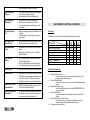
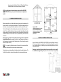
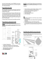
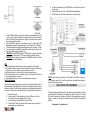
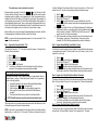
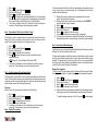
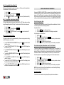
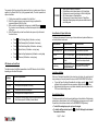
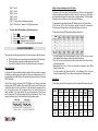
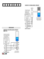
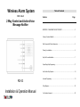
Wireless Alarm System
With Inbuilt
Table of Contents
Section
Page
2 Way Control and Active Voice
Message Notifier
IMPORTANT – PLEASE READ THIS SECTION FIRST…………………………………………..2
Features, Functions & Benefits……………………………………………………………………….3
Main Components & Optional Accessories………………………………………………………….5
Planning Your Installation …………………………………………………………………………….6
Easy Do-It-Yourself Installation……………………………………………………………………….7
Simple Step-by-Step Programming…………………………………………….…………………….11
User Guide for Easy Operation…………………………………………………..…………………...16
RD-03
Advanced Programming………………………………………………………………..……………...21
Wiring Diagrams………………………………………………………………………………………. 23
Installation & Operation Manual
Your Questions Answered ……………………………………………………………………………25
and/or damage to property or other loss, whether direct, indirect, incidental, consequential
or otherwise, based on a claim that the Product failed to function.
IMPORTANT – PLEASE READ THIS SECTION FIRST
This is a Do-It-Yourself WIRELESS ALARM SYSTEM designed to help users protect themselves,
their loved ones and their property and personal possessions. Please read through the important
information below before getting started with the WIRELESS ALARM SYSTEM.
•
Carefully follow the instructions in this manual when installing, setting up and programming
the WIRELESS ALARM SYSTEM
•
Take special notice of any specified notes, or bullet points throughout this manual
•
Please take the following precautionary measures while handling and installing the
WIRELESS ALARM SYSTEM:
1.
2.
3.
4.
5.
6.
7.
8.
•
Keep the WIRELESS ALARM SYSTEM away from water or damp areas
Do not install the WIRELESS ALARM SYSTEM in direct sunlight or near
extreme heat
Do not install the WIRELESS ALARM SYSTEM near strong electrical
current or magnetic force
Avoid dropping the WIRELESS ALARM SYSTEM or placing it in an area
with strong vibration
Do not disassemble the product – Doing so will void the Warranty
Use only the provided Power Adaptor from supplier
The rechargeable backup battery MUST use 3 pieces of AA size 1.2volt /
1300mA Ni-Mh rechargeable batteries.
To maintain the WIRELESS ALARM SYSTEM and its optimal performance,
users should test the entire system every one to two weeks
The WIRELESS ALARM SYSTEM is considered a “Local Alarm” in most states and regions,
which may qualify for certain discounts on homeowner’s insurance. Please ask your insurance
company or authorized insurance agent for more details.
NOTE: The Manufacturer shall have no liability for any death, personal and/or bodily injury
FEATURES, FUNCTIONS & BENEFITS
Do-It-Yourself Wireless
System
•
•
•
No hard-wired installation necessary
Practically effortless screw-in or double-sided tape mounting
Up to 300 ft. range covers entire house, apartment, small
business, etc.
Easy Setup & Operation
•
•
•
Simple programming & operation
Very user-friendly features & functions
All setup & programming options are passcode-protected
Pocket Remote Control
•
Allows easy arming, disarming & emergency calls
directly from pocket-sized remote control
“Remote Control Disarm
Disable” Function
•
Disarm is only possible via the control panel keypad
code when switched to ON
“Away” & “At-Home”
Security Modes
•
Various programming & arming options for “Away” or
“At-Home” security
Entry/Exit Delay time
Countdown Warning
Tone
•
A warning tone is given upon “Arming” reminding you of
imminent siren activation if the premise is not vacated
during the exit period.
During initial entry to the premise you are also reminded to
disarm the control panel with an identical warning tone.
Entry/Exit Zone (Zone 1)
•
•
Allows users time to exit or enter alarmed zone
Countdown beeps alert users before arming
“Walk Through” Feature
(Zone 2)
•
Allows users to active Zone 2 without setting alarm off if
Zone 1 is active first, Useful to user can reach Control Panel
to deactivate alarm if Panel is not located directly next to
entrance area. Zone 2 to 5 will activate the system instantly
except Zone 2 if Zone 1 is activated first.
Built-in Loud Siren
•
•
Immediately deters intruders
Alerts users, neighbors & others of an alarm activation
Auto Dialer for alarm
notification
•
Automatically calls up to six specified phone numbers
upon alarm activation & plays pre-recorded Alarm
Notification Message
•
•
Allows call recipients to respond as necessary
Remote Operation via
Telephone
•
Call in to arm, disarm, monitor situation or even speak to
the intruder from anywhere in the world
Immediately respond to an Alarm Notification Call
Exclusive Integrated
Speakerphone
•
•
•
Allows for advanced 2-way voice communication
Monitor situation or speak directly to an intruder
Converse with emergency personnel during an on-site
crisis situation
One-button Emergency
Call
•
Make on-site emergency calls directly from Remote Control
or Keypad
Call out to emergency personnel during on-site panic or
crisis situations
•
•
Entry Chimes during
Alarm OFF mode
•
•
Signals whenever door is opened during Alarm OFF mode
Alerts whenever children or others enter or exit
Rechargeable Backup
Battery
•
Backup power for Control Panel in the event of a power
outage.
Back-up battery: 3 pieces of AA size 1.2 volt/1300mA
Ni-Mh rechargeable
•
Long-Life Sensor
Batteries
•
•
•
MT-02 Door/Window Sensors & Remotes Control use
12 volt/23A Alkaline battery.
MT-01 Door/Window Sensor use 9 volt Alkaline battery
Control Panel notifies users of any low-battery situation
Battery Low Alert
•
Alerts users of low battery status on Sensors/Transmitters
Tamper Protection
•
All detector covers and the control panel battery cover (except
the Remote Control)are prevented from deliberate removal
without first entering the “TEST” (Battery Change)mode
Any attempt to remove the covers will activate an alarm
•
“Memory Chip” Stores All
Programmed Data
•
EEPROM retains all programmed settings for each User
Function, even during power outages
Completely Expandable &
Customizable
•
•
Add any number of Wireless Sensors/Detectors to each zone
The expansion connector on control panel allows you to
connect to an external siren & strobe unit etc.
MAIN COMPONENTS & OPTIONAL ACCESSORIES
Kit Contents
The following chart list the contents of the Alarm System kit package you selected.
KIT NO.
COMBINATION
Control Panel
Wireless PIR Motion Detector
Wireless Door/Window Sensor
Wireless Pocket Remote
Telephone Line
Power Adaptor
Mounting Screws/Hardware
User Manual
Kit A
□
1 pc
1 pc
2 pc
2 pc
1 pc
1 pc
1 pc
1 pc
Kit B
□
1 pc
1 pc
1 pc
1 pc
1 pc
1 pc
1 pc
1 pc
Kit C
□
1 pc
2 pc
1 pc
2 pc
1 pc
1 pc
1 pc
1 pc
Kit D
□
Optional Add-on Accessories
•
•
•
•
•
•
Wireless Door/Window Sensor
- Used for doors and windows to alert system of burglary attempt, or any
entering or exiting of the alarmed zone
Wireless PIR Motion Detector
- Used to detect motion in any room or open area, while immediately alerting
system
Wireless Pocket Remote Control
- Used to Arm and Disarm system, and to make PANIC/EMERGENCY calls
during crisis situations
Wireless Smoke Detector
- Used to detect smoke/fire and immediately alert system of potential fire
situation
Wireless Indoor/Outdoor Loud Siren w/ Strobe
- Used indoors or outdoors to create piercing audible siren and visual
flashing red strobe light immediately upon alarm activation
Other accessories may be available
-
Accessories such as Wired Siren & Strobe Unit, Wireless Signal Extenders,
Wireless Doorbells, Shock Sensors and more may be available
NOTE: An unlimited amount of sensors/detectors can be used with the WIRELESS
ALARM SYSTEM. This allows you to expand and customize your security system as
needed.
PLANNING YOUR INSTALLATION
Before proceeding with any part of the installation you must give very careful consideration to the
location of detectors, the control panel and external siren unit. It would prove extremely useful if you
sketch a plan of your property and identify the optimum location of each component of the system.
The starter kit is designed to suit the smallest property and provide a significant improvement in
protection. The use of additional detectors is strongly recommended in larger buildings, for example
a home consisting of 4 rooms on the lower floor and 4 rooms on the upper floor should use at least
4 PIR Motion Detectors and 3 Door/Window sensors. It is possible to add any number of detectors
to each zone.
Detectors/sensors set to Zone 2 & Zone 3 will not activate the system when set into Partial
Arming (At-Home) Mode. As an example - this is ideal for use in Bedrooms and a Hallway so
that the system may be entered into Home Mode during the night thus allowing the occupants
access to the upper rooms only.
NOTE: It’s very import to install the alarm panel in the center of a house and ensure all the
detectors are positioned within the circled areas for optimum performance.
The picture below is a plan showing this type of dwelling and how best to position the detectors. The
Control Panel is positioned at a center point between detectors for optimum reception performance.
EASY DO-IT-YOURSELF INSTALLATION
Setup and installation of the WIRELESS ALARM SYSTEM is practically effortless, because all
of the sensors and detectors are wireless. If you follow the instructions carefully, you should
have no problem setting up and installing this system, and adding additional and optional
accessories as needed.
Please keep in mind that the factory default settings are specifically set up to simplify
the installation and programming. Although there are advanced setup and programming
options (see the “Advanced Programming”), they are NOT NECESSARY unless there are two
similar systems within wireless signal range of each other, or if you desire to change the Site
Code or Zones (see information below).
Model MT-01: Mount each MT-01 Wireless Door/Window Sensor using the included screws or
double-sided tape (tape not recommended for permanent mounting). Please follow the diagram
and details below.
Ready-to-Go Default Site Code & Zone Settings
NOTE: The factory defaults on all of the sensors are already set up with a generic Site Code
and the most applicable Zone depending upon the sensor (Door/Window Sensors for Zone 1
and PIR Motion Detectors for Zone 2).
The Site Code is what identities the sensors as being unique or different from other wireless
radio devices that maybe in close proximity. In most cases this will not need to be changed
unless 1) The Site Code default was incorrect and does not match with the other Site Code
settings; 2) There are two similar systems within wireless range of each other; 3) Unless
specifically desired by user. The procedure for changing the Site Code and Zone Settings can be
found in the “Advanced Programming”.
If no changes are necessary or desired, continue with the easy installation process that follows.
Wireless Door/Window Sensor Installation (Options MT-01 or MT-02)
Model MT-02: Mount each MT-02 Wireless Door/Window Sensor using the included screws or
double-sided tape (tape not recommended for permanent mounting). Please follow the diagram
and details below.
•
•
•
•
•
You will need one Reed sensor pre-wired with Transmitter, one Magnetic contact, and the
included screws or double-sided tape for each Door/Window Sensor setup
Reed sensor and magnetic contact should have a gap within 1 inch
Stretch out cord for best reception
Check the Site Code and Zone Code is correct
Install a 9 volt Alkaline battery
NOTE:
1. Avoid installing the Transmitter unit onto a metal door frame, as doing so will reduce the
wireless range dramatically.
2. Use the expansion connector to connect an additional wired Normal Close type (N/C) Magnetic
Contact if required
3. The Wireless Door/Window Sensor can be used to detect the opening of cabinets.
4. Any number of Wireless Door/Window Sensor can be used with the system providing they
have the identical Site Code and mounted within effective wireless range of the Control
Panel.
Wireless PIR Motion Detector Installation (PIR is an acronym for Passive Infra Red)
Mount the Wireless PIR Motion Detector utilizing the included mounting bracket and screws.
Please follow the diagram and details below.
•
•
•
•
You will need one Transmitter unit (with inbuilt Reed Sensor), one Magnetic Contact, and
the included screws or double-sided tape for each Door/Window Sensor setup
The Magnetic Contact and Transmitter must be line up as shown in the figure above.
Magnetic Contact should have a gap between 1 inch
Check the Site Code and Zone Code is correct
Install a 12 volt/23A Alkaline battery
5)
6)
7)
•
•
•
•
•
•
•
Connect the included Adaptor to the POWER jack on Control Panel, and plug into an
electrical outlet.
Install 3 pieces of AA size 1.2 volt / 1300mA Ni-Mh Rechargeable Battery
Refit the battery cover and ensure the Tamper switch is pressed properly.
Place the PIR Motion Detector indoors only. If possible, the recommended position is in the
corner of a room so that the logical path of an intruder would cut across the fan detection
pattern. PIR Motion Detectors respond more effectively to movement across the device
than to movement directly towards it.
Mount the PIR Motion Detector at a height between 2 and 2.5m. At this height the PIR
Motion Detector will have a maximum range of up to 12m with a field of view of 110 degree.
Tilt the Motion Detector facing slightly downward toward open area of room (approx. 14° angle)
If you have a pet, place the included Pet-Immune Sticker on the lowest portion of the screen
Install a 9 volt alkaline battery and refit the cover.
IMPORTANT: Set the NORM/TEST switch to “NORM” mode for normal use (see diagram
above middle). The default is set to “TEST” mode for positioning and testing purpose.
IMPORTANT: When the battery is first connected to the PIR Motion detector a 2~3 minutes
period must be allowed for “Warming up”.
NOTE:
1. Avoid locating the detector facing a window or where it is exposed to or facing sunlight.
2. Avoid locating the detector in areas which contain objects likely to produce a rapid change in
temperature, such as central heating, ventilator, radiator. boiler, ducts etc.
3. Avoid locating the detector in a position where it is subject to excessive vibration.
4. Make sure the detection area is not obstructed by curtains, large furniture, plants which etc
which may block the pattern of coverage.
5. Avoid installing 2 PIR detectors in one room protecting the same coverage area.
Control Panel Installation
Follow the step-by-step instructions below in accordance with the diagram. Please note that it is
best to centralize the Control Panel within the alarm site to achieve the best wireless range and
functionality. If desired, the Control Panel can be mounted on a wall by utilizing standard screws and
the screw slot on the back of the Control Panel along with the screw hole under the battery cover.
1)
2)
Open the battery cover.
Connect one end of the included telephone line into the LINE jack on the Control
Panel, and the other end into a telephone jack on the wall.
3) Connect a telephone to the PHONE jack on the Control Panel.
4) Connect the ES-01 Wired Loud Siren with Strobe (optional accessory) according to
wiring diagram shown in the figure below.
*NOTE: Because the battery is protected by a Tamper Switch the Control Panel must be set to
TEST Mode when mounting the Control Panel, replacing the rechargeable backup batteries or
wiring the optional wired accessories,
SIMPLE STEP-BY-STEP PROGRAMMING
The following programming instructions will take you through the entire programming in a simple
step-by-step format. All programming is accomplished by utilizing the keypad on the Control
Panel, while confirmation tones (or beeps) will confirm that the programming was correct and
entered, or incorrect and not entered. The confirmation tones are as follows, unless otherwise
specified:
One long beep = Correct and entered
Three quick beeps = Incorrect and must be re-entered
Programming begins by entering a Function Key P or L or S then your Passcode, and then
the proper function will display to show on the LED screen. You would then enter the specific
programming options as stated in each programming step. When that programming step is
completed, wait until the LED display is off, followed by 3 quick beeps. Then proceed to the
next programming step as desired. The Control Panel utilizes Intelligent Storing Capability to
store programming information (data). Once you have entered the programming data for any
function, the Control Panel will automatically store that data. The data will remain secure in the
unit’s memory until changed by a user, even in the event of a power failure or outage.
Keep in mind that you can, at any time, change the programmed settings of any function. Just follow
the programming steps of the particular function you would like to change.
NOTE: If you pause while entering programming sequence, the unit may not accept it. If this
occurs, enter the sequence again.
the Alarm Notification Call and decide whether it may be a false alarm or not. Then the call
recipient can call 911, the police or other emergency assistance if deemed necessary.
1)
2)
3)
4)
5)
6)
Enter the P key
Enter your new (or default) Passcode: x x x x
Wait until the LED displays “P”
Enter the 1 key to program the first phone number to be dialed (For each of the
second through sixth phone numbers, repeat this entire programming stage and enter
2 ~ 6 at this step)
Enter the phone number of choice, up to 16 digits including pauses (For dialing out on
a PBX system or similar, you can add a “pause” to the phone number by entering Ý
within the number. For example, 9*12125551212 would dial 9, then pause for 2
seconds, then dial 1, the area code and number)
Within a few seconds you will hear a confirmation tone, and the information is stored
(One long beep = correct entry / Three quick beeps = incorrect entry must be
re-entered). The LED will flash the programmed phone number for confirmation.
Step 1 – Program User Passcode (Default: 1 2 3 4)
Step 3 – Program Automatic Dialing Cycles (Default: 2 cycles)
The default User Passcode is “1 2 3 4” and can be changed if necessary. To change the User
Passcode, follow the steps below.
This function is for users to program the amount of times the system will dial the entire sequence
of programmed phone numbers. The factory default is set up for 2 times (2 cycles). You can
program it for up to 9 cycles.
1)
2)
3)
4)
5)
6)
Enter the P key
Enter the default Passcode: 1 2 3 4
Wait until the LED displays “P”
Enter the Ý key
Enter your new 4-digit Passcode
You will hear a confirmation tone, and the information is stored (One long beep =
correct entry / Three quick beeps = incorrect entry must be re-entered)
How to manually reset back to the factory settings?
If you forgot your Passcode, or want to reset the system to its original defaults, follow the
procedure below to perform a Global Reset (resets Passcode and all programming
functions to the factory defaults):
Unplug the Power Adaptor and remove the Rechargeable Backup Batteries
Press and hold the Ý and # keys at the same time
While holding down the keys, plug in the Power Adaptor to power unit on
After one second, the unit will beep to confirm that the Global Reset was
successful
5) The Passcode and all User Functions will be set to the factory defaults
1)
2)
3)
4)
If Global
Reset was
unsuccessful,
repeat the same procedure above
Step 2NOTE:
– Program
Auto-Dialer
Telephone
Numbers
This function allows for up to six phone numbers to be entered into the Auto-Dialer, each of which
will be called in sequence in the event of an alarm activation.
NOTE: In most cases, it is recommended to have the system call out to users, family members,
neighbors and so on, rather than to 911 or the police. This allows a call recipient to respond to
1)
2)
3)
4)
5)
6)
Enter the P key
Enter your new (or default) Passcode: x x x x
Wait until the LED displays “P”
Enter the 7 key (Command Code for this function)
Enter 1 ~ 9 depending on the amount of cycles you desire
Within a few seconds you will hear a confirmation tone, and the information is stored
(One long beep = correct entry / Three quick beeps = incorrect entry must be re-entered)
Step 4 – Program Zone 1 Entry/Exit Delay Time (Default: 20 seconds)
This function is for users to enter the Zone 1 entry/exit delay time during Full Arming or Partial Arming
Mode. The factory default is 20 seconds. You can program from 0 ~ 90 second entry/exit delay.
Enter the P key
Enter your new (or default) Passcode: x x x x
Wait until the LED displays “P”
Enter the 8 key (Command Code for this function)
Enter 0 ~ 9 depending on the amount of delay time you desire (This number will be
automatically multiplied by 10 for the actual amount of seconds)
6) You will hear a confirmation tone, and the information is stored (One long beep =
correct entry / Three quick beeps = incorrect entry must be re-entered)
Step 5 – Program Alarm/Siren Duration (Default: 4 minutes)
1)
2)
3)
4)
5)
This function is for users to program the duration (length of time) that the siren will sound upon
alarm activation. The factory default is 4 minutes. You can program from 0 ~ 18 minutes.
1)
2)
3)
4)
5)
6)
Enter the P key
Enter your new (or default) Passcode: x x x x
Wait until the LED displays “P”
Enter the 9 key (Command Code for this function)
Enter 0 ~ 9 (This number will be automatically multiplied by 2 for the actual amount
of minutes. For example, 8 will actually equal 16 minutes) depending on the length of
time you want the siren to sound (Entering “0” turns the Siren feature off)
You will hear a confirmation tone, and the information is stored (One long beep =
correct entry / Three quick beeps = incorrect entry must be re-entered)
Step 6 – Program Remote Call-In Ring Cycle (Default: 6 Rings)
This function is for users to program the amount of rings before the system picks up during a
Remote Call-In (calling in to system from anywhere in the world to arm, disarm, monitor or
speak). The factory default is 6 rings, but you can program up to 9 rings.
1)
2)
3)
4)
5)
Enter the P key
Enter your new (or default) Passcode: x x x x
Wait until the LED displays “P”
Enter the 0 key (Command Code for this function)
Enter 0 ~ 9 depending on the amount of rings you want before the system
automatically picks up
6)
NOTE: Entering “ 0 “ will turn the Remote Call-In feature to OFF.
You will hear a confirmation tone, and the information is stored (One long beep =
correct entry / Three quick beeps = incorrect entry must be re-entered)
Step 7 – Site Code Learning from Pocket Remote Control
This function allows the Control Panel to “learn” the security system Site Code from the Remote
Control. The Remote Control must be set with the master code, and all other detectors must be
set with the same Site Code as the Pocket Remote. It is best to use the factory default setting
unless absolutely necessary (See “Advanced Programming”).
Please note:
Remote Control is the only component in the system for Site Code learning.
Enter the L key
Enter your new (or default) Passcode: x x x x
Wait until the LED displays “L”
Enter the # key (Command Code for this function)
Push any button on the Pocket Remote
You will hear a confirmation tone, and the information is stored (One long beep =
correct entry / Three quick beeps = incorrect entry must be re-entered)
Step 8 – Ring Back Tone Learning
1)
2)
3)
4)
5)
6)
This function allows the Control Panel to “learn” the unique telephone ring back specific to user’s
country or locale. This is a very simple procedure, but it is extremely important to the entire
operation of the Auto-Dialer feature.
1)
Make sure that a telephone number has been programmed into phone number
position 1 before beginning this procedure
2) Make sure that the person on the other end of that telephone number DOES NOT
pick up the telephone during this procedure
3) Enter the L key
4) Enter your new (or default) Passcode: x x x x
5) Wait until the LED displays “L”
6) Enter the Ý key (Command Code for this function)
7) The system will dial the telephone number in position 1 automatically
8) The system will emit one beep tone to confirm that the Ring Back Tone Learning has
been completed successfully / Three quick beeps = incorrect entry must be re-entered.
Step 9 – Record Alarm Notification Message
This function is for users to record the Alarm Notification Message that will play during an Alarm
Notification Call. The total recording time is 20 seconds.
It is best to use this message to notify that there has been an alarm activation, and also to specify
exactly how the call recipient can respond (listen in, monitor, speak, control auto-dialing or replay
message). The following script can be used as a guide on how to word your message. Make
sure that you speak clearly and steadily, approximately ten inches from the microphone. Keep
in mind that you have exactly 20 seconds of recording time.
Message Script suggestion:
“This is (your name). An alarm has been activated at (address). After the tone, press 4 to listen,
5 to speak, 6 to dial next number, 7 to replay this message, and 8 to stop dialing and disconnect.”
1)
2)
3)
4)
5)
6)
Enter the P/R key
Enter your new (or default) Passcode: x x x x
Wait until the LED displays “├”
Enter the # key (Command Code for this function)
Begin recording the message for up to 20 seconds
At the end of the 20 seconds you will hear a confirmation tone, and the message is stored
(One long beep = correct entry / Three quick beeps = incorrect entry must be re-entered)
*To replay the message, repeat steps 1, 2 and 3, then enter Ý to hear the message.
Step 10 – Program Built-In Siren (Default: ON)
This function allows the built-in loud siren to be turned on or off in the event of an alarm situation.
The default mode is ON for the built-in loud siren.
1)
2)
3)
4)
Enter the S key
Enter your new (or default) Passcode: x x x x
Wait until the LED displays “S”
Enter the 2 key to turn siren OFF, or enter the 3 key to turn siren ON (default mode is ON)
Step 11 – Program Door Chime Function (Default: ON)
This function allows the door chime sound to be turned ON or OFF while entering or exiting
during Disarming Mode (Alarm OFF Mode). The default mode is ON for the door chime sound.
1)
2)
3)
4)
Enter the S key
Enter your new (or default) Passcode: x x x x
Wait until the LED displays “S”
Enter the 4 key to turn door chime OFF, or enter the 5 key to turn door chime ON
(default mode is ON)
Step 12 – Check Programmed Settings
This function is used to check the programmed settings. These are one-key operations utilizing
the LED to display the current setting.
•
•
•
•
•
•
•
To check STORED TELEPHONE NUMBERS: Press any of the 1 ~ 6 keys and the LED will
display the number
To check AUTOMATED DIALING CYCLES: Press the 7 key and the LED will display the
stored amount of cycles
To check ENTRY/EXIT DELAY TIME: Press the 8 key and the LED will display the amount
of seconds
To check the ALARM/SIREN DURATION: Press the 9 key and the LED will display the total
amount of minutes
To check REMOTE CALL-IN RING CYCLE: Press the 0 key and the LED will display the
number of ring cycles
To check the LAST ACTIVATED ZONE: Press the # key and the LED will display the last
Zone activated from the Alarm Activation Memory
To check LOW BATTERY STATUS: Press the Ý key and the LED will display the Zone in
which there is a sensor/detector with a low battery
USER GUIDE FOR EASY OPERATION
Operating the WIRELESS ALARM SYSTEM is a pleasure, thanks to the Remote Control and the
user-friendly operating procedures. Some functions can be operated utilizing the Remote Control,
keypad on the Control Panel, or from anywhere in the world via the Remote Call-In feature
which allows users to operate the system from any telephone. The following operating instructions
will help you to fully benefit from the many features and functions of the WIRELESS ALARM SYSTEM.
Enter Full Arming (Away) Mode
This function is used to arm the entire system (all Zones) and all sensors/detectors. It is best to
use Full Arming Mode whenever leaving the premises.
Using Remote Control–
1) Press the MODE button on the Remote Control
2) You will hear one chirp as a confirmation, and the setting is accomplished
Using the keypad on the Control Panel –
1) Enter the S key
2) Enter your new (or default) Passcode: x x x x
(One beep = correct entry / Three quick beeps = incorrect entry must be re-entered)
3) Wait until the LED displays “S”
4) Enter the 1 key (Command Code for this function)
5) After the confirmation tone you will hear one beep, and the setting is accomplished
Enter Partial Arming Mode (At-Home Mode - Zones 2 & 3 Are Disabled)
This function is used to arm only the perimeters of the system (Zones 2 & 3 are disabled). It is
best to use Partial Arming Mode as an “At-Home” security mode whenever remaining on the
premises. This allows you to roam within your alarmed premise (home, office, etc.) without activating
the PIR Motion Detectors, while the perimeters (doors, windows, etc.) will remained armed.
Partial Arming Mode can only be entered using the keypad on the Control Panel as follows:
1)
2)
3)
4)
5)
Enter the S key
Enter your new (or default) Passcode: x x x x
(One beep = correct entry / Three quick beeps = incorrect entry must be re-entered)
Wait until the LED displays “S”
Enter the # key (Command Code for this function)
After the confirmation tone you will hear one beep, and the setting is accomplished
NOTE: When entering Full Arming & Partial Arming Modes, the unit will emit Entry/Exit delay
time countdown beeps after the confirmation tone.
Enter Disarming Mode
This function is used to disarm the entire system (all Zones) and all sensors/detectors.
Using Remote Control–
1) Press the MODE button on the Remote Control
2) You will hear three chirps as a confirmation, and the setting is accomplished
Using the keypad on the Control Panel –
1) Enter the S key
2) Enter your new (or default) Passcode: x x x x
(One beep = correct entry / Three quick beeps = incorrect entry must be re-entered)
3) Wait until the LED displays “S”
4) Enter the 0 key (Command Code for this function)
5) After the confirmation tone you will hear three beeps, and the setting is accomplished
Enter Emergency/Panic Alarm
5)
6)
Activate each of the sensors/detectors (one at a time)
The Control Panel will emit beep sounds as each detector is activated to confirm proper
operation. The number of beeps indicates the corresponding Zone of the sensor/detector.
NOTE: A doorbell sound indicates a low battery in the sensor/detector. This function
is also useful to identify which of the sensors set to the same zone has a low battery.
To Exit Test Mode (and enter Disarming Mode) using the keypad on the Control Panel:
1)
2)
3)
4)
5)
Enter the S key
Enter your new (or default) Passcode: x x x x
(One beep = correct entry / Three quick beeps = incorrect entry must be re-entered)
Wait until the LED displays “S”
Enter the 0 key (Command Code for this function)
After the confirmation tone you will hear three beeps, and the setting is accomplished
This function is used to activate the alarm during an on-site emergency or panic situation.
Responding During an Alarm Notification Call
Using Remote Control–
1) Press the PANIC button on the Remote Control
2) The system will immediately activate the alarm, sound the siren and immediately
begin dialing the programmed phone numbers
This function is used for call recipients to respond to an Alarm Notification Call. Call recipients
will have the option to monitor/listen in (via built-in microphone on Control Panel), speak (via
built-in 2-way speakerphone feature), have the system hang up and dial the next programmed
phone number, have the system stop dialing all programmed phone numbers, or replay the
Alarm Notification Message. This can all be accomplished by pressing specified keys on any
telephone keypad, from anywhere in the world.
Using the keypad on the Control Panel –
1) Press the PANIC button on the control panel.
2) The system will immediately activate the alarm, sound the siren and immediately
begin dialing the programmed phone numbers
NOTE: This button can also be used to enter a 2-way speakerphone call during an
incoming phone call (never to be used for outgoing phone calls, doing so will
activate the alarm “Panic”).
Enter Test Mode (Battery Change Mode)
This function is used to test the entire system (all Zones) and all sensors/detectors, ensure that
the sensors/detectors are installed within wireless range of the Control Panel, and that they are
working properly. This is also used for “Battery Change” as the tamper switches are disabled
thus allows detector covers to be removed to replace batteries.
NOTE: Testing of your system should be done on a regular basis to ensure that the system and
the sensors/detectors are working properly. This will also help you to gain a better understanding of
the capabilities of the system, and should help to eliminate any malfunction during a crisis situation.
To Enter Test Mode using the keypad on the Control Panel –
1)
2)
3)
4)
Enter the S key
Enter your new (or default) Passcode: x x x x
(One beep = correct entry / Three quick beeps = incorrect entry must be re-entered)
Wait until the LED displays “S”
Enter the Ý key (Command Code for this function). You will hear a “ding dong” as
confirmation.
Upon an alarm activation, the Auto-Dialer will call out to each of the programmed phone numbers
and play the Alarm Notification Message (as recorded by user). The call recipient’s procedure
and options are as follows:
1)
2)
Answer the call, then wait for the pre-recorded Alarm Notification Message to finish playing
Within 10 seconds after you hear the confirmation tone, press a key for the desired
function as follows:
•
Press 4 to Monitor/Listen in
•
Press 5 to Speak via 2-way Speakerphone
•
Press 6 to have system Hang Up and Dial Next Programmed Phone Number
•
Press 7 to Replay the Alarm Notification Message
•
Press 8 to have system Stop Dialing all Programmed Phone Numbers and
Disconnect Call
Remote Access from Any Outside Telephone
This function allows users to call in from anywhere in the world to access the system. Users calling
in will have the ability to enter the system into Full Arming Mode or Disarming Mode, as well as
monitor/listen in (via built-in microphone on Control Panel) or speak (via built-in 2-way speakerphone
feature). This can all be accomplished by pressing specified keys on any telephone keypad,
while calling in from anywhere in the world.
•
•
•
MODE/MEMO •
•
•
The user must call into the system, and the system should pick up in a certain amount of rings as
specified by the Remote Call-In Ring Cycle (programmed earlier). The caller’s procedure and
options are as follows:
1)
2)
3)
4)
Call the phone number that is connected to the Control Panel
Wait for the system to answer in correct amount of rings (as specified while
programming Remote Call-In Ring Cycle)
When you hear the confirmation tone, enter your new (or default) Passcode: x x x x
(If you enter an incorrect Passcode, you will hear three beeps and the telephone line
will hang up)
Within 10 seconds after you hear the confirmation tone, press a key for the desired
function as follows:
•
Press 1 to Enter Full Arming Mode (Confirmation = one beep)
•
Press 0 to Enter Disarming Mode (Confirmation = three beeps)
•
Press # to Enter Partial Arming Mode (Confirmation = two beeps)
•
Press 4 to Monitor/Listen in (Confirmation = one long beep)
•
Press 5 to Speak via 2-way Speakerphone (Confirmation = one long beep)
•
Press 8 to Disconnect (Confirmation = one long beep)
Alarm Situations & System Notifications
The following table represents the various types of alarm situations and system notifications, as
well as the probable cause for each.
LED Indicators on Control Panel
The table below shows the light/flash representations of each LED Indicator on the Control Panel,
depending upon the status of the system.
LED
Indicator
Light/Flash Representation
Steady light when keypad is in operation
Flashes twice per second when system is in Full Arming Mode
Flashes once per second when system is in Partial Arming Mode
LED off when system is in Disarming Mode
Flashes once per 2 seconds when system is in Testing Mode
Steady light with warning beeps when system was activated when last
set to Arming mode
Alarm Situation
Burglary
System Notification
Alarm & Loud Siren activate
Probable Cause
Intrusion or break-in at premises
Panic/Emergency Call
Alarm & Loud Siren activate
A crisis situation at premises
Line Cut
LINE CUT indicator lights
Tel. line has been disconnected or cut
Tamper
Alarm & Loud Siren
activate
RF LINK / LOW BAT
indicator flashes and control
panel gives slow beeps
Control Panel or one of the
detectors has a tamper situation
Low Battery
One of the detector transmitters in
the system has a low battery
Low battery notification
When one of the detector transmitters in the system has a low battery, the control panel will
beep (one beep per 3 seconds) to remind the user, and the RF LINK/LOW BAT LED will flash.
AC POWER
•
Steady light when power is normal
•
TEL LINK
•
Steady light when telephone line is linking
RING
•
Flashes when there is an incoming call
•
LINE CUT
•
Steady light when the telephone line is cut
Alarm Activation Memory
RF LINK
•
•
Flashes when receiving signals from sensors/detectors/transmitters
Slow flashes represent Low Battery of sensor/detector
This feature records the last Zone that was activated during an Alarm Activation. When disarming
system after any Alarm Activation, the Control Panel will beep (one beep per second) to remind
the user that an alarm has been activated, and the MODE/MEMO LED lights steady.
To check the Zone of the Sensor/Transmitter with a low battery, press the Ý key. The LED
will display the Zone number that the sensor operates on. Replace the battery right away.
Before removing the battery cover on any detector transmitters, ensure the system is set to
TEST mode to avoid initiating an alarm.
• To shut off the warning beeps, push any key on the keypad.
• To check the last Zone activated, press the # key. The LED will display the last activated
Zone number as follows:
Digit “1” = Zone 1
Digit “2” = Zone 2
Digit “3” = Zone 3
Digit “4” = Zone 4
Digit “5” = Zone 5
Digit “6” = Zone 6
Digit “7” = Tamper or Panic from wireless accessories
Digit “9” = Panic button or Tamper on Control Panel was activated
•
To clear the Alarm Activation Memory, follow the steps below:
1)
2)
3)
4)
5)
Enter the P key
Enter your new (or default) Passcode: x x x x
Wait until the LED displays “P”
Enter the # key (Command Code for this function)
The LED will display “0” “0” to confirm the programming is successful
Setting the Sensors/Transmitters to Specific Zones
This system has Six “Zones” plus a Panic/Tamper Zone, each of which can be triggered during
various alarm situations (see Active Zones below). These Zones can help you to pinpoint which
sensor/transmitter was triggered in an alarm situation or system notification. The factory default
Zone settings are fine for most users, but can be changed if necessary.
The wireless detector transmitters use twelve DIP Switches to set the Site Code and Zones
(1-9 for Site Code; 10-12 for Zone). The settings for switches 10 through 12 will determine the
Zone that a sensor will trigger when an alarm is activated, battery is low and so on.
The figure below shows the DIP Switch settings for each particular Zone.
ADVANCED PROGRAMMING
This section is for advanced programming options and should only be used in the following cases:
•
•
•
The Site Code default was incorrect and does not match with the other Site Code settings
There are two similar systems within wireless signal range of each other
You would like to change the Site Code or Zones for extra security or other reasons
Setting the Site Code
In order to prevent from any unauthorized attempt to operate or disarm your system, it’s necessary
to configure your system to accept radio signals only from your own system accessories. This is
done by setting a series of DIP switches in all accessories (except the control panel) to the same
ON/OFF combination.
The Site Code is set up by moving each of the 9 DIP switches in each accessory to the same
randomly selected ON/OFF sequence. When setting the DIP switches, ensure that each switch
‘clicks’ fully into position. Use the tip of a ball pen or a small screwdriver to move each switch in
turn. The figure below shows a Site Code example setting for the Remote Controls and all
detector transmitters. If you change the Site Code, you must re-program the Control Panel to
match the same code. This can be accomplished by following the procedure in “Step 7 – Code
Learning from Remote Control” in the Simple Step-by-Step Programming section.
* You should normally set your Door/Window sensor to Zone 1 as this is the only zone that
allows sufficient time to disarm you system when entering the premises.
* Zone 2 to Zone 5 are Instant Zone which activate an alarm instantly when system was set to
Full Arming (Away) mode.
* Detectors/sensors set to Zone 2 & Zone 3 will not activate the system when set into Partial
Arming (At-Home) mode.
* You should normally set the Wireless Smoke (Fire, or Gas) Detectors to Zone 6 which will
activate the system instantly 24 hours a day even the system is set to Disarming mode.
Active Zones
The table below shows which Zones are active in the various modes that the system can be set to.
MODE
Full
Arming
Mode
Partial
Arming
Mode
Disarming
Mode
ZONE 1
(Entry/Exit)
ZONE 2
(Instant)
ZONE 3
(Instant)
ZONE 4
(Instant)
Active
Active
Active
Active
Active
Not
Active
Not
Active
Active
Not
Active
Not
Active
Not
Active
Not
Active
ZONE 6
(24-HR,
Smoke,
etc.)
PANIC/
TAMPER
(24-HR)
Active
Active
Active
Active
Active
Active
Active
Active
ZONE 5
(Instant)
Not
Active
Battery
Check
Not
Active
Not
Active
Not
Active
Not
Active
WIRING DIAGRAMS
Not
Active
Not
Active
Not
Active
YOUR QUESTIONS ANSWERED
1. What to do if I forget my keypad Passcode?
If you forgot your Passcode, or want to reset the system to its original defaults, follow the
procedure below to perform a Global Reset (resets Passcode and all programming functions
to the factory defaults):
1)
2)
3)
4)
5)
Unplug the Power Adaptor and remove the Rechargeable Backup Batteries
Press and hold the Ý and # keys at the same time
While holding down the keys, plug in the Power Adaptor to power unit on
After one second, the unit will beep to confirm that the Global Reset was successful
The Passcode and all User Functions will be set to the factory defaults
2. When I switch to NORMAL mode the PIR stops working. Why?
A PIR that works in TEST mode will always work, when switched to NORMAL mode, please
be aware of the following points:
- The red indicator will not function in NORMAL mode. This is correct and is designed to
increase the battery life.
- The PIR will sleep for 4 minutes when movement has been detected. Whilst sleeping, the
PIR will not detect movement. After the sleep period the PIR will beginning detecting again.
- The PIR will not function with the cover removed. Please ensure the cover is fully in place.
3. Why do my batteries only last a few months in the PIR Motion Detector?.
- Check the battery connections are tight especially if you are using duracell as this make of
battery has an unusually narrow positive nipple.
- Make sure you have not left the switch in the PIR set to TEST mode.
4. What is the “Walk Through” function and how to use it?
A sensor set to Zone 2 will give you Entry/Delay time period ONLY if a Zone 1 sensor has
been triggered first. If NOT, the sensor will trigger the alarm immediately. If set, normally
used for a PIR in your entrance.
5. Why can I not get a very good range with any of my detectors or remote control?
The system is designed for use up to 80 meters from the control panel in clear space
with low back ground RF noise conditions. The range is also influenced by the number of
walls between your detectors and control panel. Try to remain with in 18 meters of the
control panel and do not install the control panel close to metal objects or inside cupboards.
6. When I walk in front of a PIR Motion Detector the siren sounds immediately when the
system is in Disarm mode. Why?
You have not set up your zone code correctly on the switch bank inside the detector or you
have not fitted the cover back on the detector properly - check the Tamper switch operation.