1
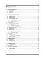
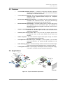
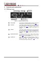
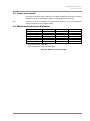
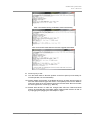
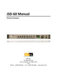
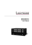
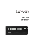
HDMI-TPS-TX90/RX90 User’s Manual Page 2 / 31 HDMI-TPS-TX90/RX90 User’s Manual SAFETY INSTRUCTIONS Class II apparatus construction. This equipment should be operated only from the power source indicated on the product. To disconnect the equipment safely from power, remove the power cord from the rear of the equipment, or from the power source. The MAINS plug is used as the disconnect device, the disconnect device shall remain readily operable. There are no user-serviceable parts inside of the unit. Removal of the top cover will expose dangerous voltages. To avoid personal injury, do not remove the top cover. Do not operate the unit without the cover installed. The apparatus shall not be exposed to dripping or splashing and that no objects filled with liquids, such as vases, shall be placed on the apparatus. The apparatus must be safely connected to multimedia systems. Follow instructions described in this manual. WEEE (Waste Electrical & Electronic Equipment) Correct Disposal of This Product This marking shown on the product or its literature, indicates that it should not be disposed with other household wastes at the end of its working life. To prevent possible harm to the environment or human health from uncontrolled waste disposal, please separate this from other types of wastes and recycle it responsibly to promote the sustainable reuse of material resources. Household users should contact either the retailer where they purchased this product, or their local government office, for details of where and how they can take this item for environmentally safe recycling. Business users should contact their supplier and check the terms and conditions of the purchase contract. This product should not be mixed with other commercial wastes for disposal. Page 3 / 31 DECLARATION OF CONFORMITY We, Lightware Kft. 15 Peterdy Street, Budapest H-1071, HUNGARY as manufacturer declare, that the products HDMI-TPS-TX90 HDMI-TPS-RX90 (Computer Monitor Extender) in accordance with the EMC Directive 2004/108/EC and the Low Voltage Directive 2006/95/EEC is in conformity with the following standards: EMI/EMC ..................................... EN 55022 Class B Safety........... UL, CUL, GS, CR, RCM, PSE, Class II Date: 28 March 2012 Name: Gergely Vida (Managing Director) Signed: Page 4 / 31 HDMI-TPS-TX90/RX90 User’s Manual Table of contents 1. INTRODUCTION .............................................................................................................................6 2. GENERAL DESCRIPTION..............................................................................................................6 2.1. 2.2. 2.3. 2.4. 3. BOX CONTENTS ..........................................................................................................................6 DESCRIPTION .............................................................................................................................6 FEATURES ..................................................................................................................................7 APPLICATIONS ............................................................................................................................7 CONTROLS AND CONNECTIONS ................................................................................................8 3.1. TX90 FRONT VIEW ......................................................................................................................8 3.2. TX90 REAR VIEW ........................................................................................................................9 3.3. RX90 FRONT VIEW ................................................................................................................... 10 3.4. RX90 REAR VIEW ..................................................................................................................... 11 3.5. ELECTRICAL CONNECTIONS ...................................................................................................... 12 3.5.1. HDMI Input and Output.................................................................................................. 12 3.5.2. IR connectors ................................................................................................................ 12 3.5.3. Twisted Pair inputs and outputs .................................................................................... 13 3.5.4. RS-232 connectors ........................................................................................................ 13 4. INSTALLATION ........................................................................................................................... 14 4.1. MOUNTING OF HDMI-TPS UNITS .............................................................................................. 14 4.1.1. Rack shelf ...................................................................................................................... 14 4.1.2. Under desk mounting kit ................................................................................................ 14 4.1.3. Under desk mounting kit double .................................................................................... 14 4.2. CONNECTION BETWEEN TX90 AND RX90 ................................................................................. 15 4.3. INFRA-RED ACCESSORIES ........................................................................................................ 15 4.4. ETHERNET PORT ...................................................................................................................... 15 4.5. SERIAL DEVICES ...................................................................................................................... 16 4.5.1. General information about serial communication .......................................................... 16 4.5.2. Type of serial cables...................................................................................................... 16 4.5.3. Example connection diagrams ...................................................................................... 17 4.5.4. RS-232 mode switch ..................................................................................................... 17 5. OPERATION ................................................................................................................................ 18 5.1. 5.2. 5.3. 5.4. 6. POWERING DEVICES................................................................................................................. 18 STATUS LEDS ON TX90 AND RX90 .......................................................................................... 18 POWER SAVE MODE* ................................................................................................................ 19 MAXIMUM TWISTED PAIR DISTANCES ......................................................................................... 19 FIRMWARE UPDATE .................................................................................................................. 20 6.1. INFORMATION: ......................................................................................................................... 20 6.2. IMPORTANT NOTES ................................................................................................................... 20 6.3. DEVICE UPGRADE PROCESS ..................................................................................................... 20 6.3.1. Possible errors during firmware upgrade ...................................................................... 22 7. TROUBLESHOOTING ................................................................................................................. 23 7.1. THERE IS NO PICTURE .............................................................................................................. 23 8. SPECIFICATION .......................................................................................................................... 24 9. MECHANICAL DRAWINGS ........................................................................................................ 26 9.1. 9.2. HDMI-TPS-TX90 ................................................................................................................... 26 HDMI-TPS-RX90 ................................................................................................................... 28 10. WARRANTY .............................................................................................................................. 30 11. DOCUMENT REVISION HISTORY .......................................................................................... 30 Page 5 / 31 1. Introduction Thank you for choosing Lightware’s HDMI TPS series transmitter and receiver. The HDMI-TPS-TX90 and HDMI-TPS-RX90 twisted pair extenders provide extension of uncompressed Full-HD video for extreme distances over a single CATx cable. 2. General description 2.1. Box contents HDMI-TPS-TX90 (Transmitter) HDMI-TPS-RX90 (Receiver) Infra-Red Transmitter and Receiver pair User's Manual (This document) Quick Start Guide +12VDC universal wall plug power adaptor 2.2. Description The HDMI-TPS-TX90 and HDMI-TPS-RX90 are HDMI compliant long-distance Twisted Pair (TP) extenders. The units offer bi-directional RS-232, Infra-Red and Ethernet pass-through all on the same CAT5e...CAT7 cable that carries the video signal. Video resolutions up to 4K and 48 bit color depth, even 120 Hz 3D video signals are extendable, as well as the various embedded audio formats. The TPS extenders provide full HDCP and EDID compliance and work at all standard AV resolutions. Remote powering is available through the single CAT5e...CAT7 cable, but a local power supply can also be used. All devices can be mounted on a rack shelf or be used standalone formats. Page 6 / 31 Section 1. Introduction HDMI-TPS-TX90/RX90 User’s Manual 2.3. Features Two available firmware versions – To best fit to customers’ demands, Lightware provides two firmware versions. Users can maximize potential cable length or extended resolutions. 10/100 Ethernet extension – Don’t need a separate LAN cable anymore. Ethernet extension is also supported without having to use a separate twisted pair cable. Bi-directional RS-232 pass-through – AV systems can also contain serial port controllers and controlled devices. Serial port pass-through supports any unit that works with standard RS-232. Bi-directional IR pass-through – Infra-Red signals used by several devices are also supported by the TPS extender pair. The supplied IR Receiver and Transmitter integrate external IR devices into the extension system. Supports all HDMI resolutions, 3D video signal as well – High bandwidth allows extension of resolutions up to 4K and even 3D sources and displays are supported. Remote power through CATx cable – Only one wall plug adaptor powers both TX and RX units, one of them locally and the other one remotely. HDCP compliant – The TPS extenders support EDID pass through and HDCP encrypted HDMI signal transmission. Uncompressed video/audio up to 10.2 Gbps – HDTV signals up to 340 MHz pixel clock frequency are passed through regardless of their resolution. Rack mounting options – Several mounting methods ensure the universal usage. Units can be placed into standard racks or under flat surfaces. Locking DC connector – Special plug of wall adaptor ensures safe power supply. This type of connector prevents unwanted extractions. 2.4. Applications Figure 2-1. Typical standalone application Section 2. General description Page 7 / 31 3. Controls and connections 3.1. TX90 front view RS-232 mode RS-232 port 5 4 IR Input 2 IR Output 3 1 Status LEDs Figure 3-1. HDMI-TPS-TX90 front view Page 8 / 31 1 Status LEDs The LEDs give feedback about the state of units and video signal. (For more information see section 5.2.) 2 IR Output 2 pole TRS connector, also known as 3,5 mm (1/8”) jack plug for optional IR Transmitter only. (Pin assignment can be found in section 3.5.2) To install the IR Receiver and Transmitter pair correctly, please read section 4.3 carefully. 3 IR Input 3 pole TRS connector, also known as 3,5 mm (1/8”) jack plug for optional IR Receiver only. (Pin assignment can be found in section 3.5.2) To install the IR Receiver and Transmitter pair correctly, please read section 4.3 carefully. 4 RS-232 mode switch The RS-232 connection can be used to extend a serial data connection or for firmware upgrade. (Please read section 4.5.4 for more information.) 5 RS-232 port 9-pole D-sub female receptacle connector. Connect a serial cable between the HDMI-TPS-TX90 and the desired serial device. (See section 4.5 for more information about usage of serial port.) Section 3. Controls and connections HDMI-TPS-TX90/RX90 User’s Manual 3.2. TX90 rear view 4 DC +12V in 3 Ethernet port 2 TPS Output HDMI Input with locking receptacle 1 Figure 3-2. HDMI-TPS TX90 rear view 1 HDMI Input 19-pole standard HDMI connector. Connect a standard HDMI cable between the HDMI source and HDMI-TPS-TX90. Use locking receptacle if the plug has additional screw for safe connecting. (See section 3.5.1 for more information.) 2 TPS Output RJ45 receptacle connector. Connect a Twisted Pair cable between the HDMI-TPS-RX90 and HDMI-TPS-TX90. (See section 4.2 for more information.) 3 Ethernet port RJ45 connector. Connect a Twisted Pair cable between HDMI-TPS-TX90 and Local Area Network (LAN) device. Ethernet connection is optional. (See section 4.4 for more information.) 4 +12V DC in Connect the output of the supplied +12V power adaptor. CAUTION! Warranty void if damage occurs due to use of a different power source. (See section 5.1 for more information.) Section 3. Controls and connections Page 9 / 31 3.3. RX90 front view RS-232 mode RS-232 port 5 4 IR Input 3 2 IR Output 1 Status LEDs Figure 3-3. HDMI-TPS RX90 front view Page 10 / 31 1 Status LEDs The LEDs provide feedback about the state of units and video signal. (For more information see section 5.2.) 2 IR Output 2 pole TRS connector, also known as 3,5 mm (1/8”) jack plug for optional IR Transmitter only. (Pin assignment can be found in section 3.5.2) To install the IR Receiver and Transmitter pair correctly please read section 4.3 carefully. 3 IR Input 3 pole TRS connector, also known as 3,5 mm (1/8”) jack plug for optional IR Receiver only. (Pin assignment can be found in section 3.5.2) To install the IR Receiver and Transmitter pair correctly please read section 4.3 carefully. 4 RS-232 mode switch The RS-232 connection can be used to extend a serial data connection or for firmware upgrade. (Please read section 4.5.4 for more information.) 5 RS-232 port 9-pole D-sub female receptacle connector. Connect a serial cable between the HDMI-TPS-TX90 and the desired serial device. (See section 4.5 for more information about usage of serial port.) Section 3. Controls and connections HDMI-TPS-TX90/RX90 User’s Manual 3.4. RX90 rear view 4 DC +12V in 3 Ethernet port 2 TPS Input HDMI Output with locking receptacle 1 Figure 3-4. HDMI-TPS RX90 rear view 1 HDMI Output 19-pole standard HDMI connector. Connect a standard HDMI cable between the HDMI source and HDMI-TPS-TX90. Use locking receptacle if the plug has additional screw for safe connecting. (See section 3.5.1 for more information.) 2 TPS Output RJ45 receptacle connector. Connect a Twisted Pair cable between the HDMI-TPS-RX90 and HDMI-TPS-TX90. (See section 4.2 for more information.) 3 Ethernet port RJ45 connector. Connect a Twisted Pair cable between HDMI-TPS-TX90 and Local Area Network (LAN) device. Ethernet connection is optional. (See section 4.4 for more information.) 4 +12V DC in Connect the output of the supplied +12V power adaptor. CAUTION! Warranty void if damage occurs due to use of a different power source. (See section 5.1 for more information.) Section 3. Controls and connections Page 11 / 31 3.5. Electrical connections 3.5.1. HDMI Input and Output HDMI-TPS-TX90 and RX90 provide standard 19-pole HDMI connectors for input and output. Always use high quality DVI cable for connecting sources and displays. 19 17 15 13 11 9 7 5 3 1 1 3 5 2 18 16 14 12 10 8 6 4 1 2 3 4 5 6 7 8 9 10 4 6 9 11 13 15 17 19 8 10 12 14 16 18 2 HDMI Type A receptacle Pin 7 Signal TMDS Data2+ TMDS Data2 Shield TMDS Data2– TMDS Data1+ TMDS Data1 Shield TMDS Data1– TMDS Data0+ TMDS Data0 Shield TMDS Data0– TMDS Clock+ HDMI Type A Plug Pin Signal 11 12 13 14 15 16 17 18 19 TMDS Clock Shield TMDS Clock– CEC Reserved SCL SDA DDC/CEC/HEC Ground +5 V Power (max 50 mA) Hot Plug Detect Table 3-1. HDMI connector pin assignments 3.5.2. IR connectors IR Receiver and Transmitter connect to TPS units with TRS (Tip, Ring, and Sleeve) connectors. They are also known as (3,5 mm or approx. 1/8”) audio jack, phone jack, phone plug, and mini-jack plug. 123 123 Receiver: 3 pole TRS Transmitter: 2 pole TRS Receiver 1 Tip 2 Ring 3 Sleeve IR Input GND IR Input + Transmitter 1 Tip 2 Ring 3 Sleeve IR Output + IR Output IR Output - Table 3-2. TRS connector pin assignment for supplied IR accessories Info Page 12 / 31 Transmitter’s Ring pole is optional. If your IR Transmitter has three pole TRS plug, then the Ring and the Sleeve are the same signal (Output - ) Section 3. Controls and connections HDMI-TPS-TX90/RX90 User’s Manual 3.5.3. Twisted Pair inputs and outputs HDMI-TPS-TX90 and RX90 provide standard RJ45 connectors for TPS Input, Output and Ethernet. 1 8 1 8 RJ45 receptacle RJ45 plug Lightware recommends the termination of TP cables on the basis of TIA/EIA T 568 A or TIA/EIA T 568 B standards. TIA/EIA T568 A Pin color and name TIA/EIA T568 B color and name 1 white/green stripe white/orange stripe 2 green solid orange solid 3 white/orange stripe white/green stripe 4 blue solid blue solid 5 white/blue stripe white/blue stripe 6 orange solid green solid 7 white/brown stripe white/brown stripe 8 brown solid brown solid Table 3-3. Recommended termination of TP cables 3.5.4. RS-232 connectors Serial devices connect to TPS units with standard 9-pole D-subminiature connector. 5 1 9 6 D-sub 9-pin female (DE9F) Pin nr. RS-232 straight pin-out 1 6 5 9 D-sub 9-pin male (DE9M) RS-232 cross pin-out 1 NC - non connected NC - non connected 2 TX data transmit (output) RX data receive (input) 3 RX data receive (input) TX data transmit (output) 4 DTR (Internally connected to Pin 6) DTR (Internally connected to Pin 6) 5 GND signal ground (shield) GND signal ground (shield) 6 DSR (Internally connected to Pin 4) DSR (Internally connected to Pin 4) 7 RTS (Internally connected to Pin 8) RTS (Internally connected to Pin 8) 8 CTS (Internally connected to Pin 7) CTS (Internally connected to Pin 7) 9 NC - non connected NC - non connected Table 3-4. D-sub connector pin assignment for standard RS-232 Section 3. Controls and connections Page 13 / 31 4. Installation 4.1. Mounting of HDMI-TPS units To fix the extender units, Lightware supplies optional accessories for different usage methods. All kind of mounting kits have the similar fixing method. The TPS units have two mounting holes with inner thread on the bottom side. Secure the device by screwing the enclosed M3x6 mm cross recessed, countersunk head screws (DIN 965A) through two holes of the shelf into the TPS’ mounting hole. To order mounting accessories please contact Lightware LLC. 4.1.1. Rack shelf Allows rack mounting for half-rack, quarter-rack and pocket sized units. 1U high rack shelf provides mounting holes for fastening two half-rack or four quarter-rack sized units. Pocket sized devices can also be fastened on the shelf. 4.1.2. Under desk mounting kit The UD kit allows pocket sized units to be easily mounted on any flat surface (e.g. furniture) 4.1.3. Under desk mounting kit double The UD-kit double makes it easy to mount a single device or multiple devices on any flat surface (e.g. furniture). Page 14 / 31 Section 4. Installation HDMI-TPS-TX90/RX90 User’s Manual 4.2. Connection between TX90 and RX90 Connect one CAT5, CAT5e, CAT6a or CAT7 (recommended) cable between HDMI-TPS-TX90 transmitter and HDMI-TPS-RX90 receiver. The TPS line connection is not compatible with Ethernet devices. Do not connect either the TPS Output or TPS Input to a Local Area Network device or a PC. It might damage both devices. Warning: Do not connect any device to the Ethernet connectors unless you are sure they are compatible. Connecting incompatible devices with similar connectors may cause harm to the devices. 4.3. Infra-Red accessories IR receiver can sense IR light (e.g. emitted by a remote controller) and send electrical signals to the IR transmitter. The transmitter unit processes the electrical signals and emits IR light toward the controlled device (e.g. projector). This is a simplex communication between the IR receiver and IR transmitter, so IR OUT receptacle accepts only the IR transmitter and IR IN receptacle accepts only the IR receiver. IR accessories are not interchangeable. The IR messages received by the TX/RX90’s IR INPUT will be sent by the IR OUTPUT of the RX/TX90. Info: Direct line of sight is required between IR transmitter and the controlled device (e.g. Blu-Ray or DVD player) Info Direct line of sight is required between IR receiver and the controller device (e.g. remote controller) 4.4. Ethernet port HDMI-TPS units can also extend 10/100 Ethernet over the single CATx cable. It is a bi-directional communication between TX90 and RX90 so LAN devices (e.g. switch) can be connected either TX90 or RX90. Connect the LAN device to any TPS (typically TPS-TX90) unit and connect the network device (e.g. projector) to the other one (typically TPS-RX90). Warning: Avoid mixing the Ethernet and TPS lines! Section 4. Installation Page 15 / 31 4.5. Serial devices 4.5.1. General information about serial communication In our aspect there are two type of devices in general serial communication: Data Terminal Equipment – Data Terminal Equipment (DTE) is an end instrument that converts user information into signals or reconverts received signals. Typical DTE devices: computers, LCD touch panels and control systems. Data Circuit-terminating Equipment – Data Circuit-terminating Equipment (DCE) is a device that sits between the DTE and a data transmission circuit. It also called data communication equipment and data carrier equipment. Typical DCE devices: projectors, industrial monitors and amplifiers. Among others the pin assignment is different between DTE and DCE. DTE Pin 2: RD Pin 3: TD RD: Received Data (digital input) TD: Transmitted Data (digital output) Info: DCE TD RD HDMI-TPS-TX90 and RX90 are DCE units according to their pin-out. Different type of serial cables must be used between different serial devices. DTE DCE DTE Null-modem Straight DCE Straight Null-modem* * in general contact DCE with DCE by tail-circuit serial cable. To connect TX90 or RX90 and a DCE unit use male-male null-modem cable. 4.5.2. Type of serial cables Straight serial cable – straight pin-outs both ends Null-modem serial cable – straight pin-out at the one end and cross pin-out at the other end. (Interchange lines of TX and RX). For the detailed pin-outs see section 3.5.4. Page 16 / 31 Section 4. Installation HDMI-TPS-TX90/RX90 User’s Manual 4.5.3. Example connection diagrams The following cases are examples. Devices may have different receptacles and pin-outs. To extend RS-232 between controller system (DTE) and projector (DCE). Connect straight serial cable between controller system (DTE) and TX90 (DCE) and null-modem serial cable between RX90 (DCE) and projector (DCE). 1 Straight serial cable Null-modem serial cable 2 To extend RS-232 between computer (DTE) and computer (DTE). Connect straight serial cable between controller system (DTE) and TX90 (DCE) and straight serial le between RX90 (DCE) and computer (DTE). 1 Straight serial cable Straight serial cable 2 4.5.4. RS-232 mode switch Change the RS-232 operation mode switch between RS-232 pass-through and firmware update* mode. “Normal“ position – Enables bi-directional RS-232 extension for serial devices. A controller device (e.g. computer or serial touch panel) can be connected to either TX90 or RX90. Connect the devices according to section 4.5. “Prog” position – Firmware upgrade is available via serial cable. Always use straight serial cable for firmware upgrade. For more information see section 6. Section 4. Installation Page 17 / 31 5. Operation 5.1. Powering devices HDMI-TPS units are able to provide remote power for each other. It means that only one unit needs to be powered by the supplied power adaptor. The other one gets the power over the TPS connection. After the system setup is complete, connect the output of the +12V Power Adaptor to the HDMI-TPS-TX90 or the HDMI-TPS-RX90. Both units are immediately powered ON. The initialization of the units may take time up to 10 seconds. After this procedure the status LEDs provide information about the connection. The special locking DC plug provides safe connection. Plug the connector into the +12V 1A DC IN receptacle and twist 90° clockwise to lock it. Figure 5-1. Locking DC plug Info When building an electronic system, make sure that all of the devices are powered down before connecting them. Powered on devices may have dangerous voltage levels that can damage sensitive electronic circuits. 5.2. Status LEDs on TX90 and RX90 The LEDs give feedback about the state of units and video signal. HDCP: Indicates if the video stream is HDCP encrypted. If HDCP LED is off and VIDEO LED lights, then there is a video signal stream but it is not HDCP encrypted. VIDEO: Indicates if there is a video stream between source and display. If VIDEO LED is off there is no video signal transmission. LINK: It lights continuously if the transmitter and the receiver are connected with a CATx cable (units can communicate with each other on TPS line) and there is a data transmission. It blinks once every second if the transmitter and the receiver are in power save mode (only with normal firmware). See more information section 5.3. If the LINK LED does not light, then there could be errors with TPS connection. LIVE: It blinks once every two seconds if the unit is powered and ready to use. If the LED is off there is no powering or the device is out of order. Page 18 / 31 Section 5. Operation HDMI-TPS-TX90/RX90 User’s Manual 5.3. Power save mode* The units enter power save mode when no signal is detected on the input. Normal operation is restored automatically when any signal appears on the input. Info Power save mode is available only with normal firmware. Long reach firmware does not support low consumption mode. 5.4. Maximum twisted pair distances Resolution Pixel clock rate CAT5e cable CAT7** cable 1024 x 768 @60Hz 65,00 MHz 100m / 160*m 120m / 180*m 1280 x 720p @60Hz 73,84 MHz 100m / 160*m 120m / 180*m 1920 x 1080i @60Hz 74,25 MHz 100m / 160*m 120m / 180*m 1280 x 1024 @60Hz 108,00 MHz 100m / 160*m 120m / 180*m 1920 x 1080p @60Hz 148,50 MHz 100m / 150*m 120m / 170*m 1920 x 1200 @60Hz 152,90 MHz 100m / NA* 120m / NA* 1600 x 1200 @60Hz 162,00 MHz 100m / NA* 120m / NA* * with long reach firmware option. Long reach firmware supports pixel clock frequencies under 148,5 MHz ** CAT7 Twisted Pair cable recommended Table 5-2. Maximum TP cable length Section 5. Operation Page 19 / 31 6. Firmware update This section is about the update procedure of Lightware HDMI-TPS-TX90 and HDMI-TPS-RX90 long range extenders. 6.1. Information: The firmware update is recommended if a new version is released. It might also be necessary if serious problems occur with former (or later) versions. A 9-pole male-female RS-232 straight through cable has to be connected between a Windows based computer and the TPS device. The TPS devices can be updated separately. The device’s upgrade program works well with USB to RS-232 adapter but it is strongly recommended to use native serial port. Info: During the update continuous data transfer on TPS link is not guaranteed. 6.2. Important notes Beware of swapping transmitter’s and receiver’s firmware! Always upgrade TX90 with TX firmware and RX90 with RX firmware! Always use transmitter and receiver pair with the same firmware type (Long Reach with Long Reach, Normal with Normal) and version number! Do not power off the devices during upgrade progress! Do not plug or unplug any cable during upgrade progress! 6.3. Device upgrade process 1. Unzip the firmware package to a folder. 2. Select the desired type of firmware: a. “Normal” firmware supports all resolutions up to 120m distance* b. “Long reach” firmware supports lower resolutions up to 180m distance. For detailed information about available resolutions and cable lengths please read section 5.4. 3. Power on the transmitter: a. Attach the 12V DC 2.5A power adaptor to TX90 or b. Connect TPS line to the receiver, if RX90 is already powered. 4. Make sure the switch next to the RS-232 connector is in "Prog" position. 5. Attach the serial cable to TX90. The options of the serial data transfer are set up automatically. 6. Run the corresponding .bat file. The file name contains the suitable device’s type (e.g. TX_30.06_NORMAL.bat). 7. The update takes a few minutes, depending on the device type and the firmware size. The progress level is shown in the terminal window. Page 20 / 31 Section 6. Firmware update HDMI-TPS-TX90/RX90 User’s Manual After a successful burning verification starts automatically. After a successful verification the firmware upgrade terminates. 8. Press any key to exit. 9. Turn the switch back to "Normal" position on the front panel (not necessary for normal operation, but recommended) 10. Please update the firmware of the RX90 device too as both devices needs to have the same firmware type and version. The update process for the RX90 is nearly the same as for the TX90 except for the firmware itself. Be sure to select the same type as the TX has (e.g. “Normal”). 11. Restart both devices: to make the changes take effect the TX90 and RX90 need to be rebooted after a firmware update. Please power devices off and on by unplugging and plugging the wall adaptor in again. Section 6. Firmware update Page 21 / 31 6.3.1. Possible errors during firmware upgrade “Could not autodetect board connected to any uart port” Possible reason Serial cable is not connected properly: Device is not powered: USB to RS-232 adaptor is used: RS-232 mode switch in “Normal” position Solution Check if the serial cable is connected properly between the TPS device and the computer. If the LIVE LED is not blinking on the front panel check the power source adapter or TPS line. The device’s upgrade program usually works well with USB to RS-232 adapter but the use of native serial port is recommended. Switch it to “Prog” position. “Didn't get 'Ready' response for write operation.” In this case firmware upgrade is started, but doesn’t finish with success. Device’s firmware needs to be repaired. Repeat the firmware upgrade after fixing the possible connection problems. Possible reason Page 22 / 31 Serial cable unplugged during the process Device is powered off during process Solution Check if the serial cable is connected properly between the TPS device and the computer. If the LIVE LED is not blinking on the front panel check the power adapter or TPS line. Section 6. Firmware update HDMI-TPS-TX90/RX90 User’s Manual 7. Troubleshooting 7.1. There is no picture Check the cables Due to the high data rates, the cables must fit very well. If your source or display has more connectors then make sure that the proper interface is selected. Check the power state of the devices Check the LIVE LED on the front side of the HDMI-TPS-TX90 and the HDMI-TPSRX90. If the units are powered and ready to use the LIVE LED blinks once every two seconds. Check the TPS connection Check if the CATx cable is connected properly between the transmitter and receiver. In case of proper TPS connection the LINK LED lights continuously (or blinks once every two seconds in power save mode). Too long cable can corrupt the TPS communication. Please check the table of maximum twisted pair distances in section 5.2. Check the source unit and the display device If the source unit provides HDCP encrypted signal the display device must support HDCP encryption as well, otherwise the source will block the video stream in two seconds. Please refer to the user’s manuals of the HDMI source and display for information about HDCP compliance. HDMI-TPS-TX90 and RX90 are HDCP compliant devices Section 7. Troubleshooting Page 23 / 31 8. Specifications Video Standard ...................................................................... HDMI standard which supports: ..................................................................................................................... Deep color, ........................................ Blu-ray Disc and HD DVD video and audio at full resolution, ............................................................................................................... 3D over HDMI, ......................................................................................................... 4K x 2K resolution, ............................................................................. Consumer Electronic Control (CEC), .................................................................................... Updated list of CEC commands, .................................................................................. Dolby TrueHD bitstream capable, Color depth .............................................................................. max 48 bits, 16 bit/color Format ................................................................... sRGB, YCbCr, xvYCC digital video Maximum data rates ............... 10,2 Gbps (3.4 Gbps /TMDS channel in normal mode) Maximum pixel clock ....................................................................................... 340 MHz Resolutions .............................. all between 640x480 and 1920x1200@60Hz up to 4K HDTV resolutions ........................................................................... 720p, 1080i, 1080p HDCP compliant ...................................................................................................... Yes EDID Support.................................................................................... EDID pass-trough General Cooling................................................................................................. Convection only Mounting ........................................................................... 1U high rack shelf (optional) .......................................................................................UD-kit (Under Desk) (optional) .................................................................................................Double UD-kit (optional) Operating temperature .......................................................0 to +55°C (+32 to +122°F) Operating humidity .......................................................... 10% to 90%, noncondensing Warranty ............................................................................................................ 3 years Page 24 / 31 Section 8. Specifications HDMI-TPS-TX90/RX90 User’s Manual Connectors TX video input, RX video output ................................ 19-pole HDMI Type A receptacle TX TPS output, RX TPS input ................................................... CAT6 RJ45 receptacle TX and RX Ethernet .................................................................. CAT6 RJ45 receptacle TX and RX IR input, output ......................... 3.5mm TRS connector (approx. 1/8’’ jack) TX and RX Serial port .................................................... DE-9F (9-pole D-sub Female) Power connector TX and RX ..................................locking DC connector (2.1/5.5 mm) Powering Power adaptor .................................................................................................. External Input......................................................................................... 100-240 V AC 50/60 Hz Output .................................................................................................... +12V DC 2.5 A TX90 Power consumption ..................................................... 3,6 W typical, 4,2 W max RX90 Power consumption ..................................................... 5,3 W typical, 6,1 W max Compliance ...............................................................................................................CE EMI/EMC .......................................................................................... EN 55022 Class B Safety ...............................................................UL, CUL, GS, CR, RCM, PSE, Class II Enclosure Rack mountable ...................................................................................................... Yes Material ........................................................................................................ 1 mm Metal Dimensions in mm (TX and RX) .......... 100,4 x 100,4 x 26 mm (excluding connectors) Net Weight (TX and RX) ....................................................................... 330 g / product Section 8. Specifications Page 25 / 31 9. Mechanical Drawings 9.1. HDMI-TPS-TX90 Front View Top view Page 26 / 31 Section 9. Mechanical Drawings HDMI-TPS-TX90/RX90 User’s Manual Rear View Bottom View Section 9. Mechanical Drawings Page 27 / 31 9.2. HDMI-TPS-RX90 Front View Top view Page 28 / 31 Section 9. Mechanical Drawings HDMI-TPS-TX90/RX90 User’s Manual Rear View Bottom View Section 9. Mechanical Drawings Page 29 / 31 10. Warranty Lightware Visual Engineering warrants this product against defects in materials and workmanship for a period of three years from the date of purchase. The customer shall pay shipping charges when unit is returned for repair. Lightware will cover shipping charges for return shipments to customers. In case of defect please call your local representative, or Lightware at Lightware Visual Engineering 15 Peterdy Street, Budapest H-1071, HUNGARY Tel.: +36 1 889 6177 Fax.: +36 1 342 9903 E-mail: [email protected] 11. Document revision history Page 30 / 31 Document Release Date Changes Checked by Rev. 1.0 29-03-2012 Initial version Zsolt Markó Section 10. Warranty HDMI-TPS-TX90/RX90 User’s Manual NOTES: Section 11. Document revision history Page 31 / 31