1
SAFETY PRECAUTIONS
(Read these precautions before use.)
Before using this product, please read this manual and the relevant manuals introduced in this manual
carefully and pay full attention to safety to handle the product correctly.
The precautions given in this manual are concerned with this product. For the safety precautions of the
programmable controller system, please read the User's Manual for the CPU module.
In this section, the safety precautions are ranked as "DANGER" and "CAUTION".
Note
DANGER
Indicates that incorrect handling may cause hazardous conditions,
resulting in death or severe injury.
CAUTION
Indicates that incorrect handling may cause hazardous conditions,
resulting in medium or slight personal injury or physical damage.
that the CAUTION level may lead to a serious consequence according to the circumstances.
Always follow the precautions of both levels because they are important to personal safety.
Please save this manual to make it accessible when required and always forward it to the end user.
[DESIGN PRECAUTIONS]
DANGER
Provide a safety circuit outside the programmable controller so that the entire system will operate
safely even when an external power error or programmable controller failure occurs.
Failure to do so may cause an accident due to incorrect output or malfunction.
(1) Outside the programmable controller, create an emergency stop circuit or interlock circuit to
prevent mechanical damage due to excess of position control upper limit/lower limit.
(2) The machine OPR control is controlled by the OPR direction and OPR speed data and
deceleration starts when the near-point dog turns ON. Thus, if the OPR direction is incorrectly
set, deceleration may not start and the motor continues rotating. Create an interlock circuit
outside the programmable controller to prevent mechanical damage.
(3) If the positioning module detects an error, it directs the motor to decelerate and stop.
Make sure that the OPR data and positioning data are within the parameter setting values.
CAUTION
Do not install the control lines, communication cables, pulse input wiring, and pulse output wiring
together with the main circuit or power lines, and also do not bring them close to each other.
Keep a distance of 100mm (3.94inch) or more between them.
Failure to do so may cause a malfunction due to noise.
A-1
[INSTALLATION PRECAUTIONS]
CAUTION
Use the programmable controller in the environment conditions given in the general specifications of
the User's Manual for the CPU module.
Failure to do so may cause an electric shock, fire, malfunction, or damage to or deterioration of the
product.
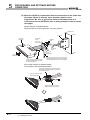
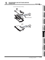
While pressing the installation lever located at the bottom of the module, fully insert the module fixing
projection into the fixing hole in the base unit and press the module using the hole as a fulcrum.
Incorrect module mounting may cause a malfunction, failure, or drop of the module.
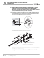
In an environment of frequent vibrations, secure the module with screws.
The screws must be tightened within the specified torque range. If the screw is too loose, it may
cause a drop, short circuit, or malfunction. Excessive tightening may damage the screw and/or the
module, resulting in a drop, short circuit or malfunction.
Be sure to shut off all phases of the external power supply used by the system before mounting or
removing the module.
Failure to do so may cause damage to the product.
Do not directly touch any conductive part or electronic part of the module.
Doing so may cause a malfunction or failure of the module.
[WIRING PRECAUTIONS]
DANGER
Correctly wire cables to the module after checking the terminal layout.
Be careful to prevent foreign matter such as dust or wire chips from entering the module.
Failure to do may cause a fire, failure or malfunction.
A-2
[STARTUP/MAINTENANCE PRECAUTIONS]
DANGER
Be sure to shut off all phases of the external power supply used by the system before cleaning or
retightening module fixing screw.
Failure to do so may cause an electric shock.
CAUTION
Do not or remodel each of the modules.
Doing so may cause failure, malfunctions, personal injuries and/or a fire.
Be sure to shut off all phases of the external power supply used by the system before mounting or
removing the module.
Not doing so may result in a failure or malfunction of the module.
Do not mount/remove the module onto/from the base unit more than 50 times (IEC 61131-2compliant), after the first use of the product.
Doing so may cause malfunctions.
Before starting test operation, set the parameter speed limit value slow, and prepare so that
operation can be stopped immediately in case of hazardous situation.
Before handling the module, touch a grounded metal object to discharge the static electricity from
the human body.
Not doing so may result in a failure or malfunction of the module.
[DISPOSAL PRECAUTIONS]
CAUTION
When disposing of this product, treat it as industrial waste.
A-3
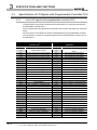
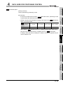
REVISIONS
* The manual number is given on the bottom left of the back cover.
Print date
*Manual number
Revision
Jun., 2007
SH(NA)-080683ENG-A First edition
Jan., 2008
SH(NA)-080683ENG-B About the Generic Terms and Abbreviations, Section 2.3 to 2.6, Section 6.2.1,
Correction
Section 6.2.2 Appendix 1
This manual confers no industrial property rights or any rights of any other kind, nor does it confer any licenses. Mitsubishi
Electric Corporation cannot be held responsible for any problems involving industrial property rights which may occur as a
2007 MITSUBISHI ELECTRIC CORPORATION
A-4
INTRODUCTION
Thank you for purchasing the Mitsubishi programmable controller MELSEC-Q series.
Before using the product, please read this manual carefully to develop full familiarity with the functions and
performance of the Q series programmable controller to ensure correct use.
CONTENTS
SAFETY PRECAUTIONS•••••••••••••••••••••••••••••••••••••••••••••••••••••••••••••••••••••••••••••••••••••••••••••••••••••• A - 1
REVISIONS••••••••••••••••••••••••••••••••••••••••••••••••••••••••••••••••••••••••••••••••••••••••••••••••••••••••••••••••••••••• A - 4
INTRODUCTION •••••••••••••••••••••••••••••••••••••••••••••••••••••••••••••••••••••••••••••••••••••••••••••••••••••••••••••••• A - 5
CONTENTS••••••••••••••••••••••••••••••••••••••••••••••••••••••••••••••••••••••••••••••••••••••••••••••••••••••••••••••••••••••• A - 5
HOW TO READ THIS MANUAL ••••••••••••••••••••••••••••••••••••••••••••••••••••••••••••••••••••••••••••••••••••••••••••• A - 10
Compliance with the EMC and Low Voltage Directives ••••••••••••••••••••••••••••••••••••••••••••••••••••••••••••••••• A - 10
GENERIC TERMS AND ABBREVIATIONS ••••••••••••••••••••••••••••••••••••••••••••••••••••••••••••••••••••••••••••••• A - 11
PACKING LIST•••••••••••••••••••••••••••••••••••••••••••••••••••••••••••••••••••••••••••••••••••••••••••••••••••••••••••••••••• A - 11
PART 1 PRODUCT SPECIFICATIONS AND HANDLING 1
CHAPTER1 PRODUCT OUTLINE
1 - 1 to 1 - 13
1.1
Features of QD72P3C3•••••••••••••••••••••••••••••••••••••••••••••••••••••••••••••••••••••••••••••••••••••••••••• 1 - 1
1.2
Outline of Positioning Control and Count Operation ••••••••••••••••••••••••••••••••••••••••••••••••••••••••• 1 - 3
1.2.1
1.2.2
1.2.3
1.2.4
1.3
Mechanism of positioning control •••••••••••••••••••••••••••••••••••••••••••••••••••••••••••••••••••••••••• 1 - 3
Design outline of positioning control system ••••••••••••••••••••••••••••••••••••••••••••••••••••••••••••• 1 - 5
Design outline of counter function ••••••••••••••••••••••••••••••••••••••••••••••••••••••••••••••••••••••••• 1 - 8
Communicating signals between QD72P3C3 and each module••••••••••••••••••••••••••••••••••••• 1 - 9
Basic Operation of Positioning Control ••••••••••••••••••••••••••••••••••••••••••••••••••••••••••••••••••••••• 1 - 12
1.3.1
1.3.2
Outline of control start •••••••••••••••••••••••••••••••••••••••••••••••••••••••••••••••••••••••••••••••••••••• 1 - 12
Outline of control stop •••••••••••••••••••••••••••••••••••••••••••••••••••••••••••••••••••••••••••••••••••••• 1 - 13
CHAPTER2 SYSTEM CONFIGURATION
2 - 1 to 2 - 9
2.1
General Image of System ••••••••••••••••••••••••••••••••••••••••••••••••••••••••••••••••••••••••••••••••••••••••• 2 - 1
2.2
Component List•••••••••••••••••••••••••••••••••••••••••••••••••••••••••••••••••••••••••••••••••••••••••••••••••••••• 2 - 2
2.3
Applicable System •••••••••••••••••••••••••••••••••••••••••••••••••••••••••••••••••••••••••••••••••••••••••••••••••• 2 - 3
2.4
About Use of the QD72P3C3 with the Q12PRH/Q25PRHCPU•••••••••••••••••••••••••••••••••••••••••••• 2 - 6
2.5
About Use of the QD72P3C3 with the MELSECNET/H Remote I/O Station •••••••••••••••••••••••••••• 2 - 7
2.6
How to Check the Function Version/Software Version •••••••••••••••••••••••••••••••••••••••••••••••••••••• 2 - 8
CHAPTER3 SPECIFICATIONS AND FUNCTIONS
3 - 1 to 3 - 19
3.1
Performance Specifications••••••••••••••••••••••••••••••••••••••••••••••••••••••••••••••••••••••••••••••••••••••• 3 - 1
3.2
Function List ••••••••••••••••••••••••••••••••••••••••••••••••••••••••••••••••••••••••••••••••••••••••••••••••••••••••• 3 - 2
3.3
Specifications of I/O Signals with Programmable Controller CPU••••••••••••••••••••••••••••••••••••••••• 3 - 4
A-5
3.3.1
3.3.2
3.3.3
List of I/O signals with programmable controller CPU••••••••••••••••••••••••••••••••••••••••••••••••••3 - 4
Details of input signal (QD72P3C3 programmable controller CPU) ••••••••••••••••••••••••••••••••3 - 6
Details of output signals (programmable controller CPU QD72P3C3) •••••••••••••••••••••••••••••3 - 8
3.4
List of Buffer Memory Addresses •••••••••••••••••••••••••••••••••••••••••••••••••••••••••••••••••••••••••••••• 3 - 10
3.5
Specifications of I/O Interfaces with External Device •••••••••••••••••••••••••••••••••••••••••••••••••••••• 3 - 12
3.5.1
3.5.2
3.5.3
3.5.4
Electrical specifications of I/O signals ••••••••••••••••••••••••••••••••••••••••••••••••••••••••••••••••••• 3 - 12
Signal layout for external device connector •••••••••••••••••••••••••••••••••••••••••••••••••••••••••••• 3 - 16
List of I/O signal details •••••••••••••••••••••••••••••••••••••••••••••••••••••••••••••••••••••••••••••••••••• 3 - 17
Internal circuit of I/O interface••••••••••••••••••••••••••••••••••••••••••••••••••••••••••••••••••••••••••••• 3 - 18
CHAPTER4 DATA USED FOR POSITIONING CONTROL
4.1
4 - 1 to 4 - 31
Data Types •••••••••••••••••••••••••••••••••••••••••••••••••••••••••••••••••••••••••••••••••••••••••••••••••••••••••••4 - 1
4.1.1
4.1.2
4.1.3
4.1.4
4.1.5
4.1.6
Parameters and data required for control ••••••••••••••••••••••••••••••••••••••••••••••••••••••••••••••••4 - 1
Parameter setting items••••••••••••••••••••••••••••••••••••••••••••••••••••••••••••••••••••••••••••••••••••••4 - 3
JOG data setting items •••••••••••••••••••••••••••••••••••••••••••••••••••••••••••••••••••••••••••••••••••••••4 - 5
Positioning data setting items•••••••••••••••••••••••••••••••••••••••••••••••••••••••••••••••••••••••••••••••4 - 5
Types and functions of monitor data ••••••••••••••••••••••••••••••••••••••••••••••••••••••••••••••••••••••4 - 6
Types and functions of control data •••••••••••••••••••••••••••••••••••••••••••••••••••••••••••••••••••••••4 - 6
4.2
Parameter List •••••••••••••••••••••••••••••••••••••••••••••••••••••••••••••••••••••••••••••••••••••••••••••••••••••••4 - 7
4.3
JOG Data List•••••••••••••••••••••••••••••••••••••••••••••••••••••••••••••••••••••••••••••••••••••••••••••••••••••• 4 - 21
4.4
Positioning Data List•••••••••••••••••••••••••••••••••••••••••••••••••••••••••••••••••••••••••••••••••••••••••••••• 4 - 23
4.5
Monitor Data List •••••••••••••••••••••••••••••••••••••••••••••••••••••••••••••••••••••••••••••••••••••••••••••••••• 4 - 28
4.6
Control Data List •••••••••••••••••••••••••••••••••••••••••••••••••••••••••••••••••••••••••••••••••••••••••••••••••• 4 - 30
4.6.1
Axis control data••••••••••••••••••••••••••••••••••••••••••••••••••••••••••••••••••••••••••••••••••••••••••••• 4 - 30
CHAPTER5 PROCEDURES AND SETTINGS BEFORE OPERATION
5 - 1 to 5 - 21
5.1
Handling Precautions ••••••••••••••••••••••••••••••••••••••••••••••••••••••••••••••••••••••••••••••••••••••••••••••5 - 1
5.2
Procedures Before Operation ••••••••••••••••••••••••••••••••••••••••••••••••••••••••••••••••••••••••••••••••••••5 - 3
5.3
Part Names ••••••••••••••••••••••••••••••••••••••••••••••••••••••••••••••••••••••••••••••••••••••••••••••••••••••••••5 - 4
5.4
Wiring •••••••••••••••••••••••••••••••••••••••••••••••••••••••••••••••••••••••••••••••••••••••••••••••••••••••••••••••••5 - 7
5.4.1
5.5
Wiring precautions ••••••••••••••••••••••••••••••••••••••••••••••••••••••••••••••••••••••••••••••••••••••••••••5 - 7
Wiring Check••••••••••••••••••••••••••••••••••••••••••••••••••••••••••••••••••••••••••••••••••••••••••••••••••••••• 5 - 12
5.5.1
Check items at wiring completion •••••••••••••••••••••••••••••••••••••••••••••••••••••••••••••••••••••••• 5 - 12
5.6
Intelligent Function Module Switch Setting••••••••••••••••••••••••••••••••••••••••••••••••••••••••••••••••••• 5 - 14
5.7
Simple Reciprocating Operation ••••••••••••••••••••••••••••••••••••••••••••••••••••••••••••••••••••••••••••••• 5 - 18
CHAPTER6 UTILITY PACKAGE (GX Configurator-PT)
6 - 1 to 6 - 22
6.1
Utility Package Functions •••••••••••••••••••••••••••••••••••••••••••••••••••••••••••••••••••••••••••••••••••••••••6 - 1
6.2
Installing and Uninstalling the Utility Package•••••••••••••••••••••••••••••••••••••••••••••••••••••••••••••••••6 - 2
6.2.1
6.2.2
6.3
Utility Package Operation •••••••••••••••••••••••••••••••••••••••••••••••••••••••••••••••••••••••••••••••••••••••••6 - 6
6.3.1
A-6
Handling precautions •••••••••••••••••••••••••••••••••••••••••••••••••••••••••••••••••••••••••••••••••••••••••6 - 2
Operating environment •••••••••••••••••••••••••••••••••••••••••••••••••••••••••••••••••••••••••••••••••••••••6 - 4
Common utility package operations •••••••••••••••••••••••••••••••••••••••••••••••••••••••••••••••••••••••6 - 6
6.3.2
6.3.3
Operation overview ••••••••••••••••••••••••••••••••••••••••••••••••••••••••••••••••••••••••••••••••••••••••••• 6 - 8
Starting the Intelligent function module utility •••••••••••••••••••••••••••••••••••••••••••••••••••••••••• 6 - 10
6.4
Initial Setting ••••••••••••••••••••••••••••••••••••••••••••••••••••••••••••••••••••••••••••••••••••••••••••••••••••••• 6 - 12
6.5
Auto Refresh Setting ••••••••••••••••••••••••••••••••••••••••••••••••••••••••••••••••••••••••••••••••••••••••••••• 6 - 15
6.6
Monitoring/Test •••••••••••••••••••••••••••••••••••••••••••••••••••••••••••••••••••••••••••••••••••••••••••••••••••• 6 - 17
6.6.1
6.6.2
Monitoring/Test screen ••••••••••••••••••••••••••••••••••••••••••••••••••••••••••••••••••••••••••••••••••••• 6 - 17
ACC/DEC time calculation function screen •••••••••••••••••••••••••••••••••••••••••••••••••••••••••••• 6 - 21
CHAPTER7 SEQUENCE PROGRAM USED FOR POSITIONING
CONTROL
7 - 1 to 7 - 31
7.1
Precautions for Creating Program ••••••••••••••••••••••••••••••••••••••••••••••••••••••••••••••••••••••••••••••• 7 - 1
7.2
List of Devices Used ••••••••••••••••••••••••••••••••••••••••••••••••••••••••••••••••••••••••••••••••••••••••••••••• 7 - 4
7.3
Creating a Program••••••••••••••••••••••••••••••••••••••••••••••••••••••••••••••••••••••••••••••••••••••••••••••••• 7 - 9
7.3.1
7.3.2
General configuration of program •••••••••••••••••••••••••••••••••••••••••••••••••••••••••••••••••••••••••• 7 - 9
Positioning control operation program •••••••••••••••••••••••••••••••••••••••••••••••••••••••••••••••••• 7 - 10
7.4
Positioning Control Program Examples •••••••••••••••••••••••••••••••••••••••••••••••••••••••••••••••••••••• 7 - 13
7.5
Program Details ••••••••••••••••••••••••••••••••••••••••••••••••••••••••••••••••••••••••••••••••••••••••••••••••••• 7 - 23
7.5.1
7.5.2
7.5.3
7.5.4
7.6
Initialization program ••••••••••••••••••••••••••••••••••••••••••••••••••••••••••••••••••••••••••••••••••••••• 7 - 23
Start method setting program ••••••••••••••••••••••••••••••••••••••••••••••••••••••••••••••••••••••••••••• 7 - 24
Start program •••••••••••••••••••••••••••••••••••••••••••••••••••••••••••••••••••••••••••••••••••••••••••••••• 7 - 25
Auxiliary program•••••••••••••••••••••••••••••••••••••••••••••••••••••••••••••••••••••••••••••••••••••••••••• 7 - 30
Program Example when the Coincidence Detection Interrupt Function is Used ••••••••••••••••••••• 7 - 31
PART 2 CONTROL DETAILS AND SETTING 1
CHAPTER8 OPR CONTROL
8.1
Outline of OPR Control •••••••••••••••••••••••••••••••••••••••••••••••••••••••••••••••••••••••••••••••••••••••••••• 8 - 1
8.1.1
8.2
Outline of the machine OPR operation•••••••••••••••••••••••••••••••••••••••••••••••••••••••••••••••••••• 8 - 2
OPR method for machine OPR control ••••••••••••••••••••••••••••••••••••••••••••••••••••••••••••••••••• 8 - 4
OPR method (1): Near-point dog method •••••••••••••••••••••••••••••••••••••••••••••••••••••••••••••••• 8 - 5
OPR method (2): Stopper 3 ••••••••••••••••••••••••••••••••••••••••••••••••••••••••••••••••••••••••••••••••• 8 - 8
Fast OPR Control ••••••••••••••••••••••••••••••••••••••••••••••••••••••••••••••••••••••••••••••••••••••••••••••••• 8 - 10
8.3.1
8.4
Two types of OPR control ••••••••••••••••••••••••••••••••••••••••••••••••••••••••••••••••••••••••••••••••••• 8 - 1
Machine OPR Control•••••••••••••••••••••••••••••••••••••••••••••••••••••••••••••••••••••••••••••••••••••••••••••• 8 - 2
8.2.1
8.2.2
8.2.3
8.2.4
8.3
Outline of the fast OPR control operation •••••••••••••••••••••••••••••••••••••••••••••••••••••••••••••• 8 - 10
Count Value Selection Function at OPR ••••••••••••••••••••••••••••••••••••••••••••••••••••••••••••••••••••• 8 - 12
CHAPTER9 POSITIONING CONTROL
9.1
9 - 1 to 9 - 15
Outline of Positioning Control••••••••••••••••••••••••••••••••••••••••••••••••••••••••••••••••••••••••••••••••••••• 9 - 1
9.1.1
9.1.2
9.1.3
9.1.4
9.2
8 - 1 to 8 - 12
Data required for positioning control••••••••••••••••••••••••••••••••••••••••••••••••••••••••••••••••••••••• 9 - 1
Positioning control operation patterns••••••••••••••••••••••••••••••••••••••••••••••••••••••••••••••••••••• 9 - 2
Specifying the positioning address •••••••••••••••••••••••••••••••••••••••••••••••••••••••••••••••••••••••• 9 - 4
Checking the current value •••••••••••••••••••••••••••••••••••••••••••••••••••••••••••••••••••••••••••••••••• 9 - 5
Positioning Data Setting ••••••••••••••••••••••••••••••••••••••••••••••••••••••••••••••••••••••••••••••••••••••••••• 9 - 7
A-7
9.2.1
9.2.2
9.2.3
9.2.4
9.3
Relation between each control and positioning data •••••••••••••••••••••••••••••••••••••••••••••••••••9 - 7
1-axis linear control •••••••••••••••••••••••••••••••••••••••••••••••••••••••••••••••••••••••••••••••••••••••••••9 - 8
Speed control •••••••••••••••••••••••••••••••••••••••••••••••••••••••••••••••••••••••••••••••••••••••••••••••• 9 - 10
Current value change••••••••••••••••••••••••••••••••••••••••••••••••••••••••••••••••••••••••••••••••••••••• 9 - 13
Multiple axes concurrent start control ••••••••••••••••••••••••••••••••••••••••••••••••••••••••••••••••••••••••• 9 - 15
CHAPTER10 JOG OPERATION
10 - 1 to 10 - 7
10.1
Outline of JOG Operation ••••••••••••••••••••••••••••••••••••••••••••••••••••••••••••••••••••••••••••••••••••••• 10 - 1
10.2
JOG Operation Execution Procedure ••••••••••••••••••••••••••••••••••••••••••••••••••••••••••••••••••••••••• 10 - 4
10.3
JOG Operation Example •••••••••••••••••••••••••••••••••••••••••••••••••••••••••••••••••••••••••••••••••••••••• 10 - 5
CHAPTER11 AUXILIARY FUNCTION
11 - 1 to 11 - 16
11.1
Outline of the Auxiliary Function ••••••••••••••••••••••••••••••••••••••••••••••••••••••••••••••••••••••••••••••• 11 - 1
11.2
Speed Limit Function••••••••••••••••••••••••••••••••••••••••••••••••••••••••••••••••••••••••••••••••••••••••••••• 11 - 2
11.3
Speed Change Function••••••••••••••••••••••••••••••••••••••••••••••••••••••••••••••••••••••••••••••••••••••••• 11 - 3
11.4
Software Stroke Limit Function••••••••••••••••••••••••••••••••••••••••••••••••••••••••••••••••••••••••••••••••• 11 - 6
11.5
Hardware Stroke Limit Function•••••••••••••••••••••••••••••••••••••••••••••••••••••••••••••••••••••••••••••••• 11 - 9
11.6
ACC/DEC Process Function •••••••••••••••••••••••••••••••••••••••••••••••••••••••••••••••••••••••••••••••••••11 - 11
11.6.1
Calculating the actual ACC/DEC time••••••••••••••••••••••••••••••••••••••••••••••••••••••••••••••••••11 - 13
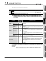
CHAPTER12 COUNTER FUNCTION
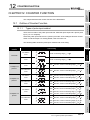
12.1
12 - 1 to 12 - 14
Outline of Counter Function••••••••••••••••••••••••••••••••••••••••••••••••••••••••••••••••••••••••••••••••••••• 12 - 1
12.1.1
12.1.2
12.1.3
Types of pulse input method •••••••••••••••••••••••••••••••••••••••••••••••••••••••••••••••••••••••••••••• 12 - 1
Reading count values •••••••••••••••••••••••••••••••••••••••••••••••••••••••••••••••••••••••••••••••••••••• 12 - 2
Selecting counter format ••••••••••••••••••••••••••••••••••••••••••••••••••••••••••••••••••••••••••••••••••• 12 - 2
12.2
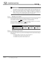
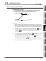
Linear Counter Function ••••••••••••••••••••••••••••••••••••••••••••••••••••••••••••••••••••••••••••••••••••••••• 12 - 3
12.3
Ring Counter Function ••••••••••••••••••••••••••••••••••••••••••••••••••••••••••••••••••••••••••••••••••••••••••• 12 - 4
12.4
Count Enable Function••••••••••••••••••••••••••••••••••••••••••••••••••••••••••••••••••••••••••••••••••••••••••• 12 - 6
12.5
Coincidence Detection Function ••••••••••••••••••••••••••••••••••••••••••••••••••••••••••••••••••••••••••••••• 12 - 7
12.6
Preset Function•••••••••••••••••••••••••••••••••••••••••••••••••••••••••••••••••••••••••••••••••••••••••••••••••••12 - 11
12.7
Current Feed Value, Count Value Simultaneous Change Function••••••••••••••••••••••••••••••••••••12 - 12
CHAPTER13 COMMON FUNCTION
13 - 1 to 13 - 4
13.1
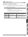
Outline of Common Function ••••••••••••••••••••••••••••••••••••••••••••••••••••••••••••••••••••••••••••••••••• 13 - 1
13.2
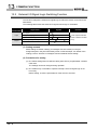
External I/O Signal Logic Switching Function ••••••••••••••••••••••••••••••••••••••••••••••••••••••••••••••• 13 - 2
13.3
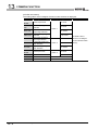
External I/O Signal Monitor Function•••••••••••••••••••••••••••••••••••••••••••••••••••••••••••••••••••••••••• 13 - 3
CHAPTER14 DEDICATED INSTRUCTIONS
14 - 1 to 14 - 15
14.1
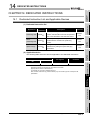
Dedicated Instruction List and Applicable Devices ••••••••••••••••••••••••••••••••••••••••••••••••••••••••• 14 - 1
14.2
Interlock for Dedicated Instruction Execution•••••••••••••••••••••••••••••••••••••••••••••••••••••••••••••••• 14 - 2
A-8
14.3
PSTRT1, PSTRT2, PSTRT3 ••••••••••••••••••••••••••••••••••••••••••••••••••••••••••••••••••••••••••••••••••• 14 - 3
14.4
DSTRT1, DSTRT2, DSTRT3 ••••••••••••••••••••••••••••••••••••••••••••••••••••••••••••••••••••••••••••••••••• 14 - 8
14.5
SPCHG1, SPCHG2, SPCHG3 ••••••••••••••••••••••••••••••••••••••••••••••••••••••••••••••••••••••••••••••••14 - 12
CHAPTER15 TROUBLESHOOTING
15.1
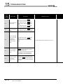
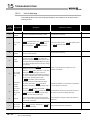
Troubleshooting Flow •••••••••••••••••••••••••••••••••••••••••••••••••••••••••••••••••••••••••••••••••••••••••••• 15 - 1
15.1.1
15.1.2
15.1.3
15.1.4
15.1.5
15.1.6
15.2
15 - 1 to 15 - 22
When the RUN LED turns OFF••••••••••••••••••••••••••••••••••••••••••••••••••••••••••••••••••••••••••• 15 - 2
When the ERR.LED turns ON •••••••••••••••••••••••••••••••••••••••••••••••••••••••••••••••••••••••••••• 15 - 2
When the AX LED flashes after the ERR.LED flashes••••••••••••••••••••••••••••••••••••••••••••••• 15 - 2
When the axis/CH warning occurrence signal (X4 to X6) turns ON ••••••••••••••••••••••••••••••• 15 - 2
When the count operation is not executed, or not executed normally •••••••••••••••••••••••••••• 15 - 3
When the coincidence detection interrupt does not occur••••••••••••••••••••••••••••••••••••••••••• 15 - 4
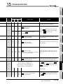
Error and Warning Descriptions•••••••••••••••••••••••••••••••••••••••••••••••••••••••••••••••••••••••••••••••• 15 - 5
15.2.1
15.2.2
Error code list •••••••••••••••••••••••••••••••••••••••••••••••••••••••••••••••••••••••••••••••••••••••••••••••• 15 - 7
List of warnings •••••••••••••••••••••••••••••••••••••••••••••••••••••••••••••••••••••••••••••••••••••••••••••15 - 19
15.3
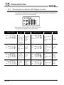
Checking Errors with the LED Display Function •••••••••••••••••••••••••••••••••••••••••••••••••••••••••••15 - 21
15.4
Checking Error Description Using System Monitor of GX Developer••••••••••••••••••••••••••••••••••15 - 22
APPENDICES
Appendix 1
App - 1 to App - 20
External Dimensions •••••••••••••••••••••••••••••••••••••••••••••••••••••••••••••••••••••••••••••••••• App - 1
Appendix 2
Operation Timing and Processing Time in Each Control••••••••••••••••••••••••••••••••••••••• App - 2
Appendix 3
Connection Examples with Servo Amplifiers Manufactured by Mitsubishi Electric
Corporation•••••••••••••••••••••••••••••••••••••••••••••••••••••••••••••••••••••••••••••••••••••••••••••• App - 7
Appendix 4
Connection Examples with Stepping Motors Manufactured by ORIENTAL
MOTOR CO., LTD. •••••••••••••••••••••••••••••••••••••••••••••••••••••••••••••••••••••••••••••••••••App - 11
Appendix 5
Connection Examples with Servo Amplifiers Manufactured by Matsushita
Electric Industrial Co., Ltd. ••••••••••••••••••••••••••••••••••••••••••••••••••••••••••••••••••••••••••App - 13
Appendix 6
Connection Examples with Servo Amplifiers Manufactured by YASUKAWA ELECTRIC
CORPORATION ••••••••••••••••••••••••••••••••••••••••••••••••••••••••••••••••••••••••••••••••••••••App - 15
Appendix 7
Connection Examples with Servo Amplifiers Manufactured by SANYO
DENKI CO., LTD. •••••••••••••••••••••••••••••••••••••••••••••••••••••••••••••••••••••••••••••••••••••App - 16
Appendix 8
Comparison with QD70P type positioning module •••••••••••••••••••••••••••••••••••••••••••••App - 17
Appendix 9
List of Buffer Memory Addresses ••••••••••••••••••••••••••••••••••••••••••••••••••••••••••••••••••App - 20
INDEX
Index - 1 to Index - 3
A-9
HOW TO READ THIS MANUAL
(1) The symbols used in this manual are shown below.
Pr.*
Indicates parameter item.
JOG.*
Indicates JOG data item.
Da.*
Indicates positioning data item.
Md.*
Indicates monitor data item.
Cd.* Indicates control data item.
(Serial No. is displayed at the *.)
(2) Numeric values used in this manual
The buffer memory addresses, error codes and warning codes are represented in
decimal.
The X/Y devices are represented in hexadecimal.
The setting data and monitor data are represented in either decimal or hexadecimal.
The data whose name is ended by "H" are represented in hexadecimal.
(Example) 10......Decimal, 10H......Hexadecimal
Compliance with the EMC and Low Voltage Directives
When incorporating the Mitsubishi programmable controller into other machinery or
system and ensuring compliance with the EMC and Low Voltage Directives, refer to
Chapter 3 "EMC and Low Voltage Directive" in the User's Manual (Hardware) of the CPU
module. The CE logo is printed on the rating plate of the programmable controller,
indicating compliance with the EMC and Low Voltage Directives.
To conform this product to the EMC and Low Voltage Directives, refer to "CHAPTER 5
PROCEDURES AND SETTINGS BEFORE OPERATION (Section 5.4.1 Wiring
precautions)".
A - 10
GENERIC TERMS AND ABBREVIATIONS
Unless otherwise specified, this manual uses the following generic terms and
abbreviations.
Generic term and
Description
abbreviation
Programmable
controller CPU
QD72P3C3
Generic term for the programmable controller CPU to which the QD72P3C3 can be mounted.
Abbreviation for the QD72P3C3 type positioning module with built-in counter function
Generic term for IBM-PC/AT-compatible personal computer in which "GX Configurator-PT" and
Peripheral
"GX Developer" below have been installed.
GX Configurator-PT
Abbreviation for utility package GX Configurator-PT (SW1D5C-QPTU-E) for the QD72P3C3 type
positioning module
Generic product name for the SWnD5C-GPPW-E, SWnD5C-GPPW-EA, SWnD5C-GPPW-EV and
GX Developer
SWnD5C-GPPW-EVA. ("n" is 4 or greater.)
"-A" and "-V" denote volume license product and upgraded product respectively.
Personal computer
Workpiece
Generic term for IBM-PC/AT-compatible personal computer
Generic term for mobile object and controlled object such as workpiece and industrial tool
Generic term for the following:
Windows Vista
Microsoft
Windows Vista
Home Basic Operating System,
Microsoft
Windows Vista
Home Premium Operating System,
Microsoft
Windows Vista
Business Operating System,
Microsoft
Windows Vista
Ultimate Operating System,
Microsoft Windows Vista Enterprise Operating System
Generic term for the following:
Windows
XP
Microsoft
Windows
XP Professional Operating System,
Microsoft
Windows
XP Home Edition Operating System
PACKING LIST
The following are included in the package.
Model
QD72P3C3
Product name
QD72P3C3 type positioning module with built-in counter function
Quantity
1
SW1D5C-QPTU-E
GX Configurator-PT Version 1 (single license product) (CD-ROM)
1
SW1D5C-QPTU-AE
GX Configurator-PT Version 1 (volume license product) (CD-ROM)
1
A - 11
Memo
A - 12
PART 1 PRODUCT
SPECIFICATIONS
AND HANDLING
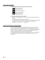
PART 1 consists for the following purposes (1) to (4).
(1) To understand the outline of positioning control, and the QD72P3C3 specifications and functions
(2) To perform actual work such as installation and wiring
(3) To set parameters and data required for positioning control
(4) To create a sequence program required for positioning control
For details of each control, refer to "PART 2".
CHAPTER1PRODUCT OUTLINE . . . . . . . . . . . . . . . . . . . . . . . . . . . . . . . . . . . . 1 - 1 to 1 - 13
CHAPTER2SYSTEM CONFIGURATION . . . . . . . . . . . . . . . . . . . . . . . . . . . . . . . 2 - 1 to 2 - 9
CHAPTER3SPECIFICATIONS AND FUNCTIONS . . . . . . . . . . . . . . . . . . . . . . . 3 - 1 to 3 - 19
CHAPTER4DATA USED FOR POSITIONING CONTROL . . . . . . . . . . . . . . . . . 4 - 1 to 4 - 31
CHAPTER5PROCEDURES AND SETTINGS BEFORE OPERATION. . . . . . . . 5 - 1 to 5 - 21
CHAPTER6UTILITY PACKAGE (GX Configurator-PT). . . . . . . . . . . . . . . . . . . . 6 - 1 to 6 - 22
CHAPTER7SEQUENCE PROGRAM USED FOR POSITIONING CONTROL . . .7 - 1 to 7 -31
Memo
1
PRODUCT OUTLINE
This User's Manual describes the specifications, handling, and programming methods for
the type QD72P3C3 positioning module with built-in counter function used together with
the MELSEC-Q series CPU module.
When applying any of the program examples introduced in this manual to the actual
system, verify the applicability and confirm that no problem occurs in the system control.
Features of QD72P3C3
(1) Space saving
The QD72P3C3 provides 3-axes of positioning control and 3-channels of counter
function per slot.
(2) Positioning control
SPECIFICATIONS
AND FUNCTIONS
3
The following describes the features of the QD72P3C3.
(b) The pulse output mode is selectable.
The pulse output mode can be selected from PULSE/SIGN and CW/CCW.
(c) Easy positioning control with only a few parameter settings is possible.
With only a few parameter settings, such as "Command speed", "ACC/DEC time"
and "Positioning address/movement amount", positioning control can be
performed.
(d) 3-axes concurrent start is possible.
6
UTILITY PACKAGE
(GX Configurator-PT)
(e) Speed change during positioning control is possible by the target speed change
function.
5
PROCEDURES AND
SETTINGS BEFORE
OPERATION
(a) The QD72P3C3 is an open-collector output type module, which can output pulses
at a maximum rate of 100kpps.
DATA USED FOR
POSITIONING
CONTROL
4
(3) Counter function
(a) With this function, a maximum counting speed of 100kpps is possible.
(b) A counting range is from -1073741824 to 1073741823.
(c) The pulse input mode is selectable.
The pulse input mode can be selected from 1 multiple of 2 phases, 2 multiples of
2 phases, 4 multiples of 2 phases, and CW/CCW.
(d) The coincidence detection function is provided.
The coincidence detection point preset at an arbitrary channel is compared to the
current counter value and the result can be checked.
When the current counter value coincides with the preset detection point, an
interrupt program can be started using an interrupt pointer.
7
8
OPR CONTROL
1.1
2
SYSTEM
CONFIGURATION
PRODUCT OUTLINE
SEQUENCE
PROGRAM USED
FOR POSITIONING
CHAPTER1
PRODUCT OUTLINE
1
1.1 Features of QD72P3C3
1-1
1
PRODUCT OUTLINE
(4) Simple settings using the utility package
The utility package (GX Configurator-PT) is sold separately.
The utility package enables to make initial setting and auto refresh setting on the
screen, which lead to load reduction of the sequence programs and simplicity in
checking the setting status and operation status.
1-2
1.1 Features of QD72P3C3
1
PRODUCT OUTLINE
1
1.2.1
PRODUCT OUTLINE
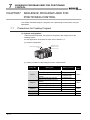
Outline of Positioning Control and Count Operation
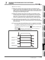
Mechanism of positioning control
Positioning control using the QD72P3C3 is performed using "pulse signals". (The
QD72P3C3 is a module that outputs pulses.)
In a positioning control system using the QD72P3C3, a variety of software and external
devices are used to play their roles as shown below.
The QD72P3C3 realizes complex positioning control by importing and controlling various
signals, parameters, and data with the programmable controller CPU.
3
Stores the created program.
SPECIFICATIONS
AND FUNCTIONS
Outputs the positioning start signal
(Y8 to YA) and axis stop signal
(Y4 to Y6) to the QD72P3C3 according
to the stored program.
Detects such as QD72P3C3 errors.
4
Programmable
controller CPU
DATA USED FOR
POSITIONING
CONTROL
Peripheral
GX Developer/
GX Configurator-PT
Inputs the near-point dog signal and
upper/lower limit signal to the QD72P3C3.
Mechanical system
inputs (switches)
5
PROCEDURES AND
SETTINGS BEFORE
OPERATION
QD72P3C3
positioning module
Stores the parameters and data.
Outputs pulses to the drive unit according to the
commands from the programmable controller CPU.
6
UTILITY PACKAGE
(GX Configurator-PT)
Drive unit
Drives the motor upon reception of
command pulses from the QD72P3C3.
7
SEQUENCE
PROGRAM USED
FOR POSITIONING
Motor
Performs actual operation according
to commands from the drive unit.
8
Workpiece
OPR CONTROL
Using GX Developer, creates
control sequence and conditions
as a sequence program.
Adding in GX Configurator-PT
enables initial setting of
parameters and data.
2
SYSTEM
CONFIGURATION
1.2
1.2 Outline of Positioning Control and Count Operation
1.2.1 Mechanism of positioning control
1-3
1
PRODUCT OUTLINE
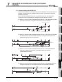
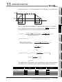
The following describes the operation principle of "position control" and "speed control".
(1) Position control
The total number of pulses required to move the specified distance is obtained in the
following manner.
Specified distance
Total number of pulses required
to move the specified distance
Number of pulses
required for the motor
to rotate once
Movement amount of the
machine (load) side when
the motor rotates once
* The number of pulses required for the motor to rotate once is the
"encoder resolution" described in the motor catalog specification list.
When this total number of pulses is issued from the QD72P3C3 to the drive unit, the
control, for which the workpiece to move the specified distance, can be realized.
The machine side movement amount when one pulse is issued to the drive unit is
called the "movement amount per pulse". This value is the minimum value for the
workpiece to move, and is also the degree of accuracy for electrical positioning
control.
(2) Speed control
Although the above "total number of pulses" is an element required to control the
movement amount, speed must be controlled to perform equal-speed operation.
This "speed" is controlled by the "pulse frequency" output from the QD72P3C3 to the
drive unit.
Pulse frequency
[pps]
Positioning
module
Servo
amplifier
Servomotor
This area indicates the
total number of command
pulses.
A
Encoder
Pulse
encoder
Speed = Pulse frequency
Movement amount = Number of pulses
Feedback pulses
Feedback pulses = Pulses generated by encoder
ta
0.4
td
1.2
(s)
0.4
Movement time t = 2
Figure 1.1 Relationship between position control and speed control
POINT
• The "movement amount per pulse" is the value determined on the
machine side. (Refer to Section 1.2.2.)
• The QD72P3C3 uses the "total number of pulses" to control the position
and the "pulse frequency" to control the speed.
1-4
1.2 Outline of Positioning Control and Count Operation
1.2.1 Mechanism of positioning control
1
PRODUCT OUTLINE
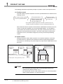
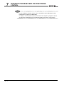
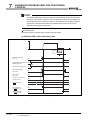
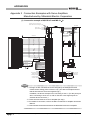
1.2.2
Design outline of positioning control system
The following describes the outline of the operation of positioning control system, using
the QD72P3C3.
PRODUCT OUTLINE
1
(1) Positioning control system using the QD72P3C3
Intelligent
function module
parameter
interface
Buffer
memory/ Reverse run
XY device pulse train
Servo
amplifier
3
M
Interface
Monitor data read
PLG
Feedback pulses
4
Initial setting/Auto refresh setting/Operation monitor
DATA USED FOR
POSITIONING
CONTROL
GX Configurator-PT
Figure 1.2 Outline of the operation of positioning control system using the QD72P3C3
(a) Positioning control operation using the QD72P3C3
1) The QD72P3C3 outputs a pulse train.
When the pulse train is output from the QD72P3C3, the deviation counter of
the drive unit accumulates the input pulses.
The D/A converter converts these accumulated pulses (droop pulses) into DC
analog voltage, which serves as a speed command for the servomotor.
2) The servomotor starts its rotation upon reception of the speed command from
the drive unit.
As the servomotor rotates, the pulse encoder (PLG) attached to the
servomotor generates feedback pulses in proportion to the rotation frequency.
The generated feedback pulses are fed back to the drive unit, and reduce the
droop pulses of the deviation counter.
The deviation counter maintains a certain number of droop pulses so that the
servomotor keeps its rotation.
3) When the QD72P3C3 stops the output of commanded pulse train, the
servomotor decelerates as the droop pulses of the deviation counter decrease
and finally stops when the droop pulse count drops to zero.
That is, the servomotor rotation speed is proportional to the pulse frequency,
while the servomotor rotation angle is proportional to the number of
commanded pulses output from the QD72P3C3.
When the movement amount per pulse is given, the overall movement amount
can be determined in proportion to the number of pulses in the pulse train.
The rotation speed (feed speed) of the servomotor, on the other hand, can be
determined by the pulse frequency.
1.2 Outline of Positioning Control and Count Operation
1.2.2 Design outline of positioning control system
SPECIFICATIONS
AND FUNCTIONS
Read, write, etc.
Speed
command
D/A
convertor
1-5
5
PROCEDURES AND
SETTINGS BEFORE
OPERATION
Program
Deviation
counter
Servo motor
6
UTILITY PACKAGE
(GX Configurator-PT)
Drive unit
Forward run
pulse train
7
SEQUENCE
PROGRAM USED
FOR POSITIONING
Positioning module
QD72P3C3
8
OPR CONTROL
Programmable
controller CPU
SYSTEM
CONFIGURATION
2
1
PRODUCT OUTLINE
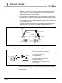
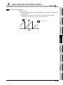
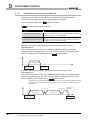
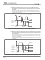
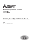
(b) Output pulse from the QD72P3C3
1) As shown in Figure 1.3, the number of pulses in a pulse train is small at the
start, and then the number increases as the servomotor accelerates and its
speed approaches the command speed.
2) The pulse frequency stabilizes once the speed reaches the command speed.
3) To decelerate the servomotor, the QD72P3C3 decreases the number of pulses
in a pulse train before it finally stops the output.
The servomotor actually decelerates and stops its rotation with little delay from
the command pulse stop.
This time difference in deceleration and stop between pulse output from the
QD72P3C3 and the servomotor is called the "stop settling time" and
necessary for ensuring stopping accuracy.
Speed V
Servomotor speed
Droop pulse
amount
Pulse
distribution
Acceleration
Time t
Deceleration
Stop settling
time
Pulse train
Few
pulses
Many pulses
Few
pulses
Figure 1.3 Output pulse from the QD72P3C3
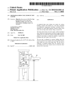
(2) Movement amount and speed in a system using ball screw
A: Movement amount per pulse (mm/pulse)
Vs: Command pulse frequency (pulse/s)
n: Pulse encoder resolution (pulse/rev)
V
L: Feed screw lead (mm/rev)
Workpiece
Feed screw
Pulse encoder(PLG)
R
Table
R: Deceleration ratio
V: Movable section speed (mm/s)
N: Rotation frequency of motor (r/min)
L
K: Position loop gain (1/s )
Servomotor
P0
P
ε: Deviation counter droop pulse amount
P0: OP (pulse)
P: Address (pulse)
Figure 1.4 System using ball screw
In the system shown in Figure 1.4, the movement amount per pulse, command
pulse frequency, and deviation counter droop pulse amount are determined in the
following manner.
1-6
1.2 Outline of Positioning Control and Count Operation
1.2.2 Design outline of positioning control system
PRODUCT OUTLINE
PRODUCT OUTLINE
1
1) Movement amount per pulse
The movement amount per pulse is determined by the feed screw lead,
deceleration ratio, and pulse encoder resolution.
The movement amount, therefore, will be: (Number of pulses output)
(Movement amount per pulse).
n
[ mm/pulse]
2) Command pulse frequency
The command pulse frequency is determined by the movable section speed
and movement amount per pulse.
Vs=
3
V
[ pulse/ s]
A
3) Deviation counter droop pulse amount
The deviation counter droop pulse amount is determined by the command
pulse frequency and position loop gain.
K
[ pulse]
4
DATA USED FOR
POSITIONING
CONTROL
Vs
=
SYSTEM
CONFIGURATION
R
2
SPECIFICATIONS
AND FUNCTIONS
A=
L
PROCEDURES AND
SETTINGS BEFORE
OPERATION
5
UTILITY PACKAGE
(GX Configurator-PT)
6
SEQUENCE
PROGRAM USED
FOR POSITIONING
7
8
OPR CONTROL
1
1.2 Outline of Positioning Control and Count Operation
1.2.2 Design outline of positioning control system
1-7
1
PRODUCT OUTLINE
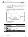
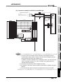
1.2.3
Design outline of counter function
The following describes the outline of the count operation, using the counter function of the
QD72P3C3.
Positioning module
QD72P3C3
Programmable
controller CPU
Drive unit
Servomotor
Forward run pulses
Read/write, etc.
M
Reverse run pulses
Feedback pulses
PLG
Initial setting/
Auto refresh setting
GX Configurator-PT
Buffer memory/
I/O signals
Pulse generator/
encoder
Pulses
Pulse generator/
encoder
Pulses
1) Pulses input to the QD72P3C3 are counted.
Counting pulses can be performed separately from positioning control.
Counting feedback pulses enables positioning control, checking the actual
position at the same time.
The positioning address and count value can be synchronized with the use of
following functions.
Count value selection function at OPR
Refer to
Current feed value, count value
Section 8.4.
Refer to
simultaneous change function
Section 12.7.
2) The status of I/O signals and buffer memory of the QD72P3C3 can be checked with
the sequence program.
The start/stop and preset of count operation can also be performed.
1-8
1.2 Outline of Positioning Control and Count Operation
1.2.3 Design outline of counter function
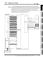
1
PRODUCT OUTLINE
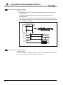
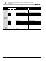
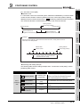
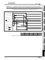
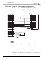
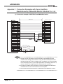
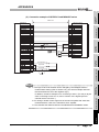
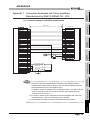
The following shows the outline of the signal communication between the QD72P3C3 and
programmable controller CPU, peripheral (GX Configurator-PT), and drive unit. (A
peripheral is connected to the programmable controller CPU, and communicates signals
with the QD72P3C3 via the programmable controller CPU.)
For details of each I/O signals, refer to CHAPTER 3.
QD72P3C3
Y0
Programmable controller
CPU READY signal
X0
Module READY signal
YC,YE,Y10 Forward run JOG start signal
Reverse run JOG start signal
X10 to X12
External
interface
X8 to XA
BUSY signal
XCto XE
Start complete signal
Pulse train output
Axis stop signal
X1 to X3
Axis/CH error occurrence
signal
Encoder
Near-point dog signal
Axis/CH warning occurrence
signal
Upper/lower limit signal
Axis/CH error reset signal
X14,X18,X1C
X15,X19,X1D
X16,X1A,X1E
Y14 to Y16
Mechanical
system inputs
(switches)
Interface with
programmable
controller CPU
Count value large
5
Count value coincidence
Count value snall
Coincidence signal reset
command
Y18 to Y1A
Preset command
Y1C to Y1E
Count enable command
Peripheral
interface
4
Pulse train input
Y4 to Y6
Y1 to Y3
Deviation counter
clear signal
Positioning complete signal
PROCEDURES AND
SETTINGS BEFORE
OPERATION
Y8 to YA
X4 to X6
Drive unit
Positioning start signal
6
UTILITY PACKAGE
(GX Configurator-PT)
YD,YF,Y11
3
Zero signal
SPECIFICATIONS
AND FUNCTIONS
Programmable
controller CPU
2
SYSTEM
CONFIGURATION
Communicating signals between QD72P3C3 and each module
DATA USED FOR
POSITIONING
CONTROL
1.2.4
PRODUCT OUTLINE
1
Data write/read
7
SEQUENCE
PROGRAM USED
FOR POSITIONING
Monitor data
8
OPR CONTROL
Initial setting/Auto refresh/
Operation monitor
Peripheral
( GX Configurator-PT )
1.2 Outline of Positioning Control and Count Operation
1.2.4 Communicating signals between QD72P3C3 and each module
1-9
1
PRODUCT OUTLINE
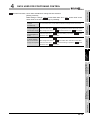
(1) QD72P3C3
Programmable controller CPU
The QD72P3C3 and programmable controller CPU communicate the following data
via the base unit.
Direction
QD72P3C3
Communication
Programmable
controller CPU
Programmable controller CPU
Signals indicate the QD72P3C3 status:
QD72P3C3
Signals related to commands:
•Module READY signal (X0)
•Programmable controller CPU READY
•Axis/CH error occurrence signal (X1 to
signal (Y0)
•Axis/CH error reset signal (Y1 to Y3)
X3)
•Axis/CH warning occurrence signal (X4 •Axis stop signal (Y4 to Y6)
•Positioning start signal (Y8 to YA)
to X6)
•BUSY signal (X8 to XA)
Control signal
•Start complete signal (XC to XE)
•Positioning complete signal (X10 to
•Forward run JOG start signal (YC,YE,
and Y10)
•Reverse run JOG start signal (YD, YF,
and Y11)
X12)
•Count value large (X14, X18, and X1C) •Coincidence signal reset command
•Count value coincidence (X15, X19,
(Y14 to Y16)
•Preset command (Y18 to Y1A)
and X1D)
•Count value small (X16, X1A, and X1E) •Count enable command (Y1C to Y1E)
•Parameter
•Parameter
•JOG data
Data (read/write)
•JOG data
•Positioning data
•Positioning data
•Control data
•Control data
•Monitor data
(2) QCPU
Peripheral (GX Configurator-PT)
The QCPU and peripheral communicates the following data. (For details, refer to
CHAPTER 6.)
Direction
QCPU
Communication
Data
Peripheral
•Auto refresh setting
•Monitor data (QD72P3C3 buffer
-
memory/XY devices)
(3) QD72P3C3
QCPU
•Initial setting
-
Operation monitor
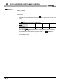
Peripheral
Drive unit
The QD72P3C3 and drive unit communicate the following data via the external device
connector.
Direction
Communication
Control signal
Pulse train
1 - 10
QD72P3C3
Drive unit
Signals related to commands:
Drive unit
QD72P3C3
Signals indicate OP:
•Deviation counter clear signal (CLEAR) •Zero signal (PG0)
•Pulse train output (PULSE F/PULSE R)
1.2 Outline of Positioning Control and Count Operation
1.2.4 Communicating signals between QD72P3C3 and each module
-
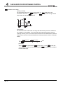
PRODUCT OUTLINE
QD72P3C3
The input signals from the encoder are input to the QD72P3C3 via the external device
connector.
Encoder
•Pulse train input (CH A/CH B)
(5) Mechanical system inputs (switches)
2
QD72P3C3
The input signals from the mechanical system inputs (switches) are input to the
QD72P3C3 via the external device connector.
•Near-point dog signal (DOG)
(switch)
•Upper/lower limit signal (FLS/RLS)
3
SPECIFICATIONS
AND FUNCTIONS
Mechanical system input
SYSTEM
CONFIGURATION
(4) Encoder
PRODUCT OUTLINE
1
DATA USED FOR
POSITIONING
CONTROL
4
PROCEDURES AND
SETTINGS BEFORE
OPERATION
5
UTILITY PACKAGE
(GX Configurator-PT)
6
SEQUENCE
PROGRAM USED
FOR POSITIONING
7
8
OPR CONTROL
1
1.2 Outline of Positioning Control and Count Operation
1.2.4 Communicating signals between QD72P3C3 and each module
1 - 11
1
PRODUCT OUTLINE
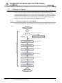
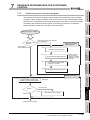
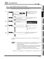
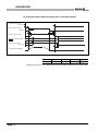
1.3
Basic Operation of Positioning Control
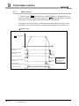
1.3.1
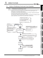
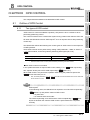
Outline of control start
The following flowchart shows the outline of each control start.
* Assume that module installation and required settings for system configuration have
already been prepared.
Flow of control start
Setting of hardware
Preparation
Control
functions
Installation and connection of module
Positioning control
OPR control
Position control
Speed control
Machine OPR control
Fast OPR control
Current value change
Positioning
parameter
Set the positioning parameters. ( Pr.1 to Pr.9 )
OPR parameter
Counter function
parameter
Positioning data
Control data
Set the OPR parameters.
( Pr.10 to Pr.15 )
Set the counter function parameters.
( Pr.16 to Pr.19 )
Set the positioning
data. ( Da.1 to Da.5 )
Set the start method. ( Cd.5 )
Set the JOG data.
(JOG.1 and JOG.2 )
JOG data
Start signal
Turn ON the positioning start signal
(Y8 to YA) of the QD72P3C3 from the
programmable controller CPU.
Control start
Start
Control end
Stop
1 - 12
JOG operation
1.3 Basic Operation of Positioning Control
1.3.1 Outline of control start
Turn ON the JOG start
signal (YC to Y11) of the
QD72P3C3 from the
programmable controller CPU.
* : Multiple axes simul
taneous start is
possible under
positioning control.
(For details, refer
to Section
Section 9.3.)
9.3.
PRODUCT OUTLINE
1
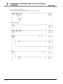
PRODUCT OUTLINE
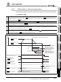
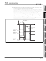
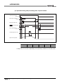
Outline of control stop
A control stops in the following cases:
(1) Each control ended normally.
(4) The axis stop signal (Y4 to Y6) from the programmable controller CPU is
turned ON.
The following table shows the outline of the stop processing performed in the cases
above.
(Except the case (1) where each control ended normally.)
Cause of stop
Programmable controller CPU
error
QD72P3C3 error
The "axis stop signal (Y4 to Y6)"
from the programmable controller
CPU is turned ON.
Stopped
axis
Axis operation
Stop processing
status after
Positioning
JOG
control
operation
stop (
All axes
Axis by
axis
Axis by
axis
Md.4
)
OPR control
Error
Deceleration stop
Error
Deceleration stop
3
SPECIFICATIONS
AND FUNCTIONS
(3) An error occurred in the QD72P3C3.
4
DATA USED FOR
POSITIONING
CONTROL
(2) An error occurred in the programmable controller CPU.
SYSTEM
CONFIGURATION
2
5
Stopped
Deceleration stop
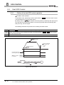
Stop after multiple axes concurrent start under positioning control
The axes started will not stop simultaneously. The stop command (axis stop signal (Y4 to
6
UTILITY PACKAGE
(GX Configurator-PT)
Y6) ON) must be issued to each axis.
PROCEDURES AND
SETTINGS BEFORE
OPERATION
1.3.2
SEQUENCE
PROGRAM USED
FOR POSITIONING
7
8
OPR CONTROL
1
1.3 Basic Operation of Positioning Control
1.3.2 Outline of control stop
1 - 13
2
SYSTEM CONFIGURATION
CHAPTER2
SYSTEM CONFIGURATION
This chapter describes the system configuration of the QD72P3C3.
2.1
General Image of System
The following is the general configuration including the QD72P3C3, programmable
controller CPU, and peripheral, etc.
(Numbers in the figure correspond to the ones in the table in "Section 2.2 Component List"
on the next page.
Peripheral
Personal computer
GX Developer
GX Configurator-PT
RS-232 cable
USB cable
CPU module
1
Main base unit
2
Mechanical system input
(switches)
Power supply 2
module
Positioning module
QD72P3C3
Connection
cable
Near-point dog signal
Upper/lower limit signal
Extension
cable
Drive
unit
Motor
Extension system
Encoder
Remark
*1 For available CPU modules, refer to "Section 2.3 Applicable System".
*2 For available base units and power supply modules, refer to the User's
Manual for the CPU module.
2-1
2.1 General Image of System
2
SYSTEM CONFIGURATION
1
PRODUCT OUTLINE
Component List
A positioning system using the QD72P3C3 consists of the following components.
Remarks
-
2
GX Developer
SW D5C-GPPW-E
For details, refer to the GX Developer Operating Manual and
GX Configurator-PT
SW D5C-QPTU-E
"CHAPTER 6 UTILITY PACKAGE (GX Configurator-PT)".
2
3
Model
QD72P3C3
Personal computer
IBM-PC/AT-compatible (User preparation)
personal computer
For details, refer to the GX Developer Operating Manual.
3
(User preparation)
RS-232 cable
RS-232 cable for connecting CPU module with IBM-PC/AT-
QC30R2
compatible personal computer
SPECIFICATIONS
AND FUNCTIONS
4
For details, refer to the GX Developer Operating Manual.
(User preparation)
5
USB cable
-
USB cable for connecting CPU module with IBM-PC/ATcompatible personal computer
4
For details, refer to the GX Developer Operating Manual.
7
(for connection between
the QD72P3C3 and
drive unit)
-
For details, refer to the manual for the drive unit.
(User preparation)
Cable for connecting the QD72P3C3, drive unit, and encoder
(Install them with reference to the manual for the connected device
5
and Section 3.5.2.)
PROCEDURES AND
SETTINGS BEFORE
OPERATION
Connection cable
(User preparation)
6
UTILITY PACKAGE
(GX Configurator-PT)
-
7
SEQUENCE
PROGRAM USED
FOR POSITIONING
Drive unit
8
OPR CONTROL
6
SYSTEM
CONFIGURATION
No.
Product name
1 Positioning module
DATA USED FOR
POSITIONING
CONTROL
2.2
2.2 Component List
2-2
2
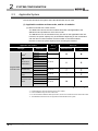
2.3
SYSTEM CONFIGURATION
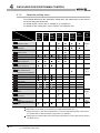
Applicable System
This section describes the system where the QD72P3C3 can be used.
(1) Applicable modules and base units, and No. of modules
(a) When mounted with a CPU module
The table below shows the CPU modules and base units applicable to the
QD72P3C3 and quantities for each CPU model.
The QD72P3C3 can be mounted into any I/O slots on the applicable base unit.
However, the power capacity may be insufficient depending on the combination
with the other mounted modules and the number of mounted modules.
Be sure to check the power capacity when mounting the modules.
Applicable CPU module
CPU type
CPU model
Redundant
Q00JCPU
Q00CPU
Q01CPU
Q02CPU
Q02HCPU
Q06HCPU
Q12HCPU
Q25HCPU
Q12PHCPU
Q25PHCPU
Q12PRHCPU
CPU*4
Q25PRHCPU
Basic model
QCPU*3
High
Performance
model QCPU
Programmable
controller CPU Process CPU
Q02UCPU
Universal model
Q03UDCPU
QCPU
Q04UDHCPU
No. of
modules*1
Base unit*2
Extension base
Main base unit
unit
Up to 8
Up to 24
Up to 64
Up to 64
Up to 53
Up to 36
Up to 64
Q06UDHCPU
: Applicable
*1
*2
*3
*4
2-3
: N/A
Limited within the range of I/O points for the CPU module.
Can be installed to any I/O slot of a base unit.
For the coincidence detection interrupt function, use the CPU module of function version B or later.
The dedicated instructions are not supported in the Redundant CPU system.
2.3 Applicable System
SYSTEM CONFIGURATION
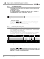
QJ72LP25-25
QJ72LP25G
QJ72LP25GE
QJ72BR15
Up to 64
: Applicable
*1
*2
*3
*4
: N/A
Limited to the slots located within the range of the number of I/O points of the network module.
Can be installed to any I/O slot of a base unit.
The coincidence detection interrupt function is not supported.
The dedicated instructions are not supported.
Remark
The Basic model QCPU cannot configure the MELSECNET/H remote I/O
network.
SYSTEM
CONFIGURATION
No. of modules*1
3
4
5
(2) Support of the multiple CPU system
When using the QD72P3C3 in a multiple CPU system, refer to the QCPU User's
Manual (Multiple CPU System) first.
(a) Intelligent function module parameters
Write intelligent function module parameters to only the control CPU of the
QD72P3C3.
PROCEDURES AND
SETTINGS BEFORE
OPERATION
Mountable network module*3*4
Base unit*2
Extension base
Main base unit of
unit of remote I/O
remote I/O station
station
2
SPECIFICATIONS
AND FUNCTIONS
The QD72P3C3 can be mounted into any I/O slots on the applicable base unit.
However, the power capacity may be insufficient depending on the combination
with the other mounted modules and the number of mounted modules.
Be sure to check the power capacity when mounting the modules.
DATA USED FOR
POSITIONING
CONTROL
(b) Mounting to a MELSECNET/H remote I/O station
The following shows the mountable network modules, No. of mountable modules,
and mountable base unit of the QD72P3C3 module.
PRODUCT OUTLINE
1
UTILITY PACKAGE
(GX Configurator-PT)
6
SEQUENCE
PROGRAM USED
FOR POSITIONING
7
8
OPR CONTROL
2
2.3 Applicable System
2-4
2
SYSTEM CONFIGURATION
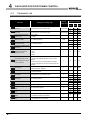
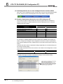
(3) Supported software packages
Relation between the system containing the QD72P3C3 and software package is
shown in the following table.
GX Developer is necessary when using the QD72P3C3.
Software version
GX Developer
GX Configurator-PT
Single CPU
Q00J/Q00/
system
Q01CPU
Multiple CPU
system
Single CPU
Q02/Q02H/Q06H/ system
Q12H/Q25HCPU Multiple CPU
system
Version 7 or later
Version 8 or later
Version 4 or later
Version 6 or later
Single CPU
Q12PH/
system
Q25PHCPU
Multiple CPU
Version 7.10L or later
system
Q12PRH/
Q25PRHCPU
Q02U/Q03UD/
Q04UDH/
Redundant
CPU system
Single CPU
system
Multiple CPU
Q06UDHCPU
system
When mounted to the
MELSECNET/H remote I/O station
2-5
2.3 Applicable System
Version 8.45X or later
Version 8.48A or later
Version 6 or later
Version 1.23Z or later
2
SYSTEM CONFIGURATION
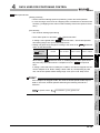
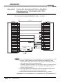
About Use of the QD72P3C3 with the Q12PRH/Q25PRHCPU
Here, use of the QD72P3C3 with the Q12PRH/Q25PRHCPU is explained.
(1) Dedicated instruction
(2) GX Configurator-PT connection
GX Configurator-PT cannot be used when accessing the Q12PRH/Q25PRHCPU via
an intelligent function module on an extension base unit from GX Developer.
Connect a personal computer with a communication path indicated below.
2
3
SPECIFICATIONS
AND FUNCTIONS
1
SYSTEM
CONFIGURATION
2
The dedicated instruction cannnot be used.
Main base unit
DATA USED FOR
POSITIONING
CONTROL
4
Extension base unit
5
1
Direct connection to the CPU
2
Connection through an intelligent function module on the main base unit
(Through Ethernet module, MELSECNET/H module, or CC-Link module)
PROCEDURES AND
SETTINGS BEFORE
OPERATION
(GX Configurator-PT cannot be used.)
UTILITY PACKAGE
(GX Configurator-PT)
6
SEQUENCE
PROGRAM USED
FOR POSITIONING
7
8
OPR CONTROL
2.4
PRODUCT OUTLINE
1
2.4 About Use of the QD72P3C3 with the Q12PRH/Q25PRHCPU
2-6
2
2.5
SYSTEM CONFIGURATION
About Use of the QD72P3C3 with the MELSECNET/H Remote
I/O Station
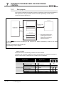
This section describes when using the QD72P3C3 in the MELSECNET/H remote I/O
station.
(1) The number of mountable QD72P3C3 modules when using the
MELSECNET/H remote I/O station
For the number of mountable modules, refer to Section 2.3 (1)(b).
(2) Restrictions on using the MELSECNET/H remote I/O station
(a) When using the QD72P3C3 in the MELSECNET/H remote I/O station, since delay
time due to link scan time occurs, fully assure that the target system is controlled
normally.
Example) Depending on the duration while the positioning complete signal (X10 to
X12) is ON, the ON status cannot be detected due to link scan time delay.
(b) The coincidence detection interrupt function is not supported.
(c) The dedicated instructions are not supported.
2-7
2.5 About Use of the QD72P3C3 with the MELSECNET/H Remote I/O Station
2
SYSTEM CONFIGURATION
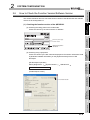
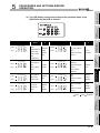
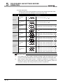
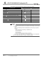
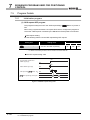
How to Check the Function Version/Software Version
This section describes where to check the function version of the QD72P3C3 and software
version of GX Configurator-PT.
2
SYSTEM
CONFIGURATION
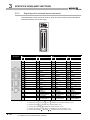
(1) Checking the function version of the QD72P3C3
(a) Checking the rating plate on the module side
Check the version by the last character of "SERIAL".
SPECIFICATIONS
AND FUNCTIONS
3
Serial No. (first 5 digits)
Function version
Relevant regulation
standards
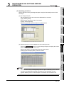
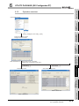
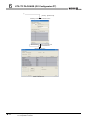
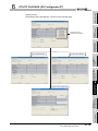
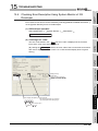
(b) Checking using a peripheral
Check the version by the last character displayed at "Production information" field
of [Module's Detailed Information] on the [System Monitor] screen of GX
Developer.
5
"QD72P3C3"
PROCEDURES AND
SETTINGS BEFORE
OPERATION
[GX Developer operation]
Select [Diagnostics...] [System Monitor...]
DATA USED FOR
POSITIONING
CONTROL
4
Module's Detailed Information .
(GX Developer screen)
UTILITY PACKAGE
(GX Configurator-PT)
6
Function version
SEQUENCE
PROGRAM USED
FOR POSITIONING
7
8
OPR CONTROL
2.6
PRODUCT OUTLINE
1
2.6 How to Check the Function Version/Software Version
2-8
2
SYSTEM CONFIGURATION
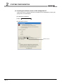
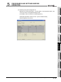
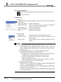
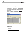
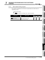
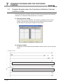
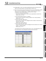
(2) Checking the software version of GX Configurator-PT
Check the version on the [Production information] screen displayed by clicking the
[Help] menu of GX Developer.
[GX Developer operation]
[Help]
Product Information
(GX Developer screen)
Software version
2-9
2.6 How to Check the Function Version/Software Version
3
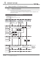
SPECIFICATIONS AND FUNCTIONS
SPECIFICATIONS AND FUNCTIONS
This chapter describes the performance specifications and functions of the QD72P3C3,
and the specifications of the I/O signals to the programmable controller CPU and external
device.
For general specifications of the QD72P3C3, refer to the User's Manual for the CPU
module.
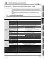
3.1
Performance Specifications
2
SYSTEM
CONFIGURATION
CHAPTER3
PRODUCT OUTLINE
1
Specification
3 axes
None (Artificial linear interpolation by concurrent start is available.)
PTP (Point To Point) control, speed control
pulse
1 data/axis
Positioning control method
Incremental system, absolute system
[Incremental system]
Positioning control range
Positioning
(when using linear counter)
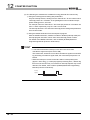
[Absolute system]
1 to 100000pulse/s
Trapezoidal acceleration/deceleration
1 to 5000ms
Start time
Position control,
1-axis start
1ms
speed control
3-axes concurrent start
1ms
Pulse output method
6
Open collector output
Maximum output pulse
100kpps
Maximum connection
2m
distance between drive units
Counting speed (max.)
Number of channels
100kPPS
3 channels
31-bit signed binary
Counting range
7
[Linear counter] -1073741824 to 1073741823
[Ring counter] 0 to 1073741823
External connection system
Peripheral/compatible utility package
Data backup
External device connector
5VDC internal current consumption
Number of occupied I/O points
Weight
*
40-pin connector
0.3mm2
Applicable wire size
(for the A6CON1 and A6CON4), AWG#24 (for the A6CON2)
GX Configurator-PT (sold separately)
None
A6CON1, A6CON2, A6CON4 (sold separately)
0.57A
32 points (I/O assignment: Intelligent 32 points)
0.16kg
For electrical specifications of count input signals, refer to Section 3.5.1 Electrical specifications of
I/O signals.
3.1 Performance Specifications
5
PROCEDURES AND
SETTINGS BEFORE
OPERATION
Speed command
Acceleration/deceleration
ACC/DEC time
function*
-1073741824 to 1073741823 pulse
(when using ring counter) 0 to 1073741823 pulse
processing
Counter
-1073741824 to 1073741823 pulse
UTILITY PACKAGE
(GX Configurator-PT)
control
4
(Set it with GX Configurator-PT or sequence program.)
DATA USED FOR
POSITIONING
CONTROL
Positioning data
3-1
SEQUENCE
PROGRAM USED
FOR POSITIONING
Control unit
8
OPR CONTROL
Item
Number of axes
Interpolation function
Control method
SPECIFICATIONS
AND FUNCTIONS
3
3
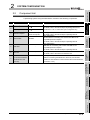
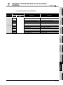
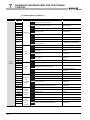
SPECIFICATIONS AND FUNCTIONS
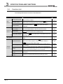
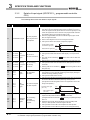
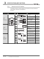
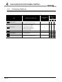
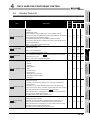
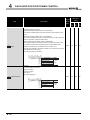
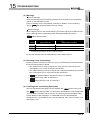
3.2
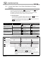
Function List
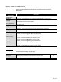
The following table lists the functions of the QD72P3C3.
Control method/function name
Machine OPR control
OPR
control
Positioning
control
Fast OPR control
Description
near-point dog or stopper.
Performs positioning control to the OP address (
Current feed
value) stored in the QD72P3C3 using machine OPR control.
Stores the OP address to "
completed.
Position control (1-axis
Performs positioning control to the position specified to the address
linear control)
set in the positioning data or with the movement amount.
JOG operation
Md.3
Count value" when OPR is
Continuously outputs a pulse corresponding to the
"
Da.4
Command speed" set in positioning data.
Changes the "
Speed limit function
Md.1
Current feed value" to the address set in the
Outputs a pulse to drive unit while the JOG start signal (YC to Y11)
is ON.
Speed change function
Auxiliary
Software stroke limit
function
Section
Section
9.2.2
Section
9.2.3
Section
CHAPTER
10
Pr.4
Speed limit value" during
control, this function limits the command speed to within the
Pr.4
8.3
9.2.4
positioning data.
"
Section
8.4
If the command speed exceeds the "
Section
11.2
Speed limit value" setting range.
Changes the speed during the constant speed of speed control or
JOG operation.
When a command is issued to the outside of the upper limit/lower
limit stroke limit setting range, which are set in the parameters, this
function will not execute operation for that command.
Section
11.3
Section
11.4
Hardware stroke limit
Executes the deceleration stop by the limit switch connected to the
Section
function
ACC/DEC process
QD72P3C3.
11.5
Section
function
3-2
Md.1
function at OPR
Speed control
Section
8.2
Count value selection
Current value change
function
Reference
Mechanically establishes the positioning control start point using a
3.2 Function List
Adjusts the acceleration/deceleration processing of control.
11.6
3
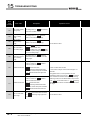
SPECIFICATIONS AND FUNCTIONS
Pr.16
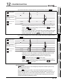
12.2
Ring counter upper limit
Section
value".
Note) When using the ring counter function, the positioning control
12.3
range is from 0 to 1073741823 (pulse).
Count enable function
Counter
function
Coincidence detection
function
Counts pulses while the count enable command (Y1C to Y1E) is
ON.
Section
12.4
By presetting the "
Cd.7
Coincidence detection point setting", this
function outputs ON/OFF signal as compared to the "
Md.3
Count
Section
12.5
value".
Preset function
Section
Rewrites the "
Md.3
Count value" to an arbitrary value.
count value
Changes the "
Md.1
Current feed value" and the "
simultaneous change
value" to the same value at presetting or current value change.
12.6
Current feed value,
Md.3
Count
Section
12.7
function
External I/O signal
monitor function
It can be changed by making the intelligent function module setting.
Monitors the external I/O signal status by using GX Developer.
13.2
Section
13.3
5
PROCEDURES AND
SETTINGS BEFORE
OPERATION
switching function
6
UTILITY PACKAGE
(GX Configurator-PT)
function
Section
4
7
SEQUENCE
PROGRAM USED
FOR POSITIONING
Common
connected device.
3
8
OPR CONTROL
External I/O signal logic
Changes the external I/O signal logic to match the externally
2
SYSTEM
CONFIGURATION
overflow when the count range is overrun.
Counts repeatedly from 0 to the "
Ring counter function
Reference
Section
SPECIFICATIONS
AND FUNCTIONS
Linear counter function
Description
Can count from -1073741824 to 1073741823 and detect an
DATA USED FOR
POSITIONING
CONTROL
Control method/function name
PRODUCT OUTLINE
1
3.2 Function List
3-3
3
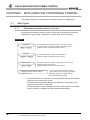
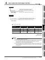
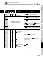
3.3
SPECIFICATIONS AND FUNCTIONS
Specifications of I/O Signals with Programmable Controller CPU
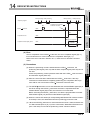
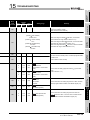
3.3.1
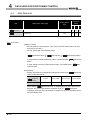
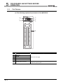
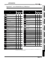
List of I/O signals with programmable controller CPU
The QD72P3C3 uses 32 input points and 32 output points for exchanging data with the
programmable controller CPU.
The I/O signals when the QD72PC3 is mounted in slot 0 of the main base unit are shown
below.
Device X refers to the signals input from the QD72P3C3 to the programmable controller
CPU, and device Y refers to the signals output from the programmable controller CPU to
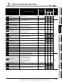
the QD72P3C3.
Signal direction: QD72P3C3
programmable
Signal direction: Programmable controller CPU
controller CPU
Device No.
3-4
Signal name
QD72P3C3
Device No.
Signal name
Programmable controller CPU READY
X0
Module READY signal
Y0
X1
X2
X3
X4
X5
X6
X7
X8
X9
XA
XB
XC
XD
XE
XF
X10
X11
X12
Axis 1/CH1 error occurrence signal
Axis 2/CH2 error occurrence signal
Axis 3/CH3 error occurrence signal
Axis 1/CH1 warning occurrence signal
Axis 2/CH2 warning occurrence signal
Axis 3/CH3 warning occurrence signal
Use prohibited
Axis 1 BUSY signal
Axis 2 BUSY signal
Axis 3 BUSY signal
Use prohibited
Axis 1 Axis 1 start complete signal
Axis 2 start complete signal
Axis 3 start complete signal
Use prohibited
Axis 1 positioning complete signal
Axis 2 positioning complete signal
Axis 3 positioning complete signal
Y1
Y2
Y3
Y4
Y5
Y6
Y7
Y8
Y9
YA
YB
YC
YD
YE
YF
Y10
Y11
Y12
signal
Axis 1/CH1 error reset signal
Axis 2/CH2 error reset signal
Axis 3/CH3 error reset signal
Axis 1 stop signal
Axis 2 stop signal
Axis 3 stop signal
Use prohibited
Axis 1 positioning start signal
Axis 2 positioning start signal
Axis 3 positioning start signal
Use prohibited
Axis 1 forward run JOG start signal
Axis 1 reverse run JOG start signal
Axis 2 forward run JOG start signal
Axis 2 reverse run JOG start signal
Axis 3 forward run JOG start signal
Axis 3 reverse run JOG start signal
Use prohibited
X13
X14
X15
X16
X17
X18
X19
X1A
X1B
X1C
X1D
X1E
X1F
Use prohibited
CH1 count value large
CH1 count value coincidence
CH1 count value small
Use prohibited
CH2 count value large
CH2 count value coincidence
CH2 count value small
Use prohibited
CH3 count value large
CH3 count value coincidence
CH3 count value small
Use prohibited
Y13
Y14
Y15
Y16
Y17
Y18
Y19
Y1A
Y1B
Y1C
Y1D
Y1E
Y1F
Use prohibited
CH1 coincidence signal reset command
CH2 coincidence signal reset command
CH3 coincidence signal reset command
Use prohibited
CH1 preset command
CH2 preset command
CH3 preset command
Use prohibited
CH1 count enable command
CH2 count enable command
CH3 count enable command
Use prohibited
3.3 Specifications of I/O Signals with Programmable Controller CPU
3.3.1 List of I/O signals with programmable controller CPU
SPECIFICATIONS AND FUNCTIONS
IMPORTANT
2
SYSTEM
CONFIGURATION
X07, X0B, X0F, X13, X17, X1B, X1F, Y07, Y0B, Y12, Y13, Y17, Y1B, Y1F are
used by the system, and cannot be used by the user.
If used, the operations of the QD72P3C3 are not ensured.
PRODUCT OUTLINE
1
SPECIFICATIONS
AND FUNCTIONS
3
DATA USED FOR
POSITIONING
CONTROL
4
PROCEDURES AND
SETTINGS BEFORE
OPERATION
5
UTILITY PACKAGE
(GX Configurator-PT)
6
SEQUENCE
PROGRAM USED
FOR POSITIONING
7
8
OPR CONTROL
3
3.3 Specifications of I/O Signals with Programmable Controller CPU
3.3.1 List of I/O signals with programmable controller CPU
3-5
3
SPECIFICATIONS AND FUNCTIONS
3.3.2
Details of input signal (QD72P3C3
CPU)
programmable controller
The following table shows the details of input signals.
Device
Signal name
No.
Description
(1) When the programmable controller CPU READY signal (Y0) is turned
from OFF to ON, the parameter setting range is checked. If no error is
found, this signal turns ON. (When the error occurrence signal (X1 to X3)
is ON, this signal does not turn ON even if the programmable controller
CPU READY signal (Y0) is turned from OFF to ON.)
OFF: Not prepared/
X0
Module READY signal
watch dog timer error
ON: Prepared
(2) When the programmable controller CPU READY signal (Y0) is turned
OFF, this signal turns OFF.
(3) When a watch dog timer error occurs, this signal turns OFF.
(4) This signal is used for an interlock of sequence programs.
Programmable controller
CPU READY signal (Y0)
ON
OFF
ON
Module READY signal (X0) OFF
(1) Module error occurrence status is displayed for each axis (each CH).
X1
Axis 1/CH1 Error
X2
Axis 2/CH2 occurrence
X3
Axis 3/CH3 signal
OFF: No error
ON: Error occurrence
(2) This signal turns OFF when the error reset signal (Y1 to Y3) is turned
ON.
(3) Error code can be checked by "
Axis/CH error code" for each axis
Md.5
(each CH).
(1) Module warning occurrence status is displayed for each axis (each CH).
X4
Axis 1/CH1 Warning
X5
Axis 2/CH2 occurrence ON: warning
X6
Axis 3/CH3 signal
OFF: No warning
occurrence
(2) This signal turns OFF when the axis/CH error reset signal (Y1 to Y3) is
turned ON.
(3) Warning code can be checked by "
Md.7
Axis/CH warning code" for each
axis (each CH).
X8
Axis 1
X9
Axis 2
XA
Axis 3
(1) This signal turns ON at the start of positioning control, OPR control or
BUSY
OFF: Not BUSY
signal*1
ON: BUSY
JOG operation. It turns OFF after positioning control stops (This signal
remains ON during positioning control).
(2) This signal turns OFF at error or stop.
(1) This signal turns ON when the positioning start signal (Y8 to YA) is turned
ON and the QD72P3C3 starts the positioning control process.
(The signal turns ON during OPR control. The signal does not turn ON
XC
Axis 1
Start
XD
Axis 2
complete
XE
Axis 3
signal
OFF: Start incomplete
ON: Start complete
during JOG operation.)
ON
Positioning start signal
(Y8 to YA)
Start complete signal
(XC to XE)
OFF
ON
OFF
(1) This signal turns ON for a time set in "
Md.7
Pr.6
Positioning complete signal
output time" after position control is completed for each axis.
X10
Axis 1
Positioning
X11
Axis 2
complete
X12
Axis 3
signal*2
OFF: Positioning
(The signal does not turn ON when "
incomplete
time" is 0.
ON: Positioning
complete
Md.7
Pr.6
Positioning complete signal output
(2) While this signal is ON, starting positioning control (including OPR
control) or JOG operation causes the signal to be OFF.
(3) This signal does not turn ON at the completion of JOG operation.
(4) This signal does not turn ON if the position control is stopped midway.
3-6
3.3 Specifications of I/O Signals with Programmable Controller CPU
3.3.2 Details of input signal (QD72P3C3 programmable controller CPU)
3
SPECIFICATIONS AND FUNCTIONS
Signal name
Description
OFF: Count value
X18
CH2
X1C
CH3
Coincidence detection
Count value point setting,
large
ON: Count value
(1) This signal turns ON when "
Md.3
Count value"
"
Cd.7
Coincidence
Coincidence detection
point setting
X15
CH1
X19
CH2
X1D
CH3
OFF: Count value not
Count value coincided,
coincidence ON: Count value
coincided
(1) This signal latches at ON when "
"
Cd.7
Md.3
Count value" =
Coincidence detection point setting".
(2) This signal turns OFF when the coincidence signal reset request is
turned ON.
OFF: Count value
CH2
X1E
CH3
small
ON: Count value
(1) This signal turns ON when "
Md.3
Count value"
"
Cd.7
Coincidence
detection point setting".
Coincidence detection
point setting
4
IMPORTANT
*1: The BUSY signal (X8 to XA) turns ON even when position control of
movement amount 0 is performed. However, since the ON time is short, the
ON status may not be detected in the sequence program.
*2: Position control completion of the QD72P3C3 refers to the point when the
pulse output from the QD72P3C3 is completed. Thus, even if the positioning
complete signal (X10 to X12) of the QD72P3C3 turns ON, the system may
continue operation.
5
6
UTILITY PACKAGE
(GX Configurator-PT)
X1A
Coincidence detection
Count value point setting,
7
SEQUENCE
PROGRAM USED
FOR POSITIONING
CH1
3
8
OPR CONTROL
X16
2
detection point setting".
SYSTEM
CONFIGURATION
CH1
SPECIFICATIONS
AND FUNCTIONS
X14
DATA USED FOR
POSITIONING
CONTROL
No.
PROCEDURES AND
SETTINGS BEFORE
OPERATION
Device
PRODUCT OUTLINE
1
3.3 Specifications of I/O Signals with Programmable Controller CPU
3.3.2 Details of input signal (QD72P3C3 programmable controller CPU)
3-7
3
SPECIFICATIONS AND FUNCTIONS
3.3.3
Details of output signals (programmable controller CPU
QD72P3C3)
The following table shows the details of output signals.
Device
No.
Signal name
Description
(1) This signal notifies the QD72P3C3 that the programmable controller CPU is
normal.
It is turned ON/OFF with the sequence program.
OFF:
Programmable
Y0
Programmable controller
CPU READY signal
controller CPU
READY OFF,
ON: Programmable
controller CPU
READY ON
This signal is turned ON during positioning control, OPR control and JOG
operation.
(2) When changing parameters or OPR data, turn OFF this signal.
(3) The QD72P3C3 processes the following when this signal is turned from OFF
to ON.
The parameter and OPR data setting range is checked.
The module READY signal (X0) turns ON.
(4) The QD72P3C3 processes the following when this signal is turned from ON
to OFF. In these cases, the OFF time should be set to 100ms or more.
The module READY signal (X0) turns OFF.
The operating axis stops.
(1) When the axis/CH error or the axis/CH warning occurs, turning ON this
Y1
Axis 1/CH1
Y2
Axis 2/CH2
Y3
Axis 3/CH3
OFF: Error reset not
Error reset
requested
signal
ON: Error reset
requested
signal clears the error, and "
Md.5
Axis/CH error code" and "
Md.7
Axis/CH
warning code" are cleared.
(2) By turning ON this signal during error occurrence, "
Md.4
Axis operation
status" changes from "Error" to "Standby".
(1) When this signal is turned ON, the OPR control, positioning control and JOG
Y4
Axis 1
Y5
Axis 2
Y6
Axis 3
OFF: Axis stop not
Axis stop
requested
signal
ON: Axis stop
requested
operation stop. In these cases, the ON time should be set to 4ms or more.
If ON time is less than 4ms, the OPR control, positioning control and JOG
operation may not stop.
(2) Turning ON this signal during operation decelerates the axis to a stop. At
this time, "
Md.4
Axis operation status" changes from "Deceleration (Axis
stop signal (Y4 to Y6) ON)" to "Stopped".
Y8
Axis 1
Y9
Axis 2
YA
Axis 3
OFF: Positioning
Positioning start not requested
start signal
ON: Positioning
start requested
(1) OPR control and positioning control are started.
(2) The positioning start becomes valid at the rising edge, and the operation is
started.
(3) When this signal is turned ON during BUSY, the "Start during operation"
warning (warning code: 10) occurs.
Axis 1
forward run
Axis 1
YC
reverse run
YD
Axis 2
YE
forward run
JOG start
YF
Axis 2
signal
Y10
reverse run
Y11
Axis 3
OFF: JOG not
started
ON: JOG started
(1) While this signal is ON, JOG operation is performed at the "
(2) When this signal is turned from ON to OFF, it decelerates to stop.
forward run
Axis 3
reverse run
3-8
JOG.1
speed".
3.3 Specifications of I/O Signals with Programmable Controller CPU
3.3.3 Details of output signals (programmable controller CPU QD72P3C3)
JOG
3
SPECIFICATIONS AND FUNCTIONS
Signal name
Description
OFF: Coincidence
Y14
CH1
Y15
CH2
Y16
CH3
Coincidenc signal reset not
e signal
commanded
reset
ON: Coincidence
command
signal reset
(1) This signal is turned ON when resetting the count value coincidence (X15,
X19, and X1D).
2
commanded
commanded
command
ON: Preset
Y1A
CH3
Y1C
CH1
Count
Y1D
CH2
enable
Y1E
CH3
command
(1) On the rising edge of this signal, "
"
Md.3
Cd.6
Preset value setting" is set to
Count value".
commanded
OFF: Count enable
not commanded
ON: Count enable
3
(1) By turning ON this signal, the counting operation is started.
SPECIFICATIONS
AND FUNCTIONS
commanded
DATA USED FOR
POSITIONING
CONTROL
4
5
PROCEDURES AND
SETTINGS BEFORE
OPERATION
CH2
6
UTILITY PACKAGE
(GX Configurator-PT)
Y19
OFF: Preset not
Preset
7
SEQUENCE
PROGRAM USED
FOR POSITIONING
CH1
8
OPR CONTROL
Y18
SYSTEM
CONFIGURATION
Device
No.
PRODUCT OUTLINE
1
3.3 Specifications of I/O Signals with Programmable Controller CPU
3.3.3 Details of output signals (programmable controller CPU QD72P3C3)
3-9
3
SPECIFICATIONS AND FUNCTIONS
3.4
List of Buffer Memory Addresses
The following is a list of buffer memory addresses.
In addition, for the details, such as a setting value, of each buffer memory, refer to
"Chapter 4 DATA USED FOR POSITIONING CONTROL".
Buffer memory
address for
Item
Pr.1
Setting value, setting range
Software stroke limit upper
limit value
Pr.2
Software stroke limit lower
limit value
1: Update
Pr.4
Speed limit value
1 to 100000 (pulse/s)
Pr.6
output time
1 to 100000 (pulse/s)
0 to 65535 (ms)
2/
3/
CH2
CH3
0
100
200
101
201
2
102
202
3
103
203
5
105
205
6
106
206
7
107
207
8
108
208
9
109
209
300
10
110
210
2
11
111
211
0
13
113
213
-1073741824
0: No update
1/
CH1
1
-1073741824 to 1073741823 (pulse)
speed control
Positioning complete signal
Axis Axis Axis
1073741823
Current feed value during
Bias speed at start
setting
value
-1073741824 to 1073741823 (pulse)
Pr.3
Pr.5
Factory default
0
8000
1
Reference
0: 1ms
Pr.7
Deviation counter clear
1: 2ms
signal output time
2: 10ms
3: 20ms
0: Values not changed simultaneously
Current feed value, count
Pr.9
value simultaneous change
function selection
1: Count value changed together at current value
change
2: Current feed value changed together at preset
Section
3: Values changed both at current value change
4.2
and at preset
0: OPR method 1) Near-point dog method
Pr.10
OPR method
Pr.11
OPR direction
Pr.12
OP address
Pr.13
1: OPR method 2) Stopper 3
0: Forward direction
1: Reverse direction
-1073741824 to 1073741823 (pulse)
OPR speed
1 to 100000 (pulse/s)
Pr.14
Creep speed
1 to 100000 (pulse/s)
Pr.15
ACC/DEC time at OPR
1 to 5000 (ms)
Ring counter upper limit
Pr.16
value
Positioning range upper
Pr.17
Pr.18
Pr.19
limit value
0 to 1073741823
0 to 1073741823 (pulse)
Coincidence detection
0: Coincidence detection not request
setting
1: Coincidence detection requested
Count value selection at
0: OP address not set to count value
OPR
1: OP address set to count value
3 - 10
0
20
120
220
0
21
121
221
22
122
222
23
123
223
24
124
224
25
125
225
26
126
226
0
1
1
27
127
227
28
128
228
30
130
230
31
131
231
32
132
232
33
133
233
0
34
134
234
0
35
135
235
1000
0
0
3.4 List of Buffer Memory Addresses
3.3.3 Details of output signals (programmable controller CPU QD72P3C3)
3
SPECIFICATIONS AND FUNCTIONS
address for
Cd.2
Cd.3
Cd.4
New speed value
ACC/DEC time at speed
change
Speed change request
1
1 to 5000 (ms)
1000
1 to 100000 (pulse/s)
0: Speed change not requested
1: Speed change requested
OPR request flag OFF
0: OPR request flag OFF complete
request
1: OPR request flag OFF requested
2/
3/
CH2
CH3
40
140
240
41
141
241
Section
42
142
242
150
250
51
151
251
1000
52
152
252
0
54
154
254
0
55
155
255
0
56
156
256
60
160
260
61
161
261
62
162
262
Section
63
163
263
4.6
70
170
270
71
171
271
72
172
272
73
173
273
74
174
274
75
175
275
3
0: Positioning control
Cd.5
Start method
9000: Machine OPR control
9001: Fast OPR control
Preset value setting
Coincidence detection point
Cd.7
Md.1
Md.2
setting
-1073741824 to 1073741823
-1073741824 to 1073741823
Current feed value
-
Current speed
-
0
0
0
0
Md.3
Count value
-
0
Md.4
Axis operation status
-
0
76
176
276
Md.5
Axis/CH error code
-
0
77
177
277
Md.7
Axis/CH warning code
-
0
78
178
278
Md.7
Status
-
0002H
79
179
279
Md.8
External I/O signal
-
0000H
80
180
280
0
90
190
290
0
91
191
291
Da.1
Operation pattern
0: Positioning start (independent)
5000 : Positioning start (continuous)
5
6
0: No control method
1: 1-axis linear control (ABS)
Control method
2: 1-axis linear control (INC)
3: Speed control (forward run)
Section
4: Speed control (reverse run)
4.4
5: Current value change
Da.4
ACC/DEC time
Command speed
Positioning address/
Da.5
movement amount
1 to 5000 (ms)
1 to 100000 (pulse/s)
-1073741824 to 1073741823 (pulse)
1000
1
0
92
192
292
94
194
294
95
195
295
96
196
296
97
197
297
8
OPR CONTROL
Da.3
7
SEQUENCE
PROGRAM USED
FOR POSITIONING
Da.2
4
PROCEDURES AND
SETTINGS BEFORE
OPERATION
Cd.6
2
4.3
50
1
1 to 5000 (ms)
1/
CH1
Reference
SYSTEM
CONFIGURATION
Cd.1
JOG ACC/DEC time
1 to 100000 (pulse/s)
Axis Axis Axis
SPECIFICATIONS
AND FUNCTIONS
JOG.2
JOG speed
setting
value
DATA USED FOR
POSITIONING
CONTROL
JOG.1
Setting value, setting range
UTILITY PACKAGE
(GX Configurator-PT)
Item
Factory default
PRODUCT OUTLINE
1
Buffer memory
3.4 List of Buffer Memory Addresses
3.3.3 Details of output signals (programmable controller CPU QD72P3C3)
3 - 11
3
3.5
SPECIFICATIONS AND FUNCTIONS
Specifications of I/O Interfaces with External Device
3.5.1
Electrical specifications of I/O signals
(1) Input specifications
(a) Input specifications of external input device for positioning
Rated input
Signal name
voltage/
current
5VDC/18mA
Operating
ON voltage/
OFF voltage/
Input
Response
voltage range
current
current
resistance
time
Approx.
0.1ms or
4.5 to 5.5VDC
2.7VDC or more/ 1.0VDC or less/
5.5mA or more
0.5mA or less
390
less
•The minimum pulse width is as follows.
Zero signal (PG0)
ON
3 s or less
3 s or less
0.1ms or more
OFF
Near-point dog signal
(DOG)
Upper limit signal (FLS)
24VDC/5mA
19.2 to
17.5VDC or more/
26.4VDC
3.0mA or more
Lower limit signal (RLS)
3 - 12
3.5 Specifications of I/O Interfaces with External Device
3.5.1 Electrical specifications of I/O signals
7.0VDC or
less/0.9mA or
less
Approx.
6.8k
1ms or less
3
SPECIFICATIONS AND FUNCTIONS
Signal name
5VDC
24VDC
Rated input
Operating
voltage/
voltage
current
range
5VDC/18mA
Input
Response
current
resistance
time
5.5mA or more
21.6 to 26.4V
6mA
OFF voltage/
current
2.7VDC or more/
4.5 to 5.5V
24VDC/2 to
ON voltage/
1.0VDC or
Approx.
less/0.5mA or
390
less
21.6VDC or more/
5VDC or less/
2mA or more
0.1mA or less
1 s or less
Approx.
3900
1 s or less
+390
•Input pulse can be selected from 1 multiple of 2 phases, 2 multiples of 2 phases, 4 multiples
2
SYSTEM
CONFIGURATION
(b) Input specifications for the counter function
PRODUCT OUTLINE
1
3
of 2 phases, and CW/CCW.
CW/CCW
1 multiples of
2 phases
2 multiples of
2 phases
4 multiples of
2 phases
A
A
B
B
A
A
B
B
A
A
B
B
A
A
B
B
4
5
(CH A_5V/CH A_24V)
•The minimum count pulse width is as follows.
Phase B pulse input
10 s
6
UTILITY PACKAGE
(GX Configurator-PT)
(CH B_5V/CH B_24V)
5 s5 s
Duty ratio 50%
(Minimum phase difference for 2-phase input: 2.5 s)
•The rise/fall time is as follows.
7
t
Both 1 and 2-phase input
t = 1.25
or less
100kPPS
t = 2.5
or less
100kPPS
t = 25
t
t = 500
or less
SEQUENCE
PROGRAM USED
FOR POSITIONING
Rise/fall time
100k
10kPPS
-
8
•Input pulse can be selected from 1 multiple of 2 phases, 2 multiples of 2 phases, 4 multiples
of 2 phases, and CW/CCW.
Set it in pulse input mode of "Intelligent function module switch setting" (refer to Section 5.6).
3.5 Specifications of I/O Interfaces with External Device
3.5.1 Electrical specifications of I/O signals
3 - 13
OPR CONTROL
Phase A pulse input
For subtraction count
DATA USED FOR
POSITIONING
CONTROL
For addition count
mode
PROCEDURES AND
SETTINGS BEFORE
OPERATION
Pulse input
SPECIFICATIONS
AND FUNCTIONS
Set it in pulse input mode of "Intelligent function module switch setting" (refer to Section 5.6).
3
SPECIFICATIONS AND FUNCTIONS
(2) Output specifications
(a) Input specifications of external input device for positioning
Signal name
Rated load
voltage
Operating
Max. load
load voltage
current/inrush
range
current
50mA/point /
4.75 to
5 to 24VDC
30VDC
200mA 10ms or
Max. voltage
Leakage
drop at ON
5VDC (TYP)
current
Response time
at OFF
0.1mA
-
or less
less
•Set pulse output mode and pulse output logic selection with "Intelligent function module switch
setting" (refer to Section 5.6).
•The following table shows the relationship of "Pulse output mode" and "Pulse output logic
selection" with pulse output.
Pulse
Pulse output F (PUSE F)
output
(CW/PULSE)
mode
Pulse output R (PUSE R)
(CCW/SIGN)
Pulse output logic selection
Positive logic
Negative logic
Forward run
Reverse run
Forward run
Reverse run
CW/CCW
PULSE/
SIGN
High
Low
Low
High
The rise/fall time and duty ratio are as the table on the next page.*
ON
OFF
tr
Deviation counter clear
(CLEAR)
3 - 14
5 to 24VDC
tf
4.75 to
30VDC
0.1A/point
0.4A, 10ms or
less
3.5 Specifications of I/O Interfaces with External Device
3.5.1 Electrical specifications of I/O signals
2ms or less
1VDC (TYP)
0.1mA
2.5VDC (MAX)
or less
(resistance load),
pulse width is
from 1 to 20ms.
3
SPECIFICATIONS AND FUNCTIONS
*: Pulse rise/fall time (unit tr.tf: s Duty:%) ... Ambient air temperature is assumed to be ordinary temperature.
10
20
50
Load voltage (V)
Cable length (m)
Load
Pulse
current
speed
(mA)
(kpps)
2
5
10
20
50
100
10
100
10
100
10
100
10
100
10
2.341
2.849
1.101
1.114
0.511
0.522
0.268
0.262
0.098
0.097
0.156
0.169
0.176
0.174
0.188
0.187
0.218
0.218
0.344
0.347
44.76
49.1
49.7
49.6
51.4
50.15
52.37
50.24
53.34
50.34
tf
(Rise)
(Fall)
2.824
3.727
1.487
1.516
0.753
0.745
0.379
0.376
0.140
0.135
0.162
0.182
0.188
0.190
0.203
0.204
0.233
0.234
0.359
0.361
Duty
2
42.45
49.08
48.37
49.83
50.89
50.09
52.18
50.22
53.33
50.34
SYSTEM
CONFIGURATION
5
100
10
100
10
100
10
100
10
100
10
(Fall)
tr
4
4.75
1
tr
tf
(Rise)
(Fall)
0.510
0.492
0.207
0.201
0.097
0.098
0.039
0.038
0.015
0.014
0.107
0.107
0.117
0.113
0.129
0.128
0.160
0.159
0.255
0.254
2
Duty
50.87
50.08
51.8
50.19
52.29
50.23
52.75
50.28
53.41
50.34
3
SPECIFICATIONS
AND FUNCTIONS
2
(Rise)
Duty
tr
tf
(Rise)
(Fall)
0.712
0.680
0.289
0.288
0.138
0.131
0.055
0.054
0.016
0.016
0.113
0.112
0.120
0.119
0.131
0.130
0.159
0.158
0.258
0.259
Duty
50.38
50.04
51.74
50.18
52.28
50.23
52.80
50.28
53.47
50.36
DATA USED FOR
POSITIONING
CONTROL
(kpps)
tf
5
PROCEDURES AND
SETTINGS BEFORE
OPERATION
(mA)
tr
6
UTILITY PACKAGE
(GX Configurator-PT)
speed
2
7
SEQUENCE
PROGRAM USED
FOR POSITIONING
current
26.4
1
8
OPR CONTROL
Load voltage (V)
Cable length (m)
Load
Pulse
PRODUCT OUTLINE
1
3.5 Specifications of I/O Interfaces with External Device
3.5.1 Electrical specifications of I/O signals
3 - 15
3
SPECIFICATIONS AND FUNCTIONS
3.5.2
Signal layout for external device connector
The specifications of the connector section, which is the I/O interface for the QD72P3C3
and external device, are shown below.
CON2 (for axis 3)
Pin layout
Pin
Signal name
No.
B20
B19
B18
B17
B16
B15
B14
B13
B12
B11
B10
B9
B8
B7
B6
B5
B4
B3
B2
B1
A20
A19
A18
A17
A16
A15
A14
A13
A12
A11
A10
A9
A8
A7
A6
A5
A4
A3
A2
A1
Pin
Signal name
No.
No.
Signal name
B20 NC
A20
CH3A_24V
B20
CH2A_24V
B19 NC
A19
CH3A_5V
B19
CH2A_5V
*1
Pin
Signal name
No.
A20 CH1A_24V
A19 CH1A_5V
B18 NC
A18
CH3A COM
B18
CH2A COM
A18 CH1A COM*1
B17 NC
A17
CH3B_24V
B17
CH2B_24V
A17 CH1B_24V
B16 NC
A16
CH3B_5V
B16
CH2B_5V
B15 NC
A15
CH3B COM
B15
CH2B COM
A15 CH1B COM*2
B14 NC
A14
PG03
B14
PG02
A14 PG01
B13 NC
A13
PG03 COM
B13
PG02 COM
A13 PG01 COM*3
B12 NC
A12
CLEAR3
B12
CLEAR2
A12 CLEAR1
B11
NC
A11
CLEAR3 COM*4
B11
CLEAR2 COM*4
A11
B10 NC
A10
DOG3
B10
DOG2
A10 DOG1
B9
NC
A9
COM1-3
B9
COM1-3
A9
COM1-3
B8
NC
A8
FLS3
B8
FLS2
A8
FLS1
*2
*3
*5
*5
*1
A16 CH1B_5V
*2
*3
*5
*5
NC
A7
COM1-3
B7
COM1-3
A7
COM1-3*5
B6
NC
A6
RLS3
B6
RLS2
A6
RLS1
A5
COM1-3
A4
PULSE F1
*5
B5
NC
A5
COM1-3
B4
NC
A4
PULSE F3
*5
B5
COM1-3
B4
PULSE F2
NC
A3
PULSE COM1-3
B3
PULSE COM1-3
A3
PULSE COM1-3*6
B2
NC
A2
PULSE R3
B2
PULSE R2
A2
PULSE R1
A1
PULSE COM1-3
A1
*6
B1
PULSE COM1-3
*6
*5
B3
NC
*6
*5
CLEAR1 COM*4
B7
B1
*6
PULSE COM1-3
* 1 Common for CH
A_5V, CH
A_24V (
indicates any of channel numbers 1 to 3.)
* 2 Common for CH
B_5V, CH
B_24V (
indicates any of channel numbers 1 to 3.)
* 3 Common for PG0
(
* 4 Common for CLEAR
* 5 Common for DOG
indicates any of axis numbers 1 to 3.)
(
indicates any of axis numbers 1 to 3.)
, FLS
* 6 Common for PULSE F
3 - 16
CON1 (for axes 1 and 2)
Pin
, RLS
, PULSE R
(
indicates any of axis numbers 1 to 3.)
(
3.5 Specifications of I/O Interfaces with External Device
3.5.2 Signal layout for external device connector
indicates any of axis numbers 1 to 3.)
*6
3
SPECIFICATIONS AND FUNCTIONS
Pin No.
Symbol
Signal details
(Negative logic is selected by external I/O signal logic selection)
•Input the zero signal for machine OPR control.
Use the encoder's zero signal and so on.
Zero signal
A14
B14
PG0
•Use this signal when "
Pr.10
Pr.10
OPR method" is the stopper 3 and the
OPR complete is input from an external device.
•The zero signal is detected at turning from OFF to ON.
Zero signal common
A13
B13
PG0 COM •Common for zero signal
•This signal is used for detecting the near-point dog during machine OPR
Near-point dog signal
A10
B10
DOG
control.
•The near-point dog signal is detected at turning from OFF to ON.
•Input this signal from the limit switch, which is set to the stroke upper
Upper limit signal
A8
B8
FLS
limit position.
•Turning OFF this signal stops positioning.
•Input this signal from the limit switch, which is set to the stroke lower
Lower limit signal
A6
B6
A9
B9
A7
B7
A5
B5
RLS
limit position.
•Turning OFF this signal stops positioning.
Common
COM
•Common for near-point dog signal, upper limit signal, and lower limit
signal
Pr.7
Deviation
counter clear signal input time".
Deviation counter clear
A12
B12
CLEAR
•Use the drive unit that can reset the droop pulse amount in the internal
deviation counter when the QD72P3C3 turns this signal ON.
(Note) The deviation counter clear is a signal output by the QD72P3C3
during machine OPR control. It cannot output randomly.
common
A11
B11
A4
B4
CLEAR
COM
6
•Common for deviation counter clear
•This signal is used to output command pulses to the open collector
Pulse output F
PULSE F
compatible unit.
CW/CCW mode: CW, PULSE/SIGN mode: PULSE
•This signal is used to output command pulses to the open collector
Pulse output R
A2
B2
PULSE R
7
compatible unit.
A3
B3
PULSE
A1
B1
COM
A20
B20
CHA_24V •Phase A pulse input for 24V
Phase A pulse input 5V A19
Phase A common
A18
Phase B pulse input
A17
24V
B19
B18
CHA_5V •Phase A pulse input for 5V
CHA COM •Common for phase A pulse
B17
CHB_24V •Phase B pulse input for 24V
Phase B pulse input 5V A16
Phase B common
A15
B16
B15
CHB_5V •Phase B pulse input for 5V
CHB COM •Common for phase B pulse
24V
•Common for pulse output F and pulse output R
3.5 Specifications of I/O Interfaces with External Device
3.5.3 List of I/O signal details
8
OPR CONTROL
Phase A pulse input
SEQUENCE
PROGRAM USED
FOR POSITIONING
CW/CCW mode: CCW, PULSE/SIGN mode: SIGN
Pulse output common
4
UTILITY PACKAGE
(GX Configurator-PT)
Deviation counter clear
3
5
•This signal is output during machine OPR control.
•The output time of the deviation counter clear is set in "
2
SYSTEM
CONFIGURATION
Signal name
SPECIFICATIONS
AND FUNCTIONS
The details of each signal for the QD72P3C3 external device connector are shown below.
DATA USED FOR
POSITIONING
CONTROL
List of I/O signal details
PROCEDURES AND
SETTINGS BEFORE
OPERATION
3.5.3
PRODUCT OUTLINE
1
3 - 17
3
SPECIFICATIONS AND FUNCTIONS
3.5.4
Internal circuit of I/O interface
The following shows the schematic diagram of the internal circuit of the interface for
external device connection of the QD72P3C3.
(for axis 1)
I/O
classification
External wiring
Pin
Internal circuit
No.
A14
390
1/3W
Signal name
Zero signal
PG0 1
2.2k
1/10W
A13
Input
A10
(for
6.8k
1/3W
680k
1/10W
6.8k
1/3W
680k
1/10W
6.8k
1/3W
680k
1/10W
A8
positioning)
A6
24VDC*
+
-
-
+
A9
A12
A11
Output
(for
Zero signal common
PG0 COM 1
Near-point dog signal
DOG 1
Upper limit signal
FLS 1
Lower limit signal
RLS 1
Common
COM 1-3
Deviation counter clear
CLEAR 1
Deviation counter clear
CLEAR
common
COM 1
A4
Pulse output F
PULSE F 1
A2
Pulse output R
PULSE R 1
A3
Pulse output common
positioning)
3.9k
1/3W
390
1/3W
A20
2.2k
1/10W
A19
Input
A18
(for counter
A17
function)
A16
3.9k
1/3W
390
1/3W
2.2k
1/10W
A15
*
3 - 18
PULSE
COM 1-3
Phase A pulse input 24V
CH1A_24V
Phase A pulse input 5V
CH1A_5V
Phase A common
CH1A COM
Phase B pulse input 24V
CH1B_24V
Phase B pulse input 5V
CH1B_5V
Phase B common
CH1B COM
Common terminal is available to both positive common and negative common (COM).
3.5 Specifications of I/O Interfaces with External Device
3.5.4 Internal circuit of I/O interface
SPECIFICATIONS AND FUNCTIONS
(a) Input signal ON/OFF status
The input signal ON/OFF status is defined by the external wiring and logic setting.
The following shows an example of the near-point dog signal (DOG).
(The other input signals also perform the same operations as the near-point dog
signal (DOG).)
Logic
setting*1
ON/OFF status of the near-point
External wiring*1,*2
dog signal (DOG) as seen from
the QD72P3C3
3
(Voltage not applied)
SPECIFICATIONS
AND FUNCTIONS
DOG
OFF
24VDC
COM
Negative logic
(Default value)
2
SYSTEM
CONFIGURATION
(1) Input signal ON/OFF status
PRODUCT OUTLINE
1
4
(Voltage applied)
DOG
DATA USED FOR
POSITIONING
CONTROL
ON
COM
(Voltage not applied)
5
DOG
COM
Positive logic
(Voltage not applied)
DOG
6
OFF
24VDC
COM
* 1 Set the logic setting using "Intelligent function module switch setting". For details of the setting
contents, refer to Section 5.6.
* 2 When using the upper limit signal (FLS) and/or the lower limit signal (RLS), always wire them/it as
the normally closed contact in the negative logic setting.
Turning OFF this signal stops positioning.
(b) Logic setting and internal circuit
In the QD72P3C3, the case where the internal circuit (photocoupler) is OFF in the
negative logic setting is defined as "input signal OFF".
Reversely, the case where the internal circuit (photocoupler) is OFF in the positive
logic setting is defined as "input signal ON".
(Photocoupler ON/OFF status)
• When voltage is not applied: Photocoupler OFF
• When voltage is applied: Photocoupler ON
3.5 Specifications of I/O Interfaces with External Device
3.5.4 Internal circuit of I/O interface
UTILITY PACKAGE
(GX Configurator-PT)
24VDC
PROCEDURES AND
SETTINGS BEFORE
OPERATION
ON
7
SEQUENCE
PROGRAM USED
FOR POSITIONING
24VDC
8
OPR CONTROL
3
3 - 19
4
DATA USED FOR POSITIONING CONTROL
CHAPTER4
DATA USED FOR POSITIONING CONTROL
This chapter describes the specifications of the data to be set to the QD72P3C3.
4.1
Data Types
4.1.1
Parameters and data required for control
The parameters and data required to perform control with the QD72P3C3 include the
following three types of data: "setting data", "monitor data", and "control data".
Setting data
Parameter
( Pr.1 to Pr. 19 )
JOG data
( JOG.1 and JOG..2 )
Positioning data
( Da.1 to Da..5 )
Set parameters for positioning, OPR, and counter function
according to the mechanical appliances and applications.
(Storage location: QD72P3C3 buffer memory)
Set values required to perform "JOG operation."
(Storage location: QD72P3C3 buffer memory)
Set values required to perform "positioning control" such as
speed and movement amount.
(Storage location: QD72P3C3 buffer memory)
Intelligent function module switches
(Switches 1 to 5)
Set the logics of the external I/O signal,
pulse output mode, and pulse input mode.
(Storage location: [I/O assignment] in
[PLC parameter] for QCPU)
• The parameters become valid when the programmable controller CPU READY
signal (Y0) is turned from OFF to ON.
• The JOG data and positioning data become valid when JOG operation and
positioning control starts, respectively.
• Use GX Developer to set the intelligent function module switches. (For details,
refer to "Section 5.6 Intelligent Function Module Switch Setting".)
4-1
4.1 Data Types
4.1.1 Parameters and data required for control
DATA USED FOR POSITIONING CONTROL
PRODUCT OUTLINE
1
Monitor data
Data related to the operations of the running
axes (e.g. the current positions, speeds,
error status, and warning status) are monitored
for each axis.
(Storage location: QD72P3C3 buffer memory)
Monitor data
2
SYSTEM
CONFIGURATION
( Md.1 to Md.8 )
Control data
3
SPECIFICATIONS
AND FUNCTIONS
Operation-related settings are made and control
such as speed change during operation is performed.
(Storage location: QD72P3C3 buffer memory)
( Cd.1 to Cd. 7 )
How to set "setting data"
GX Developer
(Initial setting*)
Parameter
JOG data
Positioning data
(Initial setting*)
5
Intelligent function module
switch
*
DATA USED FOR
POSITIONING
CONTROL
GX Configurator-PT
Initial setting is made to the intelligent function module parameters of the QCPU.
: Can be set.
: Cannot be set.
PROCEDURES AND
SETTINGS BEFORE
OPERATION
Sequence program
6
POINT
(1) Create "setting data" for each axis.
(2) The "setting data" parameters have determined default values, and have been
set to the default values before shipment from the factory. (Leave the
parameters for unused axes at the default values.)
(3) The "setting data" set in the QD72P3C3 buffer memory are not backed up. All
data are initialized at power-ON of the system or reset of the programmable
controller CPU.
UTILITY PACKAGE
(GX Configurator-PT)
Means
Setting item
4
7
SEQUENCE
PROGRAM USED
FOR POSITIONING
Axis control data
8
OPR CONTROL
4
4.1 Data Types
4.1.1 Parameters and data required for control
4-2
4
DATA USED FOR POSITIONING CONTROL
4.1.2
Parameter setting items
The following table shows the "parameter" setting items. Set "parameters" to each axis for
all controls using the QD72P3C3.
For details of each control, refer to "Chapter 8" to "Chapter 10".
For details of each setting item, refer to "Section 4.2 Parameter List".
Control
OPR control
Near-
Parameter
Software stroke limit
Pr.1
upper limit value
Pr.2
Software stroke limit lower
limit value
Current feed value during
Pr.3
speed control
Pr.4
Speed limit value
Pr.5
Bias speed at start
Pr.6
Positioning complete
point
Stopper
dog
3
method
Positioning control
Fast
OPR
control
-
-
-
-
-
-
-
-
-
-
-
Position Speed
control
control
Current
JOG
value
operation
change
signal output time
-
-
-
-
-
-
-
-
-
value simultaneous
-
-
-
-
-
-
-
-
-
-
-
-
-
change function selection
Pr.10
OPR method
-
Pr.11
OPR direction
-
-
-
-
OP address
-
-
-
-
Pr.13
OPR speed
-
-
-
-
Pr.14
Creep speed
-
-
-
-
Pr.15
ACC/DEC time at OPR
-
-
-
-
Ring counter upper limit
value
Positioning range upper
Pr.17
Pr.18
Pr.19
limit value
Coincidence detection
setting
-
-
-
-
-
-
-
-
-
-
-
-
-
-
-
Count value selection at
OPR
-
-
12.7
-
Section
12.3
Section
-
Section
-
Pr.12
Pr.16
-
-
Current feed value, count
Pr.9
function
11.4
-
Deviation counter clear
sub-
Section
signal output time
Pr.7
Related
12.5
-
Section
8.4
: Setting is required.
: Make setting as necessary. (If unnecessary, the field is represented with "-".)
- : Setting not required. (This is an irrelevant item, so the set value will be ignored. If the value is
the default value or within the setting range, there is no problem.)
: Setting items of machine OPR control (near-point dog method or count 3) are used for those of
fast OPR control.
4-3
4.1 Data Types
4.1.2 Parameter setting items
DATA USED FOR POSITIONING CONTROL
Setting ranges of Pr.1 to Pr.19 are checked when the "programmable controller CPU
READY signal (Y0)" output from the programmable controller CPU to the QD72P3C3 is
changed from OFF to ON. At this time, an error occurs in the parameter whose setting
value is outside the range. (For details, refer to "CHAPTER 15 TROUBLESHOOTING".)
PRODUCT OUTLINE
1
Checking the parameters
SYSTEM
CONFIGURATION
2
SPECIFICATIONS
AND FUNCTIONS
3
DATA USED FOR
POSITIONING
CONTROL
4
PROCEDURES AND
SETTINGS BEFORE
OPERATION
5
UTILITY PACKAGE
(GX Configurator-PT)
6
SEQUENCE
PROGRAM USED
FOR POSITIONING
7
8
OPR CONTROL
4
4.1 Data Types
4.1.2 Parameter setting items
4-4
4
DATA USED FOR POSITIONING CONTROL
4.1.3
JOG data setting items
The "JOG data" has to be set to perform "JOG operation". The following table shows the
"JOG data" setting items.
Set "JOG data" to each axis.
For details of "JOG operation" and details of each setting item, refer to "CHAPTER 10
JOG OPERATION" and "Section 4.3 JOG Data List", respectively.
JOG data
JOG.1
JOG speed
JOG.2
JOG ACC/DEC time
JOG operation
: Setting is required.
Checking the JOG data
Setting ranges of JOG.1 to JOG.2 are checked when the JOG operation starts. At this
time, an error occurs in the JOG data whose setting value is outside the range. (For
details, refer to "CHAPTER 15 TROUBLESHOOTING".)
4.1.4
Positioning data setting items
The "positioning data" has to be set to perform "positioning control". The following table
shows the "positioning data" setting items.
One "positioning data" can be set to per axis.
For details of "positioning control" and details of each setting item, refer to "CHAPTER 9
POSITIONING CONTROL" and "Section 4.4 Positioning Data List", respectively.
Positioning control
Positioning data
Position
control
Speed control
Current value
change
Da.1
Operation pattern
Da.2
Control method
Da.3
ACC/DEC time
-
Da.4
Command speed
-
Da.5
Positioning address/movement amount
-
: Setting is required.
- : Setting not required. (This is an irrelevant item, so the set value will be ignored. If the value is
the default value or within the setting range, there is no problem.)
Checking the positioning data
Setting ranges of Da.1 to Da.5 are checked when the positioning control starts. At this
time, an error occurs in the positioning data whose setting value is outside the range. (For
details, refer to "CHAPTER 15 TROUBLESHOOTING".)
4-5
4.1 Data Types
4.1.3 JOG data setting items
DATA USED FOR POSITIONING CONTROL
The monitor data area in the buffer memory stores the data showing the status of the
positioning control system. To operate the positioning control system, monitor these data
as necessary.
The following data are available for monitoring.
For details of monitor data, refer to "Section 4.5 Monitor Data List".
Monitor details
The current feed value is monitored.
Md.2
Current speed
The current speed is monitored.
Md.3
Count value
The count value of input pulse is stored.
Md.4
Axis operation status
The axis operation status is monitored.
Md.5
Axis/CH error code
Md.6
Axis/CH warning code
Md.8
Status
The flag is monitored.
Md.8
External I/O signal
The external I/O signal is monitored.
The latest code of the error which occurred in the axis is
monitored.
The latest code of the warning which occurred in the axis is
monitored.
Types and functions of control data
To operate the positioning control system, perform controls as necessary. (Defalut value is
stored to data to be used for controls at power-ON. However, the value can be set with the
sequence program as necessary.)
The following items can be controlled.
For details of control data, refer to "Section 4.6 Control Data List".
Control data
Description
New speed value
Cd.2
ACC/DEC time at speed change
Cd.3
Speed change request
Issues a command to change speed in operation to
Cd.4
OPR request flag OFF request
Switches the OPR request flag from "ON to OFF".
Cd.5
Start method
Set a control to be performed (start method).
Cd.6
Preset value setting
Cd.7
Coincidence detection point setting
Set the time until the speed reaches to the one after change from
the speed before change.
Set a value to be stored in "
Md.3
Cd.1
value.
7
Count value" by turning ON
the preset command.
Enter a value to be compared with "
Md.3
5
6
Set speed to be changed during operation.
Cd.1
DATA USED FOR
POSITIONING
CONTROL
4
PROCEDURES AND
SETTINGS BEFORE
OPERATION
4.1.6
3
SPECIFICATIONS
AND FUNCTIONS
Current feed value
UTILITY PACKAGE
(GX Configurator-PT)
Monitor data
Md.1
2
SYSTEM
CONFIGURATION
Types and functions of monitor data
Count value".
SEQUENCE
PROGRAM USED
FOR POSITIONING
4.1.5
PRODUCT OUTLINE
1
8
OPR CONTROL
4
4.1 Data Types
4.1.5 Types and functions of monitor data
4-6
4
DATA USED FOR POSITIONING CONTROL
4.2
Parameter List
Buffer memory
Parameter
Setting value, setting range
Factory
default value
address for setting
Axis
Axis
Axis
1/CH1 2/CH2 3/CH3
Pr.1
Software stroke limit upper
limit value
Pr.2
Software stroke limit lower
limit value
0
100
200
1
101
201
2
102
202
3
103
203
5
105
205
6
106
206
7
107
207
8
108
208
9
109
209
300
10
110
210
2
11
111
211
0
13
113
213
0
20
120
220
0
21
121
221
22
122
222
-1073741824 to 1073741823 (pulse)
1073741823
-1073741824 to 1073741823 (pulse)
-1073741824
Current feed value during
0: No update
speed control
1: Update
Pr.4
Speed limit value
1 to 100000 (pulse/s)*1
8000
Pr.5
Bias speed at start
1 to 100000 (pulse/s)*1
1
Pr.3
Positioning complete signal
Pr.6
output time
0 to 65535 (ms)
0
0: 1ms
Pr.7
Deviation counter clear
1: 2ms
signal output time
2: 10ms
3: 20ms
0: Values not changed simultaneously
Current feed value, count
Pr.9
value simultaneous change
function selection
1: Count value changed together at current value
change
2: Current feed value changed together at preset
3: Values changed both at current value change and
at preset
Pr.10
OPR method
Pr.11
OPR direction
Pr.12
OP address
Pr.13
OPR speed
Pr.14
Creep speed
Pr.15
ACC/DEC time at OPR
Ring counter upper limit
Pr.16
value
Positioning range upper limit
Pr.17
Pr.18
Pr.19
4-7
value
0: OPR method 1) Near-point dog method
1: OPR method 2) Stopper 3
0: Forward direction
1: Reverse direction
-1073741824 to 1073741823 (pulse)
1 to 100000 (pulse/s)*1
1 to 100000 (pulse/s)*1
1 to 5000
(ms)*2
0 to 1073741823 (pulse)
0 to 1073741823 (pulse)
Coincidence detection
0: Coincidence detection not request
setting
1: Coincidence detection requested
Count value selection at
0: OP address not set to count value
OPR
1: OP address set to count value
4.2 Parameter List
0
23
123
223
24
124
224
25
125
225
26
126
226
27
127
227
28
128
228
30
130
230
31
131
231
32
132
232
33
133
233
0
34
134
234
0
35
135
235
1
1
1000
0
0
DATA USED FOR POSITIONING CONTROL
1 to 8000
8001 to 32000
1-pulse unit
4-pulse unit
32001 to 64000 64001 to 100000
(pulse/s)
Pulse unit
8-pulse unit
25-pulse unit
When setting " Pr.4 Speed limit value" to 100000 (pulse/s) (when pulse unit is 25-pulse unit), set a
value which is "multiples of 25" to speed setting parameter and data.
If setting a value that does not satisfy the condition, the value is dropped so that it can be multiples of
25. Note if setting a value under 25, corresponding to pulse unit, an error occurs.
[Setting example of speed setting parameters and data when "
100000]
100000
Pr.4
Speed limit value
Pr.5
Bias speed at start
Pr.13
OPR speed
20000
Pr.14
Creep speed
1000
Da.4
Command speed
50000
Pr.4
Speed limit value" is set to
If Speed limit value is set to 100000
100
Set speed setting parameter and data so
that the values can be "multiples of 25".
Pr.15 Set ACC/DEC time at OPR within the range that the following formula is satisfied. If the
condition is not satisfied, "Out of ACC/DEC time setting valid range"warning (warning code: 26)
occurs, and control is performed in the time between the maximum value and the minimum value
calculated by the following formula. (Refer to "Example" below.)
Pr.13 OPR speed
1
Pr.1 4 Creep speed
5
8000
Pr.15 ACC/DEC time at OPR
Pulse unit(Refer to 1*)
0.125
[Example]
OPR speed: 8000,
Pr.14
Pr.15
Creep speed: 1, and
Pr.4
Speed limit value: 8000 (=1-
ACC/DEC time at OPR is from 8 to 5000 (ms).
6
UTILITY PACKAGE
(GX Configurator-PT)
Pr.13
pulse unit), the setting range of
7
SEQUENCE
PROGRAM USED
FOR POSITIONING
When
3
4
If 65090 is set to speed setting parameter or data, it is dropped to 65075, multiples of 25.
*2
2
SYSTEM
CONFIGURATION
Setting value
Pr.4
of "Speed limit value"
SPECIFICATIONS
AND FUNCTIONS
Speed
DATA USED FOR
POSITIONING
CONTROL
Pr.4
PROCEDURES AND
SETTINGS BEFORE
OPERATION
* 1 Setting unit (pulse unit) for speed setting data changes according to the value set to "
limit value" as the table below.
PRODUCT OUTLINE
1
8
OPR CONTROL
4
4.2 Parameter List
4-8
4
Pr.1
DATA USED FOR POSITIONING CONTROL
Software stroke limit upper limit value,
[Setting contents]
Pr.2
Software stroke limit lower limit value
Pr.1
: Set the upper limit for the machine movement range.
Pr.2
: Set the lower limit for the machine movement range.
Software stroke
limit Lower limit
(Machine movement range)
OP
Software stroke
limit upper limit
Emergency stop
limit switch
* 1 Generally, the OP is set at the lower limit or upper limit of the stroke limit.
* 2 By setting the upper limit value or lower limit value of the software stroke limit, overrun in the
software can be prevented. Also an emergency stop limit switch must be attached nearby the side
of outside the range.
Pr.3
Current feed value during speed control
[Setting contents]
Set whether to update " Md.1 Current feed value" at speed control.
0: No update
1: Update
Pr.4
The current feed value does not change. The current feed value at the start of
speed control is held.
The current feed value is updated. The current feed value at the start of speed
control is updated.
Speed limit value
[Setting contents]
Set the maximum speed for OPR control, positioning control and JOG operation.
The Speed limit value is determined by the following two conditions.
• The number of motor rotations
• Moving speed of workpiece
4-9
4.2 Parameter List
4
DATA USED FOR POSITIONING CONTROL
Bias speed at start
Setting value of
Pr.4
Speed limit
1 to 8000
8001 to 32000
32001 to 64000
64001 to 100000
1-pulse unit
4-pulse unit
8-pulse unit
25-pulse unit
value" (pulse/s)
Pulse unit
When setting " Pr.4 Speed limit value" to 100000 (pulse/s) (when pulse unit is
25-pulse unit), set a value which is "multiples of 25" to " Pr.5 Bias speed at
start".
If setting a value that does not satisfy the condition, the value is dropped so that it
can be multiples of 25. Note if setting a value under 25, corresponding to pulse
unit, "Out of bias speed at start setting range" error (error code: 906) occurs.
POINT
If the workpiece is dragged at start, the value set to Bias speed at start may be
small. In this case, set Bias speed at start using the following formula as a
reference.
Acceleration
125
Pulse unit
4
5
6
7
SEQUENCE
PROGRAM USED
FOR POSITIONING
Pr.5 Bias speed at start
SPECIFICATIONS
AND FUNCTIONS
• Setting unit (pulse unit) changes according to the value set to " Pr.4 Speed limit
value" as the table below.
3
DATA USED FOR
POSITIONING
CONTROL
If setting a value greater than " Pr.4 Speed limit value", "Out of bias speed at
start setting range" error (error code: 906) occurs.
PROCEDURES AND
SETTINGS BEFORE
OPERATION
• Set a value equal to or less than " Pr.4 Speed limit value".
UTILITY PACKAGE
(GX Configurator-PT)
[Precautions]
• The minimum starting speed during
"
2
SYSTEM
CONFIGURATION
[Setting contents]
• Set the minimum starting speed for positioning control and JOG operation.
• In case of using a motor such as a stepping motor, set this item to start the motor
smoothly. (A stepping motor does not start smoothly if the motor speed is low at
start.)
8
OPR CONTROL
Pr.5
PRODUCT OUTLINE
1
4.2 Parameter List
4 - 10
4
Pr.6
DATA USED FOR POSITIONING CONTROL
Positioning complete signal output time
[Setting contents]
• Set the output time of the positioning complete signal (X10 to X12) output from
the QD72P3C3.
• Positioning complete designates the status when the QD72P3C3 finishes
outputting pulses.
• If the setting value is 0 (ms) or the motor was stopped with the axis stop signal
(Y4 to Y6) during JOG operation or speed control, the positioning complete signal
(X10 to X12) are not output.
Programmable controller
CPU
module
Positioning
start signal
(Y8toYA)
QD72
P3C3
M
Positioning
complete signal
( X10 to X12)
Positioning control
Positioning start
signal (Y8 to YA)
Start complete signal
(XC to XE)
BUSY signal (X8 to XA)
Positioning
complete signal
Positioning complete
signal (X10 to X12)
Output time
Pr.7
Deviation counter clear signal output time
[Setting contents]
Set the duration for outputting the deviation counter clear signal during machine OPR
control. (For details, refer to the manual for the drive unit.)
4 - 11
4.2 Parameter List
4
DATA USED FOR POSITIONING CONTROL
Current feed value, count value simultaneous change function selection
[Setting contents]
Make setting to change " Md.1 Current feed value" and " Md.3 Count value" to the
same value at current value change or presetting.
0: Values not
changed
The current feed value, count value simultaneous change function is not used.
2
changed together at
Stores the value set to "
current value change value change execution to "
2: Current feed value
changed together at
preset
3: Values changed
both at current value
Stores the value set to "
feed value" and "
Md.3
Positioning address/movement amount"at current
Da.5
Md.1
Current feed value" and "
Md.3
Preset value setting" at preset to "
Cd.5
Count value".
Md.1
Current
Count value".
Stores the values set to "
Da.5
value change execution to "
Positioning address/movement amount" at current
Md.1
Current feed value" and "Md.3 Count value".
Cd.6 Preset value setting" at preset to "
change and at preset Stores the value set to "
feed value" and " Md.3 Count value".
Md.1
Current
3
SPECIFICATIONS
AND FUNCTIONS
1: Count value
SYSTEM
CONFIGURATION
simultaneously
DATA USED FOR
POSITIONING
CONTROL
4
PROCEDURES AND
SETTINGS BEFORE
OPERATION
5
UTILITY PACKAGE
(GX Configurator-PT)
6
SEQUENCE
PROGRAM USED
FOR POSITIONING
7
8
OPR CONTROL
Pr.9
PRODUCT OUTLINE
1
4.2 Parameter List
4 - 12
4
Pr.10
DATA USED FOR POSITIONING CONTROL
OPR method
[Setting contents]
Set "OPR method" for performing machine OPR control.
0: Near-point dog
After the axis decelerates at the near-point dog ON, it stops at the zero signal and
method
then the machine OPR control is completed.
After the axis starts rotating at creep speed, it stops at the stopper and then the
1: Stopper 3
machine OPR control is completed at zero signal.
For details of each OPR method, refer to "Section 8.2.2 OPR method for machine
OPR control".
[Machine OPR control operation]
0: Near-point dog method
(1) The machine OPR control is started.
(The axis starts movement in "
Pr.11
OPR direction"at "
OPR
Pr.13
V
Pr.13 OPR speed
(2)
speed".)
(2) The near-point dog ON is detected and deceleration starts.
(3) The axis decelerates until it reaches to "
Pr.14
Pr. 14 Creep speed
Creep speed", and
then starts moving at the Creep speed. (At this time, the near-point
(4)
(3)
(1)
t
ON
dog must be ON.)
Near-point dog OFF
(4) When the first zero signal (signal output for one pulse per one
First zero after
near-point dog OFF
rotation) after near-point dog OFF is detected, pulse output from the
Zero singal
QD72P3C3 stops, and the machine OPR control is completed.
1: Stopper 3
(1)
(The axis starts movement in "
Pr.11
OPR direction"at "
Pr.14
Creep
V
Pr.14 Creep speed
speed".) At this time, a torque limit to the motor is required. If torque
Stopped by stopper.
limit is not set, the motor may be a failure at (2).)
(2) The axis contacts against the stopper at "
Pr.14
t
(1)
Zero signal
then stops.
(3) When the zero signal (signal which detects a contact against a
stopper, and then is output) is detected, pulse output from the
QD72P3C3 stops, and the machine OPR control is completed.
4 - 13
(2)
Creep speed", and
4.2 Parameter List
(3)
4
DATA USED FOR POSITIONING CONTROL
Pr.11
OPR direction
[Setting contents]
Set the direction to start movement when starting machine OPR control.
0: Forward direction......Moves in the direction that the address increases. (Arrow 2))
1: Reverse direction......Moves in the direction that the address decreases. (Arrow 1))
" Pr.11 OPR direction" as shown below.
When the OP is set at the lower
limit side, the OPR direction is
in the direction of arrow 1).
Set "1" for Pr.11 .
1)
OP
SPECIFICATIONS
AND FUNCTIONS
Address increase
direction
Upper limit
Lower limit
Address decrease
direction
4
Address increase
direction
2)
OP
DATA USED FOR
POSITIONING
CONTROL
Address decrease
direction
3
Upper limit
Lower limit
2
SYSTEM
CONFIGURATION
Normally, OP is set near the lower limit switch or the upper limit switch. Therefore, set
PRODUCT OUTLINE
1
When the OP is set at the upper
limit side, the OPR direction is
in the direction of arrow 2).
Set "0" for Pr.11 .
OP address
[Setting contents]
Set an address used as the reference point for position control (ABS system).
When machine OPR control is completed, the value of " Md.1 Current feed value" is
6
UTILITY PACKAGE
(GX Configurator-PT)
changed to that of " Pr.12 OP address".
SEQUENCE
PROGRAM USED
FOR POSITIONING
7
8
OPR CONTROL
Pr.12
PROCEDURES AND
SETTINGS BEFORE
OPERATION
5
4.2 Parameter List
4 - 14
4
Pr.13
DATA USED FOR POSITIONING CONTROL
OPR speed
[Setting contents]
Set the speed for OPR control.
[Precautions]
• Set "OPR speed" to equal to or less than " Pr.4 Speed limit value". If the "Speed
limit value" is exceeded, "Out of OPR speed setting range" error (error code: 913)
occurs.
• Setting unit (pulse unit) for speed setting data changes according to the value set
to " Pr.4 Speed limit value" as the table below.
Setting value of
"
Pr.4
Speed limit
1 to 8000
8001 to 32000
32001 to 64000
64001 to 100000
1-pulse unit
4-pulse unit
8-pulse unit
25-pulse unit
value" (pulse/s)
Pulse unit
When setting " Pr.4 Speed limit value" to 100000 (pulse/s) (when pulse unit is
25-pulse unit), set a value which is "multiples of 25" to " Pr.13 OPR speed".
If setting a value that does not satisfy the condition, the value is dropped so that it
can be multiples of 25.
4 - 15
4.2 Parameter List
4
DATA USED FOR POSITIONING CONTROL
[Setting contents]
• Set the creep speed (low speed immediately before stop after deceleration from
OPR speed).
• The creep speed has influence to detection tolerance in OPR method with nearpoint dog method, and has influence to the size of impact at collision in OPR
method with the stopper 3.
[Precautions]
V
Pr.13 OPR speed
Machine OPR control
start
3
SPECIFICATIONS
AND FUNCTIONS
• Set "Creep speed" to equal to or less than " Pr.13 OPR speed". If the "OPR
speed" is exceeded, "Out of creep speed setting range" error (error code: 914)
occurs.
2
SYSTEM
CONFIGURATION
Creep speed
Pr.14 Creep speed
4
DATA USED FOR
POSITIONING
CONTROL
t
ON
Near-point dog signal OFF
Zero signal
to " Pr.4 Speed limit value" as the table below.
Setting value of
"
Pr.4
Speed limit
1 to 8000
8001 to 32000
32001 to 64000
64001 to 100000
1-pulse unit
4-pulse unit
8-pulse unit
25-pulse unit
value" (pulse/s)
Pulse unit
When setting " Pr.4 Speed limit value" to 100000 (pulse/s) (when pulse unit is
7
SEQUENCE
PROGRAM USED
FOR POSITIONING
25-pulse unit), set a value which is "multiples of 25" to " Pr.14 Creep speed".
If setting a value that does not satisfy the condition, the value is dropped so that it
can be multiples of 25. Note if setting a value under 25, corresponding to pulse
unit, "Out of creep speed setting range" error (error code: 914) occurs.
6
UTILITY PACKAGE
(GX Configurator-PT)
• Setting unit (pulse unit) for speed setting data changes according to the value set
PROCEDURES AND
SETTINGS BEFORE
OPERATION
5
8
OPR CONTROL
Pr.14
PRODUCT OUTLINE
1
4.2 Parameter List
4 - 16
4
Pr.15
DATA USED FOR POSITIONING CONTROL
ACC/DEC time at OPR
[Setting contents]
Set acceleration time from " Pr.14 Creep speed" to " Pr.13 OPR speed" and
deceleration time from " Pr.13 OPR speed" to " Pr.14 Creep speed" during machine
OPR control in near-point dog method.
V
Pr.13
Pr.14
t
Pr.15
Pr.15
[Precautions]
Set ACC/DEC time at OPR within the range that the following formula is satisfied. If
the condition is not satisfied, "Out of ACC/DEC time setting valid range" warning
(warning code: 26) occurs, and control is performed in the time between the maximum
value and the minimum value calculated by the following formula. (Refer to "Example"
below.)
Pr.13 OPR speed
1
Pr.1 4 Creep speed
8000
Pr.15 ACC/DEC time at OPR
Pulse unit
0.125
[Example]
When Pr.13 OPR speed: 8000, Pr.14 Creep speed: 1, and
Pr.4
Speed limit
value: 8000 (=1-pulse unit), the setting range of Pr.15 ACC/DEC time at OPR is
from 8 to 5000 (ms).
4 - 17
4.2 Parameter List
4
DATA USED FOR POSITIONING CONTROL
Ring counter upper limit value
[Setting contents]
• Set the upper limit value of count range when the ring counter is selected for the
counter format*.
• For details of ring counter, refer to "Section 12.3 Ring Counter Function".
2
: Select the counter format using the intelligent function module switch.
SYSTEM
CONFIGURATION
*
Md.3Count value
Pr.16 Ring counter upper limit value
3
SPECIFICATIONS
AND FUNCTIONS
Addition
0
DATA USED FOR
POSITIONING
CONTROL
4
PROCEDURES AND
SETTINGS BEFORE
OPERATION
5
UTILITY PACKAGE
(GX Configurator-PT)
6
7
SEQUENCE
PROGRAM USED
FOR POSITIONING
Subtraction
8
OPR CONTROL
Pr.16
PRODUCT OUTLINE
1
4.2 Parameter List
4 - 18
4
Pr.17
DATA USED FOR POSITIONING CONTROL
Positioning range upper limit value
[Setting contents]
• Set the upper limit value of positioning range when the ring counter is selected for
the counter format and positioning control is performed in absolute system.
When positioning control is performed at ring counter setting, the movable range
in absolute system is from 0 to " Pr.17 Positioning range upper limit value -1".
Md.1 Current feed value
Pr.17 Positioning range
upper limit valuea
Subtraction
Addition
0
• When Speed control or JOG operation is performed at ring counter setting,
" Md.1 Current feed value" is repeatedly updated between 0 and
" Pr.17 Positioning range upper limit value -1".
Md.1 Current feed value
Pr.17 Positioning range
upper limit valuea
Subtraction
Addition
0
[Precautions]
• When the ring counter is selected for the counter format, the setting range of
"positioning address/movement amount" is from 0 to " Pr.17 Positioning range
upper limit value -1".
If trying to perform positioning control at out of this range, "Out of positioning
address/movement amount setting range" error (error code: 509) occurs.
• If trying to perform positioning control when " Md.1 Current feed value" is outside
the range from 0 to " Pr.17 Positioning range upper limit value -1", "Out of current
feed value range" error (error code: 518) occurs.
• When " Pr.17 Positioning range upper limit value" is set to 0, the setting range of
"positioning address/movement amount" is from 0 to 1073741823.
4 - 19
4.2 Parameter List
4
DATA USED FOR POSITIONING CONTROL
Coincidence detection setting
[Setting contents]
Select whether to use the coincidence detection function.
0: Coincidence detection not request......The coincidence detection function is not
used.
1: Coincidence detection requested......The coincidence detection function is used.
[Precautions]
If setting "1: Coincidence detection requested" while the ring counter function is used,
"Coincidence detection function/ring counter function setting error" (error code: 925)
occurs.
2
SYSTEM
CONFIGURATION
Pr.18
PRODUCT OUTLINE
1
Sets OP address stored into " Md.1 Current feed value" to " Md.3 Count value" when
OPR is completed.
1: OP address set to count value
Does not set OP address stored into " Md.1 Current feed value" to " Md.3 Count
value" when OPR is completed. (" Md.3 Count value" does not change.)
4
DATA USED FOR
POSITIONING
CONTROL
Count value selection at OPR
[Setting contents]
Select whether to set OP address to the count value when OPR is completed.
0: OP address not set to count value
PROCEDURES AND
SETTINGS BEFORE
OPERATION
5
UTILITY PACKAGE
(GX Configurator-PT)
6
SEQUENCE
PROGRAM USED
FOR POSITIONING
7
8
OPR CONTROL
Pr.19
SPECIFICATIONS
AND FUNCTIONS
3
4.2 Parameter List
4 - 20
4
DATA USED FOR POSITIONING CONTROL
4.3
JOG Data List
Buffer memory
Item
JOG.1
JOG speed
JOG.2
JOG ACC/DEC
time
JOG.1
Factory default
Setting value, setting range
value
1 to 100000 (pulse/s)
1
1 to 5000 (ms)
1000
address for
setting
Axis Axis Axis
1
2
3
40
140
240
41
141
241
42
142
242
JOG speed
[Setting contents]
• Set the speed for JOG operation. (This value is used for both forward run JOG
and reverse run JOG.)
• Set the JOG speed in the following range.
( Pr.4 Speed limit value)
( JOG.1 JOG speed)
( Pr.5 Bias speed at start).
If "JOG speed" exceeds "Speed limit value", it is limited within " Pr.4 Speed limit
value".
If "JOG speed" is less than "Bias speed at start", it is limited within " Pr.5 Bias
speed at start".
[Precautions]
• Setting unit (pulse unit) changes according to the value set to " Pr.4 Speed limit
value" as the table below.
Setting value of
"
Pr.4
Speed limit
1 to 8000
8001 to 32000
32001 to 64000
64001 to 100000
1-pulse unit
4-pulse unit
8-pulse unit
25-pulse unit
value" (pulse/s)
Pulse unit
When setting " Pr.4 Speed limit value" to 100000 (pulse/s) (when pulse unit is
25-pulse unit), set a value which is "multiples of 25" to " JOG.1 JOG speed".
If setting a value that does not satisfy the condition, the value is dropped so that it
can be multiples of 25.
4 - 21
4.3 JOG Data List
4
DATA USED FOR POSITIONING CONTROL
[Precautions]
Set JOG ACC/DEC time within the range that the following formula is satisfied. If the
condition is not satisfied, "Out of ACC/DEC time setting valid range" warning (warning
code: 26) occurs, and control is performed in the time between the maximum value
and the minimum value calculated by the following formula. (Refer to "Example"
below.)
2
SYSTEM
CONFIGURATION
JOG ACC/DEC time
[Setting contents]
Set the ACC/DEC time for JOG operation.
(This ACC/DEC time is used for both forward run JOG and reverse run JOG.)
Pr.5 Bias speed at start
8000
JOG.2 JOG ACC/DEC time
Pulse unit
0.125
[Example]
When JOG.1 JOG speed: 8000,
Pr.5
Bias speed at start: 1, and
Pr.4
Speed
limit value: 8000 (=1-pulse unit), the setting range of JOG.2 JOG ACC/DEC time is
from 8 to 5000 (ms).
4
DATA USED FOR
POSITIONING
CONTROL
JOG.1 JOG speed
1
SPECIFICATIONS
AND FUNCTIONS
3
PROCEDURES AND
SETTINGS BEFORE
OPERATION
5
UTILITY PACKAGE
(GX Configurator-PT)
6
SEQUENCE
PROGRAM USED
FOR POSITIONING
7
8
OPR CONTROL
JOG.2
PRODUCT OUTLINE
1
4.3 JOG Data List
4 - 22
4
DATA USED FOR POSITIONING CONTROL
4.4
Positioning Data List
Buffer memory
Item
Da.1
Operation pattern
Setting value, setting range
0: Positioning start (independent)
5000: Positioning start (continuous)
Factory default
value
address for
setting
Axis Axis Axis
1
2
3
0
90
190
290
0
91
191
291
1000
92
192
292
94
194
294
95
195
295
96
196
296
97
197
297
0: No control method
1: 1-axis linear control (ABS)
Da.2
Control method
2: 1-axis linear control (INC)
3: Speed control (Forward run)
4: Speed control (Reverse run)
5: Current value change
Da.3
Da.4
Da.5
ACC/DEC time
Command speed
Positioning address/movement
amount
4 - 23
4.4 Positioning Data List
1 to 5000 (ms)
1 to 100000 (pulse/s)
-1073741824 to 1073741823 (pulse)
1
0
4
DATA USED FOR POSITIONING CONTROL
0: Positioning start (independent)
Select this item when performing positioning control whose movement amount is
within 268435455pulses, regardless whether the system is the absolute system or
incremental system.
5000: Positioning start (continuous)
Select this item when performing positioning control whose movement amount is over
268435455pulses, regardless whether the system is the absolute system or
incremental system.
Example 1: Performing positioning control whose movement amount is within
268435455pulses
When performing position control from -99999999 (starting address) to 150000000
(end address) in absolute system, since the movement amount is 250000000pulses,
Movement amount
250000000pulse
(continuous)" as "
Operation pattern".
*The QD72P3C3 can output up to 268435455pulses at a time. When performing
positioning control exceeding the number of pulses that can be output, perform
movement in multiple times as the figure below.
Da.1
Maximum
2.5ms
Maximum
2.5ms
Movement amount
268435455pulse
-99999999
(Address at start)
Movement
amount
63129090
pulse
500000000
(End address)
6
UTILITY PACKAGE
(GX Configurator-PT)
Example 2: Performing positioning control whose movement amount is over
268435455pulses
When performing position control from -99999999 (starting address) to 500000000
(end address) in absolute system
Since the movement amount is 600000000pulses, select "5000: Positioning start
PROCEDURES AND
SETTINGS BEFORE
OPERATION
5
150000000
(End address)
Movement amount
268435455pulse
4
7
SEQUENCE
PROGRAM USED
FOR POSITIONING
- 99999999
(Address at start)
3
DATA USED FOR
POSITIONING
CONTROL
select "0: Positioning start (independent)" as " Da.1 Operation pattern".
2
SYSTEM
CONFIGURATION
[Setting contents]
Area to select a start method for positioning control.
SPECIFICATIONS
AND FUNCTIONS
Operation pattern
8
OPR CONTROL
Da.1
PRODUCT OUTLINE
1
4.4 Positioning Data List
4 - 24
4
Da.2
DATA USED FOR POSITIONING CONTROL
Control method
[Setting contents]
Set the "control method" for positioning control.
0: No control method
1: 1-axis linear control (ABS)
2: 1-axis linear control (INC)
3: Speed control (Forward run)
4: Speed control (Reverse run)
5: Current value change
[Precautions]
• For details of control method, refer to "CHAPTER 9 POSITIONING CONTROL".
• If setting "0: No control method", "Out of control method setting range" error
(error code: 506) occurs.
Da.3
ACC/DEC time
[Setting contents]
Set the acceleration/deceleration time for positioning control.
[Precautions]
Set ACC/DEC time within the range that the following formula is satisfied. If the
condition is not satisfied, "Out of ACC/DEC time setting valid range" warning (warning
code: 26) occurs, and control is performed in the time between the maximum value
and the minimum value calculated by the following formula. (Refer to "Example"
below.)
Da.4 Command speed
Pr.5 Bias speed at start
8000
1
Da.3 ACC/DEC time
Pulse unit
0.125
[Example]
When Da.4 Command speed: 8000,
Pr.5
Bias speed at start: 1, and
Speed limit value: 8000 (=1-pulse unit), the setting range of Da.3 ACC/
DEC time is from 8 to 5000 (ms).
Pr.4
4 - 25
4.4 Positioning Data List
4
DATA USED FOR POSITIONING CONTROL
[Setting contents]
Set the speed during positioning control.
[Precautions]
• If the set command speed exceeds " Pr.4 Speed limit value", positioning control
is performed at the speed limit value.
• Setting unit (pulse unit) changes according to the value set to " Pr.4 Speed limit
value" as the table below.
Setting value of
"Speed limit value"
1 to 8000
8001 to 32000
32001 to 64000
64001 to 100000
3
(pulse/s)
Pulse unit
1-pulse unit
4-pulse unit
8-pulse unit
25-pulse unit
When setting " Pr.4 Speed limit value" to 100000 (pulse/s) (when pulse unit is
4
DATA USED FOR
POSITIONING
CONTROL
25-pulse unit), set a value which is "multiples of 25" to " JOG.1 JOG speed".
If setting a value that does not satisfy the condition, the value is dropped so that it
can be multiples of 25.
SPECIFICATIONS
AND FUNCTIONS
Pr.4
2
SYSTEM
CONFIGURATION
Command speed
PROCEDURES AND
SETTINGS BEFORE
OPERATION
5
UTILITY PACKAGE
(GX Configurator-PT)
6
SEQUENCE
PROGRAM USED
FOR POSITIONING
7
8
OPR CONTROL
Da.4
PRODUCT OUTLINE
1
4.4 Positioning Data List
4 - 26
4
Da.5
DATA USED FOR POSITIONING CONTROL
Positioning address/movement amount
[Setting contents]
Set an address or movement amount which is to be a set point for positioning control.
The settable range depends on " Da.2 Control method".
(refer to (a) and (b) below.)
(a) 1-axis linear control (ABS), current value change
Set a value (positioning address) for 1-axis linear control (ABS) or current value
change using the absolute address (address from the OP).
Stop position
(positioning control start address)
-1000
1000
Movement
amount: 2000
3000
Movement
amount: 2000
(b) 1-axis linear control (INC)
Set a signed movement amount as the setting value (movement amount) for 1axis linear control (INC).
When the movement amount is positive: The axis moves in the positive direction
(address increase direction).
When the movement amount is negative: The axis moves in the negative direction
(address decrease direction).
Stop position
(positioning control start address)
(Movement amount)
-30000
(Movement amount)
30000
Movement in
Movement in
negative direction positive direction
[Precautions]
If setting "0: Positioning start (independent)" to " Da.1 Operation pattern", do not set
movement amount over 268435455pulses, regardless whether the system is the
absolute system or incremental system.
If set, "Out of positioning address/movement amount setting range" error (error code:
509) occurs.
4 - 27
4.4 Positioning Data List
4
DATA USED FOR POSITIONING CONTROL
Monitor Data List
Storage buffer
Axis Axis Axis
value
2/
3/
CH1
CH2
CH3
70
170
270
71
171
271
3
72
172
272
73
173
273
74
174
274
75
175
275
•The current position using the position when OPR is completed as the base
is stored.
•Update timing: 2.5ms
•On completion of machine OPR control, the OP address is stored.
Md.1
Current feed value
•Current feed value not updated/current feed value updated can be selected
during speed control by parameter setting.
0
•The software stroke limit can be activated by parameter setting.
•If the current value has been changed by the current value change function,
the new value is stored.
[Range: -1073741824 to 1073741823pulses]
•The current speed is stored.
Md.2
Current speed
•Update timing: 2.5ms
0
[Range: 0 to 100000pulses]
•The count value of input pulse is stored.
Md.3
Count value
•This value can be rewritten to "
Cd.6
Preset value setting" with the preset
command (Y18 to Y1A).
0
[Range: -1073741824 to 1073741823pulses]
The axis operation status is stored.
0: Standby
1: Stopped
2: JOG operation
Axis operation status 3: OPR
0
76
176
276
4: Position control
5: Speed control
6: Deceleration (axis stop ON)
6
7: Deceleration (JOG start OFF)
UTILITY PACKAGE
(GX Configurator-PT)
8: Fast OPR
•At axis/CH error occurrence, the error code corresponding to the error
description is stored.
•If another error occurs during axis/CH error occurrence, the latest error
code is ignored.
Axis/CH error code
However, if an error which affects the system (error code: 800 to 830)
occurs, the old error code is overwritten, and the latest error code is stored.
•The error codes 800 to 830 are stored into
Md.5
0
77
177
277
0
78
178
278
for all axes.
•When the axis/CH error reset signal (Y1 to Y3) of each axis is turned ON,
the error code is cleared (becomes zero).
•For details of error code, refer to "Section 15.2.1".
•At axis/CH warning occurrence, the warning code corresponding to the
warning description is stored.
Axis/CH warning
code
•If another warning occurs during axis/CH warning occurrence, the old
warning code is overwritten, and the latest warning code is stored.
8
•When the axis/CH error reset signal (Y1 to Y3) of each axis is turned ON,
the warning code is cleared (becomes zero).
OPR CONTROL
Md.7
7
SEQUENCE
PROGRAM USED
FOR POSITIONING
Md.5
4
5
-1: Error
Md.4
2
1/
SYSTEM
CONFIGURATION
default
SPECIFICATIONS
AND FUNCTIONS
Stored data
memory address
DATA USED FOR
POSITIONING
CONTROL
Item
Factory
PROCEDURES AND
SETTINGS BEFORE
OPERATION
4.5
PRODUCT OUTLINE
1
•For details of warning code, refer to "Section 15.2.2".
4.5 Monitor Data List
4 - 28
4
DATA USED FOR POSITIONING CONTROL
Buffer memory
Factory
Item
Stored data
default
value
address for
setting
Axis Axis Axis
1/
2/
3/
CH1
CH2
CH3
0002H
79
179
279
0000H
80
180
280
The ON/OFF status of the following flags are stored.
The following items are stored.
•Speed control flag (for details, refer to "CHAPTER 9").
This flag turns ON at speed control start, and turns OFF at speed control
stop.
•OPR control flag (for details, refer to "CHAPTER 8").
This flag turns ON at power-ON or at machine OPR control start, and turns
OFF on completion of machine OPR control.
•OPR complete flag (for details, refer to "CHAPTER 8").
This flag turns ON upon normal completion of machine OPR control, and
turns OFF at OPR control, positioning control or JOG operation start.
Md.7
Status
•Overflow occurrence flag (for details, refer to "Section 12.1").
This flag turns ON when count value overflow occurs while linear counter is
selected for the counter format.
This flag turns OFF by presetting.
Reserved
Storage item
In speed control flag
OPR request flag
OPR complete flag
Status
0: OFF
1: ON
Overflow occurrence flag
The ON/OFF status of the external I/O signals are stored.
The following items are stored.
•Upper limit signal
•Lower limit signal
•Zero signal
•Near-point dog signal
Md.8
External I/O signal
Reserved
Storage item
Upper limit signal
Lower limit signal
Zero signal
Near-point dog signal
4 - 29
4.5 Monitor Data List
Status
0: OFF
1: ON
4
DATA USED FOR POSITIONING CONTROL
1
Control Data List
4.6.1
PRODUCT OUTLINE
4.6
Axis control data
default
setting
Axis
Axis
1/
2/
3/
CH1
CH2
CH3
50
150
250
51
151
251
1000
52
152
252
0
54
154
254
value
Axis
Set the new speed for JOG operation or speed control.
By turning ON "
Speed change request", the axis operates at the
Cd.3
speed set to this buffer memory.
Cd.1
New speed value
•Set a value equal to or less than "
•Set a value equal to or more than "
[Setting range: 1 to
Cd.2
ACC/DEC time at
speed change
1
Speed limit value".
Pr.4
Pr.5
Bias speed at start".
100000pulse/s*1]
Set the time taken the current speed to shift to the speed after change.
[Setting range: 1 to 5000ms*2]
Set "1" to request speed change processing (make the value of "
Cd.3
speed value" valid) after setting "
Speed change request or speed control.
Cd.1
Cd.1
New
New speed value" for JOG operation
(This data changes automatically to "0" after speed change request
acceptance.)
When OPR request flag (b1 of
Cd.4
Md.7
request
(This data automatically changes to "0" after the OPR request flag turns
0
55
155
255
0
56
156
256
60
160
260
61
161
261
62
162
262
63
163
263
OFF.)
Set this data when starting each control.
Cd.5
Start method
0: Positioning control
9000: Machine OPR control
6
9001: Fast OPR control
Set a value to be set to "
Cd.6
Preset value setting
Md.3
Count value" with the preset command.
Turning ON the preset command (Y18 to Y1A) stores the value set to this
buffer memory into "
Md.3
0
Count value".
[Setting range: -1073741824 to 1073741823]
Enter a value to be compared with "
point setting
Setting "1" to "
Pr.18
Md.3
Count value".
Coincidence detection setting" performs coincidence
0
detection.
[Setting range: -1073741824 to 1073741823]
7
SEQUENCE
PROGRAM USED
FOR POSITIONING
Coincidence detection
8
OPR CONTROL
Cd.7
4
5
) is ON, setting "1" forcibly turns this
OPR request flag OFF data OFF.
3
PROCEDURES AND
SETTINGS BEFORE
OPERATION
Stored data
UTILITY PACKAGE
(GX Configurator-PT)
Item
SPECIFICATIONS
AND FUNCTIONS
address for
Factory
DATA USED FOR
POSITIONING
CONTROL
Buffer memory
SYSTEM
CONFIGURATION
2
4.6 Control Data List
4.6.1 Axis control data
4 - 30
4
DATA USED FOR POSITIONING CONTROL
* 1: Setting unit (pulse unit) changes according to the value set to "
below.
Pr.4
Speed limit value" as the table
Setting value of
"
Pr.4
Speed limit
1 to 8000
8001 to 32000
32001 to 64000
64001 to 100000
1-pulse unit
4-pulse unit
8-pulse unit
25-pulse unit
value" (pulse/s)
Pulse unit
When setting "
Pr.4
Speed limit value" to 100000 (pulse/s) (when pulse unit is 25-pulse unit), set a
value which is "multiples of 25" to " Cd.1 Speed change value".
If setting a value that does not satisfy the condition, the value is dropped so that it can be multiples
of 25.
* 2: Set Cd.2 ACC/DEC time at speed change within the range that the following formula is satisfied. If
the condition is not satisfied, "Out of ACC/DEC time setting valid range"warning (warning code: 26)
occurs, and control is performed in the time between the maximum value and the minimum value
calculated by the following formula. (Refer to "Example" below.)
Cd.1 New speed value
1
Pr.5 Bias speed at start
8000
Cd.2 ACC/DEC time at speed change
Pulse unit
0.125
[Example]
When
Cd.1
Speed change value: 8000,
pulse unit), the setting range of
4 - 31
4.6 Control Data List
4.6.1 Axis control data
Cd.2
Pr.14
Creep speed: 1, and Speed limit value: 8000 (=1-
ACC/DEC time at speed change is from 8 to 5000 (ms).
5
PROCEDURES AND SETTINGS BEFORE
OPERATION
CHAPTER5
PROCEDURES AND SETTINGS BEFORE
OPERATION
5.1
2
SYSTEM
CONFIGURATION
This chapter describes the operating procedures before operation, part names, and setting
and wiring method of the QD72P3C3.
PRODUCT OUTLINE
1
Handling Precautions
This section describes precautions on handling the QD72P3C3.
DANGER
Be sure to shut off all phases of the external power supply used by the system before cleaning or
retightening module fixing screw.
Failure to do so may cause an electric shock.
SPECIFICATIONS
AND FUNCTIONS
3
CAUTION
Use the programmable controller in the environment conditions given in the general specifications of
the User's Manual for the CPU module.
Failure to do so may cause an electric shock, fire, malfunction, or damage to or deterioration of the
product.
5
PROCEDURES AND
SETTINGS BEFORE
OPERATION
Do not directly touch any conductive part or electronic part of the module.
Doing so may cause a malfunction or failure of the module.
DATA USED FOR
POSITIONING
CONTROL
4
Be careful to prevent foreign matter such as dust or wire chips from entering the module.
Failure to do so may cause a fire, failure or malfunction.
Do not disassemble or remodel each of the modules.
Doing so may cause failure, malfunctions, personal injuries and/or a fire.
7
8
OPR CONTROL
While pressing the installation lever located at the bottom of the module, fully insert the module fixing
projection into the fixing hole in the base unit and press the module using the hole as a fulcrum.
Incorrect module mounting may cause a malfunction, failure, or drop of the module.
In an environment of frequent vibrations, secure the module with screws.
The screws must be tightened within the specified torque range.
If the screw is too loose, it may cause a drop, short circuit, or malfunction.
Excessive tightening may damage the screw and/or the module, resulting in a drop, short circuit or
malfunction.
SEQUENCE
PROGRAM USED
FOR POSITIONING
Be sure to shut off all phases of the external power supply used by the system before mounting or
removing the module.
Not doing so may result in a failure or malfunction of the module.
UTILITY PACKAGE
(GX Configurator-PT)
6
5.1 Handling Precautions
5-1
5
PROCEDURES AND SETTINGS BEFORE
OPERATION
(1) Main body
• The main body case is made of plastic. Do not drop nor apply strong impact onto
the case.
• Do not remove the printed-circuit board of the QD72P3C3 from the case. Doing
so may cause a failure.
(2) Cable
•
•
•
•
•
•
Do not press on the cable with a sharp object.
Do not twist the cable with force.
Do not forcibly pull the cable.
Do not step on the cable.
Do not place objects on the cable.
Do not damage the cable coatings.
(3) Installation environment
Do not install the module in the following environment:
•
•
•
•
•
Where the ambient temperature exceeds the 0 to 55 range
Where the ambient humidity exceeds the 5 to 95% RH range
Where condensation occurs due to sudden temperature change
Where corrosive gas or flammable gas exists
Where high levels of dust, conductive powder such as iron chips, oil mist, salt or
organic solvent exists
• Where the module is subjected to direct sunlight
• Where intense electric fields or magnetic fields are created
• Where vibration or impact could be directly applied onto the main body
5-2
5.1 Handling Precautions
5
PROCEDURES AND SETTINGS BEFORE
OPERATION
1
PRODUCT OUTLINE
Procedures Before Operation
The following flowchart shows the procedures for operating the QD72P3C3.
Start
2
Module installation
SYSTEM
CONFIGURATION
Install the QD72P3C3 in the specified slot.
Wiring
Wire external devices to the QD72P3C3.
(Refer to Section 5.4.)
3
Intelligent function module switch setting
Set the switches using GX Developer.
SPECIFICATIONS
AND FUNCTIONS
(Refer to Section 5.6.)
Connection check
Check connection using GX Developer or
GX Configurator-PT. (Refer to Section 5.5.)
4
Drive unit operation check
Check operation using a simple program
in the factory-set status.
Use GX Configurator-PT?
DATA USED FOR
POSITIONING
CONTROL
(Refer to Section 5.7.)
Yes
No
5
Initial setting
Make initial setting using
GX Configurator-PT.
Create a sequence program with initial
values using the FROM/TO instruction.
PROCEDURES AND
SETTINGS BEFORE
OPERATION
Initial setting
(Refer to Section 6.6.)
No
Make auto refresh setting?
6
UTILITY PACKAGE
(GX Configurator-PT)
(Refer to CHAPTER 7.)
Yes
Auto refresh setting
Make auto refresh setting using
GX Configurator-PT.
(Refer to Section 6.5.)
7
Programming and debugging
SEQUENCE
PROGRAM USED
FOR POSITIONING
Create and check the sequence program.
(Refer to CHAPTER 7.)
System operation
8
OPR CONTROL
5.2
5.2 Procedures Before Operation
5-3
5
5.3
PROCEDURES AND SETTINGS BEFORE
OPERATION
Part Names
(1) The following explains the part names of the QD72P3C3.
3
1
4
2
5
6
áÇ
1)
2)
3)
RUN LED
ERR. LED
AX LED
4)
A LED
5)
B LED
6)
5-4
Name
External device connector
5.3 Part Names
Description
Refer to the next page.
Connector for connecting a drive unit, encoder, and
mechanical system inputs
5
PROCEDURES AND SETTINGS BEFORE
OPERATION
PRODUCT OUTLINE
1
(2) The LED display changes according to the operation status of the
QD72P3C3 and Axis/CH as follows.
SYSTEM
CONFIGURATION
2
OFF.
(The status of
ERR. LED,
AX1 to AX3
are
n
Hardware:
RUN
ERR.
Operation status
Descriptio
n
CH1 CH2 CH3
AX
A
B
•AX_CH1 LED is
ON.
Axis: In
Module:
(Same for other
operation
Error
axes.)
Failure
undefined.)
RUN
ERR.
CH1 CH2 CH3
AX
A
B
•RUN LED is
ON.
•ERR. LED is
RUN
Module:
Normal
ERR.
CH1 CH2 CH3
AX
A
B
•AX_CH1 LED is
flashing.
(Same for other
Axis/CH:
axes.)
Error
flashing.
RUN
ERR.
AX
A
B
CH1 CH2 CH3
AX
A
B
•RUN LED is
ON. ERR.
LED is ON.
•AX_CH1 to
System:
Error
RUN
ERR.
Axes:
AX_CH3
Stopped
LEDs are
Axes:
OFF.
Standby
RUN
ERR.
CH1 CH2 CH3
AX
A
B
CH1 CH2 CH3
AX
A
B
• A_CH1 LED is
ON.
(Same for other
CHs.)
• B_CH1 LED is
ON.
(Same for other
CHs.)
Phase A
voltage:
Applying
PhaseB
voltage:
Applying
Symbols in the Display contents columns indicate the following status:
: OFF,
: ON,
: Flashing
6
7
SEQUENCE
PROGRAM USED
FOR POSITIONING
ERR.
CH1 CH2 CH3
8
OPR CONTROL
RUN
4
5
•ERR. LED is
OFF.
3
SPECIFICATIONS
AND FUNCTIONS
AX
A
B
status
•RUN LED is
Display contents
DATA USED FOR
POSITIONING
CONTROL
ERR.
CH1 CH2 CH3
Descriptio
PROCEDURES AND
SETTINGS BEFORE
OPERATION
RUN
Operation
UTILITY PACKAGE
(GX Configurator-PT)
Display contents
5.3 Part Names
5-5
5
PROCEDURES AND SETTINGS BEFORE
OPERATION
External device connector
Purchase the connector for the QD72P3C3 separately.
The following tables show the recommended connector types and crimp tool.
(a) Connector types
Type
Soldering type, straight out
Crimp type, straight out
Soldering type, usable for both straight out and
diagonal out
Model
A6CON1
A6CON2
A6CON4
(b) Connector crimp tool
5-6
Type
Model
Crimp tool
FCN-363T-T005/H
5.3 Part Names
Applicable
wire size
AWG#24
Contact
FUJITSU COMPONENT LIMITED
5
PROCEDURES AND SETTINGS BEFORE
OPERATION
(2) Correctly solder or bond the external device connector (A6CON1/
A6CON2/A6CON4). An incomplete soldering or bonding may cause a
malfunction.
(3) Be careful to prevent foreign matter such as dust or wire chips from
entering the QD72P3C3. Failure to do so may cause a fire, failure or
malfunction.
(4) A protective film is attached to the top of the QD72P3C3 to prevent
foreign matter such as wire chips from entering the module during
wiring. Do not remove the film during wiring. Be sure to remove it for
heat dissipation before system operation.
(5) Securely mount the external device connector (A6CON1/A6CON2/
A6CON4) to the connector on the QD72P3C3 with two screws.
(6) When disconnecting the cable connected to the QD72P3C3 or drive unit,
do not pull it by holding the cable part. Hold the connector connected to
the QD72P3C3 or drive unit and disconnect it. Pulling the cable part with
the cable still connected to the QD72P3C3 or drive unit may cause a
malfunction. Doing so may also cause damage of the QD72P3C3, drive
unit or cable.
(7) Do not bind together or locate close to each other the QD72P3C3 cables
connecting to external I/O signals or drive unit with the main circuit line,
power line, and load lines other than for the programmable controller.
Keep a distance of 100mm (3.94inch) or more between those cables and
lines. Failure to do so may cause a malfunction due to noise, surge, or
induction.
SYSTEM
CONFIGURATION
3
SPECIFICATIONS
AND FUNCTIONS
(1) Correctly wire cables to the QD72P3C3 after checking the terminal
layout.
(For details of terminal layout, refer to "Section 3.5.2 Signal layout for
external device connector".)
4
DATA USED FOR
POSITIONING
CONTROL
Wiring precautions
5
PROCEDURES AND
SETTINGS BEFORE
OPERATION
5.4.1
2
6
UTILITY PACKAGE
(GX Configurator-PT)
This section describes how to wire a drive unit and mechanical system inputs to the
QD72P3C3.
The following describes the precautions for wiring the QD72P3C3. Read these
precautions together with "Section 5.1 Handling Precautions" to ensure work safety.
7
SEQUENCE
PROGRAM USED
FOR POSITIONING
Wiring
8
OPR CONTROL
5.4
PRODUCT OUTLINE
1
5.4 Wiring
5.4.1 Wiring precautions
5-7
5
PROCEDURES AND SETTINGS BEFORE
OPERATION
(8) When the QD72P3C3 connection cable is located close to the power line
(less than 100mm (3.94inch)), use a shielded cable for noise
suppression. Be sure to ground the shield of shielded cables to a
control panel on the QD72P3C3 side. (A wiring example is shown on the
next page.)
[Wiring example of shielded cables]
Wiring example for noise suppression using the A6CON1
Drive unit
Connector
Connector
(A6CON1)
To external
device
(For three
drive units)
Shielded
cable
To external
device
To drive unit
t
To the
QD72P3C3
The length between the connector
and the shielded cables should be
the shortest possible.
Ground the FG wire of 2 mm2 or more at the
shortest length (Securely provide grounding
on the QD72P3C3 side to the control panel).
[Processing example of shielded cables]
Connecting FG wire and shielded cables
Take off the insulating tube of each shield and
electrically connect the shields of the cables
with conductive tapes.
Cover the conductive part
with insulating tape.
Solder the shield of any of the
shielded cables to the FG wire.
5-8
5.4 Wiring
5.4.1 Wiring precautions
OPR CONTROL
SEQUENCE
PROGRAM USED
FOR POSITIONING
UTILITY PACKAGE
(GX Configurator-PT)
PROCEDURES AND
SETTINGS BEFORE
OPERATION
DATA USED FOR
POSITIONING
CONTROL
SPECIFICATIONS
AND FUNCTIONS
Cover the cables including th
conductive tape with heat-sh
5.4 Wiring
5.4.1 Wiring precautions
SYSTEM
CONFIGURATION
Connector (A6CON1) assembly
PRODUCT OUTLINE
5
PROCEDURES AND SETTINGS BEFORE
OPERATION
1
2
3
4
5
6
7
8
5-9
5
PROCEDURES AND SETTINGS BEFORE
OPERATION
(9) Be sure to place the cables connected to the QD72P3C3 in a duct or
clamp them. Failure to do so may cause not only damage to the
QD72P3C3, drive unit and/or cables by pulling unfixed cables carelessly,
but also a malfunction due to poor cable connection.
(10)To conform the wiring to the EMC and Low Voltage Directives, ground
the shielded cables to a control panel using the AD75CK cable clamp
(manufactured by Mitsubishi Electric Corporation).
In a control panel
QD72
P3C3
20 (7.87) to
30cm (11.81inch )
AD75CK
[Grounding shielded twisted pair cable with the AD75CK]
Shield cable
Shield
Ground terminal
Ground terminal installation screw
(M4 8 screw)
Installation screw to control box (M4 screw)
Maximum four shielded cables whose external dimension is around 7mm (0.28inch)
can be grounded using the AD75CK.
(For details, refer to the AD75CK-type Cable Clamping Instruction Manual (IB68682).)
5 - 10
5.4 Wiring
5.4.1 Wiring precautions
PRODUCT OUTLINE
1
[Wiring examples using duct (improper example and improved example)]
Wiring duct
Control panel
Noise source
Programmable QD72
controller CPU P3C3
The drive units are
placed near the noise
source. The connection
cable between the
QD72P3C3 and drive
units is too long.
(Power system,
etc.)
Modified
Wiring duct
Relay
Relay
Control panel
Drive
unit
Drive
unit
5
6
UTILITY PACKAGE
(GX Configurator-PT)
(Power system,
etc.)
The QD72P3C3 and drive
units are placed closely.
The connection cable
between them is located
separately from the power
line and as short as possible.
(In this example, the cable is
connected without using the
duct.)
7
SEQUENCE
PROGRAM USED
FOR POSITIONING
Noise source
3
4
Relay
Programmable QD72
controller CPU P3C3
SYSTEM
CONFIGURATION
2
Relay
SPECIFICATIONS
AND FUNCTIONS
Drive
unit
DATA USED FOR
POSITIONING
CONTROL
Drive
unit
Relay
PROCEDURES AND
SETTINGS BEFORE
OPERATION
Relay
8
OPR CONTROL
5
PROCEDURES AND SETTINGS BEFORE
OPERATION
5.4 Wiring
5.4.1 Wiring precautions
5 - 11
5
5.5
PROCEDURES AND SETTINGS BEFORE
OPERATION
Wiring Check
5.5.1
Check items at wiring completion
Check the following items after installation and wiring of the QD72P3C3 are completed.
• Is the module correctly wired?.................................................."Connection check"
By performing "connection check", "whether the QD72P3C3 recognizes the external I/O
signals, such as near-point dog signal and upper/lower limit signals" can be checked.
The following describes the method of "connection check".
(1) Checking using GX Developer
Read the monitor data " Md.8 External I/O signal" using the monitor function (Buffer
memory batch) and check the read values.
Signal name
Md.8
Axis 1
Buffer memory address
Axis 2
Axis 3
80
180
280
External I/O signal
[Bit pattern]
Reserved
Storage item
Upper limit signal
Lower limit signal
Zero signal
Status
0: OFF
1: ON
Near-point dog signal
(Example) Checking the external I/O signals of Axis 1
(GX Developer screen)
Set the [Buffer memory address]
of " Md.8 External I/O signal" of
Axis 1 in decimal.
b0 (Upper limit signal ON)
b1 (Lower limit signal ON)
b2 (Zero signal OFF)
b3 (Near-point dog signal OFF)
The external I/O signal status can also be checked on the [System monitor] screen.
For details, refer to "Section 13.3 External I/O Signal Monitor Function".
5 - 12
5.5 Wiring Check
5.5.1 Check items at wiring completion
PRODUCT OUTLINE
1
(2) Checking using GX Configurator-PT
Monitor the external I/O signal status on the [Monitor/Test] screen.
(For details, refer to "Section 6.6 Monitoring/Test".)
2
SYSTEM
CONFIGURATION
(Example) Checking the external I/O signals of Axis 1 (Axis #1 OPR Monitor)
(GX Configurator-PT screen)
SPECIFICATIONS
AND FUNCTIONS
3
DATA USED FOR
POSITIONING
CONTROL
4
5
6
UTILITY PACKAGE
(GX Configurator-PT)
If the QD72P3C3 has a failure or does not recognize necessary signals, such as
the near-point dog signal and upper/lower limit signals, an unexpected accident,
e.g. "the axis collides with the stopper without decelerating at the near-point dog
during machine OPR control", may occur.
Be sure to perform "connection check" not only when the positioning control
system is configured but also when any modification, such as module change or
rewiring, has been made.
PROCEDURES AND
SETTINGS BEFORE
OPERATION
IMPORTANT
SEQUENCE
PROGRAM USED
FOR POSITIONING
7
8
OPR CONTROL
5
PROCEDURES AND SETTINGS BEFORE
OPERATION
5.5 Wiring Check
5.5.1 Check items at wiring completion
5 - 13
5
5.6
PROCEDURES AND SETTINGS BEFORE
OPERATION
Intelligent Function Module Switch Setting
Pulse I/O mode, external I/O signal logic, and counter format can be set to the QD72P3C3
with intelligent function module switch setting of GX Developer.
The switch setting is made on the [I/O assignment] tab in the [PLC Parameter] screen of
GX Developer.
The switch has five switches and is set at 16-bit data.
The switch settings become effective after power-ON or the programmable controller CPU
reset. The settings cannot be changed during operation.
(1) Setting item
Factory
Switch No.
Setting item
Setting contents/bit assignment
default
value
Pulse output
mode (For
details, refer to
b15
section.)
Pulse output
Switch 1
logic selection
Deviation
counter clear
output logic
selection
Zero signal
input logic
b14
b12 b11
Zero signal input logic
selection
(1)(a) in this
b9
b8
b7
Deviation counter clear
output logic selection
b6
b4
b3
b2
b0
Pulse output mode
Pulse output logic selection
Pulse output mode (b2: Axis No.3, b1: Axis No.2, b0: Axis No.1)
0 : CW/CCW mode
1 : PULSE/SIGN mode
Pulse output logic selection (b6: Axis No.3, b5: Axis No.2, b4: Axis No.1)
0 : Negative logic
1 : Positive logic
0000H
Deviation counter clear output logic selection (b10: Axis No.3, b9: Axis No.2, b8: Axis No.1)
0 : Negative logic
1 : Positive logic
Zero signal input logic selection (b14: Axis No.3, b13: Axis No.2, b12: Axis No.1)
0 : Negative logic
1 : Positive logic
selection
Near-point dog
signal input
b15
b11
Switch 2
signal input
logic selection
Upper limit
signal input
logic selection
Pulse input
mode (For
details, refer to
(1)(b) in this
Switch 3
section.)
Counter
format*
b8
b7
Upper limit signal input
logic selection
logic selection
Lower limit
b9
b4
b3
b2
Lower limit signal input
logic selection
b0
Near-point dog signal
input logic selection
Near-point dog signal input logic selection (b2: Axis No.3, b1: Axis No.2, b0: Axis No.1)
0 : Negative logic
1 : Positive logic
0000H
Lower limit signal input logic selection (b6: Axis No.3, b5: Axis No.2, b4: Axis No.1)
0 : Negative logic
1 : Positive logic
Upper limit signal input logic selection (b10: Axis No.3, b9: Axis No.2, b8: Axis No.1)
0 : Negative logic
1 : Positive logic
b15
b11
b10
b8
b7
Counter format
Pulse input mode (b5 to 4: CH3, b3 to2: CH2, b1 to 0: CH1)
00 : CW/CCW
01: 1 multiple of 2 phases
10: 2 multiples of 2 phases
11: 4 multiples of 2 phases
b6
b5
b0
Pulse input mode
0000H
Counter format (b10: CH3, b9: CH2, b8: CH1)
0: Linear counter
1: Ring counter
Switch 4
Reserved
Switch 5
Reserved
*
5 - 14
b6
When ring counter is set for the counter format, the positioning control range is 0 to 1073741823
(pulse).
5.6 Intelligent Function Module Switch Setting
Axis 3
Pulse output mode
Axis 2
Axis 1
CW/CCW
PULSE/SIGN mode
mode
Target
Switch
signal name
setting
PULSE F
Pulse output logic selection
N
P
N
Deviation counter clear output logic selection
N
N
P
CLEAR
Zero signal input logic selection
P
P
N
PG0
Near-point dog signal input logic selection
P
N
P
DOG
Lower limit signal input logic selection
N
N
N
RLS
Upper limit signal input logic selection
N
N
N
FLS
2 multiples
Pulse input mode
CW/CCW
of 2 phases
Counter format
Ring counter
Linear counter
,
PULSE R
Switch 1
:6126H
Switch 2
:0005H
CH
A,
Switch 3
CH
B
:0420H
P: positive logic, N: negative logic
Axis/channel No. is displayed in the
.
1) CW/CCW mode
During forward run, the forward run feed pulse (CW) is output.
During reverse run, the reverse run feed pulse (CCW) is output.
Positive logic
Negative logic
CW
CWW
CWW
*
Forward run
Reverse run
Reverse run
6
CW is output from the "PULSE F" external I/O signal and CCW from "PULSE R". (Refer to "Section
3.5.3".)
2) PULSE/SIGN mode
Positive logic
Negative logic
Run direction (forward or reverse) is controlled with the ON/ Run direction (forward or reverse) is controlled with the ON/
OFF status of the direction sign (SIGN).
OFF status of the direction sign (SIGN).
•When the SIGN is HIGH, the motor runs forward.
•When the SIGN is LOW, the motor runs forward.
•When the SIGN is LOW, the motor runs reversely.
•When the SIGN is HIGH, the motor runs reversely.
PULSE
PULSE
SIGN
SIGN
Forward
run
Move in
+ direction.
*
Reverse
run
Move in
- direction.
Forward
run
Move in
+ direction.
7
8
Reverse
run
Move in
- direction.
PULSE is output from the "PULSE F" external I/O signal and SIGN from "PULSE R". (Refer to
"Section 3.5.3".)
5.6 Intelligent Function Module Switch Setting
UTILITY PACKAGE
(GX Configurator-PT)
Forward run
5
PROCEDURES AND
SETTINGS BEFORE
OPERATION
CW
4
DATA USED FOR
POSITIONING
CONTROL
(a) Pulse output mode
Sets the pulse output mode applicable to the drive unit used.
For switching between positive and negative logic of the pulse, "Switch 1" is used.
The following shows the examples of each pulse output mode.
3
SEQUENCE
PROGRAM USED
FOR POSITIONING
*
2
SYSTEM
CONFIGURATION
Setting contents
Setting item
SPECIFICATIONS
AND FUNCTIONS
[Setting example]
PRODUCT OUTLINE
1
5 - 15
OPR CONTROL
5
PROCEDURES AND SETTINGS BEFORE
OPERATION
5
PROCEDURES AND SETTINGS BEFORE
OPERATION
(b) Pulse input mode
Sets the pulse input mode applicable to the encoder and pulse generator used.
The following shows the examples of each pulse input mode.
Pulse input
Count timing
mode
For addition
A
count
Counts on the rising edge (
) of
A.
Counts on the rising edge (
) of
B.
B
CW/CCW
For subtraction
count
A
B
For addition
1 multiple of 2
phases*2
A
count
For subtraction
count
2 phases*2
A is OFF, counts on the falling edge (
) of
B.
When
B is OFF, counts on the falling edge (
) of
A.
A
B
For addition
2 multiples of
When
B
count
A
When
A is ON, counts on the rising edge (
B
When
A is OFF, counts on the falling edge (
) of
) of
B.
When
B is ON, counts on the rising edge (
When
B is OFF, counts on the falling edge (
When
B is OFF, counts on the rising edge (
) of
A.
When
B is ON, counts on the falling edge (
) of
A.
When
A is ON, counts on the rising edge (
) of
B.
4 multiples of
When
A is OFF, counts on the falling edge (
2 phases
When
B is ON, counts on the rising edge (
When
B is OFF, counts on the falling edge (
) of
A.
When
A is OFF, counts on the rising edge (
) of
B.
When
A is ON, counts on the falling edge (
) of
B.
For subtraction
A
count
B
A
For addition
count
B
A
For subtraction
count
B
) of
B.
) of
) of
) of
A.
A.
B.
A.
IMPORTANT
*1:
*2:
5 - 16
The module may not be able to operate normally if each I/O signal logic is set
incorrectly. Pay special attention when changing the setting from the default value.
When using the input mode of either 1 multiple of 2 phases or 2 multiples of 2
phases, be sure to input 2-phase pulses. With these input methods, pulses are
counted according to the changes between phase A and phase B.
5.6 Intelligent Function Module Switch Setting
(2) Operating procedure
Set the switches on the [I/O assignment] tab in the [PLC Parameter] screen of GX
Developer.
(a) [I/O assignment] tab
Set the following to the slot to which the QD72P3C3 is mounted.
[Type]: Select [Intelli].
[Model name]: Input the model of the module.
[Points]: Select [32points].
[Start XY]: Input the start I/O number of the QD72P3C3.
PRODUCT OUTLINE
1
SYSTEM
CONFIGURATION
2
SPECIFICATIONS
AND FUNCTIONS
3
DATA USED FOR
POSITIONING
CONTROL
4
Click the Switch setting button on the [I/O assignment] tab to display the screen
below and set the switches from 1 to 3.
Entering the values in hexadecimal make the setting easier.
Change [Input format] to [HEX.] and enter values.
PROCEDURES AND
SETTINGS BEFORE
OPERATION
5
(b) [Switch setting for I/O and intelligent function module] screen
UTILITY PACKAGE
(GX Configurator-PT)
6
POINT
The values set on the [I/O assignment] tab in the [PLC Parameter] screen can be
checked on the [Module's Detailed Information] screen displayed from the
[System Monitor] screen of GX Developer. For details, refer to Section 12.3.
SEQUENCE
PROGRAM USED
FOR POSITIONING
7
8
OPR CONTROL
5
PROCEDURES AND SETTINGS BEFORE
OPERATION
5.6 Intelligent Function Module Switch Setting
5 - 17
5
PROCEDURES AND SETTINGS BEFORE
OPERATION
5.7
Simple Reciprocating Operation
Before operating the system, check the operation of the drive unit.
(Operation must be checked after confirming that the installation, wiring, intelligent
function module switch setting, and connection of the QD72P3C3 are normal. For details
of the drive unit, refer to the manual of the drive unit used.)
The following describes the method of "simple reciprocating operation".
(1) Operation method
Using a sequence program, perform forward run/reserve run of JOG operation.
(For details of JOG operation, refer to CHAPTER 10.)
(2) Setting item
Set JOG data in the sequence program. Default values can be used for the other data
(such as parameters, positioning data).
(Change the JOG data setting values according to the machine specifications.)
Buffer memory
Setting value
JOG data
address
Setting contents
(example)
JOG.1
JOG speed
5000pulse/s
Set the speed for JOG operation.
JOG.2
JOG ACC/DEC time
1000ms
Set the ACC/DEC time for JOG operation.
*
Axis
Axis
Axis
1
40
2
140
3
240
41
141
241
42
142
242
For details of the setting contents, refer to "Section 4.3 List of JOG Data".
(3) Reciprocating operation program using JOG operation
The following is a program example for Axis 1.
(When the QD72P3C3 is installed in slot 0 of the main base unit)
[Used device]
Device name
Special relay
Input
Y0
QD72P3C3
I/O
Device
SM403
X0
X8
Output
YC
YD
External input
(command)
Internal relay
5 - 18
X27
X28
M8
Application
One scan OFF after RUN
Module READY signal
Axis 1 BUSY signal
ON details
-.
QD72P3C3: Normal
Axis 1: In operation
Programmable controller
Programmable controller
CPU READY signal
Axis 1 forward run JOG
CPU: Normal
Axis 1: Forward run JOG
start signal
Axis 1 reverse run JOG
starting
Axis 1: Reverse run JOG
start signal
Forward run JOG
starting
Forward run JOG operation:
command
Reverse run JOG
Being commanded
Reverse run JOG operation:
command
Being commanded
JOG operation flag
JOG operation
5.7 Simple Reciprocating Operation
Remarks
-
JOG operation is disabled if
X27 and X28 are both ON or
both OFF.
-
PRODUCT OUTLINE
1
[Program example]
One scan Axis/CH1
OFF after error ocRUN
currence
signal
Programmable
controller
CPU
READY
signal
2
SYSTEM
CONFIGURATION
Module
READY
signal
\
JOG
speed
JOG
operation
flag
3
\
Forward Module
run JOG READY
command signal
Axis 1
BUSY
signal
SPECIFICATIONS
AND FUNCTIONS
JOG ACC/
DEC time
JOG
operation
flag
4
Forward
run
JOG
operation
flag
Forward
run JOG
start
signal
Forward
Reverse JOG
run JOG operation run JOG
start
command flag
signal
Reverse
run JOG
start
signal
6
UTILITY PACKAGE
(GX Configurator-PT)
JOG
Reverse
operation run JOG
flag
start
signal
5
PROCEDURES AND
SETTINGS BEFORE
OPERATION
Forward Reverse
run JOG run JOG
command command
DATA USED FOR
POSITIONING
CONTROL
Reverse
run JOG
command
SEQUENCE
PROGRAM USED
FOR POSITIONING
7
8
OPR CONTROL
5
PROCEDURES AND SETTINGS BEFORE
OPERATION
5.7 Simple Reciprocating Operation
5 - 19
5
PROCEDURES AND SETTINGS BEFORE
OPERATION
(4) Checking operation status
(a) Checking using GX Developer
Read the following monitor data using the monitor function (Buffer memory batch).
Buffer memory
address
Axis monitor data
Monitor contents
Axis
Axis
1/
2/
Axis
3/
CH1
CH2
CH3
70
170
270
71
72
171
172
271
272
73
173
273
Md.1
Current feed value
Monitors the current position.
Md.2
Current speed
Monitors the current speed.
Md.4
Axis operation status
Monitors the operation status "2: JOG operation" of the axis.
76
176
276
Md.5
Axis/CH error code
Monitors details of the error occurrence.
77
177
277
*
For details of the monitor contents, refer to "Section 4.5 List of Monitor Data".
(Example) Operation status of Axis 1
(GX Developer screen)
5 - 20
5.7 Simple Reciprocating Operation
(b) Checking using GX Configurator-PT
Monitor the "current feed value", "current speed", "axis operation status", and
"axis error code" on the [Monitor/Test] screen.
(For details, refer to "Section 6.6 Monitoring/Test".)
PRODUCT OUTLINE
1
2
SYSTEM
CONFIGURATION
(Example) Operation monitor of Axis 1 (Axis #1 Monitor/Test)
(GX Configurator-PT screen)
SPECIFICATIONS
AND FUNCTIONS
3
DATA USED FOR
POSITIONING
CONTROL
4
PROCEDURES AND
SETTINGS BEFORE
OPERATION
5
UTILITY PACKAGE
(GX Configurator-PT)
6
SEQUENCE
PROGRAM USED
FOR POSITIONING
7
8
OPR CONTROL
5
PROCEDURES AND SETTINGS BEFORE
OPERATION
5.7 Simple Reciprocating Operation
5 - 21
6
UTILITY PACKAGE (GX Configurator-PT)
CHAPTER6
UTILITY PACKAGE (GX Configurator-PT)
The QD72P3C3 utility package (GX Configurator-PT) is software designed to make initial
setting, auto refresh setting, monitor and others of the QD72P3C3 using dedicated
screens, without being conscious of the I/O signals and buffer memory.
Use the utility package together with GX Developer (SW4D5C-GPPW-E or later).
6.1
Utility Package Functions
The following table shows the functions of the utility package.
Function
Description
Reference
Makes the initial setting for each axis to operate the QD72P3C3.
Sets the values of the items where the initial setting is required.
[Setting items]
•Parameter
•OPR data
Initial setting
•Positioning data
Section 6.4
•Counter function parameter
(The initially set data are registered to programmable controller CPU parameters and
automatically written to the QD72P3C3 when the programmable controller CPU
changes to the RUN status.)
Sets the QD72P3C3 buffer memory to be automatically refreshed.
[Auto refresh target buffer memory]
•Current feed value
•Current speed
•Count value
Auto refresh
•Axis operation status
•Axis/CH error code
setting
Section 6.5
•Axis/CH warning code
(The values stored in the QD72P3C3 buffer memory with auto refresh setting are
automatically read when the programmable controller CPU executes the END
instruction.)
Monitors/tests the buffer memories and I/O signals of the QD72P3C3.
•Axis monitor/test
Monitor/Test
•OPR monitor
•Counter function monitor/test
•X/Y monitor
•ACC/DEC time calculation function
6-1
6.1 Utility Package Functions
Section 6.6
6
UTILITY PACKAGE (GX Configurator-PT)
1
PRODUCT OUTLINE
Installing and Uninstalling the Utility Package
For how to install or uninstall the utility package, refer to "Method of installing the
MELSOFT Series" included in the utility package.
(1) For safety
Since the utility is add-in software for GX Developer, read "Safety Precautions" and
the basic operating procedures in the GX Developer Operating Manual.
(2) About installation
GX Configurator-PT is add-in software for SW4D5C-GPPW-E or later versions.
Therefore, GX Configurator-PT must be installed on the personal computer that has
already SW4D5C-GPPW-E or later version installed.
3
SPECIFICATIONS
AND FUNCTIONS
The following explains the precautions on using the Utility package.
SYSTEM
CONFIGURATION
2
Handling precautions
(a) In GX Developer, select "QCPU (Q mode)" for PLC series and specify a project.
If any other than "QCPU (Q mode)" is selected for PLC series, or if no project is
specified, the Intelligent function module utility will not start.
(b) Multiple Intelligent function module utilities can be started.
However, [Open parameters] and [Save parameters] operations under [Intelligent
function module parameter] are allowed for one Intelligent function module utility
only. Only the [Monitor/test] operation is allowed for the other utilities.
PROCEDURES AND
SETTINGS BEFORE
OPERATION
(4) To start the Intelligent function module utility
5
6
UTILITY PACKAGE
(GX Configurator-PT)
Insufficient system resource may cause the screen to be displayed inappropriately
while using the Intelligent function module utility.
If this occurs, close the Intelligent function module utility, GX Developer (program,
comments, etc.), and other applications, and then start GX Developer and Intelligent
function module utility again.
DATA USED FOR
POSITIONING
CONTROL
4
(3) Screen error of Intelligent function module utility
7
SEQUENCE
PROGRAM USED
FOR POSITIONING
6.2.1
8
OPR CONTROL
6.2
6.2 Installing and Uninstalling the Utility Package
6.2.1 Handling precautions
6-2
6
UTILITY PACKAGE (GX Configurator-PT)
(5) Switching between two or more Intelligent function module utilities
When two or more Intelligent function module utility screens cannot be displayed side
by side, select a screen to be displayed on the top of others using the task bar.
(6) Number of parameters that can be set in GX Configurator-PT
The remote I/O station in MELSECNET/H network system and CPU module are
limited in the number of settable parameters with GX Developer for the mounted
intelligent function module.
When intelligent function modules are
installed to:
Q00J/Q00/Q01CPU
Q02/Q02H/Q06H/Q12H/Q25HCPU
Q12PH/Q25PHCPU
Q12PRH/Q25PRHCPU
Q02UCPU
Q03UD/Q04UDH/Q06UDHCPU
MELSECNET/H remote I/O station
Maximum number of settable parameters
Initial setting
512
512
512
512
2048
4096
512
Auto refresh setting
256
256
256
256
1024
2048
256
For example, if multiple intelligent function modules are installed to the remote I/O
station, configure the settings in GX Configurator so that the number of parameters
set for all the intelligent function modules does not exceed the limit of the remote I/O
station.
Calculate the total number of parameter settings separately for the initial setting and
for the auto refresh setting.
The number of parameters that can be set for one module in GX Configurator-PT is as
shown below.
Target module
QD72P3C3
Initial setting
12 (fixed)
Auto refresh setting
18 (Max.)
Example) Counting the number of parameter settings in Auto refresh setting
This one row is counted as one setting.
Blank rows are not counted.
Count up all the setting items on this
screen, and add the total to the number
of settings for other intelligent function
modules to get a grand total.
6-3
6.2 Installing and Uninstalling the Utility Package
6.2.1 Handling precautions
6
UTILITY PACKAGE (GX Configurator-PT)
Operating environment
This section explains the operating environment of the personal computer that runs GX
Configurator-PT.
Description
Add-in to GX Developer Version 4 (English version) or later.*2
Computer
Windows -based personal computer
Refer to the following table "Used operating system and performance required for
Hard disk
Required memory personal computer".
For installation
65MB or more
space*3
For operation
3
600 dots or more resolution*4
Microsoft
Windows
95 Operating System (English version)
Microsoft
Windows
98 Operating System (English version)
Microsoft
Windows
Millennium Edition Operating System (English version)
Microsoft
Windows NT
Microsoft
Windows
2000 Professional Operating System (English version)
Microsoft
Windows
XP Professional Operating System (English version)
Microsoft
Windows
XP Home Edition Operating System (English version)
Microsoft
Windows Vista
Home Basic Operating System (English version)
Microsoft
Windows Vista
Home Premium Operating System (English version)
Microsoft
Windows Vista
Business Operating System (English version)
Microsoft
Windows Vista
Ultimate Operating System (English version)
Microsoft
Windows Vista
Enterprise Operating System (English version)
Workstation Operating System Version 4.0 (English version)
4
DATA USED FOR
POSITIONING
CONTROL
Operating system
800
5
* 1: Install GX Configurator-PT in GX Developer Version 4 or higher in the same language.
GX Developer (English version) and GX Configurator-PT (Japanese version) cannot be used in
combination, and GX Developer (Japanese version) and GX Configurator-PT (English version)
cannot be used in combination.
* 2: GX Configurator-PT is not applicable to GX Developer Version 3 or earlier.
* 3: At least 15GB is required for Windows Vista .
* 4: Resolution of 1024
6
UTILITY PACKAGE
(GX Configurator-PT)
Display
10MB or more
768 dots or more is recommended for Windows Vista .
7
SEQUENCE
PROGRAM USED
FOR POSITIONING
CPU
2
SYSTEM
CONFIGURATION
Installation (Add-in) target
8
OPR CONTROL
*1
SPECIFICATIONS
AND FUNCTIONS
Item
PROCEDURES AND
SETTINGS BEFORE
OPERATION
6.2.2
PRODUCT OUTLINE
1
6.2 Installing and Uninstalling the Utility Package
6.2.2 Operating environment
6-4
6
UTILITY PACKAGE (GX Configurator-PT)
Used operating system and performance required for personal computer
Performance required for personal computer
CPU
Memory
Operating system
Windows
95
Pentium
133MHz or more
32MB or more
Windows
98
Pentium
133MHz or more
32MB or more
Windows
Me
Pentium
150 MHz or more
32MB or more
Pentium
133MHz or more
32MB or more
Windows NT
Workstation 4.0
Windows
2000 Professional
Pentium
133MHz or more
64MB or more
Windows
XP Professional (Service Pack1 or later)
Pentium
300MHz or more
128MB or more
Windows
XP Home Edition (Service Pack1 or later)
Pentium
300MHz or more
128MB or more
Windows Vista
Home Basic
Pentium
1GHz or more
1GB or more
Windows Vista
Home Premium
Pentium
1GHz or more
1GB or more
Windows Vista
Business
Pentium
1GHz or more
1GB or more
Windows Vista
Ultimate
Pentium
1GHz or more
1GB or more
Windows Vista
Enterprise
Pentium
1GHz or more
1GB or more
POINT
(1) The functions shown below are not available for Windows XP and Windows
Vista .
If any of the following functions is attempted, this product may not operate
normally.
・ Start of application in Windows
compatible mode
・ Fast user switching
・ Remote desktop
・ Large fonts (Details setting of Display Properties)
Also, 64-bit version Windows XP and Windows Vista
(2) Use a USER authorization or higher in Windows Vista .
6-5
6.2 Installing and Uninstalling the Utility Package
6.2.2 Operating environment
are not supported.
6
UTILITY PACKAGE (GX Configurator-PT)
1
Common utility package operations
(1) Control keys
2
Esc
Closes the window.
Tab
3
Moves between controls in the window.
Used in combination with the mouse operation to select
Ctrl
Delete
multiple cells for test execution.
Deletes the character where the cursor is positioned.
When a cell is selected, clears all of the setting contents in the
cell.
4
Deletes the character where the cursor is positioned.
DATA USED FOR
POSITIONING
CONTROL
Back
Space
Moves the cursor.
Moves the cursor one page up.
Page
Down
Moves the cursor one page down.
Enter
Completes the entry in the cell.
5
PROCEDURES AND
SETTINGS BEFORE
OPERATION
Page
Up
SPECIFICATIONS
AND FUNCTIONS
Application
Cancels the current entry in a cell.
(2) Data created with the utility package
The following data or files that are created with the utility package can be also
handled in GX Developer. Figure 6.1 shows respective data or files are handled in
which operation.
(a) Intelligent function module parameter
This represents the data created in Auto refresh setting, and they are stored in an
intelligent function module parameter file in a project created by GX Developer.
6
UTILITY PACKAGE
(GX Configurator-PT)
Key
SYSTEM
CONFIGURATION
Special keys that can be used for operation of the utility package and their
applications are shown in the table below.
7
Project
SEQUENCE
PROGRAM USED
FOR POSITIONING
6.3.1
PRODUCT OUTLINE
Utility Package Operation
Program
Parameter
PLC parameter
Network parameter
Intelligent function module parameter
8
OPR CONTROL
6.3
6.3 Utility Package Operation
6.3.1 Common utility package operations
6-6
6
UTILITY PACKAGE (GX Configurator-PT)
Steps 1) to 3) shown in Figure 6.1 are performed as follows:
1) From GX Developer, select:
[Project] [Open project] / [Save] / [Save as]
2) From the module selection screen of the utility, select:
[File] [Open file] / [Save file]
3) From GX Developer, select:
[Online] [Read from PLC] / [Write to PLC] "Intelligent function module
parameters"
Or, from the module selection screen of the utility,
[Online] [Read from PLC] / [Write to PLC]
(b) Text files
A text file can be created by clicking the
Make text file
button on the
initial setting, Auto refresh setting, or Monitor/Test screen. The text files can be
utilized to create user documents.
Text files can be saved in any directory.
GX Developer/
GX Configrator-PT
Disk
Project
Project
A
A
Personal computer
B
Programmable
controller CPU
A: Intelligent function module parameters
B: Data saved by "Make text file"
A
Figure 6.1 Correlation chart for data created with the utility package
6-7
6.3 Utility Package Operation
6.3.1 Common utility package operations
6
UTILITY PACKAGE (GX Configurator-PT)
1
Operation overview
PRODUCT OUTLINE
6.3.2
GX Developer screen
SYSTEM
CONFIGURATION
2
3
SPECIFICATIONS
AND FUNCTIONS
[Tools] - [Intelligent function utility] - [Start]
Screen for selecting a target
intelligent function module
DATA USED FOR
POSITIONING
CONTROL
4
Refer to Section 6.3.3.
Enter "Start I/O No.", and select
"Module type" and "Module model name".
1)
Initial setting screen
6
Auto refresh
UTILITY PACKAGE
(GX Configurator-PT)
Initial setting
PROCEDURES AND
SETTINGS BEFORE
OPERATION
5
Auto refresh setting screen
SEQUENCE
PROGRAM USED
FOR POSITIONING
7
8
OPR CONTROL
Refer to Section 6.5.
Refer to Section 6.4.
6.3 Utility Package Operation
6.3.2 Operation overview
6-8
6
UTILITY PACKAGE (GX Configurator-PT)
1)
[Online] - [Monitor/Test]
Selecting monitor/test module screen
Monitor/Test
Select a module to be
monitored/tested.
Monitor/Test screen
Refer to Section 6.6.
6-9
6.3 Utility Package Operation
6.3.2 Operation overview
UTILITY PACKAGE (GX Configurator-PT)
[Purpose]
Starting the Intelligent function module utility from GX Developer, activate the screen for
selecting a module to set parameters.
From this screen, the screen for configuring initial setting, auto refresh of the QD72P3C3,
and the screen for selecting a module to be monitored/tested can be started.
[Operating procedure]
[Tools] [Intelligent function utility]
[Start]
[Setting screen]
2
SYSTEM
CONFIGURATION
Starting the Intelligent function module utility
SPECIFICATIONS
AND FUNCTIONS
3
DATA USED FOR
POSITIONING
CONTROL
4
PROCEDURES AND
SETTINGS BEFORE
OPERATION
5
(1) Activation of other screens
(a) Initial setting screen
"Start I/O No. *"
"Module type"
"Module model name"
Initial setting
(b) Auto refresh setting screen
"Start I/O No."
"Module type"
"Module model name"
UTILITY PACKAGE
(GX Configurator-PT)
6
[Explanation of items]
7
SEQUENCE
PROGRAM USED
FOR POSITIONING
6.3.3
PRODUCT OUTLINE
1
Auto refresh
(c) Monitor/test module selection screen
[Online] [Monitor/Test]
* Enter the start I/O No. in hexadecimal.
8
OPR CONTROL
6
6.3 Utility Package Operation
6.3.3 Starting the Intelligent function module utility
6 - 10
6
UTILITY PACKAGE (GX Configurator-PT)
(2) Command buttons
Delete Deletes the initial setting and auto refresh setting of the selected module.
End
Closes this screen.
(3) Menu bar
(a) File menu
Intelligent function module parameters of the project opened by GX Developer
are handled.
[Open parameters] : Reads a parameter file.
[Close parameters] : Closes the parameter file. If any data are modified, a
dialog asking for file saving will appear.
[Save parameters]
: Saves the parameter file.
[Delete parameters] : Deletes the parameter file.
: Closes the current screen.
[Exit]
(b) Online menu
[Monitor/Test]
[Read from PLC]
[Write to PLC]
: Activates the Select monitor/test module screen.
: Reads intelligent function module parameters from the
CPU module.
: Writes intelligent function module parameters to the CPU
module.
POINT
(1) Saving intelligent function module parameters in a file
Since intelligent function module parameters cannot be saved in a file by the
project saving operation of GX Developer, save them on the shown module
selection screen.
(2) Reading/writing intelligent function module parameters from/to a
programmable controller CPU using GX Developer
• Intelligent function module parameters can be read from and written into
a programmable controller after having been saved in a file.
• Set a target programmable controller CPU in GX Developer:
[Online] [Transfer setup].
• When the QD72P3C3 is mounted to the remote I/O station, use “Read
from PLC” and “Write to PLC” of GX Developer.
(3) Checking the required utility
While the start I/O is displayed on the Intelligent function module utility setting
screen, "*" may be displayed for the model name.
This means that the required utility has not been installed or the utility cannot
be started from GX Developer.
Check the required utility, selecting [Tools] - [Intelligent function utility] - [Utility
list...] in GX Developer.
6 - 11
6.3 Utility Package Operation
6.3.3 Starting the Intelligent function module utility
6
UTILITY PACKAGE (GX Configurator-PT)
Parameters
OPR data
Positioning data
Counter function parameter
This initial setting makes sequence program setting unnecessary.
For more information on the setting details, refer to "CHAPTER 4 DATA USED FOR
POSITIONING CONTROL".
[Operating procedure]
"Start I/O No.*"
"Module type"
"Module model name"
Initial setting
* Enter the start I/O No. in hexadecimal.
2
SYSTEM
CONFIGURATION
[Purpose]
Make initial setting axis-by-axis for the QD72P3C3 to operate. The following items are
data that need initial setting.
3
SPECIFICATIONS
AND FUNCTIONS
Initial Setting
4
DATA USED FOR
POSITIONING
CONTROL
[Setting screen]
(Initial setting of parameters and OPR data)
PROCEDURES AND
SETTINGS BEFORE
OPERATION
5
Select items to be
moved to sub window.
UTILITY PACKAGE
(GX Configurator-PT)
6
Move to sub window.
Axis #1 OPR data setting
7
SEQUENCE
PROGRAM USED
FOR POSITIONING
Axis #1 Parameter setting
8
OPR CONTROL
6.4
PRODUCT OUTLINE
1
6.4 Initial Setting
6 - 12
6
UTILITY PACKAGE (GX Configurator-PT)
(Initial setting for positioning data and counter function parameter)
Move to sub window.
Axis #1 Positioning
data setting
Select items to be
moved to sub window.
Counter function
parameter setting
[Explanation of items]
(1) Setting item list
Setting item
Axis #1 Parameter setting
Axis #1 OPR data setting
Axis #2 Parameter setting
Axis #2 OPR data setting
Axis #3 Parameter setting
Axis #3 OPR data setting
Axis #1 Positioning data setting
Axis #2 Positioning data setting
Axis #3 Positioning data setting
Counter function parameter setting
(2) Command button
Make text file
Creates a file containing the screen data in text file format.
End setup Saves the set data and ends the operation.
Cancel
6 - 13
6.4 Initial Setting
Cancels the setting and ends the operation.
UTILITY PACKAGE (GX Configurator-PT)
2
3
SPECIFICATIONS
AND FUNCTIONS
Initial settings are stored in an intelligent function module parameter file.
After being written to the CPU module, the initial setting is made effective by either
(1) or (2).
(1) Cycle the RUN/STOP switch of the CPU module: STOP RUN STOP
RUN.
(2) With the RUN/STOP switch set to RUN, turn off and then on the power or
reset the CPU module.
If the initialization settings have been written by a sequence program, the
initialization settings will be executed during the STOP RUN of the CPU
module. Arrange so that the initial settings written by the sequence program are
re-executed during the STOP RUN of the CPU module.
SYSTEM
CONFIGURATION
POINT
PRODUCT OUTLINE
1
DATA USED FOR
POSITIONING
CONTROL
4
PROCEDURES AND
SETTINGS BEFORE
OPERATION
5
UTILITY PACKAGE
(GX Configurator-PT)
6
SEQUENCE
PROGRAM USED
FOR POSITIONING
7
8
OPR CONTROL
6
6.4 Initial Setting
6 - 14
6
6.5
UTILITY PACKAGE (GX Configurator-PT)
Auto Refresh Setting
[Purpose]
Configure the QD72P3C3's buffer memory for automatic refresh.
There are the following setting items as the auto refresh setting parameters.
Current feed value
Axis operation status
Current speed
Axis/CH error code
Count value
Axis/CH warning code
This auto refresh setting eliminates the need for reading by sequence programs.
[Operating procedure]
"Start I/O No.*"
"Module type"
"Module model name"
* Enter the start I/O No. in hexadecimal.
[Setting screen]
[Explanation of items]
(1) Setting item list
Setting item
Axis Current feed value
Axis Current speed
CH Count value
Axis operation status
Axis/CH Error code
Axis/CH Warning code
6 - 15
6.5 Auto Refresh Setting
Auto refresh
UTILITY PACKAGE (GX Configurator-PT)
(3) Command button
Creates a file containing the screen data in text file format.
Cancel
4
DATA USED FOR
POSITIONING
CONTROL
End setup Saves the set data and ends the operation.
3
Cancels the setting and ends the operation.
POINT
5
6
UTILITY PACKAGE
(GX Configurator-PT)
• The auto refresh settings are stored in an intelligent function module
parameter file. The auto refresh settings become effective by turning the
power OFF and then ON or resetting the CPU module after writing the
intelligent function module parameters to the CPU module.
• The auto refresh settings cannot be changed from sequence programs.
However, processing equivalent to auto refresh can be added using the
FROM/TO instruction in the sequence program.
PROCEDURES AND
SETTINGS BEFORE
OPERATION
Make text file
2
SYSTEM
CONFIGURATION
"Module side Buffer size": Displays the buffer memory size of the setting item.
"Module side Transfer word count": Displays the number of words to be transferred.
"Transfer direction": " " indicates that data are written from the programmable
controller CPU to the buffer memory.
" " indicates that data are loaded from the buffer memory to the programmable
controller CPU.
"PLC side Device": Enter a CPU module side device that is to be automatically
refreshed.
Applicable devices are X, Y, M, L, B, T, C, ST, D, W, R, and ZR.
When using bit devices X, Y, M, L or B, set a number that can be divided by 16 points
(examples: X10, Y120, M16, etc.).
Also, buffer memory data are stored in a 16-point area, starting from the specified
device number. For example, if X10 is entered, data are stored in X10 to X1F.
SPECIFICATIONS
AND FUNCTIONS
(2) Items
PRODUCT OUTLINE
1
SEQUENCE
PROGRAM USED
FOR POSITIONING
7
8
OPR CONTROL
6
6.5 Auto Refresh Setting
6 - 16
6
6.6
UTILITY PACKAGE (GX Configurator-PT)
Monitoring/Test
6.6.1
Monitoring/Test screen
[Purpose]
Start buffer memory monitoring/testing and I/O signal monitoring/testing from this screen.
(Refer to "Section 4.5 List of monitor data" for details of monitor data.)
[Operating procedure]
Select monitor/test module screen
"Start I/O No.*"
"Module type"
"Module model
Monitor/Test
name"
*Enter the start I/O No. in hexadecimal.
The screen can also be started from System monitor of GX Developer Version 6 or later.
Refer to the GX Developer Operating Manual for details.
6 - 17
6.6 Monitoring/Test
6.6.1 Monitoring/Test screen
UTILITY PACKAGE (GX Configurator-PT)
PRODUCT OUTLINE
1
[Setting screen]
(Axis Monitor/Test, OPR Monitor, Counter function Monitor/Test)
SYSTEM
CONFIGURATION
2
Select items to be
moved to sub window.
SPECIFICATIONS
AND FUNCTIONS
3
4
Axis #1 OPR Monitor
DATA USED FOR
POSITIONING
CONTROL
Axis #1 Monitor/Test
PROCEDURES AND
SETTINGS BEFORE
OPERATION
5
UTILITY PACKAGE
(GX Configurator-PT)
6
Counter function Monitor/Test
SEQUENCE
PROGRAM USED
FOR POSITIONING
7
8
OPR CONTROL
6
6.6 Monitoring/Test
6.6.1 Monitoring/Test screen
6 - 18
6
UTILITY PACKAGE (GX Configurator-PT)
(X/Y Monitor)
Move to sub
window.
X/Y Monitor
Select items
to be moved
to sub window.
[Explanation of items]
(1) Setting item list
Setting item
Module READY
Programmable controller CPU READY
Axis #1 Operation status
Axis #2 Operation status
Axis #3 Operation status
Axis #1/CH 1 Error occurrence(X01)
Axis #2/CH 2 Error occurrence(X02)
Axis #3/CH 3 Error occurrence(X03)
Axis #1/CH 1 Warning occurrence(X04)
Axis #2/CH 2 Warning occurrence(X05)
Axis #3/CH 3 Warning occurrence(X06)
Axis #1 BUSY(X08)
Axis #2 BUSY(X09)
Axis #3 BUSY(X0A)
Axis #1 Monitor/Test
Axis #1 OPR Monitor
Axis #2 Monitor/Test
Axis #2 OPR Monitor
Axis #3 Monitor/Test
Axis #3 OPR Monitor
Counter function Monitor/Test
X/Y Monitor
ACC/DEC time calculation function
(2) Items
"Setting item": Displays I/O signals and buffer memory names.
"Current value": Monitors the I/O signal states and present buffer memory values.
"Setting value": Enter or select values to be written into the buffer memory for test
operation (Axis Error Reset).
6 - 19
6.6 Monitoring/Test
6.6.1 Monitoring/Test screen
UTILITY PACKAGE (GX Configurator-PT)
Current value display Displays the current value of the item selected.
(This is used to check the text that cannot be displayed in the current value field.
However, in this utility package, all items can be displayed in the display fields).
Make text file
Creates a file containing the screen data in text file format.
Start monitor / Stop monitor Selects whether or not to monitor current values.
Execute test
Performs a test on the selected items.
3
SPECIFICATIONS
AND FUNCTIONS
Click this button after selecting "Error Reset Request" in the Setting value field of
"Axis Error Reset" on the Axis monitor/test sub window.
2
SYSTEM
CONFIGURATION
(3) Command button
PRODUCT OUTLINE
1
Place cursor at
"Error reset requested".
DATA USED FOR
POSITIONING
CONTROL
4
Select "Error reset
requested".
PROCEDURES AND
SETTINGS BEFORE
OPERATION
5
Click "Execute test".
UTILITY PACKAGE
(GX Configurator-PT)
6
Close Closes the currently open screen and returns to the previous screen.
SEQUENCE
PROGRAM USED
FOR POSITIONING
7
8
OPR CONTROL
6
6.6 Monitoring/Test
6.6.1 Monitoring/Test screen
6 - 20
6
UTILITY PACKAGE (GX Configurator-PT)
6.6.2
ACC/DEC time calculation function screen
[Purpose]
The QD72P3C3 processes acceleration as integer. Therefore, the difference
may be generated between actual ACC/DEC time and set ACC/DEC time.
With this function, actual ACC/DEC time can be calculated by entering
parameters required for calculating ACC/DEC time.
For details of ACC/DEC time, refer to "Section 11.6.1 Calculating actual ACC/
DEC time".
[Operating procedure]
Select monitor/test module screen
"Start I/O No.*"
"Module type"
Monitor/Test
"Module model name"
*Enter the start I/O No. in hexadecimal.
The screen can also be started from System monitor of GX Developer Version
6 or later.
Refer to the GX Developer Operating Manual for details.
[Setting screen]
6 - 21
6.6 Monitoring/Test
6.6.2 ACC/DEC time calculation function screen
UTILITY PACKAGE (GX Configurator-PT)
Parameter entered
to 1.
OPR control
Positioning
control
Pr.13
OPR speed
Da.4
Command
speed
JOG
operation
JOG.1
JOG speed
Parameter entered to 2.
Parameter entered to 3.
Pr.15
Pr.14
Creep speed
Pr.5
Bias speed at start
Da.3
Pr.5
Bias speed at start
JOG.2
ACC/DEC time at
OPR
ACC/DEC time
JOG ACC/DEC time
3
• Enter " Pr.4 Speed limit value" for the "Setting" 4.
• Click Calculation . Calculation results are displayed in the "Result" 5. to 9.
Displays the acceleration calculated according to the "Setting" 1. to 4.
6. Actual
Displays the rounded value of 5. Acceleration. Actual accleration/deceleraion
acceleration
operation is performed with this acceleration.
7. Difference
Displays the difference between 5. Acceleration and 6. Actual acceleration. (The
(%)
displayed value is the difference over 5. Acceleration.)
8. Difference
Displays the difference between 3. ACC/DEC time and 9. Actual ACC/DEC time
(ms)
(9. -3.).
Displays the actual ACC/DEC time.
PROCEDURES AND
SETTINGS BEFORE
OPERATION
5
UTILITY PACKAGE
(GX Configurator-PT)
6
7
SEQUENCE
PROGRAM USED
FOR POSITIONING
DEC time (ms)
4
DATA USED FOR
POSITIONING
CONTROL
5. Acceleration
9. Actual ACC/
2
SPECIFICATIONS
AND FUNCTIONS
Control
contents
SYSTEM
CONFIGURATION
[Explanation of items]
• Enter parameters required for calculating acceleration into the "Setting" 1.
to 4.
Parameters entered to the "Setting" 1. to 3. depend on control contents.
PRODUCT OUTLINE
1
8
OPR CONTROL
6
6.6 Monitoring/Test
6.6.2 ACC/DEC time calculation function screen
6 - 22
7
SEQUENCE PROGRAM USED FOR POSITIONING
CONTROL
CHAPTER7
SEQUENCE PROGRAM USED FOR
POSITIONING CONTROL
This chapter describes sequence programs of the positioning control system using the
QD72P3C3.
7.1
Precautions for Creating Program
(1) System configuration
Unless otherwise specified, the sequence programs in this chapter are for the
following system.
For the applications of the devices used, refer to Section 7.2.
(a) System configuration
QX10 (X20 to X2F)
QX10 (X30 to X3F)
QY10 (Y40 to Y4F)
QD72P3C3 (X/Y00 to X/Y1F)
QCPU
(b) Setting conditions of the intelligent function module switch
Switch No.
Switch 1
Setting item
Setting contents
Pulse output mode
0: CW/CCW mode
Pulse output logic selection
Deviation counter clear output logic
0: Negative logic
selection
Zero signal input logic selection
0: Negative logic
Setting
value
0000H
0: Negative logic
Near-point dog signal input logic
Switch 2
Switch 3
0: Negative logic
selection
Lower limit signal input logic selection 0: Negative logic
Upper limit signal input logic selection 0: Negative logic
Pulse input mode
0: CW/CCW
Counter format
Switch 4
Switch 5
7-1
7.1 Precautions for Creating Program
0: Linear counter
Reserved
Reserved
0000H
0000H
0000H
0000H
There are two methods for communication with the QD72P3C3 using the sequence
program: a method using an "intelligent function device" and a method using the
FROM/TO instruction.
When using the FROM/TO instruction for communication with the QD72P3C3,
change the circuit incorporating the "intelligent function device" as follows.
(a) When the circuit uses the "intelligent function device" on the destination (D) side
of the MOV instruction, change the instruction to the TO instruction.
Intelligent function device
3
(b) When the circuit uses the "intelligent function device" on the source (S) side and
the destination (D) side of the MOV instruction, change the instruction to the
FROM instruction and the TO instruction.
\
\
Set the
same device
4
DATA USED FOR
POSITIONING
CONTROL
Number of write data (1)
5
6
UTILITY PACKAGE
(GX Configurator-PT)
(c) When the circuit uses the "intelligent function device" for the COMPARISON
instruction, change the instruction to the FROM instruction and the
COMPARISON instruction.
PROCEDURES AND
SETTINGS BEFORE
OPERATION
Designated
value at G50
SPECIFICATIONS
AND FUNCTIONS
\
\
The data read
7
(d) When the circuit uses the "intelligent function device" for the WAND instruction,
change the instruction to the FROM instruction and the WAND instruction.
\
SEQUENCE
PROGRAM USED
FOR POSITIONING
Designated
value at U0
2
SYSTEM
CONFIGURATION
(2) Communication with QD72P3C3
PRODUCT OUTLINE
1
8
The data read
7.1 Precautions for Creating Program
OPR CONTROL
7
SEQUENCE PROGRAM USED FOR POSITIONING
CONTROL
7-2
7
SEQUENCE PROGRAM USED FOR POSITIONING
CONTROL
Remark
For the intelligent function device, refer to the QCPU User's Manual (Function
Explanation, Program Fundamentals).
In addition, for the details of instructions used in the sequence program, refer to
the QCPU(Q mode)/QnACPU Programming Manual (Common Instructions).
7-3
7.1 Precautions for Creating Program
7
SEQUENCE PROGRAM USED FOR POSITIONING
CONTROL
List of Devices Used
In "Section 7.4 Positioning Control Program Examples", the devices to be used are
assigned as indicated in the following table.
The I/O numbers for the QD72P3C3 indicate those when the QD72P3C3 is mounted in the
slot 0 of the main base.
When mounting the QD72P3C3 in the slot other than the slot 0 of the main base, change
the I/O number for the mounted position.
In addition, change the external inputs, internal relays, and data resisters according to the
system used.
3
SPECIFICATIONS
AND FUNCTIONS
(1) I/O and external inputs of the QD72P3C3
Device
Axis 2/
Axis 3/
CH1
CH2
CH3
X0
Input
I/O of
the
Module READY signal
ON details
QD72P3C3 prepared
X01
X02
X03
Axis/CH error occurrence signal
Axis/CH error occurring
X04
X05
X06
Axis/CH warning occurrence signal
Axis/CH warning occurring
X08
X09
X0A
BUSY signal
BUSY (running)
X0C
X0D
X0E
Start complete signal
Start complete
X10
X11
X12
Positioning complete signal
Positioning control complete
X14
X18
X1C
Count value large
Count value large detected
X15
X19
X1D
Count value coincidence
Count value coincidence detected
X16
X1A
X1E
Count value small
Count value small detected
QD72
Programmable controller CPU READY
Y0
P3C3
Application
signal
4
DATA USED FOR
POSITIONING
CONTROL
Axis 1/
5
Programmable controller CPU prepared
Y01
Y02
Y03
Axis/CH error reset signal
Axis/CH error reset being requested
Y04
Y05
Y06
Axis stop signal
Stop being requested
PROCEDURES AND
SETTINGS BEFORE
OPERATION
Device name
2
SYSTEM
CONFIGURATION
7.2
PRODUCT OUTLINE
1
Y08
Y09
Y0A
Positioning start signal
Start being requested
t
Y0C
Y0E
Y10
Forward run JOG start signal
Forward run JOG being started
Y0D
Y0F
Y11
Reverse run JOG start signal
Reverse run JOG being started
Y14
Y15
Y16
Coincidence signal reset command
Coincidence signal reset being commanded
Y18
Y19
Y1A
Preset command
Preset being requested
Y1C
Y1D
Y1E
Count enable command
Count enable being requested
6
UTILITY PACKAGE
(GX Configurator-PT)
Outpu
SEQUENCE
PROGRAM USED
FOR POSITIONING
7
OPR CONTROL
8
7.2 List of Devices Used
7-4
7
SEQUENCE PROGRAM USED FOR POSITIONING
CONTROL
Device
Device name
Axis 1/
Axis 2/
Axis 3/
CH1
CH2
CH3
X20
External input
(command)
External
output
(check)
7-5
Application
OPR request OFF command
ON details
OPR request OFF being commanded
X21
Machine OPR control command
Machine OPR control being commanded
X22
Fast OPR control command
Fast OPR control being commanded
X23
1-axis linear control start command
1-axis linear control start being commanded
X24
Speed control start command
Speed control start being commanded
X25
Current value change command
Current value change being commanded
X26
Positioning control start signal command
X27
Forward run JOG command
Forward run JOG operation being commanded
Reverse run JOG command
Reverse run JOG operation being commanded
X28
-
Positioning control start signal being
commanded
X29
Speed change command
Speed change being commanded
X2A
Error reset command
Error reset being commanded
X2B
Stop command
Stop being commanded
X2C
Count operation start command
Count operation start being commanded
X2D
Count operation stop command
Count operation stop being commanded
X2E
Count value read command
Count value read being commanded
X2F
Count value coincidence clear command
X30
Preset command
Preset being commanded
Coincidence confirmation LED signal
Counter coincidence being detected
Y40
Y41
-
Overflow occurrence confirmation LED
signal
7.2 List of Devices Used
Count value coincidence clear being
commanded
Overflow occurring
7
SEQUENCE PROGRAM USED FOR POSITIONING
CONTROL
PRODUCT OUTLINE
1
(2) Internal relays of the QD72P3C3
Device
Axis 3/
CH1
CH2
CH3
Application
ON details
M0
Initial data setting complete
Initial data setting complete
M1
OPR request OFF command
OPR request OFF being commanded
2
SYSTEM
CONFIGURATION
Axis 2/
OPR request OFF command pulse
OPR request OFF commanded
M3
OPR request OFF command storage
OPR request OFF command held
M4
Fast OPR control command
Fast OPR control being requested
M5
Fast OPR control command storage
Fast OPR control command held
Positioning control start command pulse
Positioning control start commanded
M7
Positioning control start command storage
Positioning control start signal command held
M8
JOG operation flag
JOG operation in progress
M9
Speed change command pulse
Speed change commanded
M10
Speed change command storage
Speed change command held
M11
Error reset command pulse
Error reset commanded
M12
Stop command pulse
Stop commanded
3
DATA USED FOR
POSITIONING
CONTROL
4
5
PROCEDURES AND
SETTINGS BEFORE
OPERATION
-
6
UTILITY PACKAGE
(GX Configurator-PT)
M6
SPECIFICATIONS
AND FUNCTIONS
M2
7
SEQUENCE
PROGRAM USED
FOR POSITIONING
Internal relay
Axis 1/
8
OPR CONTROL
Device name
7.2 List of Devices Used
7-6
7
SEQUENCE PROGRAM USED FOR POSITIONING
CONTROL
(3) Data registers (for Axis 1)
Device name
Device
Stored data
D0
Setting value
Pr.1
Software stroke limit upper limit
100000000pulse
Pr.2
Software stroke limit lower limit
-100000000pulse
Pr.3
Current feed value during speed control
0 (No update)
Pr.4
Speed limit value
100000pulse/s
Pr.5
Bias speed at start
100pulse/s
D10
Pr.6
Positioning complete output time
100ms
D11
Pr.7
Deviation counter clear signal output time
2 (10ms)
Pr.9
Current feed value, count value simultaneous
D1
D2
D3
D5
D6
D7
Parameter
D8
D9
D13
change function selection
1 (update count value together)
D20
Pr.10
OPR method
0 (Near-point dog method)
D21
Pr.11
OPR direction
0 (Forward direction)
Pr.12
OP address
0pulse
Pr.13
OPR speed
20000pulse/s
Pr.14
Creep speed
1000pulse/s
Pr.15
ACC/DEC time at OPR
1000ms
Pr.16
Ring counter upper limit value
0
Pr.17
Positioning range upper limit value
0
D34
Pr.18
Coincidence detection setting
D35
Pr.19
Count value selection at OPR
1 (set)
D90
Da.1
Operation pattern
0 (Positioning start (independent))
D22
D23
D24
D25
OPR
data
D26
D27
D28
Data
D30
resister
D31
D32
D33
D91
D92
Counter
data
Positioning
data
D94
(for position
D95
control)
D100
Positioning
requested)
Da.2
Control method
1 (1-axis linear control (ABS))
Da.3
ACC/DEC time
1000ms
Da.4
Command speed
30000pulse/s
Da.5
Positioning address/movement amount
250000pulse
Da.1
Operation pattern
0 (Positioning start (independent))
Da.2
D96
D97
1 (coincidence detection
Control method
3 (Speed control (Forward run))
Da.3
ACC/DEC time
1000ms
control)
Da.4
Command speed
40000pulse/s
D110
Positioning
Da.1
Operation pattern
0 (Positioning start (independent))
D111
data
Da.2
Control method
5 (current value change)
Da.5
Positioning address/movement amount
300000pulse
D101
D102
D104
data
(for speed
D105
D116
D117
(for current
value
change)
(Continued to the next page)
7-7
7.2 List of Devices Used
7
SEQUENCE PROGRAM USED FOR POSITIONING
CONTROL
Device
D120
D56
Stored data
OPR request flag (
-
Status: bit1)
Cd.5
Start method
Varies depending on the operation
Cd.1
New speed value
2000pulse/s
Cd.2
ACC/DEC time at speed change
1000ms
D50
D51
Md.7
Setting value
2
Data
D52
resister
D54
Cd.3
Speed change request
-
D77
Md.5
Axis/CH error code
-
Md.3
Count value
-
3
SPECIFICATIONS
AND FUNCTIONS
Status: bit3)
4
DATA USED FOR
POSITIONING
CONTROL
Md.7
5
PROCEDURES AND
SETTINGS BEFORE
OPERATION
Overflow occurrence flag (
6
UTILITY PACKAGE
(GX Configurator-PT)
D121
7
SEQUENCE
PROGRAM USED
FOR POSITIONING
D75
8
OPR CONTROL
D74
SYSTEM
CONFIGURATION
Device name
PRODUCT OUTLINE
1
7.2 List of Devices Used
7-8
7
7.3
SEQUENCE PROGRAM USED FOR POSITIONING
CONTROL
Creating a Program
This section describes "positioning control operation programs" actually used. The
programs designed to perform the functions described in "PART 2 CONTROL DETAILS
AND SETTING" are installed in the "positioning control operation programs" described in
Section 7.3.2. (To monitor control, add a necessary monitor program according to the
system. For monitor items, refer to "Section 4.5 Monitor Data List".)
7.3.1
General configuration of program
The general configuration of the "positioning control operation program" is shown below.
Start of program creation
Parame‚”er and
data are.....
Set using the sequence program
Set using the
GX Configurator-PT
Positioning control operation program
Initialization program
Refer to Section 7.5.1.
Start method setting program
Refer to Section 7.5.2.
Start program
Refer to Section 7.5.3.
JOG operation program
Sub program
Stop program
Counter function program
Completion of program
creation
7-9
Parameter and data setting program
7.3 Creating a Program
7.3.1 General configuration of program
Refer to Section 5.7.
Refer to Section 7.5.4.
Positioning control operation program
The following are individual programs which comprise the "positioning control operation
programs". When creating a program, refer to each section of the corresponding program
and "Section 7.4 Positioning Control Program Examples" and create an operation program
according to the positioning control system. (The following programs are numbered.
Create programs in order of the numbers is recommended.)
Start of program creation
2
SYSTEM
CONFIGURATION
7.3.2
PRODUCT OUTLINE
1
Set using the sequence program
(TO instruction)
Parameter and data
setting program
Set using the
GX Configurator-PT
No. 1
4
Parameter setting program
No.2
OPR parameter setting program
No.3
not carry* When
ing out "OPR
control", the OPR
data do not need
to be set.
5
PROCEDURES AND
SETTINGS BEFORE
OPERATION
Parameter and data setting
program for counter
No.4
Positioning data setting program
6
Programmable controller CPU
READY signal [Y0] ON program
UTILITY PACKAGE
(GX Configurator-PT)
Initialization program
*Required
7
Not arried out
OPR is .....
SEQUENCE
PROGRAM USED
FOR POSITIONING
No.5
No.6
Carried out
DATA USED FOR
POSITIONING
CONTROL
Parame‚”er and
data are.....
SPECIFICATIONS
AND FUNCTIONS
3
OPR request OFF program
8
Continued on next page
OPR CONTROL
7
SEQUENCE PROGRAM USED FOR POSITIONING
CONTROL
7.3 Creating a Program
7.3.2 Positioning control operation program
7 - 10
7
SEQUENCE PROGRAM USED FOR POSITIONING
CONTROL
Continued from previous page
Start method setting
program
No. 7
* Programs needed to exercise
"OPR control" and "Positioning
control"
Start method setting program
Start program
No. 8
Positioning control start program
JOG operation program
No. 9
* Program needed to exercise
"JOG operation"
JOG operation program
Sub program
No. 10
* Programs added according to
the control exercised
(Create as necessary)
Speed change program
No. 11
Error reset program
Stop program
* Program designed to stop
control
No. 12
Stop program
Continued on next page
7 - 11
7.3 Creating a Program
7.3.2 Positioning control operation program
PRODUCT OUTLINE
1
From previous page
Counter function program
No.13
2
No.14
SYSTEM
CONFIGURATION
Count operation program
Count coincidence process program * Program needed when using the
coincidence detection function
No.15
Preset execution program
* Program needed when using the preset
4
DATA USED FOR
POSITIONING
CONTROL
Overflow detection process program * Program needed when using the counter
function with linear counter
5
PROCEDURES AND
SETTINGS BEFORE
OPERATION
Completion of program
creation
UTILITY PACKAGE
(GX Configurator-PT)
6
7
SEQUENCE
PROGRAM USED
FOR POSITIONING
No.16
SPECIFICATIONS
AND FUNCTIONS
3
8
OPR CONTROL
7
SEQUENCE PROGRAM USED FOR POSITIONING
CONTROL
7.3 Creating a Program
7.3.2 Positioning control operation program
7 - 12
7
7.4
SEQUENCE PROGRAM USED FOR POSITIONING
CONTROL
Positioning Control Program Examples
This section describes the examples of positioning control program for "Axis 1".
[No.1] to [No.4] parameter and data setting program
When setting the parameters or data with the sequence program, set them in the QD72P3C3 using the TO
instruction from the programmable controller CPU. (Carry out the setting while the programmable controller CPU
READY signal (Y0) is OFF.)
When setting the parameters or data with GX Configurator-PT, programs for [No.1] to [No.4] are not necessary.
No.1 Positioning parameter setting program
1 scan ON
after RUN
Software
stroke
limit upper
limit
Software
stroke
limit lower
limit
Current feed
value during
speed
control
Speed limit
value
Bias speed
at start
Positionig
complete
signal
output time
Deviation
counter
clear signal
output time
Current feed
value, count
value
simultaneous
change
function
Software
stroke
limit upper
limit
7 - 13
7.4 Positioning Control Program Examples
PRODUCT OUTLINE
1
No.2 OPR parameter setting program
1 scan ON
after RUN
OPR
method
SYSTEM
CONFIGURATION
2
OPR
direction
OPR
address
SPECIFICATIONS
AND FUNCTIONS
3
OPR
speed
4
DATA USED FOR
POSITIONING
CONTROL
Creep
speed
ACC/DEC
time at OPR
PROCEDURES AND
SETTINGS BEFORE
OPERATION
5
OPR
method
UTILITY PACKAGE
(GX Configurator-PT)
6
SEQUENCE
PROGRAM USED
FOR POSITIONING
7
8
OPR CONTROL
7
SEQUENCE PROGRAM USED FOR POSITIONING
CONTROL
7.4 Positioning Control Program Examples
7 - 14
7
SEQUENCE PROGRAM USED FOR POSITIONING
CONTROL
No.3 Counter parameter, data setting program
Ring counter
upper limit
value
1 scan ON
after RUN
Positioning
range upper
limit value
Coincidence
detection
setting
Count value
at OPR
Ring counter
upper limit
value
Preset value
setting
Coincidence
detection
point setting
Preset value
setting
Initial data
setting
complete
7 - 15
7.4 Positioning Control Program Examples
PRODUCT OUTLINE
1
No.4 Positioning data setting program
(1) 1-axis linear control setting
1 scan ON
after RUN
Operation
pattern
(Position
control)
2
SYSTEM
CONFIGURATION
Control
method
(Position
control)
ACC/DEC
time
(Position
control)
SPECIFICATIONS
AND FUNCTIONS
3
Command
speed
(Position
control)
DATA USED FOR
POSITIONING
CONTROL
1 scan ON
after RUN
Operation
pattern
(Speed
control)
5
PROCEDURES AND
SETTINGS BEFORE
OPERATION
(2) Speed control setting
4
Positioning
address/
movement
amount
(Position
control)
Control
method
(Speed
control)
ACC/DEC
time
(Speed
control)
UTILITY PACKAGE
(GX Configurator-PT)
6
Command
speed
(Speed
control)
(3) Current value change setting
7
Operation
pattern
(Current
value change)
SEQUENCE
PROGRAM USED
FOR POSITIONING
1 scan ON
after RUN
Control
method
(Current
value change)
8
Positioning
address/
movement
amount
(Current
value change)
7.4 Positioning Control Program Examples
OPR CONTROL
7
SEQUENCE PROGRAM USED FOR POSITIONING
CONTROL
7 - 16
7
SEQUENCE PROGRAM USED FOR POSITIONING
CONTROL
No.5 Programmable controller CPU READY signal [Y0] ON program
(MO contact is not needed when GX Configurator-PT is used to set the initial setting of parameters and data.)
1 scan OFF Initial data Axis/CH 1
after RUN setting
error
completion occurrence
signal
Programmable
controller
CPU READY
signal
Module
READY
signal
No.6 OPR request OFF program
OPR request
OFF
command
OPR request
OFF
command
pulse
OPR
Axis 1
request OFF positioning
command
start signal
pulse
Axis 1 start
complete
signal
OPR request
OFF
command
storage
\
OPR
request OFF
command
storage
Status
OPR request
flag
OPR request
flag
OPR request
OFF
command
OPR request
OFF
command
storage
\
OPR
request OFF
command
OPR flag
OFF request
OPR request
OFF
command
7 - 17
7.4 Positioning Control Program Examples
OPR request
OFF
command
PRODUCT OUTLINE
1
No.7 Start pattern setting program
(1) Machine OPR control
Start
method
machine
OPR
control
command
2
(2) Fast OPR control
OPR request
flag
Status
OPR
request
flag
3
Fast OPR
control
command
SPECIFICATIONS
AND FUNCTIONS
Fast OPR
control
command
SYSTEM
CONFIGURATION
\
Start method
4
DATA USED FOR
POSITIONING
CONTROL
Fast OPR
control
command
storage
(3) 1-axis linear control
1-axis
linear
control
start
command
Start method
PROCEDURES AND
SETTINGS BEFORE
OPERATION
5
Operation
pattern
(Position
control)
(4) Speed control
Speed
control
start
command
6
UTILITY PACKAGE
(GX Configurator-PT)
Start method
Operation
pattern
(Speed
control)
7
Current
value
change
command
SEQUENCE
PROGRAM USED
FOR POSITIONING
(5) Current value change
Start method
8
Operation
pattern
(Current
value
change)
OPR CONTROL
7
SEQUENCE PROGRAM USED FOR POSITIONING
CONTROL
7.4 Positioning Control Program Examples
7 - 18
7
SEQUENCE PROGRAM USED FOR POSITIONING
CONTROL
(6) Turning OFF fast OPR control command and fast OPR control command storage
(When not using fast OPR)
Machine
OPR
control
command
Fast OPR
control
command
1-axis
linear
control
start
command
Fast OPR
control
command
storage
Speed
control
start
command
Current
value
change
command
Positioning
control
start
command
storage
No.8 Positioning control start program
(M4 and M5 contacts are not needed when fast OPR control is not carried out.)
(M8 contact is not needed when JOG operation is not carried out.)
Positioning
control start
command
pulse
Positioning
control
start signal
command
Axis 1
Positioning Axis 1
control
positioning start
start
start signal complete
signal
command
pulse
JOG
operation
flag
Fast OPR
control
command
Module
READY
signal
Axis 1 BUSY
signal
Positioning
control start
command
storage
Fast OPR Fast OPR
control
control
command command
storage
\
Positioning
control
start
command
storage
Start
method
Start
method
Axis 1
positioning
start signal
Positioning
control start
command
storage
Axis 1
Axis 1
positioning start
start signal complete
signal
7 - 19
Axis 1 BUSY
signal
7.4 Positioning Control Program Examples
Axis 1
positioning
start signal
PRODUCT OUTLINE
1
No.9 JOG operation program
\
JOG
operation
flag
JOG
speed
2
\
Module
READY
signal
Axis 1 BUSY
signal
JOG
operation
flag
3
SPECIFICATIONS
AND FUNCTIONS
Forward
run JOG
command
SYSTEM
CONFIGURATION
JOG
ACC/DEC
time
Reverse
run JOG
command
Forward
run JOG
command
Reverse
run JOG
command
Forward
run JOG
command
JOG
operation
flag
Reverse
run JOG
start
signal
Forward
run JOG
start
signal
Reverse
JOG
run JOG
operation
command flag
Reverse
run JOG
start
signal
Reverse
run JOG
start
signal
JOG
operation
flag
DATA USED FOR
POSITIONING
CONTROL
4
PROCEDURES AND
SETTINGS BEFORE
OPERATION
5
UTILITY PACKAGE
(GX Configurator-PT)
6
SEQUENCE
PROGRAM USED
FOR POSITIONING
7
8
OPR CONTROL
7
SEQUENCE PROGRAM USED FOR POSITIONING
CONTROL
7.4 Positioning Control Program Examples
7 - 20
7
SEQUENCE PROGRAM USED FOR POSITIONING
CONTROL
No. 10 Speed change program
Speed
change
command
pulse
Speed
change
command
Speed
Axis 1 BUSY
change
signal
command
pulse
Speed
change
command
storage
Speed
change
command
storage
Speed
change
value
ACC/DEC
time at
speed
change
Speed
change
request
Speed
change
value
\
Speed
change
command
storage
Speed
change
request
No.11 Error reset program
\
Axis/CH1
error
occurrence
signal
7 - 21
Axis/CH
Axis/CH
error code error code
Error reset
command
Error reset
command
pulse
Error reset Axis/CH1
command error
pulse
occurrence
signal
Axis1/CH1
error reset
signal
Axis1/CH1 Axis/CH1
error reset error
occurrence
signal
signal
Axis1/CH1
error reset
signal
7.4 Positioning Control Program Examples
PRODUCT OUTLINE
1
No.12 Stop program
Stop
command
Stop
command
pulse
Axis 1
stop signal
Axis 1 BUSY
Stop
command signal
Axis 1
stop signal
SYSTEM
CONFIGURATION
Stop
Axis 1 BUSY
command signal
pulse
2
3
Count
operation
start
command
Count
enable
command
signal
Module
READY
signal
Count
operation
stop
command
Count
enable
command
signal
Module
READY
signal
Count
value
read
command
4
DATA USED FOR
POSITIONING
CONTROL
Module
READY
signal
SPECIFICATIONS
AND FUNCTIONS
No. 13 Count operation program
Count
value
5
CH1 count CH1
coincidence
value
coincidence signal reset
command
signal
Coincidence
detection
LED
CH1 count Count value
coincidence
value
coincidence clear
command
signal
CH1
coincidence
signal reset
command
CH1 count CH1
coincidence
value
coincidence signal reset
command
signal
CH1
coincidence
signal reset
command
6
UTILITY PACKAGE
(GX Configurator-PT)
Module
READY
signal
PROCEDURES AND
SETTINGS BEFORE
OPERATION
No.14 Count value coincidence process program
No. 15 Preset execution program
Module
Preset
READY
command
signal
No.16 Overflow detection process program
7
SEQUENCE
PROGRAM USED
FOR POSITIONING
CH1
preset
command
\
Status
Module
READY
signal
Overflow
occurrence
flag
8
Overflow
occurrence
flag
Overflow
occurrence
confirmation
LED
7.4 Positioning Control Program Examples
OPR CONTROL
7
SEQUENCE PROGRAM USED FOR POSITIONING
CONTROL
7 - 22
7
7.5
SEQUENCE PROGRAM USED FOR POSITIONING
CONTROL
Program Details
7.5.1
Initialization program
(1) OPR request OFF program
This program forcibly turns OFF the "OPR request flag" ( Md.7 Status: b1) which is
ON.
When using a system that does not require OPR control, configure the program to
cancel the "OPR request" executed by the QD72P3C3 at the power is turned ON.
Data requires setting
Set the following data to use the OPR request flag OFF request.
Setting item
Cd.4
OPR request flag OFF
request
*
Buffer memory address
Axis 1 Axis 2 Axis 3
Setting value
1: Turn OFF the OPR request flag
55
For details of the setting contents, refer to "Section 4.6 Control Data List".
OPR OFF request timing chart
Programmable controller CPU
READY signal (Y0)
ON
OFF
ON
Module READY signal (X0)
OFF
ON
OPR request flag Md.7 Status : b1
OFF
Cd .4 OPR request flag OFF request
0
1
Figure 7.1 OPR OFF request timing chart
7 - 23
7.5 Program Details
7.5.1 Initialization program
0
155
255
1
PRODUCT OUTLINE
Start method setting program
This program is designed to set a control to be performed out of "OPR control" or
"Positioning control".
2
Data requires setting
Set " Cd.5 Start method" according to the control to be started.
Setting item
Setting value
Buffer memory address
Axis 1 Axis 2 Axis 3
0: Positioning control
Start method
9000: Machine OPR control
56
156
256
For details of the setting contents, refer to "Section 4.6 Control Data List".
DATA USED FOR
POSITIONING
CONTROL
4
PROCEDURES AND
SETTINGS BEFORE
OPERATION
5
6
UTILITY PACKAGE
(GX Configurator-PT)
*
3
SPECIFICATIONS
AND FUNCTIONS
9001: Fast OPR control
7
SEQUENCE
PROGRAM USED
FOR POSITIONING
Cd.5
SYSTEM
CONFIGURATION
7.5.2
8
OPR CONTROL
7
SEQUENCE PROGRAM USED FOR POSITIONING
CONTROL
7.5 Program Details
7.5.2 Start method setting program
7 - 24
7
SEQUENCE PROGRAM USED FOR POSITIONING
CONTROL
7.5.3
Start program
This program is designed to start OPR control or positioning control using the positioning
start signal (Y8 to YA). (For details of OPR control and positioning control, refer to
CHAPTER 8 and CHAPTER 9.)
Buffer memory
Drive unit
3)
Positioning data
is started
1)
0
56
Programmable
controller CPU
2)
ON
I/O signal
* : When starting positioning with
the scan after the completion of
positioning, insert XC as an
interlock so that positioning is
started after Y8 is turned OFF
and XC is turned OFF.
Y8
1) Set " Cd.5 Start method" according to the control to be started. (Positioning control in the above
example)
2) Enter the positioning start signal (Y8).
3) Positioning control is started.
Figure 7.2 Procedures for starting control (for axis 1)
Starting condition
To start the control, the following conditions must be satisfied.
In addition, the necessary conditions must be incorporated in the sequence program so
that the control does not start when the conditions are not satisfied.
Signal name
Signal status
Device
Axis Axis Axis
1
Programmable controller
CPU READY signal
Interface signal
Module READY signal
Axis/CH error
occurrence signal
Axis stop signal
Start complete signal
BUSY signal
7 - 25
7.5 Program Details
7.5.3 Start program
ON
ON
Programmable controller
2
3
Y0
CPU prepared
QD72P3C3 prepared
X0
OFF No error
X1
X2
X3
OFF Axis stop being OFF
OFF Start complete being OFF
OFF QD72P3C3 not operating
Y4
XC
X8
Y5
XD
X9
Y6
XE
XA
(3) If the positioning start signal (Y8 to YA) is turned ON again while the
BUSY signal (X8 to XA) is ON, "Start during operation" warning (warning
code: 10) occurs.
(4) The process taken when positioning control is completed is as follows.
• On completion of positioning control, the BUSY signal (X8 to XA) turns OFF and
the positioning complete signal (X10 to X12) turns ON.
Pr.6 Positioning complete signal
However, the signal does not turn ON when " Pr.5
output time" is 0.
Pr.6 Positioning complete signal output time" has elapsed, the
• After the " Pr.5
positioning complete signal (X10 to X12) turns OFF.
ON
UTILITY PACKAGE
(GX Configurator-PT)
6
ON
ON
OFF
Positioning complete
signal (X10 to X12) OFF
7
ON
SEQUENCE
PROGRAM USED
FOR POSITIONING
BUSY signal
(X8 to XA)
4
PROCEDURES AND
SETTINGS BEFORE
OPERATION
t
Start complete signal
(YC to YE)
OFF
3
5
V
Positioning start signal
OFF
(Y8 to YA)
SYSTEM
CONFIGURATION
(2) When the positioning start signal (Y8 to YA) is turned OFF, the start
complete signal (XC to XE) also turns OFF. When the positioning start
signal (Y8 to YA) remains ON even after OPR control or positioning
control is completed, the start complete signal (XC to XE) remains ON.
2
SPECIFICATIONS
AND FUNCTIONS
(1) When the positioning start signal (Y8 to YA) is turned ON, the start
complete signal (XC to XE) and BUSY signal (X8 to XA) turn ON, and the
OPR control or positioning control starts. It can be seen that the axis is
operating when the BUSY signal is ON.
DATA USED FOR
POSITIONING
CONTROL
Operation when starting
PRODUCT OUTLINE
1
Figure 7.3 ON/OFF timing of each signal at the start of positioning control
8
OPR CONTROL
7
SEQUENCE PROGRAM USED FOR POSITIONING
CONTROL
7.5 Program Details
7.5.3 Start program
7 - 26
7
SEQUENCE PROGRAM USED FOR POSITIONING
CONTROL
POINT
The BUSY signal (X8 to XA) turns ON even when position control of movement
amount 0 is performed. However, since the ON time is short, the ON status may
not be detected in the sequence program. (The ON status of the start complete
signal (XC to XE) and the positioning complete signal (X10 to X12) can be
detected in the sequence program.)
start timing chart
The timing charts for starting each control are shown below.
(5) Machine OPR control start timing chart
V
t
Near-point
dog
Zero signal
ON
Positioning start signal
(Y8 to YA)
OFF
ON
Programmable controller CPU OFF
READY signal (Y0)
ON
Module READY signal (X0)
OFF
ON
Start complete signal
(XC to XE)
OFF
ON
BUSY signal
(X8 to XA)
OFF
Axis/CH error occurrence
signal (X1 to X3)
OFF
Cd.5 Start method
9000
ON
OPR request flag
( Md.7 Status: b1)
OFF
ON
OPR complete flag
( Md.7 Status: b2)
OFF
Figure 7.4 Machine OPR control start timing chart
7 - 27
7.5 Program Details
7.5.3 Start program
7
SEQUENCE PROGRAM USED FOR POSITIONING
CONTROL
PRODUCT OUTLINE
1
(6) Fast OPR control start timing chart
V
SYSTEM
CONFIGURATION
2
t
ON
Positioning start signal
(Y8 to YA)
OFF
3
Programmable controller CPU OFF
READY signal (Y0)
Module READY signal (X0)
OFF
Start complete signal
(XC to XE)
OFF
BUSY signal
(X8 to XA)
OFF
SPECIFICATIONS
AND FUNCTIONS
ON
ON
ON
ON
DATA USED FOR
POSITIONING
CONTROL
Axis/CH error occurrence
signal (X1 to X3)
4
OFF
9001
Cd.5 Start method
PROCEDURES AND
SETTINGS BEFORE
OPERATION
5
Figure 7.5 Fast OPR control start timing chart
(7) Positioning control start timing chart
V
t
OFF
Programmable controller CPU
OFF
READY signal (Y0)
Module READY signal (X0)
OFF
Start complete signal
(XC to XE)
OFF
BUSY signal (X8 to XA)
OFF
Positioning complete signal
(X10 to X12)
OFF
Axis/CH error occurrence
signal (X1 to X3)
OFF
ON
ON
7
ON
SEQUENCE
PROGRAM USED
FOR POSITIONING
Positioning start signal
(Y8 to YA)
ON
ON
ON
8
0
OPR CONTROL
Cd.5 Start method
UTILITY PACKAGE
(GX Configurator-PT)
6
Figure 7.6 Positioning control start timing chart
7.5 Program Details
7.5.3 Start program
7 - 28
7
SEQUENCE PROGRAM USED FOR POSITIONING
CONTROL
POINT
For positioning control and OPR control, multiple axes can be started
simultaneously. In this case, turn ON the positioning start signal (Y8 to YA) of the
target axes within the same scan.
(However, after multiple axes have been started simultaneously, they cannot be
stopped simultaneously.)
7 - 29
7.5 Program Details
7.5.3 Start program
7
SEQUENCE PROGRAM USED FOR POSITIONING
CONTROL
Speed change program
This program is used to change the speed within " Pr.4 Speed limit value" range during
the constant speed of the speed control and JOG operation.
Set the new speed in " Cd.1 New speed value". The speed is changed according to
" Cd.3 Speed change request".
The ACC/DEC time when the speed is changed is the value set in " Cd.2 ACC/DEC time
at speed change".
(For details of the speed change function, refer to "Section 11.3 Speed Change Function".)
Buffer memory
Setting item
address
Axis Axis Axis
Setting value
2000pulse/s
Cd.1
New speed value
Cd.2
ACC/DEC time at speed change 1000ms
Cd.3
Speed change request
1: Speed change requested
1
2
3
50
150
250
51
151
251
52
152
252
54
154
254
For details of the setting contents, refer to "Section 4.6 Control Data List".
PROCEDURES AND
SETTINGS BEFORE
OPERATION
V
6
UTILITY PACKAGE
(GX Configurator-PT)
t
ON
OFF
Programmable controller CPU
READY signal (Y0)
OFF
Module READY signal (X0)
OFF
Start complete signal
(XC to XE)
OFF
BUSY signal (X8 to XA)
OFF
Positioning complete signal
(X10 to X12)
OFF
Axis/CH error occurrence
signal (X1 to X3)
OFF
Axis stop signal (Y4 to Y6)
OFF
ON
ON
ON
7
SEQUENCE
PROGRAM USED
FOR POSITIONING
ON
ON
8
0
1
OPR CONTROL
2000
Cd.1 New speed value
Cd.3 Speed change request
4
5
Speed changing timing chart
Positioning start signal
(Y8 to YA)
SPECIFICATIONS
AND FUNCTIONS
3
Data requires setting
Set the following data.
*
2
SYSTEM
CONFIGURATION
Auxiliary program
DATA USED FOR
POSITIONING
CONTROL
7.5.4
PRODUCT OUTLINE
1
0
Figure 7.7 Speed changing timing chart
7.5 Program Details
7.5.4 Auxiliary program
7 - 30
7
7.6
SEQUENCE PROGRAM USED FOR POSITIONING
CONTROL
Program Example when the Coincidence Detection Interrupt
Function is Used
This section describes a program example to start an interrupt program upon detecting
coincidence of coincidence detection point No.1 of channel 1.
(1) Interrupt pointer setting
Set the values at [PLC parameter] - [PLC system] - [Intelligent function module
setting] - [Interrupt pointer setting] in the [Project data list] on GX Developer.
Set the values for this program example as shown below.
(2) Program example
An interrupt must be enabled using the IMASK instruction before using an interrupt
pointer.
<Enabling I50 interrupt>
QD72P3C3 program
<Interrupt programt>
Interrupt program
7 - 31
7.6 Program Example when the Coincidence Detection Interrupt Function is Used
PART 2 CONTROL DETAILS
AND SETTING
PART 2 consists for the following purposes (1) to (3).
(1) To Understand the operation and restrictions of each control
(2) To perform the required settings in each control
(3) To deal with errors
The required settings in each control include parameter setting, positioning data setting, and control
data setting by the sequence program.
Make the settings while referring to "CHAPTER 4 DATA USED FOR POSITIONING CONTROL".
In addition, when creating a sequence program required for each control, refer to "CHAPTER 7
SEQUENCE PROGRAM USED FOR POSITIONING CONTROL" and consider the entire control
program configuration.
CHAPTER8OPR CONTROL . . . . . . . . . . . . . . . . . . . . . . . . . . . . . . . . . . . . . . . . 8 - 1 to 8 - 12
CHAPTER9POSITIONING CONTROL . . . . . . . . . . . . . . . . . . . . . . . . . . . . . . . . . 9 - 1 to 9 - 4
CHAPTER10JOG OPERATION . . . . . . . . . . . . . . . . . . . . . . . . . . . . . . . . . . . . 10 - 1 to 10 - 7
CHAPTER11AUXILIARY FUNCTION . . . . . . . . . . . . . . . . . . . . . . . . . . . . . . . 11 - 1 to 11 - 16
CHAPTER12COUNTER FUNCTION . . . . . . . . . . . . . . . . . . . . . . . . . . . . . . . 12 - 1 to 12 - 14
CHAPTER13COMMON FUNCTION . . . . . . . . . . . . . . . . . . . . . . . . . . . . . . . . . 13 - 1 to 13 - 4
CHAPTER14DEDICATED INSTRUCTIONS. . . . . . . . . . . . . . . . . . . . . . . . . . 14 - 1 to 14 - 15
CHAPTER15TROUBLESHOOTING . . . . . . . . . . . . . . . . . . . . . . . . . . . . . . . . 15 - 1 to 15 - 22
Memo
8
OPR CONTROL
1
PRODUCT OUTLINE
OPR CONTROL
This chapter describes details of the QD72P3C3 OPR control.
OP when the QD72P3C3 issues "OPR request*" such as at power-ON or after positioning
control stop.
The QD72P3C3 defines the following two control types as "OPR control" in the sequence
of OPR operation.
These OPR controls can be performed by setting "OPR parameter", "9000" or "9001" to
" Cd.5 Start method", and turning ON the positioning start signal (Y8 to YA).
"Machine OPR control" (
Performing position control toward the OP
"Fast OPR control" (
*
Cd.5
Cd.5
Start method: 9000)
Start method: 9001)
"Machine OPR control" must be performed before performing "fast OPR control".
5
When OPR control is not needed
In the system that does not require OPR control, setting "1" to " Cd.4 OPR request flag
OFF request" forcibly turns OFF "OPR request flag" ( Md.7 Status: b1).
When OPR control is not performed, operation starts using the position at power-ON
( Md.1 Current feed value) as "0".
*
Also, the "OPR parameter (
will not result in an error.
Pr.10
to
Pr.15
4
)" must all be set to the default values or the values that
Remark
OPR request*
In the following cases, the QD72P3C3 is required to turn ON "OPR request flag"
( Md.7 Status: b1) and perform machine OPR control.
• At power-ON
• At machine OPR control start
The "OPR request flag" turns OFF and the "OPR complete flag" ( Md.7 Status:
b2) turns ON when the machine OPR control is performed and is completed
normally.
PROCEDURES AND
SETTINGS BEFORE
OPERATION
Establishing a positioning control OP
3
SPECIFICATIONS
AND FUNCTIONS
"OPR control" is control to establish a position (=OP) which is to be a reference when
performing positioning control.
This control is used to return a mechanical system at any position other than the OP to the
DATA USED FOR
POSITIONING
CONTROL
Two types of OPR control
6
UTILITY PACKAGE
(GX Configurator-PT)
8.1.1
SYSTEM
CONFIGURATION
2
Outline of OPR Control
7
8
OPR CONTROL
8.1
SEQUENCE
PROGRAM USED
FOR POSITIONING
CHAPTER8
8.1 Outline of OPR Control
8.1.1 Two types of OPR control
8-1
8
8.2
OPR CONTROL
Machine OPR Control
8.2.1
Outline of the machine OPR operation
IMPORTANT
(1) Always set the OP in the same direction as viewed from any position in the
workpiece moving area (set the OP near the upper or lower limit of the
machine).
(2) Correctly set the OPR direction so that it can be the same direction with the
workpiece traveling direction to the OP.
(3) When the following two conditions are satisfied, the axis continues operating
at the OPR speed since near-point dog is not detected at machine OPR
control start.
• Machine OPR control is started at the position where the near-point dog
is OFF.
• The near-point dog does not exist in the OPR direction as seen from the
machine OPR control start position.
In this case, perform JOG operation to move the axis to the position where the
near-point dog exists in the OPR direction and the near-point dog is OFF.
(For details of JOG operation, refer to Chapter 10.)
Machine OPR control operation
In machine OPR control, near-point dog and zero signal are used to establish a machine
OP.
None of the address information stored in the QD72P3C3, programmable controller CPU
or drive unit is used at this time.
After the machine OPR control, mechanically established position is regarded as the "OP",
reference for positioning control.
The method for establishing "OP" by a machine OPR control depends on " Pr.10 OPR
method".
The following describes the operation when starting machine OPR control.
1)
2)
3)
4)
5)
*
8-2
The machine OPR control is started.
The operation starts according to the direction and speed set in the OPR parameter
(
Pr.10
to
Pr.15
).
The "OP" is established by the method set in "
Pr.10
OPR method", and the axis stops.
ÅiRefer to Section 8.2.3 and Section 8.2.4.)
If "a" is set as "
"
Md.1
Pr.12
OP address", "a" will be stored as the current position in the
Current feed value" which is monitoring the position.
The machine OPR control is completed.
For details of OPR parameter, refer to "Section 4.2 Parameter List".
8.2 Machine OPR Control
8.2.1 Outline of the machine OPR operation
OPR CONTROL
Pr.12
1
OP address" is a fixed value set by the user.
PRODUCT OUTLINE
"
M
OP
Machine OPR control
2
SYSTEM
CONFIGURATION
Near-point dog
Figure 8.1 Example of a machine OPR control
SPECIFICATIONS
AND FUNCTIONS
3
DATA USED FOR
POSITIONING
CONTROL
4
PROCEDURES AND
SETTINGS BEFORE
OPERATION
5
UTILITY PACKAGE
(GX Configurator-PT)
6
SEQUENCE
PROGRAM USED
FOR POSITIONING
7
8
OPR CONTROL
8
8.2 Machine OPR Control
8.2.1 Outline of the machine OPR operation
8-3
8
OPR CONTROL
8.2.2
OPR method for machine OPR control
This machine OPR control specifies a way to establish machine OP (method for judging
the OP position and machine OPR control completion) according to configuration and
application of the positioning control system.
The following table shows the two methods that can be used for this OPR method. (The
OPR method is one of the items set in parameter. It is set to " Pr.10 OPR method" in OPR
parameter.)
Description
OPR method
Pr.10
Deceleration starts when the near-point dog turns from OFF to ON.
(The axis decelerates until it reaches at "
Near-point dog method
Pr.14
Creep speed".)
The axis stops on detection of the first zero signal (signal output for
one pulse per one rotation, e.g. Zero signal output from the drive unit)
after the near-point dog turns from ON to OFF, and on completion of
the deviation counter clear output, machine OPR control is completed.
The stopper position is defined as the OP.
The axis starts at "
Pr.14
Creep speed" from the beginning, and is
brought into contact with the stopper to stop.
Stopper 3
After stop, when the deviation counter clear output is completed after
zero signal (signal which detects that a workpiece contacts against a
stopper, and then is output) detection, the machine OPR control is
completed.
Wiring of signals required for each OPR method
OPR method
I/O signal
Near-point dog method
Stopper 3
Zero signal (PG0)
Near-point dog signal (DOG)
-
Deviation counter clear (CLEAR)
: Wiring required - : Wiring not required
Remark
Creep speed
The speed is quite slow. The stopping accuracy is poor when the axis is suddenly
stopped from high speed. Therefore, the axis must be switched to low speed. Set
this speed to " Pr.14 Creep speed".
8-4
8.2 Machine OPR Control
8.2.2 OPR method for machine OPR control
8
OPR CONTROL
OPR method (1): Near-point dog method
The following describes an operation outline of the OPR method "near-point dog method".
(1) Operation chart
ACC/DEC time at OPR",
OPR speed".)
Near-point dog ON is detected and deceleration starts at the time set in "
The motor decelerates until it reaches to "
3)
Pr.15
Pr.14
Pr.15
ACC/DEC time at OPR".
Creep speed", and then starts moving at the creep speed.
(During deceleration, the near-point dog must be ON.)
On detection of the first zero signal after near-point dog OFF, the pulse output from the QD72P3C3 stops immediately and
the "deviation counter clear output" is output to the drive unit.
(Set "deviation counter clear signal output time" to
Pr.7
.)
After the "deviation counter clear output" is output, the OPR complete flag (
5)
and the OPR request flag (
Md.8
Status: b2) turns from OFF to ON
Status: b1) turns from ON to OFF.
Md.8
4
DATA USED FOR
POSITIONING
CONTROL
4)
V
Deceleration at the near-point dog ON
Pr.13
OPR speed
Pr.14
Creep speed
5
1)
2)
3)
Zero signal
t
4) 5)
Adjust the near-point dog
OFF position as close as
possible to the center of
the zero signal HIGH level.
If the near-point dog OFF
position coincides
with the zero signal,
tolerance may occur at the
machine OPR control stop
position by one rotation.
Near-point
ON
dog
One motor
rotation
ON
OPR control start (Positioning
OFF
start signal: Y8 to YA)
OPR request flag
( Md.7 Status: b1)
3
ON
OFF
PROCEDURES AND
SETTINGS BEFORE
OPERATION
2)
Pr.13
OPR direction" and at the time set in "
6
UTILITY PACKAGE
(GX Configurator-PT)
and the axis moves at "
Pr.11
SPECIFICATIONS
AND FUNCTIONS
(Acceleration starts in the direction set in "
1)
SYSTEM
CONFIGURATION
2
By turning ON the positioning start signal (Y8 to YA), machine OPR control is started.
7
OPR complete flag
( Md.7 Status: b2)
Deviation counter clear
output
Pr.7
Md.4 Axis operation status
Standby
During OPR
Standby
Md.1 Current feed value
Unfixed
Moved value is stored.
Pr.12
Deviation counter clear
output time
SEQUENCE
PROGRAM USED
FOR POSITIONING
8.2.3
PRODUCT OUTLINE
1
8
OPR CONTROL
OP address
Figure 8.2 Machine OPR control in near-point dog method
8.2 Machine OPR Control
8.2.3 OPR method (1): Near-point dog method
8-5
8
OPR CONTROL
(2) Restrictions
A pulse generator with a zero signal is required. When using a pulse generator
without a zero signal, provide a zero signal outside.
(3) Precautions during operation
(a) In OPR control, if a zero signal is ON when the near-point dog turns from ON to
OFF, an error occurs.
(b) The near-point dog must be ON during deceleration from " Pr.13 OPR speed" to
" Pr.14 Creep speed".
The following chart describes the operation when the near-point dog turns OFF
before deceleration to " Pr.14 Creep speed".
Deceleration at the near-point dog ON
Pr.13
OPR speed
Pr.14
Creep speed
OP
Near-point
ON
dog
After deceleration to the
creep speed, the axis returns
to the near-point dog ON area,
and OPR is performed again.
Zero signal
OPR control start (Positioning
OFF
start signal: Y8 to YA)
OPR request flag
( Md.7 Status: b1)
ON
ON
OFF
OPR complete flag
( Md.7 Status: b2)
Deviation counter clear
output
Pr.7
Md.4 Axis operation status Standby
During OPR
Standby
Md.1 Current feed value
Moved value is stored.
Pr.12
Unfixed
Deviation counter clear
output time
OP address
Figure 8.3 Operation when the near-point dog turns OFF before the axis reaches to the creep speed
8-6
8.2 Machine OPR Control
8.2.3 OPR method (1): Near-point dog method
8
OPR CONTROL
(c) The following chart describes the operation when the near-point dog is OFF and
no near-point dog exists in the OPR direction at the start of OPR control.
Deceleration starts when the upper
limit switch turns ON.
Pr.13
Pr.13
OPR speed
PRODUCT OUTLINE
1
Creep speed
After deceleration to the creep speed,
the axis returns to the near-point dog ON
area, and OPR is performed again.
Near-point
ON
dog
Start point
3
Upper limit
ON
switch
Zero signal
Figure 8.4 Operation when the near-point dog is OFF and no near-point dog exists in the OPR direction at the start of OPR control
Pr.14
Creep speed
Start point
5
Near-point
ON
dog
PROCEDURES AND
SETTINGS BEFORE
OPERATION
OP
The axis returns to the
near-point dog ON area,
and OPR is performed.
4
DATA USED FOR
POSITIONING
CONTROL
(d) The following chart describes the operation when OPR is performed from ON
position of the limit switch in the OPR direction at the start of OPR control.
SPECIFICATIONS
AND FUNCTIONS
OP
Upper limit
ON
switch
Zero signal
6
Figure 8.5 Operation when OPR is performed from ON position of the limit switch in the OPR direction at the start of OPR control
(e) The following chart describes the operation when OPR is performed from the
near-point dog ON position.
UTILITY PACKAGE
(GX Configurator-PT)
Pr.14
SYSTEM
CONFIGURATION
2
Creep speed
Start point
OP
8
Near-point
ON
dog
OPR CONTROL
Pr.14
SEQUENCE
PROGRAM USED
FOR POSITIONING
7
Zero signal
Figure 8.6 Operation when OPR is performed from the near-point dog ON position
8.2 Machine OPR Control
8.2.3 OPR method (1): Near-point dog method
8-7
8
OPR CONTROL
8.2.4
OPR method (2): Stopper 3
The following describes an operation outline of the OPR method "stopper 3".
The "stopper 3" is effective when a near-point dog cannot be installed. (Note that the axis
operates at " Pr.14 Creep speed" from the start. Therefore, it will take time to complete the
machine OPR control.)
(1) Operation chart
By turning ON the positioning start signal (Y8 to YA), machine OPR control is started.
1)
(The axis moves to the direction set in "
2)
the motor is required. If torque limit is not set, the motor may be a failure at 2).)
The workpiece contacts against a stopper and stops.
After the stop, the pulse output from the QD72P3C3 immediately stops on detection of a zero signal, and the "deviation
3)
counter clear output" is output to the drive unit.
Pr.11
OPR direction" at "
(Set "deviation counter clear signal output time" to
Pr.7
Pr.14
Creep speed". At this time, a torque limit to
.)
After "deviation counter clear output" is output, the OPR complete flag (
4)
and the OPR complete flag (
Md.8
Md.8
Status: b1) turns from OFF to ON
Status: b0) turns from ON to OFF.
V
Pr.14
Creep speed
1)
t
2) 3) 4)
Zero signal
Torque limit
ON
OPR control start (Positioning
OFF
start signal: Y8 to YA)
OPR request flag
( Md.7 Status: b1)
ON
OFF
OPR complete flag
( Md.7 Status: b2)
Deviation counter clear
output
Pr.7
Md.4 Axis operation status Standby
Md.1 Current feed value
Unfixed
During OPR
Standby
Moved value is stored.
Pr.12
Figure 8.7 Stopper 3 machine OPR control
8-8
8.2 Machine OPR Control
8.2.4 OPR method (2): Stopper 3
Deviation counter clear
output time
OP address
OPR CONTROL
PRODUCT OUTLINE
1
(2) Restrictions
(a) Always set torque limit to the motor.
If the torque limit is not set, the motor may be a failure when the workpiece
contacts against the stopper.
(For torque limit, refer to the manual for the drive unit.)
(b) Use an external input signal as the zero signal.
(3) Precautions during operation
3
SPECIFICATIONS
AND FUNCTIONS
(a) When the zero signal is input before the workpiece is stopped by the stopper, the
workpiece stops, and the stop position will become the OP.
SYSTEM
CONFIGURATION
2
V
Pr.14
4
Creep speed
DATA USED FOR
POSITIONING
CONTROL
t
Zero signal
Torque limit
PROCEDURES AND
SETTINGS BEFORE
OPERATION
5
ON
OPR control start (Positioning
OFF
start signal: Y8 to YA)
ON
OPR request flag
( Md.7 Status: b1)
OFF
6
UTILITY PACKAGE
(GX Configurator-PT)
OPR complete flag
( Md.7 Status: b2)
Deviation counter clear
output
Md.4 Axis operation status Standby
Md.1 Current feed value
Unfixed
During OPR
Standby
Moved value is stored.
Pr.12
Deviation counter clear
output time
7
OP address
Figure 8.8 When the zero signal is input before the workpiece is stopped by the stopper
(b) If the axis is started during zero signal ON, "Zero signal ON" error (error code:
202) occurs.
SEQUENCE
PROGRAM USED
FOR POSITIONING
Pr.7
8
OPR CONTROL
8
8.2 Machine OPR Control
8.2.4 OPR method (2): Stopper 3
8-9
8
OPR CONTROL
8.3
Fast OPR Control
8.3.1
Outline of the fast OPR control operation
Fast OPR control operation
In fast OPR control, positioning control is performed to " Md.1 Current feed value" stored
in the QD72P3C3 by machine OPR control.
By setting "9001" in " Cd.5 Start method" and turning ON the positioning start signal (Y8 to
YA), fast OPR control performs position control at high speed without positioning data,
near-point dog, and zero signal.
The following describes the operation when starting fast OPR control.
1)
2)
3)
Set "9001" in " Cd.5 Start method" and turn ON the positioning start signal (Y8 to YA).
Position control is started to the OP address according to the OPR parameter ( Pr.10 to Pr.15 ) when machine
OPR control was performed.
The fast OPR control is completed.
Pr.13 OPR speed
Position established
by machine OPR
Control
(OP)
Pr.14 Creep speed
Fast OPR control start
(Positionig start signal : Y8 to YA)
Md.4 Axis operation
status
Standby
During fast OPR
Standby
M
Position control to OP
OP
Figure 8.9 Fast OPR control
8 - 10
8.3 Fast OPR Control
8.3.1 Outline of the fast OPR control operation
OPR CONTROL
(b) In fast OPR control, "OPR complete flag" ( Md.7 Status: b2) and "OPR request
flag" ( Md.7 Status: b1) do not change.
(c) On completion of fast OPR control, " Pr.12 OP address" is not stored into " Md.1
Current feed value".
(d) If movement amount to the OP exceeds 268435455pulses, position control to the
OP is performed in every 268435455pulses with alternating between stop and
start.
Maximum
2.5ms
-99999999
(Address at start)
Movement
amount
63129090
pulse
3
4
Movement amount
268435455pulse
DATA USED FOR
POSITIONING
CONTROL
Movement amount
268435455pulse
Maximum
2.5ms
2
SYSTEM
CONFIGURATION
(a) Perform fast OPR control after performing machine OPR control and the machine
OP is established.
If fast OPR control is started without performing machine OPR control, "Machine
OPR not performed" error (error code: 203) occurs.
SPECIFICATIONS
AND FUNCTIONS
Precautions during operation
PRODUCT OUTLINE
1
0
(OP address)
Figure 8.10 Fast OPR control when the movement amount is over 268435455pulses
PROCEDURES AND
SETTINGS BEFORE
OPERATION
5
UTILITY PACKAGE
(GX Configurator-PT)
6
SEQUENCE
PROGRAM USED
FOR POSITIONING
7
8
OPR CONTROL
8
8.3 Fast OPR Control
8.3.1 Outline of the fast OPR control operation
8 - 11
8
8.4
OPR CONTROL
Count Value Selection Function at OPR
This function stores " Pr.12 OP address" to " Md.3 Count value" when OPR is completed.
To use this function, set " Pr.19 Count value selection at OPR" to "1: OP address set to
count value".
8 - 12
8.4 Count Value Selection Function at OPR
9
POSITIONING CONTROL
9
This chapter describes details of the QD72P3C3 positioning control (control functions
using positioning data).
"Positioning control" is a control using "positioning data" stored in the QD72P3C3.
Position control, speed control, and current value change are performed by setting the
necessary items to the "positioning data".
Set the control method of "positioning control" to " Da.2 Control method" in setting item of
the positioning data.
The following table shows controls which can be defined as "positioning control" by the
Da.2 Control
Position control (1-axis linear (ABS)
1-axis linear control
(INC)
Performs positioning control from the starting address
(current stop position) to the specified position using the
specified one axis.
Speed control
Speed control
(Forward run)
Continuously outputs pulses corresponding to the
Speed control
"
Da.4
13
Command speed" set in positioning data.
(Reverse run)
Current value change
9.1.1
Current value
Changes "
change
positioning data.
Md.1
Current feed value" to the address set in
14
Data required for positioning control
The following table shows an outline of the "positioning data" configuration and setting
contents required to perform "positioning control".
Setting item
data
15
Setting contents
Select the type of operation pattern for positioning control to be performed.
Da.1
Operation pattern
Da.2
Control method
Set the control method defined for "positioning control". (Refer to Section 9.1.)
Da.3
ACC/DEC time
Set the acceleration/deceleration time for positioning control.
Da.4
Command speed
Set speed at control execution.
Da.5
Positioning address/
Set the value of set point, movement amount or current value change when
movement amount
(Refer to Section 9.1.2.)
performing position control. (Refer to Section 9.1.3.)
* Setting contents from
"
Da.2
Da.1
to
Da.5
differ in setting requirement and description, depending on
Control method". (Refer to "Section 9.2Positioning Data Setting".)
APPENDIX
Positioning
COUNTER
FUNCTION
1-axis linear control
control)
12
Description
method
COMMON FUNCTION
Positioning control
11
AUXILIARY
FUNCTION
setting in " Da.2 Control method".
JOG OPERATION
10
Outline of Positioning Control
DEDICATED
INSTRUCTIONS
9.1
POSITIONING
CONTROL
POSITIONING CONTROL
TROUBLESHOOTING
CHAPTER9
9.1 Outline of Positioning Control
9.1.1 Data required for positioning control
9-1
9
POSITIONING CONTROL
9.1.2
Positioning control operation patterns
Depending on movement amount, positioning control has two operation patterns:
"positioning start (independent)" and "positioning start (continuous)".
Select the operation pattern at " Da.1 Operation pattern".
[" Da.1 Operation pattern" setting contents]
"
Da.1
Setting contents
Operation pattern" setting
Select this item when performing positioning control whose movement
0: Positioning start (independent)
amount is within 268435455pulses, regardless whether the system is
the absolute system or incremental system.
Select this item when performing positioning control whose movement
5000: Positioning start (continuous)
amount is over 268435455pulses, regardless whether the system is
the absolute system or incremental system.
Example 1: Performing positioning control whose movement amount is within
268435455pulses
When performing position control from -99999999 (address at start) to 150000000
(address at end) in absolute system, since the movement amount is 250000000pulses,
select "0: Positioning start (independent)" as "
Da.1
Operation pattern".
Movement amount
250000000pulse
- 99999999
(Address at start)
150000000
(End address)
Example 2: Performing positioning control whose movement amount is over
268435455pulses
When performing position control from -99999999 (starting address) to 500000000 (end
address) in absolute system, since the movement amount is 600000000pulses, select
"5000: Positioning start (continuous)" as "
Da.1
Operation pattern".
* : The QD72P3C3 can output up to 268435455pulses at a time. When performing positioning control
exceeding the number of pulses that can be output, perform movement in multiple times as the
figure below.
Maximum 2.5ms
Movement amount
Movement amount
268435455pulse
268435455pulse
- 99999999
(Address at start)
9-2
Maximum 2.5ms
9.1 Outline of Positioning Control
9.1.2 Positioning control operation patterns
Movement amount
63129090pulse
500000000
(End address)
POSITIONING CONTROL
• Positioning data of the QD72P3C3 is started by setting "0" to " Cd.5 Start
method".
• The BUSY signal (X8 to XA) turns ON even when position control of
movement amount 0 is performed. However, since the ON time is short,
the ON status may not be detected in the sequence program.
10
JOG OPERATION
POINT
POSITIONING
CONTROL
9
AUXILIARY
FUNCTION
11
COUNTER
FUNCTION
12
COMMON FUNCTION
13
DEDICATED
INSTRUCTIONS
14
TROUBLESHOOTING
15
APPENDIX
9
9.1 Outline of Positioning Control
9.1.2 Positioning control operation patterns
9-3
9
POSITIONING CONTROL
9.1.3
Specifying the positioning address
The following two methods are available for commanding a position in control using
positioning data.
Absolute system
A position based on the OP (absolute address) is specified and positioning control is
performed. This address is regarded as the positioning address. (The start point can be
anywhere.)
Start point
Address 100
End pint
Address 100
Address 150
Address 300
Address 150
Address100
Address 150
OP
(reference point)
100
150
300
Point A
Point B
Point C
Within stroke limit range
Figure 9.1 Absolute system positioning control
Incremental system
The position where the workpiece is currently stopped is regarded as the start point, and
positioning control is performed by specifying movement direction and movement amount.
Start point
Movement amount
End pint
- 100
Movement amount
+100
Movement amount +100
Movement amount
+100
Movement amount - 150
Movement amount - 100
OP
(reference point)
Movement amount +50
100
150
300
Point A
Point B
Point C
Within stroke limit range
Figure 9.2 Incremental system positioning control
9-4
9.1 Outline of Positioning Control
9.1.3 Specifying the positioning address
POSITIONING CONTROL
9
•Value stored in " Md.1 Current feed value"
Current feed
•The value is based on an address established with "machine OPR control". However,
value
the address can be changed by current value change.
•Update timing: 2.5ms
11
AUXILIARY
FUNCTION
V
Current value is changed to
20000 by current value
change.
OP
12
t
Address after current
value change is stored.
0
1
to
10000
20000
COUNTER
FUNCTION
Md.1 Current feed value
Figure 9.3 Current feed value
Current value when using the ring counter
When the counter format is set to "ring counter" in intelligent function module switch
setting, the current value is repeatedly updated between 0 and " Pr.17 Positioning range
upper limit value -1" during speed control (when " Pr.3
control" is set to "1: Update") or JOG operation.
Current feed value during speed
13
14
Md.1 Current feed value
DEDICATED
INSTRUCTIONS
Pr.17 Positioning range upper
limit value
15
Addition
0
TROUBLESHOOTING
Subtraction
10
JOG OPERATION
Values representing the current value
In the QD72P3C3, the following address is used as a value representing the position.
This address (current feed value) is stored in the monitor data area and is used in
monitoring such as current value display.
POSITIONING
CONTROL
Checking the current value
COMMON FUNCTION
9.1.4
Figure 9.4 Current feed value when using the ring counter
APPENDIX
9
9.1 Outline of Positioning Control
9.1.4 Checking the current value
9-5
9
POSITIONING CONTROL
Restrictions
If the stored "current feed value" is used for control, tolerance occurs by 2.5ms at update
timing of the current value.
Monitoring the current value
The "current feed value" is stored in the following buffer memory and can be read using
the "DFRO(P) instruction" from the programmable controller CPU.
Buffer memory address
Axis 1
Axis 2
Axis 3
Md.1
Current feed
value
70
170
270
71
171
271
Example
Program in which the current feed value of axis 1 is read to D70 and D71
*<Current feed value is read to D70 and D71.>
Current
feed
value
read
command
9-6
9.1 Outline of Positioning Control
9.1.4 Checking the current value
Data register for
current
feed value
storage
9
POSITIONING CONTROL
9
The setting requirements and description for the setting items of the positioning data to be
set differ depending on " Da.2 Control method".
The following table shows the positioning data setting items of each control. For operation
details and settings of each control, refer to Section 9.2.2 or the subsequent sections.
Positioning data
Position
Speed
control
control
Current
value
change
Da.1
Operation pattern
Da.2
Control method
Da.3
ACC/DEC time
-
Da.4
Command speed
-
Da.5
Positioning address/movement amount
11
AUXILIARY
FUNCTION
Positioning control
10
JOG OPERATION
Relation between each control and positioning data
12
: Setting is required.
- : Setting not required. (Setting value is invalid. If setting, use the defalut value or a value within
COUNTER
FUNCTION
the range where no error occurs.)
COMMON FUNCTION
13
DEDICATED
INSTRUCTIONS
14
15
TROUBLESHOOTING
9.2.1
POSITIONING
CONTROL
Positioning Data Setting
APPENDIX
9.2
9.2 Positioning Data Setting
9.2.1 Relation between each control and positioning data
9-7
9
POSITIONING CONTROL
9.2.2
1-axis linear control
In 1-axis linear control (" Da.2 Control method" = 1-axis linear control (ABS), 1-axis linear
control (INC)), one motor is used to perform position control in set axis direction.
[1] 1-axis linear control (ABS)
Operation chart
In 1-axis linear control of absolute system, addresses established by a machine OPR
control are used. Position control is performed from the current stop position (starting
address) to the address set in " Da.5 Positioning address/movement amount" (end
address).
Example
When the starting address (current stop position) is 1000 and the end address
(positioning address) is 8000, position control is performed in the positive direction
by a movement amount of 7000 (1000 to 8000).
Starting address
(current stop position)
0
End address
(positioning address)
1000
8000
Position control (movement amount 7000)
Positioning data setting example
The following table shows a setting example when "1-axis linear control (ABS)" is set in
positioning data of axis 1.
Setting item
Da.1
Axis 1
positioning
data
Operation pattern
Da.2
Control method
Da.3
ACC/DEC time
Da.4
Command speed
Da.5
Positioning address/
movement amount
*
9-8
Setting example
Positioning start
(independent)
1-axis linear control
(ABS)
1000ms
50000pulse/s
8000pulse
Setting contents
Set positioning start (independent) assuming
position control whose movement amount is
within 268435455pulses is performed.
Set 1-axis linear control in absolute system .
Set the acceleration/deceleration time for position
control.
Set the speed during movement to the positioning
address.
Set the positioning address.
For details of setting, refer to "Section 4.4 Positioning Data List".
9.2 Positioning Data Setting
9.2.2 1-axis linear control
POSITIONING CONTROL
[2] 1-axis linear control (INC)
Operation chart
In 1-axis linear control of incremental system, addresses established by a machine OPR
control are used. Position control is performed from the current stop position (starting
Reverse direction
10
Starting address
(current stop position)
Forward direction
JOG OPERATION
address) for the movement amount set in " Da.5 Positioning address/movement amount".
The movement direction is determined by the sign of the movement amount.
POSITIONING
CONTROL
9
Movement direction for
a positive movement amount
11
Movement direction for
a negative movement amount
AUXILIARY
FUNCTION
Example
When the starting address is 5000 and the movement amount is -7000, position control is
performed to the -2000 position.
12
Address after
position control
3000
4000
5000
COUNTER
FUNCTION
2000
6000
13
Position control in the reverse direction
(movement amount -7000)
Positioning data setting example
The following table shows a setting example when "1-axis linear control (INC))" is set in
positioning data of axis 1.
Setting item
Da.1
Axis 1
Operation pattern
Da.2
Control method
Da.3
ACC/DEC time
Da.4
Command speed
Da.5
Positioning address/
positioning
data
movement amount
*
Setting example
Positioning start
(independent)
1-axis linear control
(INC)
1000ms
50000pulse/s
-000pulse
Setting contents
Set positioning start (independent) assuming
position control whose movement amount is
COMMON FUNCTION
1000
14
DEDICATED
INSTRUCTIONS
0
15
within 268435455pulses is performed.
Set 1-axis linear control in incremental system.
Set the acceleration/deceleration time for position
control.
Set the speed during movement.
TROUBLESHOOTING
- 3000 - 2000 - 1000
Starting address
(current stop position)
Set the movement amount.
For details of setting, refer to "Section 4.4 Positioning Data List".
APPENDIX
9
9.2 Positioning Data Setting
9.2.2 1-axis linear control
9-9
9
POSITIONING CONTROL
9.2.3
Speed control
In "speed control" (" Da.2 Control method" = Speed (forward run), Speed (reverse run)),
pulses are continued outputting at the speed set in " Da.4 Command speed" until the axis
stop signal (Y4 to Y6) is input in axis direction set for positioning data.
The speed control has two types: control that starts in forward direction "speed control
(forward run)" and control that starts in reverse direction "speed control (reverse run)".
Operation chart
V
Da.4 Command speed
t
Positioning start signal
(Y8 to YA)
Start complete signal
(XC to XE)
ON
OFF
ON
OFF
ON
BUSY signal (X8 to XA)
OFF
Positioning complete signal
OFF
(X10 to X12)
Axis stop signal
(stop command)(Y4 to Y6)
ON
OFF
ON
In speed control flag
OFF
Figure 9.5 Speed control operation timing
9 - 10
9.2 Positioning Data Setting
9.2.3 Speed control
Does not turn ON
if stopped by the
axis stop signal
(Y4 to Y6).
POSITIONING CONTROL
9
" Md.1 Current feed value" during speed control differs depending on " Pr.3 Current feed
value during speed control" setting as follows.
Md.1
control" setting
10
Current feed value
The current feed value at the start of speed control is
held.
The current feed value is updated.
1: Update
V
11
V
During speed control
t
t
12
The current feed value at the start of
speed control is held.
(a) When the current feed value is not updated
AUXILIARY
FUNCTION
During speed control
Current feed value updated
(b) When the current feed value is updated
Figure 9.6 Current feed value during speed control
Current feed value when using the ring counter
When the counter format is set to "ring counter" in intelligent function module switch
setting, the current feed value is repeatedly updated between 0 and "
range upper limit value -1".
Pr.17
Positioning
Md.1 Current feed value
Pr.17 Positioning range upper
limit value
13
14
DEDICATED
INSTRUCTIONS
Subtraction
COUNTER
FUNCTION
0: No update
JOG OPERATION
Current feed value during speed
COMMON FUNCTION
Pr.3
Addition
0
15
Figure 9.7 Current feed value when using the ring counter
Restrictions
Software stroke limit range during speed control is checked when " Pr.4 Current feed
value during speed control" is set to "1: Update" and the counter format is set to "linear
counter" in intelligent function module switch setting.
TROUBLESHOOTING
"
POSITIONING
CONTROL
Current feed value during speed control
APPENDIX
9
9.2 Positioning Data Setting
9.2.3 Speed control
9 - 11
9
POSITIONING CONTROL
Positioning data setting example
The following table shows a setting example when "speed control in forward run" is set in
positioning data of axis 1.
Setting item
Da.1
Setting example
Positioning start
Operation pattern
Setting contents
(independent) or
Set "0: Positioning start (independent)" or "5000:
positioning start
Positioning start (continuous)".
(continuous)
Axis 1
positioning
data
Da.2
Control method
Da.3
ACC/DEC time
Da.4
Command speed
Da.5
Positioning address/
movement amount
*
9 - 12
Speed control
(forward run)
1000ms
50000pulse/s
-
Set the speed control in forward run.
Set the acceleration/deceleration time for speed
control.
Set the speed to be commanded.
Setting not required (Setting value is ignored).
For details of setting, refer to "Section 4.4 Positioning Data List".
9.2 Positioning Data Setting
9.2.3 Speed control
POSITIONING CONTROL
9
Operation chart
The following chart shows the operation timing of current value change. Turning ON the
positioning start signal (Y8 to YA) changes " Md.1 Current feed value" to the value set to
" Da.5 Positioning address/movement amount".
ON
Positioning start signal
(Y8 to YA)
10
JOG OPERATION
Current value change performs a control to change " Md.1 Current feed value" to any
address.
POSITIONING
CONTROL
Current value change
11
OFF
ON
10000
Current feed value changes to the
positioning address specified by the
positioning data of the current value
change.
The above chart shows an example
when the positioning address is
"10000".
12
COUNTER
FUNCTION
Restrictions
The current value cannot be changed in the following cases.
• When the linear counter is set for the counter format, if the value set to
" Da.5 Positioning address/movement amount" (value of current value change) is
out of "Software stroke limit upper/lower limit value ( Pr.1 , Pr.2 )" setting
range, "Software stroke limit +, -" error (error code: 516, 517) occurs, and the
current value cannot be changed.
• When the ring counter is set for the counter format, if the value set to
" Da.5 Positioning address/movement amount" (value of current value change) is
out of 0 to " Pr.17 Positioning range upper limit value -1" range, "Out of
positioning address/movement amount setting range" error (error code: 509)
occurs, and the current value cannot be changed.
13
COMMON FUNCTION
5000
14
DEDICATED
INSTRUCTIONS
Md.1 Current feed value
AUXILIARY
FUNCTION
Positioning complete signal
OFF
(X10 to X12)
15
TROUBLESHOOTING
9.2.4
APPENDIX
9
9.2 Positioning Data Setting
9.2.4 Current value change
9 - 13
9
POSITIONING CONTROL
Positioning data setting example
The following table shows a setting example when "current value change" is set in
positioning data of axis 1.
Setting item
Da.1
Axis 1
positioning
data
Setting example
Operation pattern
(independent)
position control whose movement amount is
within 268435455pulses is performed.
Current value change Set the current value change.
Da.2
Control method
Da.3
ACC/DEC time
-
Setting not required (Setting value is ignored).
Da.4
Command speed
-
Setting not required (Setting value is ignored).
Da.5
Positioning address/
movement amount
*
9 - 14
Positioning start
Setting contents
Set positioning start (independent) assuming
10000pulse
Set the destination address.
For details of setting, refer to "Section 4.4 Positioning Data List".
9.2 Positioning Data Setting
9.2.4 Current value change
9
POSITIONING CONTROL
9
The QD72P3C3 allows the axes to be started concurrently on a pulse level by turning ON
the positioning start signal (Y8 to YA) within the same scan during positioning control.
POSITIONING
CONTROL
Multiple axes concurrent start control
(a) The speed limit function is valid on an axis basis.
(b) To perform stop processing, the stop command (axis stop signal (Y4 to Y6) ON)
must be issued to each axis.
Note that the axes do not stop concurrently.
JOG OPERATION
10
Precautions
11
(c) JOG operation cannot start the axes concurrently.
AUXILIARY
FUNCTION
(d) Note if an error occurs in any axis, it is processed in the corresponding axis.
COUNTER
FUNCTION
12
COMMON FUNCTION
13
DEDICATED
INSTRUCTIONS
14
TROUBLESHOOTING
15
APPENDIX
9.3
9.3 Multiple axes concurrent start control
9 - 15
10
JOG OPERATION
CHAPTER10 JOG OPERATION
This chapter describes details of the QD72P3C3 JOG operation.
10.1
Outline of JOG Operation
IMPORTANT
When performing JOG operation near the out of moving range, provide a safety
circuit externally.
* If an external safety circuit is not provided, the workpiece may advance over
the moving range, resulting in an accident.
"JOG operation" is a control method to move a workpiece by given movement amount
without positioning data (the pulse is kept outputting while the JOG start signal (YC to Y11)
is ON). This control is used to move the workpiece to within the software stroke limit range
if operation has been stopped by the positioning control system connection check or by
the software stroke limit function.
10 - 1
10.1 Outline of JOG Operation
10
JOG OPERATION
JOG operation
In JOG operation, while the forward run JOG start signal (YC, YE, and Y10) or the reverse
run JOG start signal (YD, YF, and Y11) is ON, the QD72P3C3 outputs pulses to the drive
unit, and moves the workpiece in the specified direction.
JOG ACC/DEC time". At this time, the BUSY signal (X8 to XA) turns from OFF to ON.
When the workpiece during acceleration reaches the speed set in "
JOG.1
JOG speed", it continues movement at this speed. (The
workpiece moves at constant speed from 2) to 3).)
Turning OFF the JOG start signal (YC to Y11) starts deceleration from the speed set in "
"
JOG.2
JOG.1
JOG speed" to the one set in
JOG ACC/DEC time".
The workpiece stops when it decelerates to the speed set in "
Pr.5
11
Bias speed at start". At this time, the BUSY signal (X8 to XA)
AUXILIARY
FUNCTION
turns from ON to OFF.
12
JOG.1 JOG speed
Deceleration
by " JOG.2 JOG ACC/DEC time"
Forward run JOG
operation
1)
2)
Pr .5 Bias speed at start
3)
4)
Pr .5 Bias speed at start
COUNTER
FUNCTION
Acceleration by " JOG.2
JOG ACC/DEC time"
Reverse run JOG
operation
13
OFF
Module READY
signal (X0)
OFF
COMMON FUNCTION
ON
Programmable
controller READY
signal (Y0)
ON
Forward run JOG
start signal
(YC,YE,Y10)
ON
OFF
ON
BUSY signal
(X8 to XA)
14
ON
Reverse run JOG
start signal
OFF
(YD,YF,Y11)
ON
DEDICATED
INSTRUCTIONS
4)
JOG.2
OFF
Take 2.5ms from the BUSY signal (X8 to XA) OFF to the next JOG start signal (YC to Y11) ON.
15
Figure 10.1 JOG operation start timing chart
TROUBLESHOOTING
3)
the time set in "
APPENDIX
2)
Turning ON the JOG start signal (YC to Y11) starts acceleration in the direction specified in the JOG start signal (YC to Y11) and at
JOG OPERATION
10
The following describes an example of JOG operation.
1)
POSITIONING
CONTROL
9
10.1 Outline of JOG Operation
10 - 2
10
JOG OPERATION
JOG operation monitor
When using GX Developer to directly monitor the buffer memory, refer to "Section 4.5
Monitor Data List".
When using the monitor function of GX Configurator-PT to monitor, refer to "Section 6.6
Monitoring/Test".
Precautions during operation
Before starting JOG operation, grasp the following points.
(a) Set the JOG data before starting JOG.
(The settings cannot be changed during JOG operation.)
(b) Setting a great value to " JOG.1 JOG speed" from the beginning is dangerous.
For safety, set a small value at first and check the movement. After that, gradually
increase the value and adjust the speed optimal for control.
(c) " JOG.1 JOG speed" is higher than the speed set in " Pr.4 Speed limit value", the
axis operates d at " Pr.4 Speed limit value" and "Out of speed range" warning
(warning code: 20) occurs.
(d) " JOG.1 JOG speed" is lower than " Pr.5 Bias speed at start", operation starts at
" Pr.5 Bias speed at start" and "Out of speed range" warning (warning code: 20)
occurs.
(e) Even if a warning occurs, JOG operation is continued.
Error during operation
If operation is stopped by the software stroke limit function, JOG operation can be
performed within the software stroke limit range after an axis error reset. (For details, refer
to "Section 11.4".)
V
JOG operation
JOG operation possible
Within software stroke limit range
10 - 3
10.1 Outline of JOG Operation
JOG operation not possible
Out of software stroke limit range
10
JOG OPERATION
9
JOG Operation Execution Procedure
POSITIONING
CONTROL
10.2
The following shows the procedures for JOG operation.
Set the JOG data. ( JOG. 1 and JOG. 2 )
10
* Using GX Developer, set the JOG data and
create a sequence program for executing the
JOG operation.
(Set the JOG data in the QD72P3C3 buffer
memory using the TO instruction.)
JOG OPERATION
Preparation
Create a sequence program that turns ON
the "JOG start signal (YC to Y11)".
* Write the sequence program created in
STEP1 to the programmable controller CPU
using GX Developer.
Write the sequence program to the
programmable controller CPU.
11
Turn ON the JOG start signal (YC to Y11)
of the axis to be started.
AUXILIARY
FUNCTION
* Turn ON the JOG start signal (YC to Y11).
JOG
operation
start
JOG start signal
Axis1 Axis2 Axis3
Forward run JOG start signal YC
YE Y10
YF
Y11
Reverse run JOG start signal YD
12
Monitoring
of JOG
operation
Monitor the JOG operation status.
* The following two methods are available.
COUNTER
FUNCTION
Method (1)
: Monitor using GX Configurator-PT.
Method (2)
: Monitor using GX Developer.
Turn OFF the JOG start signal (YC to Y11) that is ON.
* End the JOG operation when the JOG start
signal (YC to Y11) is turned OFF using the
sequence program in STEP 1.
Remark
• It is assumed that machinery such as an external safety circuit has
already been installed.
• Preset the external I/O signal logic, pulse output mode and pulse rotation
direction with the intelligent function module switches. (For details, refer
to "Section 5.6 Intelligent Function Module Switch Setting".)
• Set parameters such as speed limit value and bias speed at start as
necessary.
15
TROUBLESHOOTING
For details of JOG operation start program, refer to "Section 5.7 Simple Reciprocating
Operation".
DEDICATED
INSTRUCTIONS
14
Control end
APPENDIX
JOG
operation
end
COMMON FUNCTION
13
10.2 JOG Operation Execution Procedure
10 - 4
10
10.3
JOG OPERATION
JOG Operation Example
(1) When the "axis stop signal" (Y4 to Y6) is turned ON during JOG
operation
When the "axis stop signal" (Y4 to Y6)" is turned ON during JOG operation, JOG
operation results in a "deceleration stop".
If turning ON the JOG start signal (YC to Y11) while the axis stop signal (Y4 to Y6) is
ON, "Stop signal ON at start" error (error code: 102) occurs and JOG does not start.
It can be started by resetting the axis error, turning OFF the axis stop signal (Y4 to
Y6), and turning the JOG start signal (YC to Y11) from OFF to ON again.
An error occurs if the JOG start signal
(YC to Y11) is turned from OFF to ON
while the axis stop signal (Y4 to Y6) is ON.
Programmable
controller READY
signal (Y0)
OFF
Module READY
signal (X0)
ON
ON
Axis error reset
OFF
Axis/CH error
occurrence
signal (X1 to X3) OFF
Forward run JOG
start signal
(YC,YE,Y10) or
reverse run JOG
start signal
(YD,YF,Y11)
ON
ON
OFF
ON
Axis stop signal
OFF
(Y4 to Y6)
ON
BUSY signal
(X8 to XA)
OFF
Figure 10.2 Operation when the axis stop signal (Y4 to Y6) is turned ON during JOG operation
10 - 5
10.3 JOG Operation Example
10
JOG OPERATION
When the "forward run JOG start signal (YC, YE, Y10)" and "reverse run JOG start
signal (YD, YF, Y11)" are simultaneously turned ON in one axis, the priority is given to
the former. In this case, the "reverse run JOG start signal (YD, YF, Y11)" becomes
effective when the BUSY signal (X8 to XA) of the QD72P3C3 turns OFF.
However, if the forward run JOG operation is stopped by the axis stop signal (Y4 to
Y6) or axis error, the reverse run JOG operation is not performed even though the
"reverse run JOG start signal (YD, YF, Y11)" is ON.
Note if the forward run JOG command signal is turned ON during reverse run JOG
operation, the reverse run JOG operation is taken precedence.
10
JOG OPERATION
(2) When the forward run JOG command signal and the reverse run JOG
command signal are simultaneously turned ON
POSITIONING
CONTROL
9
11
AUXILIARY
FUNCTION
Forward run JOG
operation
V
t
12
COUNTER
FUNCTION
Reverse run JOG
operation
ON
Forward run JOG
start signal
OFF
(YC,YE,Y10)
13
COMMON FUNCTION
Reverse run JOG
start signal
OFF
(YD,YF,Y11)
ON
Reverse run JOG start
signal (YD, YF, Y11) is
ignored.
14
ON
OFF
Figure 10.3 Operation when the reverse run JOG start signal (YD, YF, Y11) is turned ON during forward run JOG operation
DEDICATED
INSTRUCTIONS
BUSY signal
(X8 to XA)
APPENDIX
TROUBLESHOOTING
15
10.3 JOG Operation Example
10 - 6
10
JOG OPERATION
(3) When the "JOG start signal (YC to Y11)" is turned ON again during
deceleration caused by turning the "JOG start signal (YC to Y11)" from
ON to OFF
When the "JOG start signal (YC to Y11)" is turned ON again during deceleration
caused by turning the "JOG start signal (YC to Y11)" from ON to OFF, the JOG start
signal (YC to Y11) is ignored.
JOG operation
V
t
The JOG start signal (YC to Y11) is ignored.
Forward run JOG
start signal
(YC,YE,Y10) or
reverse run JOG OFF
start signal
(YD,YF,Y11)
ON
ON
BUSY signal
(X8 to XA)
OFF
Figure 10.4 Operation when the JOG start signal (YC to Y11) is turned ON during deceleration
(4) When the "axis stop signal (Y4 to Y6)" is turned OFF after a stop caused
by turning ON the "axis stop signal (Y4 to Y6)" with the "JOG start signal
(YC to Y11)" ON
When the "axis stop signal (Y4 to Y6)" is turned OFF after a stop caused by turning
ON the "axis stop signal (Y4 to Y6)" with the "JOG start signal (YC to Y11)" ON, JOG
operation is not performed.
JOG operation can be started by turning the "JOG start signal (YC to Y11)" from OFF
to ON again.
V
Forward run JOG
start signal
(YC,YE,Y10) or
reverse run JOG
start signal
(YD,YF,Y11)
t
ON
OFF
ON
Axis stop signal
OFF
(Y4 to Y6)
JOG is not started even if the axis
stop signal is (Y4 to Y6) turned OFF.
ON
BUSY signal
(X8 to XA)
OFF
Figure 10.5 Operation when the axis stop signal (Y4 to Y6) is turned from ON to OFF with the JOG start signal (YC to Y11) ON
10 - 7
10.3 JOG Operation Example
11
AUXILIARY FUNCTION
9
This function limits a control and add functions when performing OPR control, positioning
control, and JOG operation. These auxiliary functions are performed by parameter setting,
sequence programs, etc.
The "auxiliary function" has the following functions.
Table 11.1 Auxiliary function list
If the command speed exceeds the "
Speed limit function
Pr.4
Reference
Speed limit value" during control, this
function limits the command speed to within the "
Pr.4
Speed limit value" setting
range.
This function changes the speed during the constant speed of speed control or JOG
Speed change function
Software stroke limit
function
operation.
Set the new speed in "
New speed value" and change the speed according to
" Cd.3 Speed change request".
When a command is issued to the outside of the upper limit/lower limit stroke limit
setting range, which are set in the parameters, this function does not perform a
control for that command.
Hardware stroke limit
This function executes the deceleration stop by the limit switch connected to the
function
external device connector of the QD72P3C3.
This function adjusts the acceleration/deceleration processing of control.
11.3
Section
11.4
Section
11.5
Section
11.6
12
13
DEDICATED
INSTRUCTIONS
14
15
TROUBLESHOOTING
function
11.2
APPENDIX
ACC/DEC process
Section
Section
Cd.1
11
AUXILIARY
FUNCTION
Description
COUNTER
FUNCTION
Auxiliary function
10
JOG OPERATION
Outline of the Auxiliary Function
COMMON FUNCTION
11.1
POSITIONING
CONTROL
CHAPTER11 AUXILIARY FUNCTION
11.1 Outline of the Auxiliary Function
11 - 1
11
AUXILIARY FUNCTION
11.2
Speed Limit Function
If the command speed exceeds the "Speed limit value" during control, this function limits
the command speed to within the "Speed limit value" setting range.
(1) Relation between the speed limit function and each control
The following table shows the relation between the "speed limit function" and each
control.
Table 11.2 Relation between the speed limit function and each control
Speed
Speed limit
limit
Control type
Operation when speed limit value is exceeded
value
function
Does not operate.
Machine OPR control
"Out of OPR speed setting range (error code: 913)" error
OPR
control
or "Out of creep speed setting range (error code: 914)"
Fast OPR control
Speed limit error occurs.
(Refer to Section 4.2 Parameter List.)
value
Pr.4
Position control
Positioning
control
"Out of speed range" warning (warning code: 20) occurs,
(1-axis linear control)
and the axis is controlled by the speed limit value.
Speed control
Current value change
-
Setting value is
-
invalid.
Speed limit "Out of speed range" warning (warning code: 20) occurs,
and the axis is controlled by the speed limit value.
value
Pr.4
JOG operation
: Setting is required.
- : Setting not required (Setting value is invalid. If setting, use the default value or a value within the range where
no error occurs.)
(2) Setting the speed limit function
To use the "speed limit function", set the "speed limit value" in the parameter as
shown in the following table, and write it to the QD72P3C3. (The "speed limit value"
depends on the motor used. Set it according to the motor used.)
The setting contents are enabled when the programmable controller CPU READY
signal (Y0) is turned from OFF to ON.
Table 11.3 Relevant parameter
Setting item
Pr.4
*
11 - 2
Setting
value
Setting contents
Speed limit
Set the speed limit value (maximum speed
value
during control).
For details of the setting contents, refer to "Section 4.2 Parameter List".
11.2 Speed Limit Function
Factory
default value
8000
(pulse/s)
11
AUXILIARY FUNCTION
9
Set the new speed in " Cd.1 New speed value". The speed is changed according to
10
" Cd.3 Speed change request".
The acceleration/deceleration time at speed change and deceleration stop time to stop
control after speed change are the values set in " Cd.2 ACC/DEC time at speed change".
(1) Control contents
JOG OPERATION
This function changes the speed within " Pr.4 Speed limit value" during the constant speed
of speed control or JOG operation.
POSITIONING
CONTROL
Speed Change Function
11
The following shows the operation during speed change.
V
Axis stop by turning ON the
axis stop signal (Y4 to Y6)
(The axis decelerates at the
acceleration same with at
speed change from V2 to V3.)
By turning ON the speed change request,
the speed is changed at the speed preset
to " Cd.1 New speed value".
V3
V1
Da.4 Command
AUXILIARY
FUNCTION
[Speed change during speed control]
12
speed
t
Da.3 ACC/DEC time
13
COMMON FUNCTION
ON
OFF
ON
Axis stop signal (Y4 to Y6)OFF
ON
Cd.1 New speed value
V2
14
V3
[Speed change during JOG operation]
V
By turning ON the speed change request,
the speed is changed at the speed preset
to " Cd.1 New speed value".
Axis stop by turning OFF the
JOG start signal (YC to Y11)
(The axis decelerates at the
acceleration same with at
speed change from V2 to V3.)
V3
V1
JOG.1 JOG sped
15
V2
JOG operation start
t
Cd.2
Cd.2
JOG.2 JOG ACC/DEC time
ON
JOG start signal (YC to Y11) OFF
ON
Cd.3 Speed change request
Cd.1 New speed value
DEDICATED
INSTRUCTIONS
ON
Cd.3 Speed change request OFF
TROUBLESHOOTING
Positioning start signal
(Y8 to YA)
Cd.2
Cd.2
COUNTER
FUNCTION
V2
Speed control start
ON
OFF
V2
V3
APPENDIX
11.3
Figure 11.1 Speed change operation
11.3 Speed Change Function
11 - 3
11
AUXILIARY FUNCTION
(2) Precautions during control
(a) When turning ON the axis stop signal (Y4 to Y6) or OFF the JOG start signal (YC
to Y11) during acceleration/deceleration using the speed change function, the axis
continues decelerating at the accelerated velocity at the acceleration/deceleration
until it reaches to " Pr.5 Bias speed at start", and then stops.
[Example of stop operation from during deceleration (A)/acceleration (B)]
V
(B)
(A)
V3
V1
V2
t
Cd.2
Cd.2
ON
Cd.3 Speed change
request
OFF
ON
Stop operation from during deceleration (A)
V
(A)
V3
V1
V2
t
Cd.2
Stop operation from during acceleration (B)
V
(B)
V3
V1
V2
t
Cd.2
Figure 11.2 Operation when turning ON the axis stop signal (Y4 to Y6) or OFF the JOG start signal (YC to Y11) before the axis
reaches to the speed change value
11 - 4
11.3 Speed Change Function
AUXILIARY FUNCTION
(c) If speed change request is made during position control, OPR control or
acceleration/deceleration, "Speed change disabled" warning (warning code: 22)
occurs and the speed cannot be changed.
(d) If the value set in " Cd.1 New speed value" is equal to or more than
" Pr.4 Speed limit value", "Out of speed range" warning (warning code: 20)
occurs and the speed is controlled at " Pr.4 Speed limit value".
Also, if the value set in " Cd.1 New speed value" is less than " Pr.5 Bias speed at
start", "Out of speed range" warning (warning code: 20) occurs and the speed is
11
AUXILIARY
FUNCTION
controlled at " Pr.5 Bias speed at start".
10
JOG OPERATION
(b) The speed cannot be changed in the following cases. (The speed change request
is ignored.)
• During deceleration started by turning ON the axis stop signal (Y4 to Y6)
• During deceleration started by turning OFF the JOG start signal (YC to Y11)
POSITIONING
CONTROL
9
COUNTER
FUNCTION
12
COMMON FUNCTION
13
DEDICATED
INSTRUCTIONS
14
TROUBLESHOOTING
15
APPENDIX
11
11.3 Speed Change Function
11 - 5
11
AUXILIARY FUNCTION
11.4
Software Stroke Limit Function
This function sets the upper/lower limits of workpiece movable range using the address
( Md.1 Current feed value) established by the machine OPR control and disables the
movable command if it is issued to out of the setting range.
• This function works for " Md.1 Current feed value" and " Da.5 Positioning
address/movement amount" (value of current value change).
• This function works at operation start and during operation.
Set the upper/lower limits of the workpiece movable range in " Pr.1 Software stroke limit
upper limit value"/" Pr.2 Software stroke limit lower limit value".
(1) Movable region
The following figure shows the workpiece movable range when the software stroke
limit function is used.
Software stroke limit
lower limit
Emergency stop
limit switch
(Machine movement range)
OP
Figure 11.3 Workpiece movable range
11 - 6
11.4 Software Stroke Limit Function
Software stroke limit
upper limit
Emergency stop
limit switch
AUXILIARY FUNCTION
Check details
1)
2)
"
Processing at error
Current feed value" out of the software stroke limit range is defined as an
Md.1
"error".
"
Da.5
An "error" occurs.
Positioning address/movement amount" (value of current value change)
(Error code: 516, 517)
out of the software stroke limit range is defined as an "error".
(3) Relation between the software stroke limit function and each control
The following table shows the relation between the software stroke limit function and
each control.
10
JOG OPERATION
(2) Software stroke limit check details
POSITIONING
CONTROL
9
11
Software
Control type
Processing at check
stroke limit
Machine OPR
control
Fast OPR control
Unchecked
-
12
Position control
(2) 1) and (2) 2) above are checked at operation start.
(1-axis linear
Therefore, positioning control out of the software stroke limit range is not
control)
Positioning
control
The axis does not start if the workpiece is out of the software stroke limit
Speed control
*
range.
•During operation
The axis starts deceleration to a stop when it exceeds the software stroke
limit range.
(2) 2) above is checked.
Current value
If the value of current value change is out of the software stroke limit
change
range, the current value is not changed.
(2) 1) above is checked.
•At operation start
The axis can be started only in the direction from the position out of the
*
JOG operation
14
software stroke limit range to within the software stroke limit range
(movable region).
•During operation
The axis starts deceleration to a stop when it exceeds the software stroke
limit range.
: Checked
: Is not checked if the current feed value is not updated (refer to "Current feed value during speed control") during
speed control.
- : Unchecked
*
13
COMMON FUNCTION
•At operation start
COUNTER
FUNCTION
performed.
(2) 1) above is checked.
When the counter format is set to "ring counter" in intelligent function module switch setting,
software stroke limit check is not made.
DEDICATED
INSTRUCTIONS
control
-
15
TROUBLESHOOTING
OPR
AUXILIARY
FUNCTION
check
APPENDIX
11
11.4 Software Stroke Limit Function
11 - 7
11
AUXILIARY FUNCTION
(4) Precautions during software stroke limit check
• A machine OPR control must be performed beforehand for the "software stroke
limit function" to work properly.
• Due to processing inside of the QD72P3C3, the software stroke limit check may
delay by 2.5ms at maximum.
(5) Setting the software stroke limit function
To use the "software stroke limit function", set the required values in the parameters
shown in the following table, and write them to the QD72P3C3.
The setting contents are enabled when the programmable controller CPU READY
signal (Y0) is turned from OFF to ON.
Setting item
Pr.1
Setting
value
Software stroke limit upper
limit value
Pr.2
Software stroke limit lower
limit value
*
Setting contents
Factory default
value
Set the upper limit value of the movable region.
1073741823
Set the lower limit value of the movable region.
-1073741824
For details of the setting contents, refer to "Section 4.2 Parameter List".
Set the values so that the formula ( Pr.1 Software stroke limit upper limit value)
( Pr.2 Software stroke limit lower limit value) is satisfied.
If this formula is not satisfied, "Software stroke limit upper/lower limit value error"
(error code: 901) occurs.
11 - 8
11.4 Software Stroke Limit Function
11
AUXILIARY FUNCTION
9
POSITIONING
CONTROL
Hardware Stroke Limit Function
When wiring hardware stroke limit is required, wire it in negative logic and use normally closed contact. Setting
positive logic and using normally open contact may result in serious accident.
This function stops control (deceleration stop) by a signal input from the limit switch. To
use this function, install limit switches to the upper limit/lower limits within physically
movable range.
Stopping control before the axis reaches to the upper/lower limit in physically movable
range prevents damage to equipment.
Normally, install the limit switches to "within the stroke limit for drive unit side/stroke end"
to stop control before the axis reaches to the stroke limit for drive unit side/stroke end.
(1) Control contents
The following shows the operation of the hardware stroke limit function.
Lower limit
10
JOG OPERATION
DANGER
11
AUXILIARY
FUNCTION
11.5
12
Upper limit
Start
Deceleration stops
when the lower limit
switch is detected.
Lower limit switch
Machine stopper
Movement
direction
13
Deceleration stops
when the upper limit
switch is detected.
Upper limit switch
QD72P3C3
Stroke limit
for drive unit
14
DEDICATED
INSTRUCTIONS
Drive unit
15
Figure 11.4 Operation chart of the hardware stroke limit function
TROUBLESHOOTING
Stroke limit
for drive unit
Start
COMMON FUNCTION
Movement
direction
APPENDIX
Machine stopper
COUNTER
FUNCTION
QD72P3C3 controllable range
11.5 Hardware Stroke Limit Function
11 - 9
11
AUXILIARY FUNCTION
(2) Hardware stroke limit wiring
To use the hardware stroke limit function, wire the terminals of the QD72P3C3 upper
limit/lower limit signals as the figure below. (When "upper limit/lower limit signal input
logic selection" in "intelligent function module switch setting" are default values)
QD72P3C3
FLS
RLS
COM
24VDC
Note) Wire the limit switch installed in the current feed value increase direction and the limit
switch installed in address decrease direction as as upper limit and lower limit,
respectively. If the limit switches are wired oppositely, the hardware stroke limit function
does not operate normally and the motor does not stop.
Figure 11.5 Wiring when using the hardware stroke limit function
(3) Precautions during control
(a) When the workpiece stops at out of controllable range for the QD72P3C3 (outside
of the upper limit/lower limit switch) or is stopped by the hardware stroke limit
detection, "OPR control" and "positioning control" cannot be started.
To resume control, move the workpiece to in the controllable range of the
QD72P3C3 with "JOG operation".
(b) If "upper limit/lower limit logic selection" in "intelligent function module switch
setting" are default values, the QD72P3C3 cannot perform positioning control
when between FLS (upper limit signal) and COM or RLS (lower limit signal) and
COM is open (including the case when they are not wired).
(4) When not using the hardware stroke limit function
When not using the hardware stroke limit function, wire the terminals of the
QD72P3C3 upper limit/lower limit signals as the figure below.
(When "upper limit/lower limit signal input logic selection" in "intelligent function
module switch setting" are default values)
QD72P3C3
FLS
RLS
COM
24VDC
Figure 11.6 Wiring when not using the hardware stroke limit function
11 - 10
11.5 Hardware Stroke Limit Function
11
AUXILIARY FUNCTION
9
This function adjusts the acceleration/deceleration when OPR control, positioning control
or JOG operation is performed.
Adjusting the acceleration/deceleration processing according to used equipment and
control enables finer control.
Settable adjustment items regarding acceleration/deceleration, "speed at start", "target
speed", "ACC/DEC time", and "ACC/DEC method".
(1) Control contents
(a) Relation among "speed at start", "ACC/DEC time", and "target speed"
POSITIONING
CONTROL
ACC/DEC Process Function
10
JOG OPERATION
11.6
11
AUXILIARY
FUNCTION
V
Target speed
12
Speed
at start
Parameter set as "speed at
Parameter set as "ACC/DEC
speed"
start"
time"
OPR control
Pr.13
OPR speed
Pr.14
Creep speed
Pr.15
ACC/DEC time at OPR
Positioning control
Da.4
Command speed
Pr.5
Bias speed at start
Da.3
ACC/DEC time
JOG speed
Pr.5
Bias speed at start
JOG.2
JOG operation
JOG.1
JOG ACC/DEC time
Figure 11.7 Relation among "speed at start", "ACC/DEC time", and "target speed"
(b) Handling of acceleration in the QD72P3C3 and actual ACC/DEC time
Acceleration at acceleration/deceleration operation is calculated using "ACC/DEC
time", "speed at start", "target speed", and "pulse unit".
However, since acceleration is processed as integer value, time actually taken to
acceleration/deceleration"actual ACC/DEC time" may differ from "ACC/DEC
time".
POINT
For calculation of "acceleration" and "time actually taken to acceleration/
deceleration", refer to the following.
• Section 11.6.1 Calculating the actual ACC/DEC time
11.6 ACC/DEC Process Function
11 - 11
COMMON FUNCTION
Parameter set as "target
14
DEDICATED
INSTRUCTIONS
Control contents
13
15
TROUBLESHOOTING
Set the time that the axis reaches the "target speed" from "speed at start" in "ACC/DEC time.
Set "speed at start", "target speed", and "ACC/DEC time" to each control individually.
(For details, refer to "CHAPTER 4 DATA USED FOR POSITIONING CONTROL".)
APPENDIX
ACC/DEC
time
COUNTER
FUNCTION
t
ACC/DEC
time
11
AUXILIARY FUNCTION
(2) Precautions
(a) When the target speed is 1 (pulse/s), the set ACC/DEC time is ignored.
(b) If the ACC/DEC pattern which does not have the constant speed part and whose
movement amount is small for the ACC/DEC time, the axis does not operate at
the set ACC/DEC time. In this case, review the setting contents.
11 - 12
11.6 ACC/DEC Process Function
AUXILIARY FUNCTION
9
(a) Enter parameters required for calculating acceleration into the "Setting" 1. to 4.
Parameters entered to the "Setting" 1. to 3. depend on control contents.
Control contents
Parameter entered to 1.
Parameter entered to 2.
Parameter entered to 3.
OPR control
Pr.13
Pr.10
OPR speed
Pr.14
Creep speed
Pr.15
ACC/DEC time at OPR
Positioning control
Da.4
Command speed
Pr.5
Bias speed at start
Da.3
ACC/DEC time
JOG speed
Pr.5
Bias speed at start
JOG.2
JOG operation
JOG.1
JOG ACC/DEC time
Enter " Pr.4 Speed limit value" for the "Setting" 4.
JOG OPERATION
(1) Calculating using GX Configurator-PT
10
11
AUXILIARY
FUNCTION
"Acceleration*" and "time taken to the actual acceleration/deceleration" during
acceleration/deceleration operation can be calculated by the "ACC/DEC time calculation
function" in GX Configurator-PT.
POSITIONING
CONTROL
Calculating the actual ACC/DEC time
12
5. Acceleration
Displays the acceleration calculated according to the "Setting" 1. to 4.
6. Actual
Displays the rounded value of 5. Acceleration. Actual acceleration/deceleration
acceleration
operation is performed with this acceleration.
Difference
Displays the difference between 5. Acceleration and 6. Actual acceleration. (The
(%)
displayed value is the difference over 5. Acceleration.)
Difference
Displays the difference between 3. ACC/DEC time and 9. Actual ACC/DEC time
(ms)
(9. - 3.).
Displays the actual ACC/DEC time.
14
DEDICATED
INSTRUCTIONS
DEC time (ms)
13
15
TROUBLESHOOTING
9. Actual ACC/
COUNTER
FUNCTION
(b) Click Calcul. Calculation results are displayed in the "Result" 5. to 9.
COMMON FUNCTION
11.6.1
APPENDIX
11
11.6 ACC/DEC Process Function
11.6.1 Calculating the actual ACC/DEC time
11 - 13
11
AUXILIARY FUNCTION
(2) Calculation example of "5.Acceleration" and "9.Actual ACC/DEC time"
Calculating formula for "5. Acceleration" is shown below.
(1) Target speed
2) Speed at start)
8
5) Acceleration
3) ACC/DEC time × Pulse unit*
*
"
Pr.4
Pulse unit changes according to the value set to "4. Speed limit value (
Speed limit value"
Pulse unit
Pr.4
)" as the table below.
1 to 8000
8001 to 32000
32001 to 64000
64001 to 100000
1-pulse unit
4-pulse unit
8-pulse unit
25-pulse unit
"6. Actual acceleration" is a value rounds "5. Acceleration" to the nearest whole
number*.
Therefore, "9. Actual ACC/DEC time" and "3. ACC/DEC time" may differ as shown
below.
*
However, if "5. Acceleration" is less than 1, "6. Actual acceleration" is rounded up to 1.
6)' Actual acceleration
(When 5) is rounded off)
V
5) acceleration
6)" Actual acceleration
(When 5) is rounded up)
Target speed
Speed
at start
9)"
3)
9)'
3)
9)" Actual ACC/DEC time
(When 5) is rounded up)
3) ACC/DEC time
t
9)' Actual ACC/DEC time (When 5) is rounded off)
11 - 14
11.6 ACC/DEC Process Function
11.6.1 Calculating the actual ACC/DEC time
AUXILIARY FUNCTION
9
POSITIONING
CONTROL
[Calculation example 1: "9. Actual ACC/DEC time" is longer than "3. ACC/DEC time"]
V
1) Target
speed
10
JOG OPERATION
2) Speed
at start
t
3) ACC/DEC
time
3) ACC/DEC
time
9) Actual ACC/DEC time
9) Actual ACC/DEC time
11
time" is 990ms and pulse unit is 25 ("4. Speed limit value ( Pr.4 ) is 100000pps), "9.
Actual ACC/DEC time" is calculated by the following formula.
(1) Target speed
2) Speed at start)
8
5) Acceleration
(100000
100 ) 8
32. 290
3) ACC/DEC time
990
12
25
COUNTER
FUNCTION
Pulse unit*
AUXILIARY
FUNCTION
When "1. Target speed" is 100000pps, "2. Speed at start" is 100pps, "3. ACC/DEC
6) Actual acceleration = 32
7) Difference (difference between
acceleration and actual acceleration
when using acceleration as the base.)
5) Acceleration
6) Actual acceleration
13
100
COMMON FUNCTION
6) Actual acceleration
32
32.290
100
32
0 .9(
)
14
100
0.9
990
3) ACC/DEC time
DEDICATED
INSTRUCTIONS
3) ACC/DEC time
7) Difference
990
100
15
999 (ms)
Set "speed at start", "target speed", and "ACC/DEC time" to each control individually.
(For details, refer to "CHAPTER 4 DATA USED FOR POSITIONING CONTROL".)
Control contents
Parameter set as "target
Parameter set as "speed
Parameter set as "ACC/
speed"
at start"
DEC time"
Pr.15
OPR control
Pr.13
Pr.10
OPR speed
Pr.14
Creep speed
Positioning control
Da.4
Command speed
Pr.5
Bias speed at start
Da.3
JOG speed
Pr.5
Bias speed at start
JOG.2
JOG operation
JOG.1
TROUBLESHOOTING
9) Actual ACC/DEC time
ACC/DEC time at
OPR
ACC/DEC time
JOG ACC/DEC time
11.6 ACC/DEC Process Function
11.6.1 Calculating the actual ACC/DEC time
11 - 15
APPENDIX
11
11
AUXILIARY FUNCTION
[Calculation example 2: "9. Actual ACC/DEC time" is shorter than "3. ACC/DEC time"]
V
1) Target
speed
2) Speed
at start
t
3) ACC/DEC
time
3) ACC/DEC
time
9) Actual ACC/DEC time
9) Actual ACC/DEC time
When "1. Target speed" is 100000pps, "2. Speed at start" is 100pps, "3. ACC/DEC
time" is 1000ms and pulse unit is 25 ("4. Speed limit value ( Pr.4 ) is 100000pps), "9.
Actual ACC/DEC time" is calculated by the following formula.
(1) Target speed
2) Speed at start)
8
5) Acceleration
(100000
100 ) 8
= 31.968
3) ACC/DEC time
1000
Pulse unit*
25
6) Actual acceleration = 32
7) Difference (difference between
acceleration and actual acceleration
when using acceleration as the base.)
5) Acceleration
6) Actual acceleration
100
6) Actual acceleration
32
31.968
100
32
0.1(
8) Actual ACC/DEC time
3) ACC/DEC time
0.1
1000
)
7) Difference
100
3) ACC/DEC time
× 1000
100
999 (ms)
Set "speed at start", "target speed", and "ACC/DEC time" to each control individually.
(For details, refer to "CHAPTER 4 DATA USED FOR POSITIONING CONTROL".)
Control contents
Parameter set as "speed
Parameter set as "ACC/
speed"
at start"
DEC time"
Pr.15
OPR control
Pr.13
Pr.10
OPR speed
Pr.14
Creep speed
Positioning control
Da.4
Command speed
Pr.5
Bias speed at start
Da.3
JOG speed
Pr.5
Bias speed at start
JOG.2
JOG operation
11 - 16
Parameter set as "target
JOG.1
11.6 ACC/DEC Process Function
11.6.1 Calculating the actual ACC/DEC time
ACC/DEC time at
OPR
ACC/DEC time
JOG ACC/DEC time
12
COUNTER FUNCTION
9
POSITIONING
CONTROL
CHAPTER12 COUNTER FUNCTION
This chapter describes the counter function of the QD72P3C3.
Types of pulse input method
There are four kinds of the pulse input methods: CW/CCW pulse input and 2-phase pulse
input (1, 2 or 4 multiples).
Select the pulse input method in the "pulse input mode" of the intelligent function module
switch on GX Developer. For setting details, refer to Section 5.6.
Pulse input
AUXILIARY
FUNCTION
The following table shows the pulse input methods and count timing.
Count timing
method
count
A
12
Counts on the rising edge ( ) of
A.
Counts on the rising edge ( ) of
B.
B
For subtraction
count
A
B
For addition
1 multiple of 2
phases*2
count
For addition
2 multiples of 2
phases*2
A
count
For subtraction
count
For subtraction
count
COUNTER
FUNCTION
CW/CCW
13
When A is OFF, counts on the falling edge ( ) of
B.
When B is OFF, counts on the falling edge ( ) of
A.
B
A
B
A
When A is ON, counts on the rising edge ( ) of B.
B
When A is OFF, counts on the falling edge ( ) of
When B is ON, counts on the rising edge ( ) of A.
B
When B is OFF, counts on the falling edge ( ) of
A.
When B is OFF, counts on the rising edge ( ) of A.
For addition
A
When
B is ON, counts on the falling edge ( ) of A.
count
B
When A is ON, counts on the rising edge ( ) of B.
When A is OFF, counts on the falling edge ( ) of
phases
B.
When B is ON, counts on the rising edge ( ) of A.
For subtraction
A
When B is OFF, counts on the falling edge ( ) of
count
B
When A is OFF, counts on the rising edge ( ) of B.
A.
15
A is ON, counts on the falling edge ( ) of B.
APPENDIX
When
14
B.
A
4 multiples of 2
COMMON FUNCTION
For addition
11
DEDICATED
INSTRUCTIONS
12.1.1
JOG OPERATION
10
Outline of Counter Function
TROUBLESHOOTING
12.1
12.1 Outline of Counter Function
12.1.1 Types of pulse input method
12 - 1
12
COUNTER FUNCTION
IMPORTANT
* 1:
* 2:
12.1.2
The module may not be able to operate normally if each I/O signal logic is set
incorrectly. Pay special attention when changing the setting from the default value.
When using the input method of either 1 multiple of 2 phases or 2 multiples of 2
phases, be sure to input 2-phase pulses. With these input methods, pulses are
counted according to the changes between phase A and phase B.
Reading count values
Count operation starts when the count enable command (Y1 to Y1E) is turned ON.
Count values are stored to " Md.3 Count value" in 31-bit signed binary.
Since the contents of " Md.3 Count value" are automatically updated by count operation,
the latest count value can be read from " Md.3 Count value".
For details of count operation, refer to Section 12.4.
Item
Md.3
12.1.3
Count value
Buffer memory address
CH1
CH2
CH3
74
174
274
75
175
275
Selecting counter format
Select the linear counter or ring counter in the intelligent function module switch setting of
GX Developer.
• For setting details of counter format, refer to Section 5.6.
• For details of linear counter, refer to Section 12.2.
• For details of ring counter, refer to Section 12.3.
12 - 2
12.1 Outline of Counter Function
12.1.2 Reading count values
12
COUNTER FUNCTION
9
(1) Linear counter operation
Present counter value
Overflow
1073741823
0
Subtraction
10
JOG OPERATION
When the linear counter is selected, counting is operated in a range between 1073741824 (lower limit value) and 1073741823 (upper limit value).
POSITIONING
CONTROL
Linear Counter Function
Addition
11
1073741824
AUXILIARY
FUNCTION
Overflow
(a) When the linear counter is selected for the counter format, if the present value
falls below -1073741824 (lower limit value) in subtraction or exceeds 1073741823
(upper limit value) in addition, an "Overflow" warning (warning code: 27) occurs.
12
(b) If an overflow occurs, 1 is stored in the overflow detection flag ( Md.7 Status: b3)
of the buffer memory, and counting is stopped. Even if a pulse is input in that
COUNTER
FUNCTION
(2) Overflow
condition, " Md.3 Count value" does not change from -1073741824 or
1073741823.
Executing preset stores 0 in the overflow detection flag ( Md.7 Status: b3) of the
buffer memory, allowing restart of counting.
Note that the values stored in the " Md.6 Axis/CH Warning code" and the ON
status of the Axis/CH warning occurrence signal (X4 to X6) are not reset until the
error is reset. Reset the error by turning ON the Axis/CH error reset signal (Y1 to
Y3) after counting is restarted by the preset function.
14
DEDICATED
INSTRUCTIONS
(c) An overflow can be cancelled by presetting the " Md.3 Count value" to the value
in the range between -1073741824 and 1073741823.
COMMON FUNCTION
13
TROUBLESHOOTING
15
APPENDIX
12.2
12.2 Linear Counter Function
12 - 3
12
12.3
COUNTER FUNCTION
Ring Counter Function
(1) Ring counter operation
(a) When the ring counter is selected, counting is repeated within the range between
0 and " Pr.16 Ring counter upper limit value -1".
No overflow occurs when the ring counter is selected.
Md.3Count value
Pr.16 Ring counter upper limit value
Subtraction
Addition
0
(b) When the ring counter is selected, the positioning range is from 0 to
" Pr.17 Positioning range upper limit value -1".
• When positioning control is performed in absolute system, the movement
amount is limited between 0 to " Pr.17 Positioning range upper limit value -1".
Md.1 Current feed value
Pr.17 Positioning range
upper limit value
Subtraction
Addition
0
• When positioning control in incremental system, speed control, and JOG
operation are performed, the current feed value is repeatedly updated
between 0 and " Pr.17 Positioning range upper limit -1".
Md.1 Current feed value
Pr.17 Positioning range
upper limit value
Subtraction
Addition
0
12 - 4
12.3 Ring Counter Function
12
COUNTER FUNCTION
9
" Pr.17 Positioning range upper limit value", the angle of the rotation target can be
controlled, checking the actual position at the same time.
The following shows the operation when controlling a rotation target which rotates once
with 3000 pulses.
(Conditions)
" Pr.16 Ring counter upper limit value"/" Pr.17 Positioning range upper limit value": 3000,
" Md.3 Count value"/" Md.1 Current feed value": 500
11
Md.3 Count value at start
501 …………………………………………………… 2998
(3000)
2999
0
1
2 ………… 498
499
AUXILIARY
FUNCTION
500
10
JOG OPERATION
By setting the same value in " Pr.16 Ring counter upper limit value" and
POSITIONING
CONTROL
(Example)
Rotation target which rotates
once with 3000pulses
Md.1 Current feed value at start
501 …………………………………………………… 2998
2999
(3000)
0
1
2 ………… 498
499
13
COMMON FUNCTION
500
COUNTER
FUNCTION
12
The value set to
Pr.16 Ring counter upper limit value/
Pr.17 Positioning range upper limit value is
stored neither to Md.3 Count value nor
Md.1 Current feed value. 0 is stored.
POINT
15
APPENDIX
When 0 is set to " Pr.16 Ring counter upper limit value", the counting range is
from 0 to 1073741823.
TROUBLESHOOTING
(a) When the ring counter is selected, the supported counter functions are limited.
• Preset function: Supported
• Coincidence detection function: Not supported
DEDICATED
INSTRUCTIONS
14
(2) Precautions
12.3 Ring Counter Function
12 - 5
12
12.4
COUNTER FUNCTION
Count Enable Function
The following shows the relationship between the count enable command (Y1C to Y1E)
and " Md.3 Count value".
1)
Module READY signal ON
(X0)
OFF
2)
3)
4)
ON
Count enable command
OFF
(Y1C to Y1E)
Pulses actually
input
Md.3 Count value
Input pulses stored
to Count value
0
No.
1)
2)
3)
4)
Count
operation
stop
Count operation
stop
Count
operation
stop
Description
Count operation does not start yet when the module READY signal (X0) turns ON.
Count operation starts when the count enable command (Y1C to Y1E) is turned ON.
Count operation stops when the count enable command (Y1C to Y1E) is turned OFF.
This time, "
Md.3
Count value" retains the last value before counting has stopped.
Count operation restarts when the count enable command (Y1C to Y1E) is turned ON.
"
Md.3
Count value" is updated from the retained value.
POINT
When the setting value of " Cd.7 Coincidence detection point setting" is changed,
change the count enable command (Y1C to Y1E) from ON to OFF, and again to
ON.
12 - 6
12.4 Count Enable Function
12
COUNTER FUNCTION
9
(1) Operation of coincidence detection
To use the coincidence detection function, set " Pr.18 Coincidence detection setting"
to "1: Coincidence detection requested".
10
JOG OPERATION
This function compares " Md.3 Count value" with a count value set in advance, and
outputs signals when the values coincide.
The coincidence detection can be set for each channel in units of one points.
POSITIONING
CONTROL
Coincidence Detection Function
11
Count enable command
The coincidence detection function
starts when the count enable
command is turned ON.
AUXILIARY
FUNCTION
Input pulse
Cd.7 Coincidence output
point setting
12
COUNTER
FUNCTION
Count value small
(X16, X1A, X1E)
Count value coincidence
(X15, X19, X1D)
Coincidence singal reset
command(Y14 to Y16)
COMMON FUNCTION
13
Count value large
(X14, X18, X1C)
to
14
Description
Set the value for detecting coincidence (100) to "
Cd.7
Coincidence detection
point setting" in advance.
1)
The coincidence detection starts using the value of "
Cd.7
Coincidence
detection point setting" when the count enable command (Y1C to Y1E) is
turned ON.
2)
When "
Count value" is smaller than "
Coincidence detection point
Cd.7
setting", the count value small (X16, X1A, and X1E) turns ON.
When "
3)
Md.3
Md.3
Count value" coincides with "
Coincidence detection point
Cd.7
setting", the count value small (X16, X1A, and X1E) turns OFF and the count
value coincidence (X15, X19, and X1D) turns ON.
The coincidence signal reset command (Y14 to Y16) is turned ON and the
4)
DEDICATED
INSTRUCTIONS
No.
15
TROUBLESHOOTING
Md.3 Count value
count value coincidence (X15, X19, and X1D) is reset. If the count value
coincidence (X15, X19, and X1D) remains ON, the next coincidence signal
cannot be output.
5)
When "
Md.3
Count value" is larger than "
Cd.7
Coincidence detection point
setting", the count value large (X14, X18, and X1C) turns ON.
12.5 Coincidence Detection Function
12 - 7
APPENDIX
12.5
12
COUNTER FUNCTION
POINT
• When the first programmable controller CPU READY signal (Y0) is turned
ON after power-ON, the count value coincidence (X15, X19, and X1D)
turns ON since " Cd.7 Coincidence detection point setting" is set to zero.
Therefore, write any value other than zero to " Cd.7 Coincidence
detection point setting" and change the count enable command (Y1C to
Y1E) from OFF to ON, and again to OFF.
Note that the ON time must be 2.5ms or longer.
• The QD72P3C3 internal processing of coincidence detection may cause
the count value large (X14, X18, and X1C) or the count value small (X16,
X1A, and X1E) to turn ON when the count value coincidence (X15, X19,
and X1D) status changes from OFF to ON.
(2) Coincidence detection interrupt function
This function generates an interrupt request to the programmable controller CPU
during coincidence detection.
This interrupt request enables the start of interrupt processing programs.
(When using this function with the Q00JCPU/Q00CPU/Q01CPU, select the CPU of
function version B or later.)
(a) Up to 16-point interrupt factors (SI) are allowed for a single MELSECNET-Q series
intelligent function module.
As shown in the table below, the QD72P3C3 has 3-point interrupt factors (SI) for
coincidence detection.
SI No.
0
1
2
3 to 15
Interrupt factor
Channel 1: Coincidence detection of coincidence detection point
Channel 2: Coincidence detection of coincidence detection point
Channel 3: Coincidence detection of coincidence detection point
Reserved
Timing of interrupt signal generation
Count value coincidence
(X15, X19, and X1D)
I/O signals
Coincidence signal reset
command (Y14 to Y16)
Interrupt request
QD72P3C3
internal
processing
Interrupt request clear
Program processing in
programmable controller
CPU
12 - 8
12.5 Coincidence Detection Function
Interrupt program processing
COUNTER FUNCTION
2) CPU side [Interrupt pointer No. of module]
Set the number of interrupt executing conditions set in "interrupt setting".
Setting range: 1 to 16
3) Intelli. module side "Start I/O No."
Set the start I/O number of the intelligent function module for which interrupt
setting has been made.
Setting range: 0000 to 0FF0 (H)
4) Intelli. module side "Start SI No."
Set the interrupt pointer number of intelligent function module set to "interrupt
(SI) No." in interrupt setting.
Setting range: 0 to 15
The following shows a setting example where SI 0 to 2 of the QD72P3C3 in the
slot of start I/O No. 20 are assigned to interrupt pointers I50 to I55.
10
JOG OPERATION
1) PLC side "Interrupt pointer Start No."
Set the start interrupt pointer number of the programmable controller CPU.
Setting range: 50 to 255
11
AUXILIARY
FUNCTION
(c) Set the interrupt factors (SI) and interrupt pointers of the programmable controller
CPU on the screen displayed by selecting [PLC parameter] - [PLC system] "Intelligent function module setting" - "Interrupt pointer settings".
12
COUNTER
FUNCTION
(b) It takes approx. 150 s from when the QD72P3C3 detects coincidence until it
makes an interrupt request to a programmable controller CPU.
POSITIONING
CONTROL
9
COMMON FUNCTION
13
DEDICATED
INSTRUCTIONS
14
TROUBLESHOOTING
15
APPENDIX
12
12.5 Coincidence Detection Function
12 - 9
12
COUNTER FUNCTION
(d) The following two methods are available for using particular SI numbers only.
1) Using the interrupt pointer setting with parameters
Only the interrupt factors, starting from the "Start SI No." for the number set at
"Interrupt pointer No. of module" in the [Intelligent function module interrupt
pointer setting] screen, are used.
For example, when the "Start SI No." and "Interrupt pointer No. of module" are
set to 1 and 2 respectively, only SI 1 and 2 can be used.
The interrupt function is not used if the interrupt pointer setting with parameters
has not been made.
2) Using the IMASK instruction from the sequence program
With the IMASK instruction, whether to enable or disable (interrupt mask) the
interrupt program execution can be set to each interrupt pointer number.
For details of the IMASK instruction, refer to QCPU (Q Mode)/QnACPU
Programming Manual (Common Instructions).
POINT
• A coincidence detection interrupt occurs when the count value
coincidence signal rises (from OFF to ON).
This means that, unless the count value coincidence signal is turned OFF
by performing coincidence signal reset, the next interrupt request is not
issued.
• When the interrupt occurrence interval is within "interrupt delay time
(approx. 100 to 200 s) + interrupt program processing time", "Watch dog
timer error"of the CPU may occur and/or an interrupt request may not be
detected. For details, refer to QCPU (Q Mode)/QnACPU Programming
Manual (Common Instructions).
Interrupt
request
Interrupt occurrence interval
12 - 10
12.5 Coincidence Detection Function
12
COUNTER FUNCTION
9
POSITIONING
CONTROL
Preset Function
This function replaces " Md.3 Count value" to an arbitrary value.
An arbitrary value to be replaced is called a preset value.
This function is used to start counting pulses from the preset value.
(1) Preset function operation
The preset function is activated by turning the preset command (Y18 to Y1A) ON.
Count enable command ON
(Y1C to Y1E)
OFF
JOG OPERATION
10
11
AUXILIARY
FUNCTION
Input pulses for counting
1)
0
1
2
to
65 66
No.
1)
2)
67
100
COUNTER
FUNCTION
Md.3 Count value
12
2)
ON
OFF
101 102 103 104 105
13
Description
Write an arbitrary value to "
Cd.6
Preset value setting".
When the preset command (Y18 to Y1A) rises (from OFFtoON), a value in
"
Cd.6
Preset value setting" is preset to "
Md.3
Count value".
COMMON FUNCTION
Preset command
(Y18 to Y1A)
100
14
POINT
The preset function can be executed regardless of the ON/OFF status of the
count enable command (Y1C to Y1E).
DEDICATED
INSTRUCTIONS
0
Cd.6 Preset value setting
TROUBLESHOOTING
15
APPENDIX
12.6
12.6 Preset Function
12 - 11
12
COUNTER FUNCTION
12.7
Current Feed Value, Count Value Simultaneous Change
Function
This function stores the same value in " Md.1 Current feed value" and " Md.3 Count
value" by performing current value change or preset function.
For details of current value change, refer to "Section 9.2.4 Current value change".
For details of preset function, refer to "Section 12.6 Preset Function".
(1) Operation pattern
To use this function, an operation pattern needs to be set for " Pr.9 Current feed
value, count value simultaneous change function selection".
The operating conditions and value stored to both "
Md.1
Current feed value" and
" Md.3 Count value" depend on the operation pattern.
(Refer to the table below.)
Setting value of
Pr.9
Stored value
Operating condition
Md.1
1: Count value changed
Current value change execution
together at current value
(Positioning start ON)
change
Preset command ON
2: Current feed value changed
together at preset
3: Values changed both at
Current feed value
Da.5 Positioning address/
movement amount
(Positioning start ON)
Count value
Da.5 Positioning address/
movement amount
-
Current value change execution
Md.3
Cd.6 Preset value setting
Da.5 Positioning address/
-
movement amount
Preset command ON
Cd.6 Preset value setting
Cd.6 Preset value setting
Current value change execution
Da.5 Positioning address/
Da.5 Positioning address/
current value change and at
(Positioning start ON)
preset
Preset command ON
movement amount
movement amount
Cd.6 Preset value setting
Cd.6 Preset value setting
(a) Count value changed together at current value change (Setting value of Pr.9 : 1)
Da.5 Positioning address/
3000
movement amount
Cd.6 Preset value setting
1000
Current value change execution
(Positioning start signal
(Y8 to YA))
1)
2)
Preset command (Y18 to Y1A)
Md.1 Current feed value
Indefinite
Md.3 Count value
Indefinite
3000
3000
1000
• When the current value change is executed (when the positioning start
signal (Y8 to YA) is changed from OFF to ON), the value set to
" Da.5 Positioning address/movement amount" is stored to both
" Md.1 Current feed value" and " Md.3 Count value".
• When the preset command (Y18 to Y1A) is changed from OFF to ON, a
normal preset operation is performed. This time, " Md.3 Count value" is not
changed.
12 - 12
12.7 Current Feed Value, Count Value Simultaneous Change Function
12
COUNTER FUNCTION
(b) Current feed value changed together at preset (Setting value of Pr.9 : 2)
Da.5 Positioning address/
3000
movement amount
1000
Cd.6 Preset value setting
10
JOG OPERATION
2)
1)
Preset command (Y18 to Y1A)
Md.1 Current feed value
Indefinite
Md.3 Count value
Indefinite
3000
1000
1000
• When the preset command (Y18 to Y1A) is changed from OFF to ON, a
value in "
Cd.6
11
Preset value setting" is stored to both " Md.1 Current feed
value" and " Md.3 Count value".
• When current value change is executed (when the positioning start signal
(Y8 to YA) is changed from OFF to ON), a normal current value change
control is performed. This time, " Md.3 Count value" is not changed.
AUXILIARY
FUNCTION
Current value change execution
(Positioning start signal
(Y8 to YA))
POSITIONING
CONTROL
9
12
(c) 3: Values changed both at current value change and at preset (Setting value of
3000
Cd.6 Preset value setting
13
Current value change execution
(Positioning start signal
(Y8 to YA))
COMMON FUNCTION
1000
2)
1)
Preset command (Y18 to Y1A)
Md.1 Current feed value
Indefinite
3000
1000
Md.3 Count value
Indefinite
3000
1000
14
• When the current value change is executed (when the positioning start
signal (Y8 to YA) is changed from OFF to ON), the value set to
" Da.5 Positioning address/movement amount" is stored to both
" Md.1 Current feed value" and " Md.3 Count value".
• When the preset command (Y18 to Y1A) is changed from OFF to ON, a
value in "
Cd.6
Preset value setting" is stored to both " Md.1 Current feed
value" and " Md.3 Count value".
(2) Precautions
" Md.1 Current feed value" is not changed by the preset command (Y18 to Y1A)
during positioning control.
When " Pr.9 Current feed value, count value simultaneous change function
selection" is set to either "2: Current feed value changed together at preset" or "3:
Values changed both at current value change and at preset", a warning "Preset
disabled" (warning code: 23) occurs when the preset command (Y18 to Y1A) is
changed to ON during positioning control.
12.7 Current Feed Value, Count Value Simultaneous Change Function
12 - 13
DEDICATED
INSTRUCTIONS
movement amount
15
TROUBLESHOOTING
Da.5 Positioning address/
COUNTER
FUNCTION
: 3)
APPENDIX
Pr.9
12
COUNTER FUNCTION
POINT
The current feed value, count value simultaneous change function can be
executed regardless of the ON/OFF status of the count enable command (Y1C to
Y1E).
12 - 14
12.7 Current Feed Value, Count Value Simultaneous Change Function
13
COMMON FUNCTION
9
POSITIONING
CONTROL
CHAPTER13 COMMON FUNCTION
This chapter describes details of the common function of the QD72P3C3.
"Common function" is the generic term for functions operable as necessary, regardless of
the control method.
These common functions can be executed using GX Developer.
For details of GX Developer, refer to the GX Developer Operating Manual.
The following table shows the details of "common function".
Common function
External I/O signal
logic switching
Description
Operating method
This function changes the external I/O Set the switches on the [I/O assignment] tab in the
signal logic to match the device
[Qn[H] Parameter] screen of GX Developer.
connected to the QD72P3C3.
(Intelligent function module switch)
Monitors the external I/O signal information on the
External I/O signal
This function monitors the external I/O [Module's Detailed Information] screen, which can
monitor
signal status.
JOG OPERATION
10
Outline of Common Function
11
AUXILIARY
FUNCTION
13.1
12
COUNTER
FUNCTION
be displayed from the [System Monitor] screen of
GX Developer.
COMMON FUNCTION
13
DEDICATED
INSTRUCTIONS
14
APPENDIX
TROUBLESHOOTING
15
13.1 Outline of Common Function
13 - 1
13
COMMON FUNCTION
13.2
External I/O Signal Logic Switching Function
This function changes the external I/O signal logic to match the device connected to the
QD72P3C3.
The following table shows the external I/O signals whose logic is switchable.
I/O
Signal name
classification
Input
Output
Symbol
Remarks
Zero signal
PG0
Near-point dog signal
DOG
Upper/Lower limit signal
FLS , RLS
the axis or channel number
Pulse output F, pulse output R
PULSE F , PULSE R
(1 to 3).
Deviation counter clear
CLEAR
of the symbol indicates
(1) Setting contents
Make settings at "Switch setting" (for intelligent function module) on the [I/O
assignment] tab in the [PLC Parameter] screen of GX Developer. For details of the
settings, refer to "Section 5.6 Intelligent Function Module Switch Setting".
(2) Precautions for setting
(a) The switch settings become effective after power-ON or programmable controller
CPU reset.
The settings cannot be changed during operation.
(b) The module may not be able to operate normally if each I/O signal logic is set
incorrectly.
Before setting, check the specifications of the device to be used.
13 - 2
13.2 External I/O Signal Logic Switching Function
13
COMMON FUNCTION
9
Information...]
.
10
JOG OPERATION
This function monitors the module information, external I/O signal information, and
intelligent function module switch setting status on the screen displayed by clicking the "H/
W Information" button on the [Module's Detailed Information] screen, which can be
displayed from the [System Monitor] screen of GX Developer (SW7D5C-GPPW-E or
later).
[Setting procedure]
[Diagnostics] [System monitor] select "QD72P3C3" [Module's Detailed
POSITIONING
CONTROL
External I/O Signal Monitor Function
AUXILIARY
FUNCTION
11
COUNTER
FUNCTION
12
[H/W LED Information]
The following information is displayed at "H/W LED Information" on the [H/W Information]
screen.
Signal name
"RUN" LED of the QD72P3C3
Value
0: The LED is OFF.
ERR.
"ERR." LED of the QD72P3C3
1: The LED is ON or flashing.
ZERO1
Zero signal of Axis 1
ZERO2
ZERO3
DOG1
DOG2
DOG3
FLS1
FLS2
FLS3
RLS1
RLS2
RLS3
Zero signal of Axis 2
Zero signal of Axis 3
Near-point dog signal of Axis 1
Near-point dog signal of Axis 2
Near-point dog signal of Axis 3
Upper limit signal of Axis 1
Upper limit signal of Axis 2
Upper limit signal of Axis 3
Lower limit signal of Axis 1
Lower limit signal of Axis 2
Lower limit signal of Axis 3
14
DEDICATED
INSTRUCTIONS
Item
RUN
COMMON FUNCTION
13
TROUBLESHOOTING
15
0: OFF, 1: ON
APPENDIX
13.3
13.3 External I/O Signal Monitor Function
13 - 3
13
COMMON FUNCTION
[H/W SW Information]
The setting status of the intelligent function module switches is displayed.
Item
PLS OUT
MODE
Pulse output logic
SIG
selection
ZERO SIG
DOG SIG
FLS SIG
RLS SIG
PLS IN
MODE
RNF LIN
NOP
NOP
Corresponding switch
Pulse output mode
PLS OUT
DCC CLR
13 - 4
Signal name
Deviation counter clear
0 to 2 bits
4 to 6 bits
Switch 1
8 to 10 bits
output logic selection
Zero signal input logic
12 to 14 bits
selection
For details, refer to
Near-point dog signal
0 to 2 bits
input logic selection
Lower limit signal input
logic selection
Upper limit signal input
Counter format
-
13.3 External I/O Signal Monitor Function
"Section 5.6 Intelligent
Function Module Switch
Switch 2
4 to 6 bits
8 to 10 bits
logic selection
Pulse input mode
Value
Switch 3
0 to 5 bits
8 to 10 bits
Switch 4
Switch 5
Setting".
14
DEDICATED INSTRUCTIONS
9
Dedicated Instruction List and Applicable Devices
Dedicated
Description
instruction
Reference
Selects positioning control, machine OPR
Positioning start
Section
control, and fast OPR control for the specified
PSTRT
14.3
axis of the QD72P3C3 and starts the control.
Sets the positioning data to the specified axis of
Direct
positioning start
Section
the QD72P3C3 and starts the positioning
DSTRT
14.4
control.
Changes the speed of the specified axis of the
Speed change
Section
QD72P3C3 by setting the speed changing
SPCHG
11
14.5
parameters.
AUXILIARY
FUNCTION
Application
JOG OPERATION
10
(1) Dedicated instruction list
12
The following table shows the devices applicable to the dedicated instructions.
Bit*
X,Y,M,L,F,V,B
T,ST,C,D,W
File register
Constant
R,ZR
-
13
14
DEDICATED
INSTRUCTIONS
Word device bit specification can be used as bit data.
Word device bit can be specified as "word device.bit number".
(Specify the bit number in hexadecimal.)
For example, bit 10 of D0 is specified as "D0.A".
Note, however, that timers (T), retentive timers (ST), and counters (C) are not subject to bit
specification.
15
TROUBLESHOOTING
*
Word
COMMON FUNCTION
Internal device
COUNTER
FUNCTION
(2) Applicable device
APPENDIX
14.1
POSITIONING
CONTROL
CHAPTER14 DEDICATED INSTRUCTIONS
14.1 Dedicated Instruction List and Applicable Devices
14 - 1
14
14.2
DEDICATED INSTRUCTIONS
Interlock for Dedicated Instruction Execution
Dedicated instructions cannot be executed to different axes simultaneously. If that occurs,
the second and subsequent instructions are ignored due to an interlock of the
programmable controller CPU. (No error occurs.)
The following shows the timing of interlock for the positioning start dedicated instruction
(PSTRT ).
ON
PSTRT
instruction ON
OFF
ON
Interlock by programmable controller CPU
OFF
BUSY signal (X8 to XA)
OFF
Positioning completion (X10 to X12)
OFF
ON
ON
14 - 2
14.2 Interlock for Dedicated Instruction Execution
14
DEDICATED INSTRUCTIONS
9
Selects the start method (positioning control, machine OPR control or fast OPR control) for
the specified axis and starts the positioning control.
Internal device
data
Bit
(S)
File
Word
register
Bit
-
[Instruction symbol]
U \G
Word
Index
Constant
register Zn
Other
K, H, $
-
-
-
-
-
-
11
AUXILIARY
FUNCTION
(D)
module
direct J \
10
[Executing condition]
ZP.PSTRT1
ZP.PSTRT1
" Un "
(S)
(D)
ZP.PSTRT2
ZP.PSTRT2
" Un "
(S)
(D)
12
COUNTER
FUNCTION
Setting
Applicable device
MELSECNET/10
Special
POSITIONING
CONTROL
PSTRT1, PSTRT2, PSTRT3
JOG OPERATION
14.3
" Un "
(S)
(D)
When describing shared information for PSTRT1, PSTRT2, and PSTRT3, "PSTRT " is
used.
(1) Setting data
Setting data
"Un"
Description
Start I/O number of the QD72P3C3
(00 to FD: First two digits when I/O signals are expressed in 3-digit)
(S)
Start number of the device in which control data is stored
Start number of the bit device to be turned ON for one scan upon
(D)
completion of the instruction
Set by*
Data type
User
1 bits
-
Device
System
Bit
((D)+1) also turns ON at error completion.
Local devices and file registers for each program cannot be used for setting data.
15
APPENDIX
*
14
DEDICATED
INSTRUCTIONS
ZP.PSTRT3
TROUBLESHOOTING
ZP.PSTRT3
COMMON FUNCTION
13
14.3 PSTRT1, PSTRT2, PSTRT3
14 - 3
14
DEDICATED INSTRUCTIONS
(2) Control data
Device
Item
(S) +0
System area
(S) +1
Setting
Setting data
range
Stores the status at completion.
Completion status •0: Normal completion
•Other than 0: Error completion (Error
Set by*1
-
-
-
System
code)*2
Specifies the start number to start the control with
the RSTRT
(S) +2
Start number
0,
instruction.
•Positioning control: 0
9000,
•Machine OPR control: 9000
9001
User
•Fast OPR control: 9001
* 1 The setting side indicates the following:
User: Data stored by the user at dedicated instruction execution.
System: Data stored by the programmable controller CPU at dedicated instruction completion.
* 2 For details of error code at error completion , refer to "Section 15.3".
(3) Function
(a) Starts the positioning control of the target axis (see below).
• PSTRT1: Axis 1
• PSTRT2: Axis 2
• PSTRT3: Axis 3
(b) Positioning control and OPR control are started by specifying either 0, 9000 or
9001 at "Start number" of ((S) +2).
(c) Completion status of the PSTRT
device ((D) +0) and ((D) +1).
instruction can be checked by the completion
1) Completion device ((D) +0)
Turns ON at END processing in the scan where the PSTRT
completed, and turns OFF at the next END processing.
instruction is
2) Completion status display device ((D) +1)
Turns ON/OFF according to the status when the PSTRT instruction is
completed.
• Normal completion: Remains OFF.
• Error completion: Turns ON at END processing in the scan where the
PSTRT instruction is completed, and turns OFF at the next END
processing. (Same ON/OFF operation as a completion device.)
14 - 4
14.3 PSTRT1, PSTRT2, PSTRT3
DEDICATED INSTRUCTIONS
END processing END processing
END processing
END processing
Sequence program
PSTRT
instruction
10
Completion of the PSTRT
instruction execution
JOG OPERATION
ON
OFF
ON
OFF
Completion device
POSITIONING
CONTROL
9
11
ON Error completion
OFF
Normal
completion
AUXILIARY
FUNCTION
Completion status display device
One scan
12
(b) After the control has been started with the PSTRT instruction, if the stop
command is entered without completing positioning, the completion device (D)
turns ON for one scan and the PSTRT instruction execution ends.
(c) The PSTRT instruction can be executed while the module READY signal (X0) is
ON. Even though the PSTRT instruction execution is requested while the
module READY signal (X0) is OFF, the instruction is not executed.
Before executing the PSTRT instruction, turn ON the programmable controller
CPU READY signal (Y0) and the module READY signal (X0).
(d) When the remote I/O station (Q corresponding MELSECNET/H network remote I/
O module) is used, this dedicated instruction (PSTRT ) cannot be used.
COMMON FUNCTION
(a) When the positioning control is started with the PSTRT instruction, the
positioning start signal (Y8 to YA) and the start complete signal (X8 to XA) do not
turn ON.
Check the positioning control operation status with the PSTRT start command
and the BUSY signal (X8 to XA).
14
DEDICATED
INSTRUCTIONS
(5) Precautions
13
15
TROUBLESHOOTING
At error completion of the PSTRT instruction, the error completion signal ((D) +1)
turns ON and the error code is stored in the completion status ((S) +1).
Refer to the error code list in Section 15.2.1, check the error and take corrective
action.
COUNTER
FUNCTION
(4) Error
(e) When the PSTRT instruction is executed with other than 0, 9000, and 9001 set
for "Start number"(device: (S) +2) of the control data, "Dedicated instruction error"
(error code: 804) occurs and the positioning control cannot be started.
APPENDIX
14
14.3 PSTRT1, PSTRT2, PSTRT3
14 - 5
14
DEDICATED INSTRUCTIONS
(6) Program example
The program which starts the positioning control when the X100 turns ON.
D30 to D32 are used for the devices that store control data, and M32 and M33 are
used for the completion devices.
*
*Positioning start program
*
“<Converting the positioning start command into pulse>
Positioning
start
command
Positioning
start
command
pulse
“<Setting the positioning start method>
Positioning
start
command
pulse
Start method
“<Storing the positioning start command>
Positioning
start
command
strage
“<Executing positioning start>
Positioning
start
command
strage
Control
Completion
data for
device
the
PSTRT1
instruction
“<Canceling the positioning start command storage>
Positioning
start
command
strage
14 - 6
14.3 PSTRT1, PSTRT2, PSTRT3
14
DEDICATED INSTRUCTIONS
9
POSITIONING
CONTROL
The program example when a dedicated instruction is not used
*
*Positioning start program (When a dedicated instruction is not used)
*
“<Converting the positioning start command into pulse>
10
Positioning
start command
pulse
JOG OPERATION
Axis 1
Positioning Axis 1
positioning start
start
complete
command start
“<Executing positioning start>
Axis 1
positioning
start
Positioning
start
command
pulse
11
“<Turning OFF the positioning start signal>
Axis 1
positioning
start
AUXILIARY
FUNCTION
Axis 1
Axis 1
Axis 1
positioning start
BUSY
start
completion
12
COUNTER
FUNCTION
Axis 1
error
occurrence
COMMON FUNCTION
13
DEDICATED
INSTRUCTIONS
14
APPENDIX
TROUBLESHOOTING
15
14.3 PSTRT1, PSTRT2, PSTRT3
14 - 7
14
DEDICATED INSTRUCTIONS
14.4
DSTRT1, DSTRT2, DSTRT3
Sets the positioning data to the specified axis of the QD72P3C3 and starts the positioning
control.
Setting
Internal device
data
Bit
(S)
Applicable device
MELSECNET/10
Special
File
register
Word
Bit
-
(D)
-
[Instruction symbol]
module
direct J \
-
U \G
Word
Index
Constant
register Zn
Other
K, H, $
-
-
-
-
-
-
[Executing condition]
ZP.DSTRT1
ZP.DSTRT1
" Un "
(S)
(D)
ZP.DSTRT2
ZP.DSTRT2
" Un "
(S)
(D)
ZP.DSTRT3
ZP.DSTRT3
" Un "
(S)
(D)
When describing shared information for DSTRT1, DSTRT2, and DSTRT3, "DSTRT " is
used.
(1) Setting data
Setting data
"Un"
(S)
Description
Start I/O number of the QD72P3C3
(00 to FD: First two digits when I/O signals are expressed in 3-digit)
Start number of the device in which control data is stored.
Set by*
Data type
User
BIN 16 bit
-
Device
System
Bit
Start number of the bit device to be turned ON for one scan upon
(D)
completion of the instruction
((D)+1) also turns ON at error completion.
*
14 - 8
Local devices and file registers for each program cannot be used for setting data.
14.4 DSTRT1, DSTRT2, DSTRT3
14
DEDICATED INSTRUCTIONS
Device
Item
(S) +0
System area
-
Set by*1
-
-
System
1 to 5
User
11
1 to 5000 (ms)
User
Setting range
Stores the status at completion.
Completion status •0: Normal completion
•Other than 0: Error completion (Error code)*2
Specifies the control method to start the control with
the DSTRT
instruction.
•1-axis linear control (ABS): 1
(S) +2
Control method
•1-axis linear control (INC): 2
10
JOG OPERATION
(S) +1
Setting data
AUXILIARY
FUNCTION
(2) Control data
POSITIONING
CONTROL
9
•Speed control (Forward run): 3
•Speed control (Reverse run): 4
•Current value change: 5
(S) +5
(S) +6
Positioning
address/
movement
amount
•Specifies the command speed to perform
positioning control with the DSTRT
instruction.
1 to 100000
(pulse/s)
User
Specifies the positioning address/movement
amount to perform positioning control with the
DSTRT
instruction.
Specifies the change value when performing current
-1073741824 to
1073741823
12
User
13
value change.
* 1 The setting side indicates the following:
User: Data stored by the user at dedicated instruction execution.
System: Data stored by the programmable controller CPU at dedicated instruction completion.
* 2 For details of error code at error completion , refer to "Section 15.3".
(3) Function
(a) Sets the positioning data to the specified axis of the QD72P3C3 and starts the
positioning control.
Note that the setting value for " Cd.5 Start method" is ignored when this
instruction is executed.
• DSTRT1: Axis 1
• DSTRT2: Axis 2
• DSTRT3: Axis 3
14
15
TROUBLESHOOTING
(S) +7
instruction.
COUNTER
FUNCTION
Command speed
control with the DSTRT
COMMON FUNCTION
(S) +4
Specifies the ACC/DEC time to perform positioning
DEDICATED
INSTRUCTIONS
ACC/DEC time
(b) Positioning control can be started with a desired control method by specifying the
value at "Control method" of ((S) +2).
(c) Completion status of the DSTRT
device ((D) +0) and ((D) +1).
instruction can be checked by the completion
APPENDIX
(S) +3
14.4 DSTRT1, DSTRT2, DSTRT3
14 - 9
14
DEDICATED INSTRUCTIONS
1) Completion device ((D) +0)
Turns ON at END processing in the scan where the DSTRT
completed, and turns OFF at the next END processing.
instruction is
2) Completion status display device ((D) +1)
Turns ON/OFF according to the status when the DSTRT instruction is
completed.
• Normal completion: Remains OFF.
• Error completion: Turns ON at END processing in the scan where the
DSTRT instruction is completed, and turns OFF at the next END
processing. (Same ON/OFF operation as a completion device.)
END processing END processing
END processing
END processing
Sequence program
ON
DSTRT
instruction
Completion of the DSTRT
instruction execution
OFF
ON
OFF
Completion device
ON Error completion
Completion status display device
OFF
Normal
completion
One scan
(4) Error
At error completion of the DSTRT instruction, the error completion signal ((D) +1)
turns ON and the error code is stored in the completion status ((S) +1).
Refer to the error code list in Section 15.2.1, check the error and take corrective
action.
(5) Precautions
(a) When the positioning control is started with the DSTRT instruction, the
positioning start signal (Y8 to YA) and the start complete signal (X8 to XA) do not
turn ON.
Check the positioning control operation status with the DSTRT start command
and the BUSY signal (X8 to XA).
If the "Command speed" of ((S) +4, (S) +5) exceeds the speed limit value, an
operation is performed with the speed limit value. If the "Command speed" is
lower than the bias speed, an operation is performed with the bias speed.
(b) After the control has been started with the DSTRT instruction, if the stop
command is entered without completing positioning, the completion device (D)
turns ON for one scan and the DSTRT instruction execution ends.
14 - 10
14.4 DSTRT1, DSTRT2, DSTRT3
DEDICATED INSTRUCTIONS
11
12
COUNTER
FUNCTION
(e) In the following cases, "Dedicated instruction error" (error code: 804) occurs
when the DSTRT instruction is executed, and the positioning control cannot be
started.
• The value other than 1 to 5 is set for "Control method" (device: (S) +2) of the
control data.
• The value outside of the range between 1 and 5000 is set for "ACC/DEC
time" (device: (S) +3) of the control data.
• The value outside of the range between -1073741824 and 1073741823 is set
for "Positioning address/movement amount" (device: (S) +6, (S) +7) of the
control data.
10
JOG OPERATION
(d) When the remote I/O station (Q corresponding MELSECNET/H network remote I/
O module) is used, this dedicated instruction (DSTRT ) cannot be used.
AUXILIARY
FUNCTION
(c) The DSTRT instruction can be executed while the module READY signal (X0) is
ON. Even though the DSTRT instruction execution is requested while the
module READY signal (X0) is OFF, the instruction is not executed.
Before executing the DSTRT instruction, turn ON the programmable controller
CPU READY signal (Y0) and the module READY signal (X0).
POSITIONING
CONTROL
9
COMMON FUNCTION
13
DEDICATED
INSTRUCTIONS
14
TROUBLESHOOTING
15
APPENDIX
14
14.4 DSTRT1, DSTRT2, DSTRT3
14 - 11
14
DEDICATED INSTRUCTIONS
14.5
SPCHG1, SPCHG2, SPCHG3
Changes the speed of the axis which is in JOG operation during speed control.
Setting
Internal device
data
Bit
(S)
Applicable device
MELSECNET/10
Special
File
Word
Bit
-
[Instruction symbol]
U \G
Word
-
ÅiDÅj
module
direct J \
register
Index
Constant
register Zn
Other
K, H, $
-
-
-
-
-
-
[Executing condition]
ZP.SPCHG1
ZP.SPCHG1 " Un "
(S)
(D)
ZP.SPCHG2
ZP.SPCHG2 " Un "
(S)
(D)
ZP.SPCHG3
ZP.SPCHG3 " Un "
(S)
(D)
When describing shared information for SPCHG1, SPCHG2, and SPCHG3, "SPCHG " is
used.
(1) Setting data
Setting data
"Un"
Setting contents
Start I/O number of the QD72P3C3
(00 to FD: First two digits when I/O signals are expressed in 3-digit)
(S)
Start number of the device in which control data is stored
Start number of the bit device to be turned ON for one scan upon
(D)
completion of the instruction
Set by*
Data type
User
BIN 16 bit
-
Device
System
Bit
((D)+1) also turns ON at error completion.
*
14 - 12
Local devices and file registers for each program cannot be used for setting data.
14.5 SPCHG1, SPCHG2, SPCHG3
14
DEDICATED INSTRUCTIONS
(2) Control data
Item
(S) +0
System area
-
Set by*1
-
-
System
Setting range
Stores the status at completion.
Completion status •0: Normal completion
User
User
11
•Other than 0: Error completion (Error code)*2
speed change
with the SPCHG
1 to 100000
(pulse/s)
instruction.
Specifies the ACC/DEC time and DEC/STOP time
to perform speed change with the SPCHG
1 to 5000 (ms)
instruction.
User: Data stored by the user at dedicated instruction execution.
System: Data stored by the programmable controller CPU at dedicated instruction completion.
* 2 For details of error code at error completion , refer to "Section 15.3".
AUXILIARY
FUNCTION
* 1 The setting side indicates the following:
(a) Changes the speed of the Axis which is in JOG operation during speed control.
• SPCHG1: Axis 1
• SPCHG2: Axis 2
• SPCHG3: Axis 3
(b) The speed can be changed by specifying the value at "New speed value" of ((S)
+2) and "ACC/DEC time at speed change" of ((S) +3, (S) +4).
(c) Completion status of the SPCHG
device ((D) +0) and ((D) +1).
instruction can be checked by the completion
1) Completion device ((D) +0)
Turns ON at END processing in the scan where the SPCHG
completed, and turns OFF at the next END processing.
instruction is
2) Completion status display device ((D) +1)
Turns ON/OFF according to the status when the SPCHG instruction is
completed.
• Normal completion: Remains OFF.
• Error completion: Turns ON at END processing in the scan where the
SPCHG instruction is completed, and turns OFF at the next END
processing. (Same ON/OFF operation as a completion device.)
COUNTER
FUNCTION
12
(3) Function
13
COMMON FUNCTION
(S) +4
ACC/DEC time at
Specifies the speed after performing speed change
14
DEDICATED
INSTRUCTIONS
(S) +3
New speed value
15
APPENDIX
(S) +2
10
TROUBLESHOOTING
(S) +1
Setting data
JOG OPERATION
Device
POSITIONING
CONTROL
9
14.5 SPCHG1, SPCHG2, SPCHG3
14 - 13
14
DEDICATED INSTRUCTIONS
END processing END processing
END processing
END processing
Sequence program
ON
SPCHG
instruction
Completion of the SPCHG
instruction execution
OFF
ON
OFF
Completion device
ON Error completion
Completion status display device
OFF
Normal
completion
One scan
(4) Error
At error completion of the SPCHG instruction, the error completion signal ((D) +1)
turns ON and the error code is stored in the completion status ((S) +1).
Refer to the error code list in Section 15.2.1, check the error and take corrective
action.
(5) Precautions
(a) The SPCHG instruction can be executed only at the constant speed section
which is in JOG operation, during speed control. In other cases, the speed cannot
be changed and the error completion signal ((D) +1) turns ON.
(b) If the "New speed value" of ((S) +2, (S) +3) exceeds the speed limit value, an
operation is performed with the speed limit value. If the command speed is lower
than the bias speed, an operation is performed with the bias speed.
(c) When the remote I/O station (Q corresponding MELSECNET/H network remote I/
O module) is used, this dedicated instruction (SPCHG ) cannot be used.
(d) In the following cases, "Dedicated instruction error" (error code: 804) occurs when
the SPCHG instruction is executed, and the speed cannot be changed.
• The value other than 1 to 100000 is set for "New speed value" (device: (S)
+2, (S) +3) of the control data.
• The value outside of the range between 1 and 5000 is set for "ACC/DEC time
at speed change" (device: (S) +4) of the control data.
14 - 14
14.5 SPCHG1, SPCHG2, SPCHG3
APPENDIX
TROUBLESHOOTING
DEDICATED
INSTRUCTIONS
COMMON FUNCTION
COUNTER
FUNCTION
AUXILIARY
FUNCTION
JOG OPERATION
POSITIONING
CONTROL
14
DEDICATED INSTRUCTIONS
9
Memo
10
11
12
13
14
15
14.5 SPCHG1, SPCHG2, SPCHG3
14 - 15
15
TROUBLESHOOTING
CHAPTER15 TROUBLESHOOTING
This chapter describes the description of errors regarding the QD72P3C3 and
troubleshooting for it.
15.1
Troubleshooting Flow
Error occurrence
Yes
RUN LED turns OFF.
No
Refer to Section 15.1.1 When the RUN
Referturns
to "Section
LED
OFF. 15.1.1 When the RUN
LED turns OFF".
ERR. LED turns ON.
Yes
No
Refer
Referto
toSection
"Section15.1.2
15.1.2When
Whenthe
the ERR.
ERR.LED
LED turnsturns
ON".ON.
AX LED flashes after
ERR. LED flashes.
Yes
No
Referto
to"Section
Section 15.1.3
When the
the AX
AX LED
Refer
15.1.3 When
LED flashes
after
the ERR.LED
flashes.
flashes
after the
ERR.
LED flashes".
The
axis/CH warning occurrence
signal (Y4 to Y6) is turned ON.
Yes
No
Refer to Section 15.1.4 When the axis/CH
Refer to "Section 15.1.4 When the axis/CH
warningoccurrence
occurrencesignal
signal(Y4
(X4totoY6)
X6)is
warning
turns ON.
turned
ON".
Md.3 Count value
is not normal.
Yes
No
Refer to Section 15.1.5 When the count
Refer to "Section 15.1.5 When the count
operation
operationisisnot
notexecuted,
executed or
or not
not executed
executed
normally".
normally.
Coincidence detection
interrupt does not occur.
Yes
No
Refer to Section 15.1.6 When the
Refer to "Section 15.1.6. When the
coincidence
interrupt does
does not
not
coincidence detection
detection interrupt
occur".
occur.
Check whether other modules have an error
or not.
15 - 1
15.1 Troubleshooting Flow
15
TROUBLESHOOTING
9
When the RUN LED turns OFF
Check item
Is power supplied?
Action
Check if the service voltage of the power supply module is
within the rated range.
POSITIONING
CONTROL
15.1.1
10
Is the capacity of the power supply module sufficient?
to the base unit such as CPU module, I/O module, and
intelligent function module, and check that the power capacity
is sufficient.
Reset the programmable controller CPU and check that the
RUN LED turns ON.
Is the watchdog timer occurring?
If the RUN LED does not turn ON, the module may be at
JOG OPERATION
Calculate the consumption current of the modules mounted
11
failure. Please consult your local Mitsubishi representative to
AUXILIARY
FUNCTION
explain a detailed description of the problem.
15.1.2
When the ERR.LED turns ON
12
Check item
COUNTER
FUNCTION
Are the modules correctly mounted to the base unit? Check the module mounting status.
Is any error occurring?
Action
Check the error code and take measures described in
Section 15.2.1.
Is any axis error occurring?
15.1.4
Action
Check the error code and take measures described in
Section 15.2.1.
When the axis/CH warning occurrence signal (X4 to X6) turns ON
Check item
Is any warning occurring?
Action
Check the warning code and take measures described in
Section 15.2.2.
14
DEDICATED
INSTRUCTIONS
Check item
15
TROUBLESHOOTING
When the AX LED flashes after the ERR.LED flashes
APPENDIX
15.1.3
COMMON FUNCTION
13
15.1 Troubleshooting Flow
15.1.1 When the RUN LED turns OFF
15 - 2
15
TROUBLESHOOTING
15.1.5
When the count operation is not executed, or not executed
normally
Check item
Action
If the LED on the programmable controller CPU indicates an
Doesn't the programmable controller CPU indicate an
error, correct the error for normal operation with reference to
error?
troubleshooting in the manual for the programmable controller
CPU used.
Is the external wiring of A and
Check the external wiring and correct the error.
B normal?
Are the shielded twisted pair cables used
for pulse input wiring?
Measures
against
noise
Has the measures against noise been
taken to the adjacent devices and inside
the control panel?
Use the shielded twisted pair cables for pulse input wiring.
Take noise reduction measures (e.g. attach a CR surge
suppressor to the magnet switch).
Is the distance between the high voltage
Bundle the pulse input lines and put them in a single tube, and
equipment and the pulse input line kept
keep a distance of 100mm (3.94inch) or more with the power
enough?
line even inside the control panel.
If the LEDs turn ON, check the external wiring and the wiring of
Do the LEDs of
A and B turn ON by applying
voltage to pulse input terminals of A and
B using
such as stabilize power supply?
the pulse generator side.
If the LEDs do not turn ON, the module may be at failure.
Please consult your local Mitsubishi representative to explain a
detailed description of the problem.
Are the pulse input method and pulse input mode set
with the intelligent function module switch setting the
same?
Match the pulse input method with the pulse input mode made
on the intelligent function module switch setting.
Is the maximum speed of input pulse within the range
Set the maximum speed of the input pulse within the range of
of the counting speed setting?
the counting speed.
Does the input pulse waveform match with the
performance specifications?
Is the count enable command (Y1C to Y1E) ON?
Is the overflow occurring?
Is the "
Md.3
Count value" read in units of 2 words
(32bits) in the sequence program?
15 - 3
Check the pulse waveform with synchronoscope. When the
input pulse does not meet the performance specifications,
input the pulse which meets the performance specifications.
Turn the count enable command (Y1C to Y1E) ON with the
sequence program.
Execute the preset to clear the overflow.
Read with a batch of 2 words.
15.1 Troubleshooting Flow
15.1.5 When the count operation is not executed, or not executed normally
15
TROUBLESHOOTING
9
Check item
Is the Q00J/Q00/Q01CPU (function version A) used
as the programmable controller CPU?
Action
Change the CPU module to the one which supports the
intelligent function module event interrupt. (refer to Section
Configure the module as the programmable controller CPU.
(remote I/O station)?
(refer to Section 2.3)
Is the setting made on [Interrupt pointer setting] of
Check the intelligent function module interrupt pointer setting.
parameter] correct?
Is the way to use the program execution control
instruction such as the IMASK correct?
10
2.3)
Is the module configured as a network module
[Intelligent function module setting] in [PLC
POSITIONING
CONTROL
When the coincidence detection interrupt does not occur
JOG OPERATION
15.1.6
11
Check the sequence program.
Reset (OFF) the count value coincidence (X15, X19, X1D) by
remain ON?
the coincidence signal reset command (Y14 to Y16).
AUXILIARY
FUNCTION
Does the count value coincidence (X15, X19, X1D)
COUNTER
FUNCTION
12
COMMON FUNCTION
13
DEDICATED
INSTRUCTIONS
14
APPENDIX
TROUBLESHOOTING
15
15.1 Troubleshooting Flow
15.1.6 When the coincidence detection interrupt does not occur
15 - 4
15
15.2
TROUBLESHOOTING
Error and Warning Descriptions
(1) Errors
Types of errors
Errors detected by the QD72P3C3 include errors out of the parameter settings, and
errors at the operation start or during operation.
(a) Parameter setting range errors
The parameters are checked at the rising edge (OFF ON) of the programmable
controller CPU READY signal (Y0). An error occurs when the parameter setting
details are incorrect.
When this kind of error occurs, the module READY signal (X0) does not turn ON.
To cancel the error, set the correct value in the parameter which the error
occurred, and then turn ON the programmable controller CPU READY signal
(Y0).
(b) Erros at the operation start or during operation
These are errros that occur at the operation start or during operation when the
OPR control, positioning control, or JOG operation is used.
If any error occurs on any axis at a start, the axis does not start and " Md.4 Axis
operation status" changes to "Error ".
If any error occurs on any axis during operation, the axis decelerates to stop and
" Md.4 Axis operation status" changes to "Error ".
Error storage
When an error occurs, the axis/CH error occurrence signal (X1 to X3) turns ON and
the error code corresponding to the error description is stored in " Md.5 Axis/CH error
code".
Axis/CH
Axis/CH error occurrence signal
number
(X1 to X3)
buffer memory address
1
2
3
X1
X2
X3
77
177
277
"
Md.5
Axis/CH error code"
* For setting contents, refer to "Section 4.5 Monitor Data List".
If another error occurs during axis/CH error occurrence, the latest error code is
ignored. However, if any of the system-affecting errors (error codes: 800 to 830)
occurs, the old error code is overwritten by the newest error code.
(The error codes 800 to 830 are stored into " Md.5 Axis/CH error code" for all axes.)
15 - 5
15.2 Error and Warning Descriptions
TROUBLESHOOTING
(2) Warnings
Types of warnings
These are warnings that occur during operation when the OPR control, positioning
control, or JOG operation is used.
Even if a warning occurs, the operation continues. In addition, even if a warning
POSITIONING
CONTROL
9
10
Warning storage
When a warning occurs, the axis/CH warning occurrence signal (X4 to X6) turns ON
and the warning code corresponding to the warning description is stored in
11
" Md.6 Axis/CH warning code".
Axis/CH
Axis/CH warning occurrence
number
signal (X4 to X6)
1
X4
78
2
3
X5
X6
178
278
Md.6
Axis/CH warning code"
Buffer memory address
AUXILIARY
FUNCTION
"
12
For setting contents, refer to "Section 4.5 Monitor Data List".
COUNTER
FUNCTION
For the axis warning code, the latest warning code is always stored.
By turning ON the axis/CH error reset (Y1 to Y3), the following is processed and then
the error/warning status is cleared.
• The axis/CH error occurrence signals (X1 to X3) are OFF. (the axis/CH error
reset signals (Y1 to Y3) for all axes are turned ON.)
• The axis/CH warning occurrence signals (X4 to X6) are turned OFF. (the axis/CH
error reset signals (Y1 to Y3) for all axes are turned ON.)
14
• " Md.4 Axis operation status" changes from "Error" to "Standby".
Axis/CH error code" is cleared to 0.
DEDICATED
INSTRUCTIONS
•"
Md.5
13
COMMON FUNCTION
(3) Resetting errors and warnings
• " Md.6 Axis/CH warning code" is cleared to 0.
(4) Checking error and warning description
The error and warning description can be checked with " Md.5 Axis/CH error code"
and " Md.6 Axis/CH warning code". To check them, GX Developer or GX Configurator
-PT is needed. For details, refer to "Section 15.4 Checking Error Description Using
System Monitor of GX Developer" or "CHAPTER 6 UTILITY PACKAGE (GX
Configurator-PT)". (For details of error code and warning code, refer to .Section 15.2
and Section 15.3.)
15
TROUBLESHOOTING
*
JOG OPERATION
occurs, " Md.4 Axis operation status" does not change.
APPENDIX
15
15.2 Error and Warning Descriptions
15 - 6
15
TROUBLESHOOTING
15.2.1
Error code list
The following table shows the error descriptions and measures to be taken when an error
occurs.
Error
code
Error name
Description
Operation at error
-
-
(decimal)
0
100
102
103
104
Normal status
Fault
Hardware is a failure.
The system stops.
Stop signal ON at
A start requested is executed when the axis
start
stop signal (Y4 to Y6) is ON.
Hardware stroke
Hardware stroke limit (upper limit signal
At start: The axis does not start.
limit +
(FLS)) turned OFF.
During operation: The axis decelerates to stop when the
Hardware stroke
Hardware stroke limit (lower limit signal
limit signal turns OFF druing positioning control, speed
limit -
(RLS)) turned OFF.
control and JOG operation.
The axis does not start.
Programmable
105
controller CPU
The programmable controller CPU READY
READY OFF during signal (Y0) is turned OFF during operation.
The axis decelerates to stop.
operation
Programmable
110
controller CPU
READY OFF during
writing
The programmable controller CPU READY
signal (Y0) is turned OFF immediately after
With "
202
Zero signal ON
Å|
turned ON.
Pr.10
OPR method" being
"Stopper3", the zero signal is input when
Machine OPR control is not performed.
machine OPR control is started.
203
15 - 7
Machine OPR not
Fast OPR control was started without
performed
performing machine OPR control.
15.2 Error and Warning Descriptions
15.2.1 Error code list
Fast OPR control is not performed.
15
TROUBLESHOOTING
POSITIONING
CONTROL
9
code
(decimal)
0
address
Axis 1/
Axis 2/
Axis 3/
CH 1
CH 2
CH 3
-
-
-
Setting range
Remedy
-
Turn OFF and then ON the power, or reset the CPU. If the
100
-
-
-
-
error code is still stored after taking measures, QD72P3C3
JOG OPERATION
Error
10
Related buffer memory
11
may be at fault. Please consult your local Mitsubishi
-
-
-
-
103
-
-
-
-
104
-
-
-
-
105
-
-
-
-
Check whether the axis stop signal (Y4 to Y6) is ON or OFF,
and turn OFF the axis stop signal (Y4 to Y6) that is ON.
After resetting the error, move the upper limit signal (FLS) to
where the signal does not turn OFF.
After resetting the error, move the lower limit signal (RLS) to
Review the sequence program that turns ON/OFF the
programmable controller CPU READY signal (Y0).
-
-
-
-
202
-
-
-
-
13
COMMON FUNCTION
110
12
where the signal does not turn OFF.
COUNTER
FUNCTION
102
AUXILIARY
FUNCTION
representative to explain a detailed description of the problem.
Turn OFF the zero signal and then start OPR.
14
156
256
Before starting fast OPR control, execute machine OPR
9000: Machine OPR control
control.
9001: Fast OPR control
15
TROUBLESHOOTING
56
APPENDIX
203
Start method
DEDICATED
INSTRUCTIONS
Cd.5
0: Positioning control
15.2 Error and Warning Descriptions
15.2.1 Error code list
15 - 8
15
TROUBLESHOOTING
Error
code
Error name
Description
Operation at error
(decimal)
501
Out of start method
The setting value of "
setting range
is other than 0, 9000, or 9001.
Out of operation
504
pattern setting
range
Out of control
506
method setting
range
The setting value of "
Out of ACC/DEC
time setting range
Da.1
Start method"
Operation
pattern" is out of the setting range.
The setting value of "
Da.2
Control
method" is out of the setting range.
Any of the "
507
Cd.5
Pr.15
The axis does not start.
ACC/DEC time at OPR",
"
JOG.2
JOG ACC/DEC time",
"
Da.3
ACC/DEC time", and "
Cd.2
ACC/
DEC time at speed change" setting values
is out of the setting range.
Out of positioning
509
address/movement
amount setting
range
The setting value of "
Da.5
Positioning
address/movement amount" is out of the
setting range.
Positioning control was performed in a
position in excess of "
Pr.1
Software
stroke limit upper limit value".
516
Software stroke limit "
+
"
Md.1
Current feed value",
At start: The axis does not start.
Da.5
Positioning address/movement
At current value change: Current value change is not
value" (New current value) has exceeded
performed.
"
During speed control, or JOG operation, the axis
Software stroke limit upper limit
Pr.1
value".
Positioning control was carried out in a
position in excess of "
Pr.2
Software
stroke limit lower limit value".
517
Software stroke limit "
"
decelerates to stop as soon as the "
as the "
Md.1
Current feed value" or "
15 - 9
Out of current feed
value range
Da.5
Positioning
Md.1
Current feed value",
address/movement amout" exceeds the software stroke
Da.5
Positioning address/movement
limit range.
Software stroke limit lower limit
Pr.2
value".
518
Current feed
positioning control, the axis decelerates to stop as soon
value"(New current value) has exceeded
"
Md.1
value" exceeds the software stroke limit range. During
The "
the "
Md.1
Pr.17
Current feed value" exceeds
Positioning range upper limit
value".
15.2 Error and Warning Descriptions
15.2.1 Error code list
The axis does not start.
15
TROUBLESHOOTING
Axis/
Axis/
CH 1
CH 2
CH 3
Setting range
Cd.5
501
56
156
256
10
Remedy
Start method
0: Positioning control
Set the "
Cd.5
Start method" within the setting range.
504
Set the "
Da.1
Operation pattern" within the setting range.
506
Set the "
Da.2
Start method" within the setting range.
9000: Machine OPR control
9001: Fast OPR control
Refer to "Section 4.2 Parameter List".
Refer to "Section 4.3 JOG Data List".
Refer to "Section 4.4 Positioning Data List".
507
Refer to "Section 4.6 Control Data List".
Set "
ACC/DEC time at OPR", "
Da.3
ACC/DEC time", and "
JOG.2
Cd.2
JOG ACC/DEC
ACC/DEC time at
speed change" within the setting range.
Set "
509
Pr.15
time", "
Da.5
Positioning address/movement amount" within the
setting range.
JOG OPERATION
(decimal)
address
Axis/
11
AUXILIARY
FUNCTION
code
Related buffer memory
12
COUNTER
FUNCTION
Error
POSITIONING
CONTROL
9
516
Software stroke limit
100
200
upper limit value
1
101
201
-1073741824 to 1073741823
(pulse)
At start: Set the "
Md.1
Current feed value" within the
software stroke limit range by JOG operation.
At current value change: Change the new current value within
the software stroke limit.
During operation: Correct the "
Pr.2
517
Software stroke limit
2
102
202
lower limit value
3
103
203
-1073741824 to 1073741823
Da.5
Positioning address/
movement amount".
(pulse)
14
DEDICATED
INSTRUCTIONS
Pr.1
0
COMMON FUNCTION
13
132
232
33
133
233
Pr.17
Positioning range upper
limit value
0 to 1073741823 (pulse)
•Set the "
"
Pr.17
Md.1
Current feed value" within the range of the
Positioning range upper limit value" in the current
value change.
•Execute OPR.
APPENDIX
518
32
TROUBLESHOOTING
15
15.2 Error and Warning Descriptions
15.2.1 Error code list
15 - 10
15
TROUBLESHOOTING
Error
code
Error name
Description
Operation at error
(decimal)
The setting for the QD72P3C3 is "Hold" in
800
Hold error
the "Error time output mode" parameter of
The axis does not start.
the CPU module.
•PSTRT
instruction was executed when
the start method was other than 0, 9000,
or 9001.
•DSTRT
804
Dedicated
instruction error
instruction was executed when
the control method was other than 1 to 5.
•DSTRT
instruction was executed when
the ACC/DEC time was other than 1 to
At start: The axis does not start.
During operation: The axis decelerates to stop.
5000.
•SPCHG
instruction was executed when
the ACC/DEC time was other than 1 to
5000.
820
Programmable
controller CPU error
At start: The axis does not start.
I/O reset occurred.
During operation: The axis decelerates to stop.
Watchdog timer
830
error of
Watchdog timer error of programmable
At start: The axis does not start.
programmable
controller CPU occurred.
During operation: The axis decelerates to stop.
controller CPU
901
Software stroke limit (Upper limit value)
(Lower limit value) is
upper/lower limit
satisfied in the software stroke limit upper/
value error
Out of current feed
904
value during speed
control setting
range
905
lower limit values.
The setting value of the "
Pr.3
Current
feed value during speed control" is out of
the setting range.
Out of speed limit
The setting value of the "
value range
value" is out of the setting range.
•The setting value of "
Pr.4
Pr.5
Speed limit
Bias speed at
start" is out of the setting range.
906
Out of bias speed at
start setting range
•The setting value of the "
Pr.5
speed at start" exceeds the "
Bias
Pr.4
Speed
limit value".
•The setting value of the "
Pr.5
Bias
speed at start" is less than pulse unit.
15 - 11
15.2 Error and Warning Descriptions
15.2.1 Error code list
The module READY signal (X0) does not turn ON.
15
TROUBLESHOOTING
CH 2
CH 3
-
-
-
10
Remedy
Change the setting of the "Error time output mode" parameter
800
-
of the CPU module to "Clear".
( Refer to QCPU User's manual.)
( PSTRT
start method)
0, 9000, 9001
(DSTRT
•When executing the PSTRT
(DSTRT
•When executing the DSTRT
instruction, set the ACC/DEC
time within the range. (Refer to Section 14.4.)
ACC/DEC time)
1 to 5000
(SPCHG
•When executing the SPCHG
instruction, set the ACC/DEC
time within the range. Refer to Section 14.5.)
ACC/DEC time)
12
1 to 5000
820
-
-
-
Turn OFF and then ON the power, or reset the programmable
controller CPU.
830
-
-
-
-
Pr.1
100
200
upper limit value
1
101
201
-1073741824 to 1073741823
(pulse)
Pr.2
(Refer to QCPU User's manual)
13
Software stroke limit
0
901
Software stroke limit
2
102
202
lower limit value
3
103
203
-1073741824 to 1073741823
Set the values to satisfy (Upper limit value)
(Lower limit
value).
(Refer to Section 11.4.)
14
(pulse)
Pr.3
905
906
5
105
205
6
106
206
7
107
207
8
108
208
9
109
209
Current feed value during
speed control
0: No update
Set the value within the setting range and turn OFF and then
1: Update
ON the programmable controller CPU READY signal (Y0).
Pr.4
Speed limit value
1 to 100000 (pulse/s)
Pr.5
Bias speed at start
1 to 100000 (pulse/s)
15
Set the value within the setting range and less than the
"
Pr.4
Speed limit value". Then turn OFF and then ON the
programmable controller CPU READY signal (Y0).
APPENDIX
904
11
method within the range. Refer to Section 14.3.)
control method)
1 to 5
804
instruction, set the start
JOG OPERATION
CH 1
Setting range
AUXILIARY
FUNCTION
Axis/
COUNTER
FUNCTION
Axis/
COMMON FUNCTION
(decimal)
address
Axis/
DEDICATED
INSTRUCTIONS
code
Related buffer memory
TROUBLESHOOTING
Error
POSITIONING
CONTROL
9
15.2 Error and Warning Descriptions
15.2.1 Error code list
15 - 12
15
TROUBLESHOOTING
Error
code
Error name
Description
Operation at error
(decimal)
Out of deviation
907
counter clear signal
output time setting
range
910
Pr.7
Deviation
counter clear signal output time" is out of
the setting range.
Out of OPR method
The setting value of the "
setting range
method" is out of the setting range.
Out of OPR
911
The setting value of the "
direction setting
range
Pr.10
The setting value of the "
Pr.11
OPR
OPR
direction" is out of the setting range.
The setting value of the "
Pr.12
OP
address" is out of the setting range.
The setting of the "
Pr.12
OP address" is
out of the positioning range when using the
912
Out of OP address
ring counter.
setting range
When the "
Pr.19
Count value selection at
OPR" is set to "1: OP address set to count
value" for the ring counter, the setting of the
"
Pr.12
OP address" is out of the count
range.
The setting value of the "
Pr.13
OPR
speed" is out of the setting range.
The setting value of the "
913
Out of OPR speed
speed" is lower than the "
setting range
speed".
The setting value of the "
speed" exceeds the "
Pr.13
Pr.14
Pr.13
Pr.4
value".
15 - 13
15.2 Error and Warning Descriptions
15.2.1 Error code list
OPR
Creep
OPR
Speed limit
The module READY signal (X0) does not turn ON.
15
TROUBLESHOOTING
code
(decimal)
Related buffer memory
address
Axis 1/
Axis 2/
Axis 3/
CH 1
CH 2
CH 3
Setting range
10
Remedy
JOG OPERATION
Error
POSITIONING
CONTROL
9
Deviation counter clear
Pr.7
signal output time
907
10
110
210
0: 1ms
1: 2ms
2: 10ms
11
3: 20ms
Pr.10
OPR method
910
20
120
220
Near-point dog method
1: OPR method 2)
Stopper 3
Pr.11
911
21
121
221
OPR direction
0: Forward direction
Set the value within the setting range and turn OFF and then
ON the programmable controller CPU READY signal (Y0).
22
122
222
23
123
223
24
124
224
25
125
225
Pr.12
OP address
-1073741824 to 1073741823
13
(pulse)
COMMON FUNCTION
912
12
COUNTER
FUNCTION
1: Reverse direction
AUXILIARY
FUNCTION
0: OPR method 1)
1 to 100000 (pulse/s)
value" and higher than the "
Pr.14
Creep speed". Then turn
OFF and then ON the programmable controller CPU READY
signal (Y0).
14
15
TROUBLESHOOTING
OPR speed
Speed limit
APPENDIX
913
Pr.4
DEDICATED
INSTRUCTIONS
Set the value, which is lower than the "
Pr.13
15.2 Error and Warning Descriptions
15.2.1 Error code list
15 - 14
15
TROUBLESHOOTING
Error
code
Error name
Description
Operation at error
(decimal)
The setting value of the "
Pr.14
Creep
speed" is out of the setting range.
914
Out of creep speed
setting range
The setting value of the "
Pr.14
speed" is higher than the "
Pr.13
Creep
OPR
speed".
The setting value of the "
Pr.14
Creep
speed" is less than pulse unit.
Out of ACC/DEC
915
time at OPR setting
range
The setting value of the "
Pr.15
ACC/DEC
time at OPR" is out of the setting range.
Out of current feed
923
value, count value
The setting value of the "
simultaneous
feed value, count value simultaneous
change function
change selection" is out of the setting
selection setting
range.
Pr.9
Current
range
The setting value of the
Out of coincidence
924
detection setting
range
"
Pr.18
Coincidence detection setting" is
out of the setting range.
Ring counter is set for the counter format of
the intelligent function module switch
setting, which is set by GX Developer.
Coincidence
detection function/
925
ring counter
function setting
error
15 - 15
When ring counter is set for the counter
format, the "
Pr.18
Coincidence detection
setting" is set to "1: Coincidence detection
requested".
15.2 Error and Warning Descriptions
15.2.1 Error code list
The module READY signal (X0) does not turn ON.
15
TROUBLESHOOTING
(decimal)
914
915
address
Axis/
Axis/
Axis/
CH 1
CH 2
CH 3
26
126
226
27
127
227
28
128
228
29
129
229
Setting range
Pr.14
Creep speed
1 to 100000 (pulse/s)
Pr.15
10
Remedy
Set the value within the setting range and lower than the
"
Pr.13
OPR speed", and turn OFF and then ON the
programmable controller CPU READY signal (Y0).
11
ACC/DEC time at OPR
1 to 5000 (ms)
Pr.9
JOG OPERATION
code
Related buffer memory
AUXILIARY
FUNCTION
Error
POSITIONING
CONTROL
9
Current feed value,
12
count value simultaneous
change function selection
0: Values not changed
13
113
213
1: Count value changed
together at currnt value change
2: Current feed value changed
together at preset
Set the value within the setting range and turn OFF and then
ON the programmable controller CPU READY signal (Y0).
13
3: Values changed both at
COMMON FUNCTION
current value change and at
preset
924
Pr.18
Coincidence detection
14
setting
234
request
1: Coincidence detection
Set the "
requested
Coincidence detection not request", and turn OFF and then
Pr.18
Coincidence detection setting" to "0:
ON the programmable controller CPU READY signal (Y0).
Set liner counter for the counter format. (Refer to Section 5.6)
15
TROUBLESHOOTING
925
134
APPENDIX
34
0: Coincidence detection not
DEDICATED
INSTRUCTIONS
923
COUNTER
FUNCTION
simultaneously
15.2 Error and Warning Descriptions
15.2.1 Error code list
15 - 16
15
TROUBLESHOOTING
Error
code
Error name
Description
Operation at error
(decimal)
926
927
Out of count value
The setting value of the "
selection at OPR
value selection at OPR" is out of the setting
setting range
range.
Out of ring counter
The setting value of the "
upper limit value
counter upper limit value" is out of the
setting range
setting range.
Out of software
928
stroke limit upper
limit value setting
range
Out of software
929
stroke limit lower
limit value setting
range
930
15 - 17
The setting value of the "
Pr.19
Pr.16
Pr.1
Count
Ring
Software
stroke limit upper limit value" is out of the
setting range.
The setting value of the "
Pr.2
Software
stroke limit lower limit value" is out of the
setting range.
Out of positioning
The setting value of the "
range upper limit
range upper limit value" is out of the setting
value setting range
range.
Pr.17
15.2 Error and Warning Descriptions
15.2.1 Error code list
Positioning
The module READY signal (X0) does not turn ON.
15
TROUBLESHOOTING
(decimal)
address
Axis 1/
Axis 2/
Axis 3/
CH 1
CH 2
CH 3
Setting range
Pr.19
10
Remedy
JOG OPERATION
code
Related buffer memory
Count value selection at
OPR
926
35
135
235
0: OP address not set to count
value
1: OP address set to count
11
value
927
Pr.16
30
130
230
31
131
231
0
100
200
upper limit value
1
101
201
-1073741824 to 1073741823
value
0 to 1073741823 (pulse)
Pr.1
928
Ring counter upper limit
Software stroke limit
Set the value within the setting range and turn OFF and then
ON the programmable controller CPU READY signal (Y0).
12
(pulse)
Pr.2
929
Software stroke limit
2
102
202
lower limit value
3
103
203
-1073741824 to 1073741823
133
233
Positioning range upper
0 to 1073741823 (pulse)
13
COMMON FUNCTION
33
Pr.17
limit value
14
DEDICATED
INSTRUCTIONS
232
15
TROUBLESHOOTING
132
APPENDIX
32
COUNTER
FUNCTION
(pulse)
930
AUXILIARY
FUNCTION
Error
POSITIONING
CONTROL
9
15.2 Error and Warning Descriptions
15.2.1 Error code list
15 - 18
15
TROUBLESHOOTING
15.2.2
List of warnings
The following table shows the warning descriptions and measures to be taken when a
warning occurs.
Warning
code
Warning name
Description
Operation at warning
Ñü
Ñü
(decimal)
000
10
20
22
(Normal)
Start during
operation
Out of speed
range
The start is requested during the axis is BUSY
"
Command speed", and "
Da.4
value" are less than the "
start", or exceed the "
Pr.5
Cd.1
New speed
Bias speed at
Speed limit value".
Pr.4
Speed change
Speed change was requested for other than speed
disabled
control and JOG operation.
The operation is continued.
Control the speed with the "
or "
Pr.4
Pr.5
Bias speed at start"
Speed limit value".
The operation is continued.
Preset command (Y18 to Y1A) is executed during
operation when the "
23
Pr.9
currrent feed value,
Preset
count value simultaneous change function" is set to
disabled
"2: Current feed value changed together at preset"
or "3: Values changed both at current value change
and at preset"
•The setting value of the "
Preset value
Cd.6
Preset is not executed, and operation or count
setting" is out of the setting range.
•When the "
24
Pr.9
currrent feed value, count value
Out of preset
simultaneous change function" is set to "2:
value setting
Current feed value changed together at preset" or
range
"3: Values changed both at current value change
operation is continued.
and at preset", the setting value of the
"
Cd.6
Preset setting value" exceeds the
"Software stroke limit upper/lower limit value" .
Coincidence
25
detection
disabled
26
The setting value of the "
Cd.7
Coincidence detection is not executed, and operation
Coincidence
detection point setting" is out of the setting range.
Out of ACC/
Any of the "
DEC time
JOG ACC/DEC time", "
setting valid
"
range
values is out of the setting valid range.
Cd.2
Pr.15
ACC/DEC time at OPR", "
JOG.2
ACC/DEC time", and The operation is carried out at the maximum value or
the minimum value of the setting valid range.
ACC/DEC time at speed change" setting
Da.3
Count value exceeded -1073741824 (lower limit
27
Overflow
value), or 1073741824 (upper limit value) when the
linear counter is selected.
31
15 - 19
or count operation is continued.
Out of count
The "
value range
counter upper limit value".
Md.3
Count value" exceeds the "
15.2 Error and Warning Descriptions
15.2.2 List of warnings
Pr.16
Ring
Count operation is stopped. (Positioning operation is
continued.)
Count is executed with an invalid value.
15
TROUBLESHOOTING
POSITIONING
CONTROL
9
10
Setting range
Remedy
-
-
-
-
-
-
6
106
206
7
107
207
CH 3
000
-
-
10
-
Pr.4
Normalize the start request ON timing.
Speed limit value
1 to 100000 (pulse/s)
Set the "
20
22
23
24
25
8
108
208
9
109
209
55
155
255
60
160
260
61
161
261
60
160
260
61
161
261
62
162
262
63
163
263
26
Pr.5
Bias speed at start
31
than the "
Pr.5
Bias speed at start" and lower
than the "
Pr.4
Speed limit value".
Cd.3
Do not chang the speed during position control
Speed change request
and OPR control.
1: Speed change requested
Cd.3
Do not execute the preset command (Y18 to Y1A)
Preset value setting
Cd.3
Set the value within the setting range, and turn
Preset value setting
•At linear count: -1073741824 to 1073741823
OFF and then ON the preset command (Y18 to
•At ring count: 0 to 1073741823
Y1A).
Cd.7
Coincidence detection point setting
-1073741824 to 1073741823
Set the value within the setting range, and turn
OFF and then ON the count enable signal.
Set "
Refer to "Section 4.3 JOG Data List".
ACC/DEC time", "
-
-
30
130
230
231
13
during operation.
-1073741824 to1073741823
Refer to "Section 4.2 Parameter List".
-
131
New speed value" to be higher
12
Refer to "Section 4.4 Positioning Data List".
31
Cd.1
1 to 5000 (pulse/s)
Refer to "Section 4.6 Control Data List".
27
11
-
Pr.16
AUXILIARY
FUNCTION
CH 2
Ring counter upper limit value
0 to 1073741823 (pulse)
"
Pr.15
Cd.2
ACC/DEC time at OPR", "
Da.3
JOG.2
JOG
ACC/DEC time", and
ACC/DEC time at speed change" within
the setting valid range.
Execute preset.
Set the "
the "
Pr.16
Md.3
COUNTER
FUNCTION
CH 1
COMMON FUNCTION
Axis/
14
DEDICATED
INSTRUCTIONS
Axis/
15
TROUBLESHOOTING
Axis/
Count value" within the range of
ring counter upper limit value" by the
preset
15.2 Error and Warning Descriptions
15.2.2 List of warnings
APPENDIX
code
(decimal)
JOG OPERATION
Related buffer
Warning
15 - 20
15
TROUBLESHOOTING
15.3
Checking Errors with the LED Display Function
The status of the QD72P3C3 and control status of each axis/CH can be checked by the
LEDs located on the front of the QD72P3C3.
Each axis can be monitored by the status of the LEDs.
The operation and displays are as shown below.
Display contents
RUN
ERR.
CH1 CH2 CH3
AX
A
B
Operation
status
•RUN LED is
OFF.
(The status of
ERR. LED,
AX1 to AX3
are
Description
Hardware:
Display contents
RUN
ERR.
Operation status Description
CH1 CH2 CH3
AX
A
B
•AX_CH1 LED is
ON.
Axis: In
Module:
(Same for other
operation
Error
axes.)
Failure
undefined.)
RUN
ERR.
CH1 CH2 CH3
AX
A
B
•RUN LED is
ON.
•ERR. LED is
RUN
Module:
Normal
ERR.
CH1 CH2 CH3
AX
A
B
•AX_CH1 LED is
flashing.
(Same for other
Axis/CH:
axes.)
Error
•ERR. LED is
OFF.
flashing.
RUN
ERR.
CH1 CH2 CH3
AX
A
B
•RUN LED is
ON. ERR.
LED is ON.
•ERR. LED is
System:
Error
RUN
ERR.
CH1 CH2 CH3
AX
A
B
RUN
ERR.
15 - 21
CH1 CH2 CH3
AX
A
B
ON.
(Same for other
CHs.)
ON.
•AX_CH1 to
• A_CH1 LED is
Axes:
AX_CH3
Stopped
LEDs are
Axes:
OFF.
Standby
RUN
ERR.
15.3 Checking Errors with the LED Display Function
CH1 CH2 CH3
AX
A
B
• B_CH1 LED is
ON.
(Same for other
CHs.)
Phase A
voltage:
Applying
Phase B
voltage
applying
15
TROUBLESHOOTING
15.4
Checking Error Description Using System Monitor of GX
Developer
Error codes for axis errors can be checked by selecting [Module's Detailed Information...]
on the [System Monitor] screen of GX Developer.
Select [Diagnostics...]
[System Monitor...]
10
JOG OPERATION
(1) GX Developer operation
POSITIONING
CONTROL
9
"QD72P3C3"
Module's Detailed Information .
11
(2) Checking error codes
Error log button, the error code of the error that has occurred for
each axis is displayed in order of axis 1 to 3. Note that this display does not give a
history.)
12
COUNTER
FUNCTION
(By clicking the
AUXILIARY
FUNCTION
The error code stored in the " Md.5 Axis error code" is displayed in the "Present
Error" field. (One of the axes from 1 to 3)
507
COMMON FUNCTION
13
[Display format]
Select "DEC".
(The error codes indicated in
" Section
Section 15.2.1
15.2.1 Error
Error code
code list
list"
are in decimal.)
1507
DEDICATED
INSTRUCTIONS
14
15
[Present Error]
The number means the error code 507
"Out of ACC/DEC time setting range".
TROUBLESHOOTING
[Error display descriptions]
Error code of Axis n
APPENDIX
Axis n (1 n 3)
15.4 Checking Error Description Using System Monitor of GX Developer
15 - 22
APPENDICES
APPENDICES
98(3.86)
Appendix 1 External Dimensions
90(3.54)
136(5.35)
46(1.81)
27.4(1.08)
Unit: mm (inch)
App - 1
Appendix 1 External Dimensions
APPENDICES
9
POSITIONING
CONTROL
Appendix 2 Operation Timing and Processing Time in Each Control
(1) Operation timing and processing time of machine OPR control
10
JOG OPERATION
Positioning start signal
(Y8 to YF)
t1
Pulse output to outside
(PULSE)
t2
t3
11
BUSY signal (X8 to XA)
Md.4 Axis operation status
Standby
OPR
Standby
AUXILIARY
FUNCTION
t4
Start complete signal
(XC to XE)
t5
12
Machine OPR control operation
COUNTER
FUNCTION
OPR request flag
[ Md.7 Status:b1]
OPR complete flag
[ Md.7 Status:b2]
t1
1ms
t2
0.2ms
t3
0 to 2.5ms
t4
0 to 2.5ms
t5
0 to 2.5ms
A delay may occur in the t1 depending on the operating conditions of the other axes.
COMMON FUNCTION
13
DEDICATED
INSTRUCTIONS
14
APPENDIX
TROUBLESHOOTING
15
Appendix 2 Operation Timing and Processing Time in Each Control
App - 2
APPENDICES
(2) Operation timing and processing time of fast OPR control
Positioning start signal
(Y8 to YF)
t1
Pulse output to outside
(PULSE)
t2
t3
BUSY signal (X8 to XA)
Md.4 Axis operation status
Standby
Fast OPR
Standby
t4
Start complete signal
(XC to XE)
t5
Fast OPR control operation
t1
1ms
t2
0.2ms
t3
0 to 2.5ms
t4
0 to 2.5ms
t5
0 to 2.5ms
A delay may occur in the t1 depending on the operating conditions of the other axes.
App - 3
Appendix 2 Operation Timing and Processing Time in Each Control
APPENDICES
9
POSITIONING
CONTROL
(3) Operation timing and processing time of position control
10
Positioning start signal
(Y8 to YF)
t1
t2
JOG OPERATION
Pulse output to outside
(PULSE)
t3
BUSY signal (X8 to XA)
Md.4 Axis operation status
Standby
Position control
11
Standby
t4
Start complete signal
(XC to XE)
AUXILIARY
FUNCTION
t5
Position control operation
12
Positioning complete signal
(X18 to X1F)
t6
COUNTER
FUNCTION
OPR request flag
[ Md.7 Status:b1]
*
t2
t3
t4
t5
t6
0.2ms
0 to 2.5ms
0 to 2.5ms
0 to 2.5ms
As set in parameter
t1 at multiple axes concurrent start
Number of started axes
3-axes concurrent start
t1
1ms
13
COMMON FUNCTION
t1*
1ms
14
DEDICATED
INSTRUCTIONS
A delay may occur in the t1 depending on the operating conditions of the other axes.
APPENDIX
TROUBLESHOOTING
15
Appendix 2 Operation Timing and Processing Time in Each Control
App - 4
APPENDICES
(4) Operation timing and processing time of speed control
Positioning start signal
(Y8 to YF)
t1
Pulse output to outside
(PULSE)
t2
t3
BUSY signal (X8 to XA)
Md.4 Axis operation status
Standby
Speed control
Standby
t4
Start complete signal
(XC to XE)
t5
Axis stop signal (Y4 to Y6)
t6
Speed control operation
t1
1ms
t2
0.2ms
t3
0 to 2.5ms
t4
0 to 2.5ms
t5
0 to 2.5ms
t6
0 to 2.5ms
A delay may occur in the t1 depending on the operating conditions of the other axes.
App - 5
Appendix 2 Operation Timing and Processing Time in Each Control
APPENDICES
9
POSITIONING
CONTROL
(5) Operation timing and processing time of JOG operation
ON
10
JOG start signal (YC to Y11)
OFF
JOG OPERATION
t2
ON
BUSY signal (X8 to XA)
OFF
Md.4 Axis operation status
t1
t3
Standby
JOG
JOG(The JOG start signal
(YC to Y11) is OFF.)
11
Standby
t4
AUXILIARY
FUNCTION
Pulse output to outside
(PULSE)
JOG operation
12
COUNTER
FUNCTION
Positioning complete signal OFF
(X10 to X12)
t2
0 to 2.5ms
t3
0 to 2.5ms
t4
0 to 2.5ms
A delay may occur in the t1 depending on the operating conditions of the other axes.
13
COMMON FUNCTION
t1
2.5ms
DEDICATED
INSTRUCTIONS
14
APPENDIX
TROUBLESHOOTING
15
Appendix 2 Operation Timing and Processing Time in Each Control
App - 6
APPENDICES
Appendix 3 Connection Examples with Servo Amplifiers
Manufactured by Mitsubishi Electric Corporation
(1) Connection example of QD72P3C3 and MR-J3- A
Configure a sequence circuit to turn
OFF the MC at alarm and emergency stop.
Servomotor
Power supply
3phases 200VAC
24VDC
Electromagnetic
brake
Cut off by turning the servo
ON signal OFF and the
alarm signal ON
Within 2m*4
Encoder
24VDC 0.3A
24V power
supply
Near-point dog
Upper limit
Lower limit
External emergency
stop
Servo ON
Reset
Proportional control
Torque limit
Forward run stroke end
Reverse run stroke end
24VDC
Failure
Zero speed detection
During torque limit
Positioning complete
Monitor output
Max. 1mA total
Bi-directional
measurement
Within 2m
Analog torque limit
+10V/max. current
Within 2m
Plate
Remark
*1: The logic of each I/O terminal can be changed by the intelligent function
module switch setting (refer to Section 5.6). (The above example assumes
that all terminals are set to the negative logic.)
In addition, the above example is for connecting to Axis 1. (For the pin layout
when connecting to Axes 2 or 3, refer to "Section 3.5.2 Signal layout for
external device connector".)
*2: These are limit switches for servo amplifier (for stop).
*3: For details of connection, refer to the MR-J3 series Servo Amplifier Instruction
Manual.
*4: This indicates the distance between the QD72P3C3 and servo amplifier.
App - 7
Appendix 3 Connection Examples with Servo Amplifiers Manufactured by Mitsubishi Electric Corporation
APPENDICES
9
POSITIONING
CONTROL
(2) Connection example of QD72P3C3 and MR-J2S- A
Configure a sequence circuit to turn
OFF the MC at alarm and emergency stop.
Servomotor
Power supply
3phases 200VAC
24VDC
Cut off by turning the servo
ON signal OFF and the
alarm signal ON
Within 2m*4
JOG OPERATION
10
Electromagnetic
brake
AUXILIARY
FUNCTION
Encoder
11
12
Lower limit
Commercially
available
personal
computer
13
24VDC
Monitor output
Failure
Zero speed detection
During torque limit
Max. 1mA total
Bi-directional
measurement
Analog torque limit
+10V/max. current
Within 2m
Plate
Within 2m
COMMON FUNCTION
Upper limit
External emergency
stop
Servo ON
Reset
Proportional control
Torque limit
Forward run stroke end
Reverse run stroke end
COUNTER
FUNCTION
Plate
Near-point dog
15
APPENDIX
*1: The logic of each I/O terminal can be changed by the intelligent function
module switch setting (refer to Section 5.6). (The above example assumes
that all terminals are set to the negative logic.)
In addition, the above example is for connecting to Axis 1. (For the pin layout
when connecting to Axes 2 or 3, refer to "Section 3.5.2 Signal layout for
external device connector".)
*2: These are limit switches for servo amplifier (for stop).
*3: For details of connection, refer to the MR-J2S series Servo Amplifier
Instruction Manual.
*4: This indicates the distance between the QD72P3C3 and servo amplifier.
TROUBLESHOOTING
Remark
DEDICATED
INSTRUCTIONS
14
Appendix 3 Connection Examples with Servo Amplifiers Manufactured by Mitsubishi Electric Corporation
App - 8
APPENDICES
(3) Connection example of QD72P3C3 and MR-H A
Regeneration option
Configure a sequence circuit to turn
OFF the MC at alarm and emergency stop.
Servomotor
Power supply
3phases 200VAC
Within 2m*4
Encoder
Within 50m
Near-point dog
Upper limit
Lower limit
24VDC
Analog torque
limit command (+)
+10V/max. current
Analog torque
limit command (-)
-10V/max. current
Monitor output
Max. 1mA total
Within 2m
Zero speed detection
Failure
Bi-directional
measurement
Within 2m
External emergency stop
Servo ON
Reset
Torque limit
Forward run stroke end
Reverse run stroke end
Remark
*1: The logic of each I/O terminal can be changed by the intelligent function
module switch setting (refer to Section 5.6). (The above example assumes
that all terminals are set to the negative logic.)
In addition, the above example is for connecting to Axis 1. (For the pin layout
when connecting to Axes 2 or 3, refer to "Section 3.5.2 Signal layout for
external device connector".)
*2: These are limit switches for servo amplifier (for stop).
*3: For details of connection, refer to the MR-H series Servo Amplifier Instruction
Manual.
*4: This indicates the distance between the QD72P3C3 and servo amplifier.
App - 9
Appendix 3 Connection Examples with Servo Amplifiers Manufactured by Mitsubishi Electric Corporation
APPENDICES
(4) Connection example of QD72P3C3 and MR-C A
Regenerative resistor is an external option.
Servomotor
Power supply
Single phase 200VAC type (A type)
or
single phase 100VAC type (A1 type)
10
MR-C A
or
MR-C A1
24VDC
Within 2m*4
Electromagnetic
brake
Cut off by turning the servo
ON signal OFF and the
alarm signal ON
JOG OPERATION
Configure a sequence circuit to turn
OFF the MC at alarm and emergency stop.
POSITIONING
CONTROL
9
AUXILIARY
FUNCTION
Encoder
11
5V power +5V
supply
5VGND
12
Near-point dog
Upper limit
Lower limit
24V power +
supply
-
Servo ON
Forward run stroke end
Reverse run stroke end
Failure
COUNTER
FUNCTION
24VDC
24V
0.2A or more
COMMON FUNCTION
13
15
APPENDIX
*1: The logic of each I/O terminal can be changed by the intelligent function
module switch setting (refer to Section 5.6). (The above example assumes
that all terminals are set to the negative logic.)
In addition, the above example is for connecting to Axis 1. (For the pin layout
when connecting to Axes 2 or 3, refer to "Section 3.5.2 Signal layout for
external device connector".)
*2: These are limit switches for servo amplifier (for stop).
*3: For details of connection, refer to the MR-C series Servo Amplifier Instruction
Manual.
*4: This indicates the distance between the QD72P3C3 and servo amplifier.
TROUBLESHOOTING
Remark
DEDICATED
INSTRUCTIONS
14
Appendix 3 Connection Examples with Servo Amplifiers Manufactured by Mitsubishi Electric Corporation
App - 10
APPENDICES
Appendix 4 Connection Examples with Stepping Motors
Manufactured by ORIENTAL MOTOR CO., LTD.
(1) Connection example of QD72P2C3 and RK series
Within 2m*3
RK series*2
P5V
5VG
Connect these as necessary.
Near-point dog
Upper limit
Lower limit
24VDC
Remark
*1: The logic of each I/O terminal can be changed by the intelligent function
module switch setting (refer to Section 5.6). (The above example assumes
that all terminals are set to the negative logic.)
In addition, the above example is for connecting to Axis 1. (For the pin layout
when connecting to Axes 2 or 3, refer to "Section 3.5.2 Signal layout for
external device connector".)
*2: For wiring or shield of each signal line of the stepping motor drive side other
than mentioned above, refer to the manual for stepping motor drive.
*3: This indicates the distance between the QD72P3C3 and RK series.
App - 11
Appendix 4 Connection Examples with Stepping Motors Manufactured by ORIENTAL MOTOR CO., LTD.
APPENDICES
(2) Connection example of QD72P3C3 and
Within 2m*3
STEP series
STEP series*2
POSITIONING
CONTROL
9
JOG OPERATION
10
AUXILIARY
FUNCTION
11
COUNTER
FUNCTION
12
Near-point dog
Upper limit
13
COMMON FUNCTION
Lower limit
24VDC
STEP series.
APPENDIX
*3: This indicates the distance between the QD72P3C3 and
15
TROUBLESHOOTING
*1: The logic of each I/O terminal can be changed by the intelligent function
module switch setting (refer to Section 5.6). (The above example assumes
that all terminals are set to the negative logic.)
In addition, the above example is for connecting to Axis 1. (For the pin layout
when connecting to Axes 2 or 3, refer to "Section 3.5.2 Signal layout for
external device connector".)
*2: For wiring or shield of each signal line of the stepping motor drive side other
than mentioned above, refer to the manual for stepping motor drive.
DEDICATED
INSTRUCTIONS
14
Remark
Appendix 4 Connection Examples with Stepping Motors Manufactured by ORIENTAL MOTOR CO., LTD.
App - 12
APPENDICES
Appendix 5 Connection Examples with Servo Amplifiers
Manufactured by Matsushita Electric Industrial Co., Ltd.
(1) Connection example of QD72P2C3 and MINAS-A4 series
Within 2m*3
MINAS-A4 series*2
Near-point dog
Upper limit
Lower limit
24VDC
Remark
*1: The logic of each I/O terminal can be changed by the intelligent function
module switch setting (refer to Section 5.6). (The above example assumes
that all terminals are set to the negative logic.) In addition, the above example
is for connecting to Axis 1. (For the pin layout when connecting to Axes 2 or 3,
refer to "Section 3.5.2 Signal layout for external device connector".)
*2: For wiring or shield of each signal line of the servo amplifier side other than
mentioned above, refer to the manual for servo amplifier.
*3: This indicates the distance between the QD72P3C3 and MINAS-A4 series.
App - 13
Appendix 5 Connection Examples with Servo Amplifiers Manufactured by Matsushita Electric Industrial Co.,
Ltd.
APPENDICES
9
POSITIONING
CONTROL
(2) Connection example of QD72P2C3 and MINAS-E series
Within 2m*3
MINAS-E series*2
JOG OPERATION
10
2k
1/2W
2k
1/2W
AUXILIARY
FUNCTION
11
COUNTER
FUNCTION
12
Near-point dog
Upper limit
13
COMMON FUNCTION
Lower limit
24VDC
14
TROUBLESHOOTING
15
APPENDIX
*1: The logic of each I/O terminal can be changed by the intelligent function
module switch setting (refer to Section 5.6). (The above example assumes
that all terminals are set to the negative logic.)
In addition, the above example is for connecting to Axis 1. (For the pin layout
when connecting to Axes 2 or 3, refer to "Section 3.5.2 Signal layout for
external device connector".)
*2: For wiring or shield of each signal line of the servo amplifier side other than
mentioned above, refer to the manual for servo amplifier.
*3: This indicates the distance between the QD72P3C3 and MINAS-E series.
DEDICATED
INSTRUCTIONS
Remark
Appendix 5 Connection Examples with Servo Amplifiers Manufactured by Matsushita Electric Industrial Co.,
Ltd.
App - 14
APPENDICES
Appendix 6 Connection Examples with Servo Amplifiers
Manufactured by YASUKAWA ELECTRIC
CORPORATION
(1) Connection example of QD72P2C3 and
- II series
Within 2m*3
series*2
Near-point dog
Upper limit
Lower limit
24VDC
Remark
*1: The logic of each I/O terminal can be changed by the intelligent function
module switch setting (refer to Section 5.6). (The above example assumes
that all terminals are set to the negative logic.)
In addition, the above example is for connecting to Axis 1. (For the pin layout
when connecting to Axes 2 or 3, refer to "Section 3.5.2 Signal layout for
external device connector".)
*2: For wiring or shield of each signal line of the servo amplifier side other than
mentioned above, refer to the manual for servo amplifier.
*3: This indicates the distance between the QD72P3C3 and
App - 15
- II series.
Appendix 6 Connection Examples with Servo Amplifiers Manufactured by YASUKAWA ELECTRIC
CORPORATION
APPENDICES
9
POSITIONING
CONTROL
Appendix 7 Connection Examples with Servo Amplifiers
Manufactured by SANYO DENKI CO., LTD.
(1) Connection example of QD72P2C3 and R series
10
Within 2m*3
JOG OPERATION
R series*2
AUXILIARY
FUNCTION
11
COUNTER
FUNCTION
12
13
COMMON FUNCTION
Near-point dog
Upper limit
Lower limit
24VDC
15
APPENDIX
*1: The logic of each I/O terminal can be changed by the intelligent function
module switch setting (refer to Section 5.6). (The above example assumes
that all terminals are set to the negative logic.)
In addition, the above example is for connecting to Axis 1. (For the pin layout
when connecting to Axes 2 or 3, refer to "Section 3.5.2 Signal layout for
external device connector".)
*2: For wiring or shield of each signal line of the servo amplifier side other than
mentioned above, refer to the manual for servo amplifier.
*3: This indicates the distance between the QD72P3C3 and R series.
TROUBLESHOOTING
Remark
DEDICATED
INSTRUCTIONS
14
Appendix 7 Connection Examples with Servo Amplifiers Manufactured by SANYO DENKI CO., LTD.
App - 16
APPENDICES
Appendix 8 Comparison with QD70P type positioning module
Model
QD72P3C3
QD70P4
Number of axes
Control unit
3 axes
pulse
4 axes
pulse
Number of positioning data
1/axis*1
10/axis*1
Item
2-axes linear
interpolation
3-axes linear
Position control
interpolation function
interpolation
4-axes linear
interpolation
2-axes circular
interpolation
Position
control
ABS system
INC system
Fixed-feed
1 axis
2-axes linear
Positioning
control
Speed
control
method
interpolation
3-axes linear
interpolation
4-axes linear
interpolation
Speed-position switching
Åõ
control
Position-speed switching
control
Current value change
(ABS system positioning start (independent)) (ABS system)
-1073741824 to 1073741823 pulse
-2147483648 to 2147483647 pulse
(ABS system positioning start (continuous))
-1073741824 to 1073741823 pulse
Positioning control range
(INC system positioning start (independent)) (INC system)
-1073741824 to 1073741823 pulse
-2147483648 to 2147483647 pulse
(INC system positioning start (continuous))
-1073741824 to 1073741823 pulse
(Speed-position switching control)
0 to 2147483647pulse (INC system)
Speed command range
High-level positioning control
Machine OPR control
1 to 100000pulse/s*3
1 to 200000pulse/s
No
No
(2 types)
(6 types)
JOG operation
: Possible
App - 17
Appendix 8 Comparison with QD70P type positioning module
: Not possible
APPENDICES
QD70P4
No
No
Inching operation
ACC/DEC time and DEC/STOP time can
ACC/DEC time can be set.
ACC/DEC time
be set.
(0 to 32767ms)
(1 to 5000ms)
Control details change
Speed limit, software stroke limit
Speed change
function
11
Speed change
Absolute position
restoration function
Other auxiliary functions
Start command
Stop command
Stop
method
No
Restart
Device Y of the programmable controller Device Y of the programmable controller
CPU
CPU
Device Y of the programmable controller Device Y of the programmable controller
CPU
CPU
Deceleration stop
13
Sudden stop
Immediate stop
Current value monitor data
Error display
History data storage
(Start, error, warning)
Data storage destination
Peripheral/software
Connector
Applicable wire size
Output type of command pulse
Maximum output pulse
Åõ
Current feed value
Error LED
Current feed value
Error LED
No
No
No
No
(Backup invalid)
(Backup invalid)
GX Configurator-PT*2
GX Configurator-PT*4
A6CON1 (soldering type)
A6CON2 (crimp type)
A6CON1 (soldering type, usable for both
A6CON1 (soldering type)
A6CON2 (crimp type)
A6CON1 (soldering type, usable for both
straight out and diagonal out)
straight out and diagonal out)
2
A6CON1, A6CON4 : 0.3mm2
A6CON2: AWG#24
Open collector
200kpps
A6CON1, A6CON4 : 0.3mm
A6CON2: AWG#24
Open collector
100kpps
servo
Internal current consumption (5VDC)
Number of occupied I/O points
Number of slots occupied by module
Weight
2m
2m
0.57A
32points
1
0.16kg
0.55A
32points
1
0.17kg
Appendix 8 Comparison with QD70P type positioning module
14
15
APPENDIX
Counter function
Maximum connection distance to
12
COMMON FUNCTION
function
hardware stroke limit
No
No
DEDICATED
INSTRUCTIONS
Control limit function
Auxiliary
No
No
Speed limit, software stroke limit,
TROUBLESHOOTING
OPR auxiliary function
Compensation function
10
AUXILIARY
FUNCTION
Manual pulse generator function
Automatic trapezoidal
ACC/DEC
ACC/DEC
processing
S-pattern ACC/DEC
JOG OPERATION
QD72P3C3
COUNTER
FUNCTION
Model
Item
POSITIONING
CONTROL
9
App - 18
APPENDICES
* 1 Start method of positioning data differs according to the model.
QD70P4: Positioning data can be started from No.1 only. (It cannot be started from No.2 to No.10.)
* 2 Added into GX Developer for use.
* 3 Pulse unit for inside of the module differs according to the setting range of the speed limit value.
(For details, refer to "CHAPTER 4.)
Speed limit value 1 to 8000pulse/s: 1-pulse unit
Speed limit value 8001 to 32000pulse/s: 4-pulse unit
Speed limit value 32001 to 64000pulse/s: 8-pulse unit
Speed limit value 64001 to 100000pulse/s: 25-pulse unit
App - 19
Appendix 8 Comparison with QD70P type positioning module
APPENDICES
9
Buffer memory
Pr.6
Pr.7
Pr.9
3
Software stroke limit upper limit
0
100
200
Da.1
value
1
101
201
Software stroke limit lower limit
2
102
202
value
3
103
203
Current feed value during speed
control
Speed limit value
Bias speed at start
Positioning complete signal output
time
Deviation counter clear signal
output time
5
105
205
6
106
206
7
107
207
8
108
208
9
109
209
10
110
210
Axis
1
2
3
Operation pattern
90
190
290
Da.2
Control method
91
191
291
Da.3
ACC/DEC time
92
192
292
94
194
294
Da.4
Command speed
95
195
295
Positioning address/movement
96
196
296
amount
97
197
297
70
170
270
71
171
271
72
172
272
12
73
173
273
74
174
274
75
175
275
Da.5
Md.1
Current feed value
Md.2
Current speed
11
111
211
13
113
213
Md.3
Count value
Current feed value, count value
simultaneous change function
selection
Pr.10
OPR method
20
120
220
Md.4
Axis operation status
76
176
276
Pr.11
OPR direction
21
121
221
Md.5
Axis/CH error code
77
177
277
OP address
22
122
222
Md.7
Axis/CH warning code
78
178
278
Pr.12
23
123
223
Md.7
Status
79
179
279
Md.8
External I/O signal
80
180
280
50
150
250
51
151
251
Pr.14
OPR speed
Creep speed
Pr.15
ACC/DEC time at OPR
Pr.16
Ring counter upper limit value
Pr.17
Positioning range upper limit value
Pr.18
Coincidence detection setting
Pr.19
Count value selection at OPR
JOG.1
JOG speed
JOG.2
JOG ACC/DEC time
*
24
124
224
25
125
225
26
126
226
27
127
28
Cd.1
New speed value
227
Cd.2
ACC/DEC time at speed change
52
152
252
128
228
Cd.3
Speed change request
54
154
254
30
130
230
Cd.4
OPR request flag OFF request
55
155
255
31
131
231
Cd.5
Start method
32
132
232
33
133
233
34
134
234
35
135
235
40
140
240
41
141
241
42
142
242
Cd.6
Preset value setting
Cd.7
Coincidence detection point setting
56
156
256
60
160
260
61
161
261
62
162
262
63
163
263
The writing of the addresses not indicated on the list are disabled. If the unlisted address is used,
the system may not operate normally.
11
13
14
15
APPENDIX
Pr.13
JOG OPERATION
2
10
Axis
AUXILIARY
FUNCTION
Pr.5
1
address
Axis
COUNTER
FUNCTION
Pr.4
Axis
COMMON FUNCTION
Pr.3
Axis
DEDICATED
INSTRUCTIONS
Pr.2
Item
Axis
TROUBLESHOOTING
Item
Pr.1
Buffer memory
address
POSITIONING
CONTROL
Appendix 9 List of Buffer Memory Addresses
Appendix 9 List of Buffer Memory Addresses
App - 20
INDEX
[L]
[A]
Absolute system ••••••••••••••••••••••••••••••••••••••••• 9-4
ACC/DEC process function•••••••••••••••••••••••••••• 3-2
AD75CK •••••••••••••••••••••••••••••••••••••••••••••••••• 5-10
[M]
[C]
Coincidence detection function ••••••••••••••••••••••• 3-3
Connection check •••••••••••••••••••••••••••••••••••••• 5-12
Control data••••••••••••••••••••••••••••••••••••••••••••••• 4-6
Count enable function •••••••••••••••••••••••••••••••••• 3-3
Count value selection function at OPR •••••••••••••• 3-2
Counting range••••••••••••••••••••••••••••••••••••••••••• 3-1
Counting speed •••••••••••••••••••••••••••••••••••••••••• 3-1
Current feed value, count value simultaneous
change function •••••••••••••••••••••••••••••••••••••••••• 3-3
Current value change ••••••••••••••••••••••••••••••••••• 3-2
CW/CCW•••••••••••••••••••••••••••••••••••••••••• 5-15,5-16
[D]
Da.1 Operation pattern •••••••••••••••••••••••••••••••••
Da.2 Control method••••••••••••••••••••••••••••••••••••
Da.3 ACC/DEC time ••••••••••••••••••••••••••••••••••••
Da.4 Command speed••••••••••••••••••••••••••••••••••
Da.5 Positioning address/movement amount ••••••
4-5
4-5
4-5
4-5
4-5
[E]
Electrical specifications•••••••••••••••••••••••••••••••• 3-12
Error code list•••••••••••••••••••••••••••••••••••••••••••• 15-7
External I/O signal logic switching function ••••••••• 3-3
External I/O signal monitor function•••••••••••••••••• 3-3
[F]
Fast OPR control •••••••••••••••••••••••••••••••••••••••• 3-2
[G]
GX Configurator-PT ••••••••••••••••••••••••••••••••••••• 6-1
[H]
Hardware stroke limit function••••••••••••••••••••••••• 3-2
[I]
Incremental system ••••••••••••••••••••••••••••••••••••• 9-4
Intelligent Function Module Switch Setting •••••••• 5-14
Internal current consumption •••••••••••••••••••••••••• 3-1
I/O interface•••••••••••••••••••••••••••••••••••••••••••••• 3-18
[J]
JOG data •••••••••••••••••••••••••••••••••••••••••••••••••• 4-5
JOG operation•••••••••••••••••••••••••••••••••••••• 3-2,10-1
JOG operation start timing chart •••••••••••••••••• 10-2
JOG.1 JOG speed••••••••••••••••••••••••••••••••••••••• 4-5
JOG.2 JOG ACC/DEC time ••••••••••••••••••••••••••• 4-5
Index - 1
LED display ••••••••••••••••••••••••••••••••••••••• 5-5,15-21
Linear counter function ••••••••••••••••••••••••••••••••• 3-3
List of warnings ••••••••••••••••••••••••••••••••••••••• 15-19
Machine OPR control ••••••••••••••••••••••••••••••••••• 3-2
Maximum connection distance•••••••••••••••••••••••• 3-1
Maximum output pulse ••••••••••••••••••••••••••••••••• 3-1
Monitor data •••••••••••••••••••••••••••••••••••••••••••••• 4-6
Movement amount per pulse •••••••••••••••••••••••••• 1-4
Multiple axes concurrent start control•••••••••••••••9-15
[N]
Number of axes •••••••••••••••••••••••••••••••••••••••••• 3-1
Number of channels••••••••••••••••••••••••••••••••••••• 3-1
Number of occupied I/O points•••••••••••••••••••••••• 3-1
[O]
OPR control•••••••••••••••••••••••••••••••••••••••••• 3-2,8-1
Count value selection function at OPR ••••••••••8-12
Fast OPR control ••••••••••••••••••••••••••••••••••••8-10
Fast OPR control start timing chart•••••••••••••••7-28
Machine OPR control start timing chart •••••••••7-27
Near-point dog method •••••••••••••••••••••••••••••• 8-5
Processing time of fast OPR control ••••••••••• App-3
Processing time of machine OPR control ••••• App-2
[P]
Parameter ••••••••••••••••••••••••••••••••••••••••••••••••• 4-3
Part Names ••••••••••••••••••••••••••••••••••••••••••••••• 5-4
Performance Specifications ••••••••••••••••••••••••••• 3-1
Position control••••••••••••••••••••••••••••••••••••••••••• 3-2
Positioning control ••••••••••••••••••••••••••••••••••••••• 3-2
Positioning control start timing chart •••••••••••••7-28
Processing time of positioning control ••••••••• App-4
Positioning control range••••••••••••••••••••••••••••••• 3-1
Positioning data •••••••••••••••••••••••••••••••••••••••••• 4-5
Preset function ••••••••••••••••••••••••••••••••••••••••••• 3-3
Pr.1 Software stroke limit upper limit value ••••••••• 4-3
Pr.10 OPR method •••••••••••••••••••••••••••••••••••••• 4-3
Pr.11 OPR direction ••••••••••••••••••••••••••••••••••••• 4-3
Pr.12 OP address ••••••••••••••••••••••••••••••••••••••• 4-3
Pr.13 OPR speed •••••••••••••••••••••••••••••••••••••••• 4-3
Pr.14 Creep speed •••••••••••••••••••••••••••••••••••••• 4-3
Pr.15 ACC/DEC time at OPR ••••••••••••••••••••••••• 4-3
Pr.16 Ring counter upper limit value••••••••••••••••• 4-3
Pr.17 Positioning range upper limit value ••••••••••• 4-3
Pr.18 Coincidence detection setting ••••••••••••••••• 4-3
Pr.19 Count value selection at OPR ••••••••••••••••• 4-3
Pr.2 Software stroke limit lower limit value ••••••••• 4-3
Pr.3 Current feed value during speed control •••••• 4-3
Pr.4 Speed limit value •••••••••••••••••••••••••••••••••• 4-3
Pr.5 Bias speed at start••••••••••••••••••••••••••••••••• 4-3
[Q]
QD70P•••••••••••••••••••••••••••••••••••••••••••••••• App-17
[R]
Ring counter function ••••••••••••••••••••••••••••••••••• 3-3
[S]
[U]
UTILITY PACKAGE ••••••••••••••••••••••••••••••••••••• 6-1
[W]
Weight ••••••••••••••••••••••••••••••••••••••••••••••••••••• 3-1
Numerics
1 multiple of 2 phases ••••••••••••••••••••••••••••••••• 5-16
1-axis linear control (ABS) ••••••••••••••••••••••••••••• 9-8
1-axis linear control (INC) •••••••••••••••••••••••••••••• 9-9
2 multiples of 2 phases •••••••••••••••••••••••••••••••• 5-16
4 multiples of 2 phases •••••••••••••••••••••••••••••••• 5-16
Signal •••••••••••••••••••••••••••••••••••••••••••••••••••••• 3-4
Axis stop signal •••••••••••••••••••••••••••••••••••3-4,3-8
Axis/CH error occurrence signal •••••••••••••••3-4,3-6
Axis/CH error reset signal•••••••••••••••••••••••3-4,3-8
Axis/CH warning occurrence signal •••••••••••3-4,3-6
BUSY signal •••••••••••••••••••••••••••••••••••••••3-4,3-6
Coincidence signal reset command •••••••••••3-4,3-9
Count enable command •••••••••••••••••••••••••3-4,3-9
Count value coincidence ••••••••••••••••••••••••3-4,3-7
Count value large •••••••••••••••••••••••••••••••••3-4,3-7
Count value small•••••••••••••••••••••••••••••••••3-4,3-7
Forward run JOG start signal•••••••••••••••••••3-4,3-8
Module READY signal •••••••••••••••••••••••••••3-4,3-6
Positioning complete signal•••••••••••••••••••••3-4,3-6
Positioning start signal•••••••••••••••••••••••••••3-4,3-8
Preset command••••••••••••••••••••••••••••••••••3-4,3-9
Programmable controller CPU READY
signal ••••••••••••••••••••••••••••••••••••••••••••••••3-4,3-8
Reverse run JOG start signal ••••••••••••••••••3-4,3-8
Start complete signal•••••••••••••••••••••••••••••3-4,3-6
Signal layout for connector ••••••••••••••••••••••••••• 3-16
Simple Reciprocating Operation••••••••••••••••••••• 5-18
Software stroke limit function•••••••••••••••••••••••••• 3-2
Speed change function ••••••••••••••••••••••••••••••••• 3-2
Speed change timing chart •••••••••••••••••••••••• 7-30
Speed command •••••••••••••••••••••••••••••••••••••••• 3-1
Speed control •••••••••••••••••••••••••••••••••••••••••••• 3-2
Speed limit function ••••••••••••••••••••••••••••••••••••• 3-2
Start time •••••••••••••••••••••••••••••••••••••••••••••••••• 3-1
Stopper 3•••••••••••••••••••••••••••••••••••••••••••••••••• 8-8
[T]
TROUBLESHOOTING •••••••••••••••••••••••••••••••• 15-1
When the Axis/CH warning occurrence
turns ON ••••••••••••••••••••••••••••••••••••••••••••••• 15-2
When the coincidence detection interrupt
does not occur•••••••••••••••••••••••••••••••••••••••• 15-4
When the count operation is not executed, or not
executed normally ••••••••••••••••••••••••••••••••••• 15-3
When the RUN LED turns OFF ••••••••••••••••••• 15-2
When the AX LED flashes after the ERR.LED
flashes ••••••••••••••••••••••••••••••••••••••••••••••••• 15-2
When the ERR.LED turns OFF ••••••••••••••••••• 15-2
Index - 2
INDEX
Pr.6 Positioning complete signal output time •••••• 4-3
Pr.7 Deviation counter clear signal output time•••• 4-3
Pr.9 Current feed value, count value simultaneous
change function selection •••••••••••••••••••••••••••••• 4-3
PULSE/SIGN •••••••••••••••••••••••••••••••••••••••••••• 5-15
Memo
Index - 3
Warranty
Please confirm the following product warranty details before using this product.
1. Gratis Warranty Term and Gratis Warranty Range
If any faults or defects (hereinafter "Failure") found to be the responsibility of Mitsubishi occurs during use of the
product within the gratis warranty term, the product shall be repaired at no cost via the sales representative or
Mitsubishi Service Company.
However, if repairs are required onsite at domestic or overseas location, expenses to send an engineer will be
solely at the customer's discretion. Mitsubishi shall not be held responsible for any re-commissioning,
maintenance, or testing on-site that involves replacement of the failed module.
[Gratis Warranty Term]
The gratis warranty term of the product shall be for one year after the date of purchase or delivery to a designated
place.
Note that after manufacture and shipment from Mitsubishi, the maximum distribution period shall be six (6) months,
and the longest gratis warranty term after manufacturing shall be eighteen (18) months. The gratis warranty term of
repair parts shall not exceed the gratis warranty term before repairs.
[Gratis Warranty Range]
(1) The range shall be limited to normal use within the usage state, usage methods and usage environment, etc.,
which follow the conditions and precautions, etc., given in the instruction manual, user's manual and caution
labels on the product.
(2) Even within the gratis warranty term, repairs shall be charged for in the following cases.
1. Failure occurring from inappropriate storage or handling, carelessness or negligence by the user. Failure
caused by the user's hardware or software design.
2. Failure caused by unapproved modifications, etc., to the product by the user.
3. When the Mitsubishi product is assembled into a user's device, Failure that could have been avoided if
functions or structures, judged as necessary in the legal safety measures the user's device is subject to or
as necessary by industry standards, had been provided.
4. Failure that could have been avoided if consumable parts (battery, backlight, fuse, etc.) designated in the
instruction manual had been correctly serviced or replaced.
5. Failure caused by external irresistible forces such as fires or abnormal voltages, and Failure caused by force
majeure such as earthquakes, lightning, wind and water damage.
6. Failure caused by reasons unpredictable by scientific technology standards at time of shipment from
Mitsubishi.
7. Any other failure found not to be the responsibility of Mitsubishi or that admitted not to be so by the user.
2. Onerous repair term after discontinuation of production
(1) Mitsubishi shall accept onerous product repairs for seven (7) years after production of the product is
discontinued.
Discontinuation of production shall be notified with Mitsubishi Technical Bulletins, etc.
(2) Product supply (including repair parts) is not available after production is discontinued.
3. Overseas service
Overseas, repairs shall be accepted by Mitsubishi's local overseas FA Center. Note that the repair conditions at
each FA Center may differ.
4. Exclusion of loss in opportunity and secondary loss from warranty liability
Regardless of the gratis warranty term, Mitsubishi shall not be liable for compensation of damages caused by any
cause found not to be the responsibility of Mitsubishi, loss in opportunity, lost profits incurred to the user by Failures
of Mitsubishi products, special damages and secondary damages whether foreseeable or not , compensation for
accidents, and compensation for damages to products other than Mitsubishi products, replacement by the user,
maintenance of on-site equipment, start-up test run and other tasks.
5. Changes in product specifications
The specifications given in the catalogs, manuals or technical documents are subject to change without prior notice.
6. Product application
(1) In using the Mitsubishi MELSEC programmable controller, the usage conditions shall be that the application will
not lead to a major accident even if any problem or fault should occur in the programmable controller device,
and that backup and fail-safe functions are systematically provided outside of the device for any problem or
fault.
(2) The Mitsubishi programmable controller has been designed and manufactured for applications in general
industries, etc. Thus, applications in which the public could be affected such as in nuclear power plants and
other power plants operated by respective power companies, and applications in which a special quality
assurance system is required, such as for Railway companies or Public service purposes shall be excluded
from the programmable controller applications.
In addition, applications in which human life or property that could be greatly affected, such as in aircraft,
medical applications, incineration and fuel devices, manned transportation, equipment for recreation and
amusement, and safety devices, shall also be excluded from the programmable controller range of
applications.
However, in certain cases, some applications may be possible, providing the user consults their local
Mitsubishi representative outlining the special requirements of the project, and providing that all parties
concerned agree to the special circumstances, solely at the users discretion.
Microsoft, Windows, Windows NT, and Windows Vista are registered trademarks of Microsoft Corporation in the
United States and other countries.
Pentium is a registered trademark of Intel Corporation in the United States and other countries.
Other company and product names herein are either trademarks or registered trademarks of their respective
owners.
SPREAD
Copyright (C) 1996 Farpoint Technologies, Inc.
SH(NA)-080683ENG-B