1
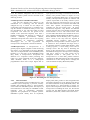
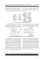
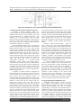
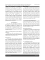
Ewunonu Toochi et al Int. Journal of Engineering Research and Applications ISSN : 2248-9622, Vol. 4, Issue 11(Version 3), November 2014, pp. 69-79 RESEARCH ARTICLE www.ijera.com OPEN ACCESS A Microcontroller Based Intrusion Detection System Ewunonu Toochi, Okwe Gerald Ibe, Iwuchukwu U.C,Uzuegbu C.J Department of, Electrical and Electronics Department, Federal University of Technology Owerri Imo State Nigeria ABSTRACT A Microcontroller based Intrusion Detection System is designed and implemented. Rampant, Okintrusion to restricted zones have highlighted the need for embedded systems that can effectively monitor, instantly alert personnel of any breach in security and retrieve graphic evidence of any such activity in the secured area. At the heart of the intrusion detection system is the PIC 168F77A Microcontroller that transmits pulses at 38 KHz. It is suitably interfaced to a GSM modem that can send SMS on sight of infringement and a webcam that can take snapshots. The report also presents the system software which has been developed in two parts: one in C++ Language using MPLAB KIT and the other written in AT COMMAND resident in the GSM modem. The system is very cost-effective, uses easily available components and is adaptable to control systems. Keywords: Microcontroller, Microprocessor, C++ language, Embedded system, intrusion detection I. Introduction In Africa today, especially Nigeria, there are contentions as to the effective functionality of National Security systems. Security is an encompassing phenomenon that is paramount to individuals, entities, communities and even nations. Security has to do with self-preservation which is the first law of existence. It implies a stable, relatively predictable environment in which an individual or group may pursue its ends or objectives without disruption, harm, danger or fear of disturbance or injury. A country’s national security is therefore concerned with the well-being, welfare and interest of her citizens. It is also concerned with the preservation of her sovereignty and territorial integrity against external aggression. The importance of security to the economic well-being of a country and her citizens was amply highlighted by a former American Secretary of Defense, Robert McNamara, when he stated that security is development and development is security. This means that, “without security there cannot be any development” (Guèhenno, 2004).The importance attached to security was well captured in the Nigerian Constitution of 1999: Section 14 (2) (b) where it is stated that: “The security and welfare of the people shall be the primary purpose of Government”. Invariably, the Constitution has saddled the Government with the responsibility of safeguarding lives, property and welfare of Nigerians against both internal and external threats including other forms of danger. However, everybody has a role to play at enhancing our National security as security is and should be everybody’s business. Security is both a prerequisite for and a critical aspect of development. At high levels of insecurity, development is www.ijera.com impossible; Economies fail, States go into negative economic growth; societies lose cohesion while health and education status drop (Paul, 2004). Security has become a very worrisome situation in our contemporary society. Items worth millions are reportedly lost or stolen regularly. People have become more aware of the unreliability of Government-provided security operatives. They are also aware that developed countries where technology-based Security systems are in use, suffer less loss than developing countries like Nigeria and many other African countries. II. Literature Review All Engineering products need Control Systems. Incorporating a computer within that product to undertake the control makes the entire system embedded. At the heart of embedded systems is a microprocessor chip or microcontroller chip. An embedded system could be said to be a computer system with a dedicated function within a larger mechanical or electrical system, often with real-time computing constraints (Heath, 2003; Barr, 2007). These devices are programmed to perform one or more tasks (Wilmshurst, 2007). It is embedded as part of a complete device that often has mechanical parts. Embedded system controls are in almost all the devices in common use today (Michael and Massa, 2006). Embedded systems are in existence almost everywhere: in our homes, offices, factories, hospitals, etc. They do not have, in most cases, general purpose devices such as hard drives, video controllers, printers and network cards. Embedded systems contain processing cores that are either microcontrollers or DSPs (Digital Signal Processors) (Giovino, 2008). Typical examples of systems with embedded system applications include the microwave 69 | P a g e Ewunonu Toochi et al Int. Journal of Engineering Research and Applications ISSN : 2248-9622, Vol. 4, Issue 11(Version 3), November 2014, pp. 69-79 oven, the domestic refrigerator and the electronic Ping-Pong. These systems will be reviewed in the following sections. 2.2 Microprocessors and Microcontrollers The past few decades have ushered in the introduction of a technology that has radically changed the way in which we can analyze our environment. The microprocessor or computer-on-achip first became a commercial reality in 1971 with the introduction of the 4-bit Intel 4004 by Intel Corporation. The 1970s saw the growth of the number of PC (Personal Computer) users from a handful of hobbyists and “hackers” to millions of business, industrial, governmental, defense, educational and private users who are now enjoying the advantages of inexpensive computing. Interestingly, one of the by-products of microprocessor development is the microcontroller. 2.2.1Microprocessors: A microprocessor is a general-purpose digital computer Central Processing Unit (CPU) on an integrated circuit chip (Kenneth, 1991). It is an important unit in the embedded system hardware. It is the heart of the embedded system (Raj, 2008). A microprocessor incorporates the functions of a computer's central processing unit (CPU) on a single integrated circuit (IC) (Osborne, 1980; Krishana, 2007). It is a multipurpose programmable device that accepts digital data as www.ijera.com input processes according to instructions stored in its memory and provides results as output. It is an example of sequential digital logic, as it has internal memory. Microprocessors operate on numbers and symbols represented in the binary numeral system. The first single-chip microprocessor was the 4-bit Intel 4004 released in 1971 with the Intel 8008 and other more capable microprocessors becoming available over the next several years., “TI (Texas Instruments) Engineers, Gary Boone and Michael Cochran were the first to successfully create the first microcontroller in 1971”. The result of their work was the TMS 1000 which went commercial in 1974. This combined a ROM (Read-Only Memory) unit, a RAM (Random Access Memory) unit, a processor and a clock on one chip and was targeted at embedded systems (Augarten, 1983). A block diagram of a microprocessor is shown in Figure 2.1. It contains an ALU (Arithmetic and Logic Unit), a PC (Program Counter), an SP (Stack Pointer), some working registers, a clock timing circuit and an interrupt circuit. The key term in describing the design of the microprocessor is “General-purpose”. The hardware design of a microprocessor is arranged such that a small or very large system can be configured around it. The prime use of a microprocessor is to fetch data, perform extensive calculations on that data and store the results of these calculations on a mass storage device or display the result for human use (Ray, Bhurchand, 2008). Figure 2.1: Block diagram of a microprocessor. 2.2.2 Microcontrollers A microcontroller can be considered to be a selfcontained system comprising a processor, memory modules and peripherals. Hence, a microcontroller can be used as an embedded system. The majority of microcontrollers in use today are embedded in other machinery such as automobiles, telephones, appliances and peripherals for computer systems. Embedded systems usually have no keyboards, www.ijera.com display units, disks, printers or other recognizable PC (Personal Computer) I/O vices and may lack devices for human interaction of any kind (Heath, 2003). The block diagram of a microcontroller in Figure 2.2 depicts and incorporates all the features found in a microprocessor including the ALU, PC, SP and the registers but has added features like ROM, RAM, Parallel I/O, Serial I/O, counters and a clock circuit. 70 | P a g e Ewunonu Toochi et al Int. Journal of Engineering Research and Applications ISSN : 2248-9622, Vol. 4, Issue 11(Version 3), November 2014, pp. 69-79 www.ijera.com Figure 2.2: Block Diagram of an 8-bit Microcontroller Thus, the main use of a microcontroller could be said to control the operations of a machine using a fixed program that is stored in the ROM. This does not change throughout the life time of the system. The microcontroller design uses a much more limited set of single-byte and double-byte instructions that are used to move the code and data from internal memory to the ALU. The instructions are coupled with pins on the IC (Integrated Circuit) package. These pins are “programmable” i.e. they are capable of having several different functions depending upon the wishes of the programmer (Kenneth, 1991). Explicitly, the microprocessor is concerned with rapid movement of code and data from external addresses to the chip, while the microcontroller is concerned with rapid movement of bits within the chip. The microcontroller can function as a computer with the addition of no external digital parts while the microprocessor must have many additional parts to be operated. The generic view of a microcontroller in Figure 2.3 shows that it contains a simple microprocessor core, along with necessary data and program memory to this which adds all the peripherals that allow it to do the interfacing. These include digital and analog input and output, or counting and timing elements. Like all other electronic circuits, the microcontroller needs power and requires a clock signal sometimes generated internally to drive the circuit. Figure 2.3: Generic view of a microcontroller www.ijera.com 2.2.3 Microcontroller Families There are thousands of different microcontroller types in the world today that are made by different manufacturers. A microcontroller family is built around a fixed microprocessor core. Different family members are then replicated by using the same core, with different combinations of peripherals and memory sizes. 2.2.4 PIC Microcontrollers PIC is a family of modified Harvard architecture microcontrollers made by Microchip Technology, derived from the PIC1650 originally developed by General Instrument's Microelectronics Division. The name PIC is referred to as “Peripheral Interface Controller" (General Instrument Databook, 1976). This was originally, a design of the company, General Instruments. PIC is popularly called Peripheral Interface Controller produced as PIC® in the 1970s by General Instruments as PIC® 1650 and 1655 processors (Wilmshurst, 2007). Its outstanding trademark qualities were simplicity, standalone, high speed and low cost. In many cases, they ran faster, required a simpler chipset and were quicker to prototype than their competitors. Moreover, Microchip stayed firmly entrenched in the 8-bit world. The ranges of PIC microcontrollers comprise different devices offered in different packages and for different applications. It should be noted that all PIC microcontrollers have these qualities in common: low cost, self-contained, 8 bits hardware structures, pipelining, RISC structure, single accumulator with fixed reset and interrupt vectors. Recently, Microchip has offered five (5) main families of microcontrollers as shown in the Table 2.1. Every member of any one family shares the same core architecture and instruction set. 2.2.9 The PIC 16F87XA The PIC 16F87XA generically has the 16F873A, 16F874A, 16F876A and 16F877A as family members. Table 2.1 above has summarized the features of this group. The 16F87XA is a unique group: two package sizes and two memory sizes are found. The package size is being driven by the 71 | P a g e Ewunonu Toochi et al Int. Journal of Engineering Research and Applications ISSN : 2248-9622, Vol. 4, Issue 11(Version 3), November 2014, pp. 69-79 number of I/O pins that are available. The 40-pin versions have five parallel digital (Input/output) as well as more analog inputs compared to their 28-pin counterparts. Thus, four group members are distinguished by their different memory sizes and different package sizes, while the larger package www.ijera.com allows more parallel Input/output ports to be used. The pin connection diagrams are illustrated in Figure 2.6. It is clearly shown that the “extra” pins on the larger devices are enclosed in a dotted line. The 874A/877A has port D and E which is a clear difference. Figure 2.6: Microcontroller pins (FASMICRO, 2013). Port D has 8 bits while port E has 3 bits. Either port can be used for general purpose I/O, like any of the other ports. The block diagram of port D, when configured for normal digital I/O, is shown (Figure 2.7a). An alternative function for port E is to provide three further analog inputs. So, port E is under the control of one of the registers that control the ADC, ADCONI. The setting of this determines whether the port is used for digital or analog signals. Figure 2.7: Block diagram of port D Pin driver circuit (Wilmshurst, 2007). Altogether, ports D and E can also form the parallel slave port. The ports are put into this mode by setting the PSPMODE bit in the TRISE register (Wilmshurst, 2007). This allows the microcontroller to interface as a slave to a data bus controlled by a microprocessor. The port E bits must be set as inputs (with digital mode selected in ADCONI); the state of TRIS D is, however, immaterial. Ports D and E are then configured as in Figure 2.8. The diagram shows 1 bit of port D, together with the three control lines: CS, WR and RD. These are the 3 bits of port E contained for this purpose. There is an output latch and an input latch for each port D bit. Illustratively, application for parallel slave port appears as in Figure 2.8, the port is connected to data bus and control lines www.ijera.com that form part of a larger system, controlled by a microprocessor. The 16F8744 program can write data to the port in which case bit OBF of TRISE is set. If CS and RD are taken low by the external circuit, then the port outputs the data held on its output latches onto the external bus. This action clears OB. If CS and WR are taken low, the port latches data from the bus into its input latches and bit IBF of TRISE is set.IBF is cleared when the port is read by the microcontroller program if the external circuit writes to the port again, before the previous word has been read, then the IBW bit of TRISE is set. The interrupt flag PSPIF is set when either a slave write or read is completed by the external circuit. 72 | P a g e Ewunonu Toochi et al Int. Journal of Engineering Research and Applications ISSN : 2248-9622, Vol. 4, Issue 11(Version 3), November 2014, pp. 69-79 www.ijera.com Figure 2.8: Parallel slave port connected to system bus (FASMICRO, 2013.) 2.3 Microcontroller Intrusion Detection Systems According to Hassan (Hassan, 2008), “An intrusion detection system can be defined as the tools, methods and resources to help identify, assess and report unauthorized or unapproved activity”. The efficiency of a security system could be highly improved with an improved number of measures put in place to avoid or detect intrusions. These measures may involve the use of several security networks monitored by a human or a machine. The environmental design refers to the physical structures and personnel’s put in place to monitor and handle physical threats to an area. Such include walls, security officials and security animals. The mechanical and electronic access control refers to the mechanical infrastructure put in place to prevent or disturb attacks. These include doors and locks. Intrusion detection deals with systems put into place to notify instantly obstructions especially at restricted zones. The final layer which is called the video/camera monitoring is a recorded image surveillance system which could range from a camcorder with a memory device to a hidden display unit and system. This provides a means of identifying the culprit in case the intruder is able to escape before a response team arrives. It is important to note that these layers should be able to function independently and also work as a unit. A number of systems could be integrated for intrusion detection to increasing the level of security in an enclosed area with the use of three or four of these security layers for optimum security. An Automated Intrusion Detection System incorporating an Alarm could be implemented in an enclosed area limited to rooms with only one entrance and exit. Such rooms include stores and vaults, thus all individuals accessing the room can only access the room and leave the room via one door. This makes keeping track of access information very convenient for the user. Hitherto, implementing the only first two layers of a good security system can make the rooms insecure and also very open to attacks from within thus the need for the automated intrusion detection system which will alert the human security of an ongoing attack via the means of an alarm system. Considering the environmental design which refers to www.ijera.com the physical structures and personnel’s put in place (such as security agencies and security dogs, a metal detector with electronic locks with identity validation systems) to monitor and handle physical threats to an area, can be employed. Intrusion detection deals with alarm systems put into place to alert security personnels and agencies when the first two stages are bypassed. (Oludele, Ayodele, Oladele & Olurotimi, 2009). Moreover, Microcontroller-based design of some systems like the burglar-alarm-displayingposition is an improvement in the electronics sector. Electronics like this device can be coupled solely via the use of discrete components, moreover the use of a microcontroller for this design can be justified by the reduction in the number of components used in the course of the design which also improves the reliability, durability and flexibility since burglar alarm systems are very imperative in the society, to solve the problem of accurate detection and location of intruders (Oshevire & Oladimeji, 2014). A vehicle compartment occupancy detection system is also operable to detect the presence of a person or animal within a vehicle compartment, such as a vehicle cabin or trunk space, by detecting a change in an electric field within the compartment. The detection system includes an electric field generator and an electric field sensor which is operable to detect changes in the electric field generated within the compartment. The detection system may be operable in response to one or more inputs which are indicative of a hazardous condition within the vehicle compartment (McCarthy, 2004). 2.4 Programming the Embedded System Embedded system design is made up of two main aspects: the hardware and the software. Embedded system programs are written to run on the target’s system hardware. The idea of computer programming is to recognize each instrument from a computer set and execute its instruction set especially those in the binary called machine code. In other words, the human nature learns the machine code of the computer exactly as the computer would read it. A computer program, (compiler /interpreter) then converts that program into a machine code that the 73 | P a g e Ewunonu Toochi et al Int. Journal of Engineering Research and Applications ISSN : 2248-9622, Vol. 4, Issue 11(Version 3), November 2014, pp. 69-79 computer can comprehend. An assembler is introduced, in that every one of the computer’s instructions set is given a mnemonic i.e. a three- orfour-letter word that can be used to represent directly one instruction from the instruction set. The programmer then writes the program using the instruction mnemonics. A special computer program called a cross-assembler, usually running on a PC, converts the code written in mnemonics to the machine code that the computer will see (Wilmshurst, 2001). In the early days, programming was done in assembly language to program almost any type of computer. This helps us to directly work with the resources of the computer efficient code that executes quickly. Working in assembly language helps us to learn the structure of the computer although rather slow, error prone and does not always produce well-structured programs. III. Methodology The model and methodology, considerations/ specifications of the intrusion detection system and its functional components are reported. The development stages and modes of operation of the software application developed for the hardware, was also reported here. A summarized version of the user’s manual for the system as well as strategies and plan for testing of the components of the system concludes the chapter. 3.1 Review of existing Detection Systems and their Limitations Several means, ways and systems have been employed to checkmate intrusions both in developed and developing nations. Some of these systems and methods will be reviewed in this section. Electrical Locks Electric locks come in many forms. The most basic is a Magnetic Lock (commonly called a Mag lock). A large electro-magnet is mounted on the door frame and a corresponding armature is mounted on the door. When the magnet is powered and the door is closed, the armature is held fast to the magnet. Mag locks are simple to install and are very attackresistant. But mag locks are also problematic. Improperly installed or maintained mag locks have fallen on people. In other words, one must unlock the mag lock to both enter and leave. This has caused fire marshals to impose strict codes on the use of mag locks and the access control practice in general. Other problems include a lag time in as the collapsing magnetic field is not instantaneous. This lag time can cause a user to walk into the door. Mag locks by design fail unlocked, that is if power is removed they unlock. This could be a problem where security is a prime concern (Oludele et al., 2009). www.ijera.com www.ijera.com Electric Strikes They replace a standard strike mounted on the door frame and receive the latch and latch bolt. Electric strikes can be simple to install when they are designed for drop-in replacement of a standard strike. But some electric strikes require that the door frame be heavily modified. Electric strikes allow mechanical free egress: As a user leaves, he operates the lockset in the door, not the electric strike in the door frame. Electric strikes can also be either fail unlocked, as a mag lock, or the more secure fail locked. Electric strikes are easier to attack than a mag lock. It is simple to lever the door open at the strike. Often, there is an increased gap between the strike and the door latch (Oludele et al., 2009) Electric Mortise and Cylindrical Locks These are drop-in replacements for the door mounted mechanical locks. A hole must be drilled in the door for electric power wires. Also a power transfer hinge is used to get the power from the door frame to the door. Electric mortise and cylindrical locks allow mechanical free egress. Electric mortise and cylindrical locks can be either failed unlocked or fail locked. (Oludele et al., 2009) Electrified Exit Hardware Electric field exit Hardware sometimes called panic hardware or crash bars, are used in fire exit applications. The idea is that one simply pushes against the bar to open it, making it the easiest of mechanically free exit methods. Electrified exit hardware can be either failed unlocked or fail locked. A drawback of electrified exit hardware is their complexity which requires skill to install and maintenance to assure proper function. Motor Operated Locks are used throughout Europe. An European motor operated lock has two modes, day mode where only the latch is electrically operated, and night mode where the more secure deadbolt is electrically operated (Wikipedia, 2009). User Authentication Systems When implemented with a digital access system, one of the following access systems or digital authentications systems can be with an electric lock. These however are only a few of the numerous authentication devices available; Numerical Codes, Passwords and Passphrases. Perhaps the most prevalent form of electronic lock is that using a numerical code for authentication, the correct code must be entered in order for the lock to deactivate. Such locks typically provide a keypad, and some feature an audible response to each press. Combination lengths are usually between 4 and 6 digits long. A variation on this design involves the user entering the correct password or pass phrase. A major hindrance however is the fact that users are 74 | P a g e Ewunonu Toochi et al Int. Journal of Engineering Research and Applications ISSN : 2248-9622, Vol. 4, Issue 11(Version 3), November 2014, pp. 69-79 capable of forgetting their codes. Forgetfulness is especially common in older people and this system will not be convenient for them. These codes are, in some cases, easy to crack. Security Tokens Another means of authenticating users is to require them to scan or "swipe" a security token such as a smart card to have a link between the token and the lock. For example, some locks can access stored credentials on a personal digital assistant using infrared data transfer methods. However, just as in the case of an ATM card, the magnetic tape tends to wear off with time either resulting to time wasting in accessing a room or the inability of the user to access the room at all. Lack of Intrusion Detection Alerts All intrusion alerts are dependent on discovery by individuals i.e. either security personnel’s or students. This delay gives the culprit enough time to dispose of whatever has been stolen and more than enough time to cover his tracks. This leads to a string of an ever increasing number of unsolved cases of theft. A proper intrusion detection system alerts the responsible quarters once an abnormality is discovered in the system. Inefficient Monitoring Method Monitoring one’s belongings are left to the vigilance on the part of the security officials and the owners of such goods. This can prove to be ineffective considering the fact that as human beings, we tend to get bored performing monotonous tasks. This leads to the search of more exciting tasks no matter how irrelevant they might be at such times. There is also the need to take occasional breaks to refresh one. A very observant thief will be able to use such minute details to his advantage. When surveillance is continuous with no visible break, it tends to deter the less desperate thieves and thereby reducing the theft rate. Choice of “C ++” as a Programming Language For some time in recent past, C++ has overwhelmingly become the language of embedded programmers. “C++” has thrived precisely in the range of projects for both 8- bit and 64- bit processors, in systems with bytes, kilobytes and megabytes of memory. It is simpler to learn, and compilers are available for almost all its processors in use. It has processor independence that allows programmers to concentrate on algorithms and applications rather than on the details of particular processor architecture. The greatest strength of C++ is that it is a very “low level” language that gives embedded programmers an extra ordinary degree of direct hardware control without sacrificing the www.ijera.com www.ijera.com benefit of high level languages (Van Sickle, 2003). Its low level nature is a clear intention of the language’s creators (Wilmshurst, 2001). C++ is an object-oriented superset of C that has spread widely amongst embedded programmers. It has almost all the core features of C but adds new functionalities for better data abstractions and a more object-oriented style of programming. Certainly, C has become the centerpiece of embedded programming and everything said about C equally applies to C++. Choice of MPLAB IDE kit as a design tool This is a Windows development environment specifically made for PIC microcontroller. It has all the tools used to design and deploy embedded systems. Figure 3.14 depicts a Prototype MPLAB PIC Development Kit. Advantages abounds using MPLAB KIT for designing and maintaining embedded systems. Some of these advantages especially those relating to its choice in the design of this project include: Ease and speed in building and compiling projects. This is very much evident because its User Interface allows for simultaneous designing, coding and debugging. It allows for dynamic features to be added to the environment. Its interface allows the designer to quickly build a project and then refine/repair it in coding view. MPLAB KIT is customizable. The designer can easily set preferences controlling how and to what extent accessibility is coded. The code, fonts, colour, highlighting modes etc with which to preview a page can be adjusted. Choice of AT COMMAND as a Communication Language “AT” command was developed by AT&T Wireless systems communication for effective communication between a DCE (fax) and a DTE (computer). It is popularly referred to as AT command because every of its syntax starts with the letters AT. Simcom Wireless (Simcom Wireless, 2010), in their publications, made clear the numerous merits of AT COMMAND. It was stated that it was the best open source communication link between a DCE and DTE. Also, it was stated that AT COMMAND offers excellent performance, portability, reliability and can be learnt with relative ease. It also offered an improvement to data integrity and is more searchable and allows for concurrent users. 3.4 Flow Chart Description Figure 3.0 is the operational flow chart which shows the overall description of how the entire system works. 75 | P a g e Ewunonu Toochi et al Int. Journal of Engineering Research and Applications ISSN : 2248-9622, Vol. 4, Issue 11(Version 3), November 2014, pp. 69-79 www.ijera.com Fig 3.0 System operational Flowchart 3.5 System Block Diagram Figure 3.1: Block Diagram of Intrusion Detection System www.ijera.com 76 | P a g e Ewunonu Toochi et al Int. Journal of Engineering Research and Applications ISSN : 2248-9622, Vol. 4, Issue 11(Version 3), November 2014, pp. 69-79 3.6 Intrusion Detection System Block Diagram Description The entire circuit consists of different blocks or sub-units with each block performing an essential function. The sub-units are interconnected to give the complete system. The different blocks that make up the system are described in details below. www.ijera.com 3.6.1 Power Supply Sub-Unit Every electronic system requires ac power supply to work. The quantity of voltage and current required by each component is specified in its datasheet. Most electronic components and sub systems operate on +5V. This voltage (+5V) is a basis for electronics power supply. The datasheet of the components used in the intrusion detection system also specify a power supply voltage of +5V except for that of the relay which works with +12V. Figure 3.2 shows the power supply sub-unit and its various components. Figure 3.2: Power supply sub-unit The 7805 is a 5V regulator which ensures an output of +5V and it is connected to the microcontroller. The LM317 is a variable regulator. Its output voltage is varied by varying the 5KΩ variable resistor until the desired voltage is gotten. In this circuit, it is used to provide the needed +12V for the relay power supply. The four diodes, D1 to D4, rectify the ac voltage from the transformer to dc voltage. The capacitor, C1, smoothens\filters the rectified voltage so as to remove ripples. The Transformer, TR1, steps down the ac voltage from 220V ac to 15V ac. 3.6.2 The Microcontroller This is the heart of the Intrusion detection system. The PIC16F877A microcontroller is used. Its presence minimizes component count required to get the circuit working. It also authenticates the device as an embedded electronic system. The pins in the microcontroller are grouped into ports. Hence, we have PORTA, PORTB etc. Figure 3.3 shows the arrangement of a 40-pin PIC 16F877A microcontroller. www.ijera.com Figure 3.3: PIC I6F877A microcontroller 3.6.8 Intrusion Detection System Circuit Diagram The various sub-units discussed were combined to realize the complete circuit diagram shown in Figure 3.12. 77 | P a g e Ewunonu Toochi et al Int. Journal of Engineering Research and Applications ISSN : 2248-9622, Vol. 4, Issue 11(Version 3), November 2014, pp. 69-79 www.ijera.com R1 U1:A 8 2.2k D1 R2 47k R3 3 D2 R4 100k 1 LED R5 100k 100k 2 4 1N4148 TL393 U2 13 14 RL1 D3 1N4001 Q1 2 3 4 5 6 7 8 9 10 R6 1 2.2k BC547 OSC1/CLKIN OSC2/CLKOUT RB0/INT RB1 RB2 RA0/AN0 RB3/PGM RA1/AN1 RB4 RA2/AN2/VREF-/CVREF RB5 RA3/AN3/VREF+ RB6/PGC RA4/T0CKI/C1OUT RB7/PGD RA5/AN4/SS/C2OUT RC0/T1OSO/T1CKI RE0/AN5/RD RC1/T1OSI/CCP2 RE1/AN6/WR RC2/CCP1 RE2/AN7/CS RC3/SCK/SCL RC4/SDI/SDA MCLR/Vpp/THV RC5/SDO RC6/TX/CK RC7/RX/DT RD0/PSP0 RD1/PSP1 RD2/PSP2 RD3/PSP3 RD4/PSP4 RD5/PSP5 RD6/PSP6 RD7/PSP7 RL1 D3 1N4001 33 34 35 36 37 38 39 40 D4 D5 D6 15 16 17 18 23 24 25 26 C2 1 19 20 21 22 27 28 29 30 11 12 10 9 1uF U3 3 C1+ C1- T1IN R1OUT T2IN R2OUT T1OUT R1IN T2OUT R2IN C2+ C2- VS+ VS- PIC16F877A J1 14 13 7 8 2 6 CONN-D9F Q1 4 R7 2.2k 5 MAX232 7 8 9 10 11 12 13 14 D0 D1 D2 D3 D4 D5 D6 D7 4 5 6 RS RW E 1 2 3 1uF VSS VDD VEE BC547 C1 1 6 2 7 3 8 4 9 5 LCD LM016L Figure 3.12: Complete circuit diagram The interconnections of the various components form the complete circuit diagram which was used to achieve our access control. When powered on, the LED power indicator flashes or comes ON. The PIC 16F877A Microcontroller transmits and receives infrared pulses at 38 KHz at no line of sight infringement and obstructions. As the Camera USB cable is connected to a laptop, the camera software is run. The LCD, LED and microcontroller are interfaced to inform the user on the situation report. Subsequently, the buttons instantly switches ON the camera to enable the webcam take snapshots and save the pictures. V. Conclusion In the future, many homes and offices will rely on the Intrusion Detection System as a means of effective monitoring and guarding of restricted areas like armory divisions, bank strong rooms, etc. where only authorized personnel can be granted access. They can also be employed to detect theft, leakage of examination papers and instant reporting of situations at hand especially when the personnel in charge are absent. REFERENCES [1] IV. RESULTS AND DISCUSSIONS The prototype were designed and implemented. The results obtained from the combination of various intrusion detection system components and corresponding constructions are evaluated and some observation were made during the different stages of testing. Some distances were taken so as to ascertain the workability of the intrusion detection system. The best line-of-sight is about 100cm the distance from the transmitter to the receiver. See the picture of the completed prototype in fig 4.1 [2] [3] [4] [5] Figure 4.1: Front view of the completed work showing the picture of a lady that was detected on the visual display unit www.ijera.com Augarten, S. (1983). The Most Widely Used Computer on a Chip: The TMS 1000"State of the Art: A Photographic History of the Integrated Circuit (New Haven and New York: Ticknor & Fields). ISBN 0-89919-195-9. Retrieved 2009-1223.FASMICRO, (2013). Embedded Systems Overviews. First Atlantic Semiconductors & Micro Electronics, Owerri.Giovino, B. (2013). "Micro Controller.com – Embedded Systems supersite". Hassan, M.F (2008). Intelligent Intrusion Detection System Blog. Retrieved, October, 14 2008. Hayat Khiyal, M., Khan, A., & Shehzadi, E. (2009). SMS Based Wireless Home Appliance Control System for Automating Appliances and Security. Issues in Informing Science and Information Technology, Volume 6, 2009. Heath, S. (2003). Embedded systems design. EDN series for design engineers (2 Ed.). Newness. p. 2. ISBN 978-0-7506-5546-0 78 | P a g e Ewunonu Toochi et al Int. Journal of Engineering Research and Applications ISSN : 2248-9622, Vol. 4, Issue 11(Version 3), November 2014, pp. 69-79 [6] [7] [8] [9] [10] [11] [12] [13] [14] [15] [16] [17] [18] Intel 8084, (2008). Oral History on the development and promotion of INTEL 8084 Microcontroller, Computer History Museum Oral History, 2008. p. 4. Retrieved 2011-June- 28 Jean-Marie, G. (2005). Giving Peace a Chance, in the World in 2005 (London: The Economist, 2004), p. 3; Human Security Report 2004 (London: Oxford University Press, forthcoming). Kenneth, A. (1991). The 8051 Microcontroller, West publishing Company, St Paul, USA. Krishna, K. (2007). Microprocessors and Microcontrollers: Architecture Programming And System Design PHI Learning Pvt. Ltd., 2007 ISBN 81-2033191-5 page 61, Luo, R.C., Min-Hsiung, Chou, Y.T., Liao, C.T., & Lai, C.C. (2007). An Intelligent Security Robot System; Industrial Electronics Society, 2007. IECON 2007, 33rd Annual Conference of the IEEE. 5-8 Nov. 2007. McCarthy, C.K (2004). Vehicle compartment occupancy detection system: US 6768420, B2USPTO, USPTO Assignment, Espacenet. [19] [20] [21] [22] www.ijera.com Incidence Of Civil War, Center for the Study of African Economics, Department of Economics, Oxford University, Copenhagen Challenge Paper, April 23, 2004, p. 22. Raj, K. (2008). Embedded Systems Architecture, Programming and Design. Tata McGraw-Hill. p. 5. ISBN 978-0-07066764-8. Ray, A.K. & Bhurchand, K.M., (2008). Advanced Microprocessors and Peripherals. India: Tata McGraw-Hill. Van Sickle, E. (2003). Programming Microcontrollers in C, 2nd Ed Elsevier, USA. ISBN 1-878767-57 Wilmshurst, T. (2007). Designining Embedded systems with PIC Microcontrollers, Elsevener Ltd, USA. Michael, B. (2007). Embedded Systems Glossary. Neutrino Technical Library. Retrieved 2007-04-21 Michael, B. & Anthony, J. M. (2006). Introduction Programming embedded systems: With C and GNU development tools. O'Reilly. pp. 1–2. ISBN 978-0-59600983-0 Microchip Technology, Inc. (2007), PIC18F1220/1320 Data Sheet, retrieved 2012-04-02 MOSDATA, (1976). General Instrument, 1976 Data book. Oludele, A., Ayodele, O., Oladele, O., &Olurotimi, S. (2009). Design of an Automated Intrusion Detection System incorporating an Alarm: Journal of Computing, volume 1, issue 1,December 2009, ISSN: 2151-9617. Oshevire, P., & Oladimeji, T. (2014). Design and implementation of a MicroController based burglar Alarm: Journal of Advancement in Engineering and Technology, http://scienceq.org/Journals/ JAET.php Received: January 15, 2013; accepted: January28, 2014, published: January 31, 2014. Paul, C. & Anke, H. (2004). The Challenges of Reducing the Global www.ijera.com 79 | P a g e