1
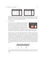
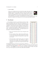
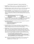
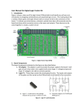
CPSC 121: Models of Computation
The Magic Box User’s Manual
Patrice Belleville, Mark Greenstreet, Anthony Winstanley
Copyright (C) 2003 The University of British Columbia
The Magic Box User’s Manual
2
Our purpose in creating this lab kit is to give you an opportunity to experience some of the fun
things that you can build as a Computer Scientist. You will get to turn the mathematical principles
learned in class into real, working projects that perform simple computations. Real circuits require
a power source, inputs, and outputs. Rather than make you build all of this from scratch, your kit
includes a “Magic Box” circuit board. This board accepts 9-volt power from the included wallplug adapter and provides the 5 volts required by the integrated circuit logic chips in your kit. It
also contains eight switches to provide inputs to your designs, and eight LEDs (coloured lights) to
display their outputs. The purpose of this manual is to explain how to use the various parts of your
lab kit.
1 Equipment
1.1 Parts List
The kit as you first receive it should contain:
• “The Magic Box” circuit board (see page 4)
• a breadboard (see page 7)
• a wiring kit
• a 9V power supply
• a 5V power wire
The following will be available in the lab:
• “Chips”: integrated circuits (ICs) in dual inline packages (DIPs) (see the appendix for specific
circuit information).
• more wire
1.2 Practical Hints
Here are a few tips to help you maintain your kit in excellent condition, so you (or someone else
you might have sold it to) can continue using it even after the course is over.
• Everything in your kit operates at safe, low voltages. About the only way you could get a
shock (unpleasant but not harmful) would be by putting into your mouth the plug from the
9-volt wall-plug adapter, or the wires from the 5-volt power cable. Please don’t do this.
The Magic Box User’s Manual
3
• The Magic box includes a voltage regulator that converts the 9-volt power from the walladapter to the 5-volt power required by the chips. This is the part sticking out of the board
along the top just to the left of the UBC CPSC label. The metal clip on this part is called a
heat sink. It helps cool off the voltage regulator, which can sometimes get fairly hot if your
circuit is using a lot of chips. You should avoid touching it (you will not get serious burns,
but it might be slightly unpleasant).
• When you insert or remove wires from your Magic Box, be careful not to break the ends off
in the contact points (holes). There will be pliers in the lab to help you remove broken wire
ends, but it is best if you don’t have to use them.
• When you insert or remove chips from your breadboard, be careful not to bend the leads (the
chip’s “legs”). When inserting a chip, make sure that the leads of the chip are lined up with
the contact holes in the breadboard, and then push down applying even pressure on the chip.
To remove the chip, pry it gently from both ends at the same time.
• Make sure that you connect power and ground properly to your chips, as explained in your
first lab (see also the appendix). If you reverse these wires, you can damage the chip. In fact,
other than bending pins or hitting them with a hammer, this is about the only way you can
damage one of these chips.
• When you are wiring your circuit or making changes, it is a good idea to disconnect the 9volt wall-plug adapter from the MagicBox. This will prevent you from damaging chips if you
make a wiring error.
• The contact points on the circuit board will be stiff initially; once they have had a wire inserted
into them once or twice, they will be much easier to use.
2 Description
Let us start by learning about the various parts of the Magic Box. The Magic Box will provide the
power, switches, and LEDs. Wires will connect these to the circuits that we will implement on the
breadboard.
Find the Magic Box logo. Position the Magic Box so the logo reads left to right and is the right
way up:
The Magic Box User’s Manual
4
We will call this the standard orientation. In the remainder of this manual, we will always refer
to locations on the board with respect to this orientation.
2.1 The components of the Magic Box
Most of your Magic Box consists of circuits that allow its inputs and outputs to perform the tasks
that we will claim they perform. Thus, the only components that you will need to be concerned
about are:
The Magic Box User’s Manual
5
• 8 switches
The MagicBox provides eight switches that you can use as inputs to your circuits. These switches are located in the lower
left corner of the MagicBox circuit board, and the white arrows on the circuit board show which contact point is controlled by which switch. Each switch is set by its white plastic rocker. If the top half of the rocker (by the numbers 1 2 3
. . . 8) is pushed down, then the contact point for that switch
will be driven to a logical high level (5 volts). If the bottom half of the rocker is pushed down (along the edge of the
switch-assembly with the word “open”) then the contact point for that switch will be driven
to a logical low level (0 volts).”
• 8 probes
The eight probes allow you to display outputs from your
circuit and to observe signals within your design. They are
very helpful for debugging. The probes are near the middle
of the MagicBox circuit board, on the left half. The white
arrows on the circuit board show which LED is controlled
by which contact point. If the contact point is connected
to a signal that is driven to a logical low level, then the
corresponding LED will be off (dark). If the contact point
is connected to a signal that is driven to a logical high level,
then the LED will be on (lit).
To assist with debugging, the probes are made so that they
will blink if they aren’t connected to a valid logic signal.
Thus, any unused probes will blink. More importantly, if you probe a chip input that isn’t
connected to an output, or to power, or to ground, then the LED will blink. When an input
is not connected to anything, the behaviour of the chip is not defined. Chips do not assume
that unconnected inputs are low! By blinking, these probes can help you to quickly identify
this common error.
Note that this behaviour (blinking) can be turned off via the switch next to the three clock
generator switches (see below). The switch is labeled ”Blink”, and the probes will blink only
when the top half of the rocker is down. Otherwise, their default behaviour will be off.
Each set of four LEDs is also connected to a numeric display. These display values in hexadecimal (base 16) as shown in the table below, where we use L for “low” and “H” for “high”:
The Magic Box User’s Manual
D1
L
L
L
L
L
D2
L
L
L
L
H
6
D3
L
L
H
H
L
D4
L
H
L
H
L
Digit
0
1
2
3
4
D1
L
L
L
H
H
D2
H
H
H
L
L
D3
L
H
H
L
L
D4
H
L
H
L
H
Digit
5
6
7
8
9
Note that the displays will show arbitrary patterns for the four combinations of D1, D2, D3
and D4 that we have not shown here (instead of the letter A through F that those of you who
already know about hexadecimal might have expected). The display connected to the LEDs
labeled D5, D6, D7 and D8 behaves in the same way.
• A clock generator
Later in this class, you will implement circuits that compute
sequences of results. A special signal called a clock controls
these calculations. Each time the clock goes from low-tohigh, your circuit will perform one more step of its calculation. This is just like the clock in your computer. For example, if you have a computer with a 2.4GHz clock, that means
that it performs 2 400 000 000 steps each second. For our
labs, the clock will be much slower. You can either select a manual clock, where your circuit
will perform one step each time you push a button, or a clock generated by the MagicBox.
The clock generator is on the right half of the MagicBox circuit board, about one-third of
the way down from the top. There, you will find a set of four switches, a push-button, and a
strip of four contact points. The last three of the four switches (switch2, switch3 and switch4)
control the operation of the clock generator. The second switch from the left (switch2) selects
whether the clock is generated automatically or by the manual push-button. If you set that
switch so that the top half of the rocker is down, then the clock is generated by the push button.
The clock output will be low while the button is not pushed and go high when you push the
button. If you set that switch so that the bottom half of the rocker is down, then the clock
is generated automatically by the MagicBox. When the clock is generated automatically,
the two rightmost switches (switch3 and switch4) set the clock speed according to the table
below:
switch3
L
L
H
H
switch4
L
H
L
H
clock-frequency
1 kHz
2 Hz
1 Hz
0.7 Hz
The clock signal is output on the strip of four contact points above and to the left of the
switches. All four contact points are connected to the clock signal: you may use any or all of
them.
The Magic Box User’s Manual
7
• A power supply
There are two connectors for power located in the upper right corner of the
MagicBox circuit board. The upper connector receives power from the 9-volt
wall-plug adapter. Just plug the cord from the adapter into this connector
when you are using the board. The lower connector provides 5-volts for use
on the breadboard. The 5-volt power cable plugs into this connector: the red
wire from this cable provides the +5 volts and the black wire provides ground (0 volts). Note
that the two connectors are of different sizes so you can not get the cables mixed up.
3 Breadboard
The breadboard is the part of your kit that you will use to plug
chips in, and connect them to each other and to the Magic Box. Position the breadboard so the letters a through j are lined up from left
to right at the top and the bottom. We will refer to this as the standard
orientation. You will notice that the breadboard is divided into two
halves by a space that runs down its length from top to bottom (the
gutter). All chips will be plugged in so half of their leads are in column e, and the other half are in column f . The little holes that cover
the board are connected in the following way:
• There are no connections from one side of the gutter to the
other side.
• The outer columns of holes, labeled with red and blue lines,
are reserved for power and ground, respectively. All holes
in each of these columns are connected to each other from
top to bottom.
• All the other holes, on each side of the gutter, are connected
in rows from left to right. This means that if a signal is
coming into one of the holes, then it runs horizontally and
will transfer to any other wires connected to holes in that
same row.
The integrated circuits in your lab kit can really only be damaged if
you switch their connections to power and ground. Therefore, we will reserve two colours of wire
to help prevent this from happening. Red wire is always (and only) connected to power, which (in
our case) is +5 Volts. Black wire is always (and only) connected to ground. (0 Volts). Every other
wire in your circuit (signal wires) will be colours other than red and black.
The Magic Box User’s Manual
8
4 ICs
The little rectangular pieces of plastic with metal pins coming out of the sides are integrated circuits,
also called ICs or chips. Each of these contains a little piece of silicon that does the actual logical
function, plus the plastic and wires so you can make connections to it. This section describes how
to identify the different chips in your kit.
The chips in your kit come from a standardized selection of logic parts known as the 7400
(pronounced ”seventy-four hundred”) series. The form for a part number is MM74LSNNP where:
• MM is a code that identifies the company that manufactured the chip.
• LS indicates that the chip uses the LS (”Low-power Schottky”) parts. Over the years, many
variations of the 7400 series have been made. We use the LS variation because they are easy
to use and hard to damage.
• NN indicates the logical function of the part (see the appendix starting on page 10). For
example, a 74LS04 contains six gates that compute logical negation (a low input produces a
high output and vice-versa), while a 74LS08 contains four two-input AND gates (the output
is high if both inputs are high, and low otherwise).
• P is the kind of packaging used. The parts in our kit usually have “N” (for plastic, dual-inline).
4.1 Orientation
Normally, a small notch is carved in the top of one end of a chip to designate pin numbering, and
pins are numbered counter-clockwise from pin 1:
16
15
14
13
12
11
10
9
1
2
3
4
5
6
7
8
Note that real chips will not have the counter-clockwise arrow drawn on the diagram. Most 14 pin
chips have ground on pin 7 and power on pin 14, while most 16 pin chips have ground on pin 8 and
power on pin 16. Therefore, chips should be plugged into the board with pin 1 at the top left corner
(assuming the breadboard is in standard orientation). The 5-volt power cable should be connected
to the board with the red wire connected to the red row to the right of the gutter, and the black wire
connected to the blue to the left of the gutter. Connections to power and ground should go to these
power and ground rows, and nowhere else.
The Magic Box User’s Manual
9
4.2 Insertion
You should turn off the power before you insert or remove an IC. Use uniform pressure across the
top of the IC when inserting it into the breadboard: This will prevent the pins from bending. You
may have to adjust the distance between the two rows of pins before insertion. To remove ICs from
the breadboard, slide an IC chip extractor under the body of the chip in the center gutter of the
breadboard and pull gently. If a chip extractor is unavailable, carefully use your fingers to pull the
chip straight out without bending any pins.
The Magic Box User’s Manual
10
Appendices
A
74LS* Reference
74LS00 Quad 2-Input NAND Gate
All four NAND gates may be used independently.
On any one gate, when either input is low the output is driven high. If both inputs are high the output is low.
74LS02 Quad 2-Input NOR Gate
All four NOR gates may be used independently.
On any one gate, with either input high the output
is low. When both inputs are low the output is
high. Note that the gates do not use the pins the
same way as the gates in the 74LS00 do.
74LS04 Hex Inverter
All six inverters may be used independently. On
any one inverter, the low-input condition drives
the output high. The high-input condition drives
the output low.
The Magic Box User’s Manual
74LS08 Quad 2-Input AND Gate
All four AND gates may be used independently.
On any one gate, when either input is low, the output is low. When both inputs are high the output
is high.
74LS10 Triple 3-Input NAND Gate
All three NAND gates may be used independently. On any one gate, when any input is low,
the output is driven to a high state. When all three
inputs are high, the output is driven to a low state.
74LS11 Triple 3-Input AND Gate
All three AND gates may be used independently.
On any one gate, when any input is low, the output
is driven to a low state. When all three inputs are
high, the output is driven to a high state.
11
The Magic Box User’s Manual
74LS20 Dual 4-Input NAND Gate
Both 4-input gates may be used independently.
On either gate, any input-low condition drives the
output high. When all inputs are high, the output
is low.
74LS21 Dual 4-Input AND Gate
Both 4-input gates may be used independently.
On either gate, any input-low condition drives the
output low. When all inputs are high, the output
is high.
74LS27 Triple 3-Input NOR Gate
All three NOR gates may be used independently.
On any one gate, when any input is high, the output is driven to a low state. When all three inputs
are low, the output is driven to a high state.
12
The Magic Box User’s Manual
74LS32 Quad 2-Input OR Gate
All four OR gates may be used independently. On
any one gate, when either input is high, the output is driven high. When both inputs are low the
output is low.
74LS83 4-Bit Full Adder
This is an arithmetic unit that provides the sum of
two 4-bit binary numbers and an input carry C0 as
follows:
C0
+
A4 A3 A2 A1
+
B4 B3 B2 B1
= C4 Σ 4 Σ 3 Σ 2 Σ 1
Note the unusual location of the power and ground
pins.
74LS86 Quad Exclusive-OR Gate
The package contains four independent
EXCLUSIVE-OR gates. They may be used
separately. On any one gate, when one, but not
both, inputs are high, the output is high. When
both inputs are high or both inputs are low, the
output is low.
13
The Magic Box User’s Manual
14
74LS139 2→4 Decoder
The chip contains two individual decoders. Each decoder drives one line according to the binary value
at its address. Note that the outputs uses low for 1
and high for 0 (contrarily to most other chips).
INPUTS
ENABLE ADDRESS
B
A
H
X
X
L
L
L
L
L
H
L
H
L
L
H
H
OUTPUTS
0
H
L
H
H
H
1
H
H
L
H
H
2
H
H
H
L
H
3
H
H
H
H
L
This circuit can also be used to make a 3→8 decoder: connect A0 to B0 and A1 to B1 : these become the A0 and A1 of the new 3-bit input. Then
connect the new input A2 to one of the ENABLE
inputs, and also connect it to the other ENABLE input through an inverter, as shown in the figure.
+5V
16
G
1
15
14
13
H
B0
B1 X4
A0
2
A1 X0
3
4
12
11
10
9
X5 X6 X7
X1 X2
6
5
X3
7
8
12
10
9
A2
74LS153 Dual 1-of-4 Multiplexer
This devices contains two multiplexers (A and B).
If an Enable input is high, the corresponding output
will be low, regardless of the input data. If an Enable
input is low, then the device selects between four
inputs (X0 through X3), according to the values of
S0 and S1, to drive the output (Z). Note that both
multiplexers use the same S0 and S1, and hence will
select the same of their inputs.
+5V
16
EA
1
13
15
14
EB
S0 X3B X2B X1B X0B ZB
11
S1 X3A X2A X1A X0A ZA
7
3
6
5
2
4
8
The Magic Box User’s Manual
15
74LS157 Quad 1-of-2 Multiplexer
This device selects (SELECT) between two inputs
(A and B) to drive the output (OUT). All four of
the switches are simultaneously enabled or selected.
If the Enable input is high, all outputs will be low,
regardless of the input data. If the Enable input is
low, and the Select input is low, the A inputs will
provide an output. If the Enable input is low, and
the Select input is high, the B inputs will provide an
output. For instance, you can use it to
• Select between two independent inputs.
• Wrap a 74LS157 around a 74LS175 to make a latch that loads a new value on a rising clock
edge when SELECT is high, and keeps its old value when SELECT is low.
74LS175 Quad ”D” Memory
There are four separate storage latches, each with
normal and complementary output. All latches are
simultaneously updated. Information at the D inputs is entered into the latches on the ground-to-high
(positive edge) of the clock command. The only
time that information is entered into this package
is on the positive edge of the clock. The Clear input is normally held high. Bringing it to ground will
clear the memory, making all Q outputs low and all
Q outputs high. This is a fully clocked system and
can be used as a shift-register element. Stages can
be cascaded.
The Magic Box User’s Manual
16
74LS670 4x4 Register File
The register file is organized as 4 words of 4 bits
each and separate on-chip decoding is provided for
addressing the four word locations to either write-in
or retrieve data. This permits simultaneous writing
into one location and reading from another word location. Four data inputs are available which are used
to supply the 4-bit word to be stored. Location of
the word is determined by the write-address inputs
A and B in conjunction with a write-enable signal.
Data applied at the inputs should be in its true form. That is, if a high-level signal is desired
from the output, a high-level is applied at the data input for that particular bit location. The latch
inputs are arranged so that new data will be accepted only if both internal address gate inputs are
high. When this condition exists, data at the D input is transferred to the latch output. When the
write-enable input is high, the data inputs are inhibited and their levels can cause no change in the
information stored in the internal latches. When the read-enable input is high, the data outputs are
inhibited and go into the high-impedance state. (Tri-state, see Bebop) The individual address lines
permit direct acquisition of data stored in any four of the latches. Four individual decoding gates
are used to complete the address for reading a word. When the read address is made in conjunction
with the read-enable signal, the word appears at the four outputs.
1
Most of this information was taken from ”The TTL Cookbook” by Don Lancaster, as published by SAMS in 1974.
The rest was taken from ”The TTL Data Book” as written and published by Texas Instruments.
The Magic Box User’s Manual
17
B Test Procedure
Making sure The Magic Box works:
1. Test probe points (LEDs and 7-segment displays)
(a) Ensure that there are no wires connected to The Magic Box.
(b) Ensure all 4 control switches (SW2) are closed and all 8 data switches (SW1) are open.
(c) Plug The Magic Box into its power supply (+9V).
All the LEDs should be blinking together, and the 7-segment displays should be blinking
’0’ together.
(d) Using a length of wire, connect the output of data switch 8 to the first LED (D1).
LED D1 should turn off.
(e) Repeat step (1d) with all LEDs (D1 through D8).
Each LED should turn off in turn.
(f) Close data switch 8 and repeat steps (1d) and (1e).
The LEDs should turn on this time instead of off.
(g) Disconnect test wire and open control switch 1. (Blink)
All the LEDs should turn off, and the 7-segment displays should read ’0’.
2. Test switches
(a) Connect the output of data switch 7 to the first LED (D1) using wire.
LED D1 should be off.
(b) Close data switch 7.
LED D1 should turn on.
(c) Repeat steps (2a) and (2b) with data switches 6 down to 1.
3. Test clock
(a) Use the test wire to connect Clock Output to one of the LEDs.
(b) Push the Manual Clock button a few times
The LED should be on whenever the button is down, and off otherwise.
(c) Open control switch 2 (M.Clk)
The LED should be blinking slowly.
(d) Open control switch 4.
The LED should be blinking a little faster.
(e) Open control switch 3 and close control switch 4.
The LED should be blinking a little faster yet.
(f) Open control switch 4.
The LED should be blinking so fast you can’t tell it’s blinking. It will just look a little
dimmer than usual.
The Magic Box User’s Manual
C
18
Schematic
1M
100K
LM339
1M
74LS04 or
74LS00
−
+
330
1M
ClkP
1M
x4
74LS47
330
a
A0
b
A1
c
A2
d
A3
100K
74LS175
D Q
e
ClkD
Q’
f
x2
g
x8
ClkD
NE556
74LS00
680K
1M
2.2M
out
ClkP
discharge
1M
2.2M
trigger
100K
74LS175
threshold
D Q
ClkD
47nF
Q’
NE556
74LS157
out
51K
discharge
MUX
s
680K
trigger
100K
threshold
74LS175
D Q
ClkD
1nF
470nF
Q’
1uF
100K
74LS175
D Q
ClkD
Q’