1
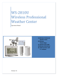
Instruction Manual
DC: 100214
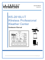
WS-2816U-IT
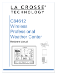
Wireless Professional
Weather Center
Hardware Manual
1|Page
INTRODUCTION
Congratulations on purchasing this state-of-the-art weather station. Featuring time, date, weather
forecast, wind gust and wind speed, indoor/outdoor temperature and humidity, air pressure and rainfall,
this weather station will provide various weather information and weather forecasts.
Monitor and record a variety of data collected by the weather station including both indoor and external
values sampled by the various weather station sensors.
The system works as a stand-alone Weather Station or a Remote Monitoring Weather Station when using
the included La Crosse Alerts Gateway.* There is no app or software to install.
All remote monitoring is done on www.lacrossealerts.com with an account that you create if you wish to
use these added features.*
Online information at: www.lacrossetechnology.com/support
CONTENTS
Introduction.................................................................................................................................... 2
Inventory of Contents .................................................................................................................. 5
Features ......................................................................................................................................... 6
Weather Station WS-2816U-IT ............................................................................................... 6
Wireless Thermo-hygro Sensor (TX59UN-1-IT) .................................................................. 7
Wireless Solar Powered Wind Sensor (TX63U-IT) ............................................................. 7
Wireless Self Emptying Rain Sensor (TX58UN-IT)............................................................. 7
Optional Gateway For Remote Monitoring ........................................................................... 7
Setup Instructions Step-by-Step ................................................................................................ 7
Function Buttons........................................................................................................................... 8
Set button ................................................................................................................................... 9
▲/DATE button ......................................................................................................................... 9
▼/RAIN button .......................................................................................................................... 9
Alarm button .............................................................................................................................. 9
MIN/MAX button........................................................................................................................ 9
LCD Screen ................................................................................................................................. 10
Program Menu ............................................................................................................................ 10
LCD contrast set ..................................................................................................................... 10
Manual Time set ..................................................................................................................... 11
12/24 hour time display.......................................................................................................... 11
Date set .................................................................................................................................... 11
°F/°C temperature unit ........................................................................................................... 11
Wind speed unit ...................................................................................................................... 11
Rainfall unit .............................................................................................................................. 12
Relative air pressure unit ....................................................................................................... 12
Relative pressure reference value ....................................................................................... 12
Weather tendency sensitivity ................................................................................................ 12
Storm Warning Sensitivity ..................................................................................................... 12
Model WS-2816U-IT
www.lacrossetechnology.com/support
P a g e |2
Storm Alarm on/ off set .......................................................................................................... 13
Wind direction display type ................................................................................................... 13
Factory reset procedures ...................................................................................................... 13
To exit the manual setting mode .......................................................................................... 14
Weather Alarm Operations for the Weather Station Display ............................................... 14
The following weather alarms can be set in alarm mode ................................................. 14
Default weather alarm value ................................................................................................. 15
Pressure alarms ...................................................................................................................... 15
Indoor temperature alarms: ................................................................................................... 15
Indoor humidity alarms: ......................................................................................................... 15
Outdoor temperature alarms:................................................................................................ 16
Outdoor humidity alarms: ...................................................................................................... 16
Wind gust alarm ...................................................................................................................... 17
Wind direction alarm .............................................................................................................. 17
24 Hour rainfall alarm ............................................................................................................. 17
Hysteresis .................................................................................................................................... 18
Display Modes ............................................................................................................................ 18
Mode 1...................................................................................................................................... 18
Mode 2...................................................................................................................................... 18
Date or seconds display ........................................................................................................ 18
Rainfall Display ....................................................................................................................... 18
Weather Forecast and Tendency ............................................................................................ 19
Weather forecasting icons ..................................................................................................... 19
Weather tendency indicator .................................................................................................. 19
Air Pressure History Graph ....................................................................................................... 20
Wind Direction and Wind Speed Measurement .................................................................... 20
Rainfall Measurement................................................................................................................ 21
MIN/MAX Weather Data ............................................................................................................ 21
Reset the MIN/MAX weather data ....................................................................................... 21
Reset Total rainfall amount ................................................................................................... 21
Common Terms .......................................................................................................................... 22
Relative Humidity .................................................................................................................... 22
Wind Chill-Equivalent Temperature ..................................................................................... 22
Wind Gust ................................................................................................................................ 22
Mounting and Placement of Sensors and Weather Station ................................................ 22
Wind sensor ............................................................................................................................. 23
Rain sensor.............................................................................................................................. 24
Thermo-hygro sensor ............................................................................................................. 24
Model WS-2816U-IT
www.lacrossetechnology.com/support
P a g e |3
Weather Station ...................................................................................................................... 24
Gateway ................................................................................................................................... 25
Stand-alone Weather Station or Internet Connected Weather Station with Remote
Monitoring & Alerts ..................................................................................................................... 25
Specifications .............................................................................................................................. 26
Indoor temperature ................................................................................................................. 26
Indoor humidity........................................................................................................................ 26
Outdoor temperature .............................................................................................................. 26
Outdoor humidity .................................................................................................................... 26
Wind speed/ gust .................................................................................................................... 26
Wind chill .................................................................................................................................. 26
Rainfall...................................................................................................................................... 26
Outdoor data reception Interval ............................................................................................ 26
Air pressure ............................................................................................................................. 26
Transmission range ................................................................................................................ 26
Power consumption ................................................................................................................ 26
Weather Center ................................................................................................................... 26
Thermo-hygro transmitter .................................................................................................. 27
Rain sensor .......................................................................................................................... 27
Wind sensor ......................................................................................................................... 27
Gateway ............................................................................................................................... 27
Dimensions .............................................................................................................................. 27
Weather Center ................................................................................................................... 27
Thermo-hygro transmitter .................................................................................................. 27
Rain sensor .......................................................................................................................... 27
Wind sensor ......................................................................................................................... 27
Gateway ............................................................................................................................... 27
Care and Maintenance .............................................................................................................. 27
Alerts and Monitoring Disclaimer ............................................................................................. 28
Liability Disclaimer ..................................................................................................................... 28
Warranty Information ................................................................................................................. 28
FCC Statement ........................................................................................................................... 29
Model WS-2816U-IT
www.lacrossetechnology.com/support
P a g e |4
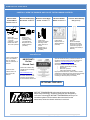
INVENTORY OF CONTENT S
CAREFULLY OPEN THE PACKAGE AND LOCATE THE FOLLOWING CONTENTS:
Wireless Solar
Powered Wind
Sensor TX63U-IT
1.
2.
3.
4.
5.
6.
Wireless Self-Emptying
Rain Sensor TX58UN-IT
1.
Mast holder
Right angle adaptor
1 x U-bolts
2 Washers + 2 Nuts
2.
Plastic Reset Rod
100% solar-powered
Base sensor,
funnel top cover
and battery cover
(pre-assembled)
Requires two “AA”
Alkaline batteries
(included)
Wireless Thermo-Hygro
Sensor TX59UN-1-IT
1.
2.
3.
4.
5.
Airflow cover
Wall mount adapter
Mounting screws
Plastic anchors for
screws
Requires two “C”
Alkaline batteries
(included)
Wireless Weather
Station WS-2816U-IT
1.
2.
Remote Monitoring & Alerts Account
Activation Card
All items, including Wind
Sensor, are Protected
under U.S. Patents:
5,978,738; 6,076,044; &
6,597,990
Wind Sensor also
Protected under U.S.
Patent: 6,761,065;
RE42,057
IMPORTANT!!
Do Not
Discard Card:
Contains the Activation Key
to enable remote monitoring
and alerts on
www.lacrossealerts.com.
Please file activation key for
your future records if you do
not wish to use the Internet
connected features at this time.
Foldout stand
Requires three “C”
Alkaline batteries
(included)
La Crosse Alerts Gateway
Set (Optional)
1.
2.
3.
Gateway
20-volt A/C Adapter
Ethernet (LAN) cable:
Connects your network
router with high-speed
Internet (not included) to
Gateway
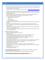
Remote Monitoring & Text/E-mail Alerts
Optional Remote Monitoring & Text/E-mail Alerts are
included to remotely monitor your home & backyard
weather on www.lacrossealerts.com from your
smartphone, tablet or computer.*
Set & receive custom e-mail & text alerts:*
o
Outdoor temperature & humidity
o
Wind & rain
o
Barometric pressure
o
Indoor temperature & humidity
High-speed Internet access, network router & Internetenabled device with web browser required (not included)
E-mail account and/or SMS text ability for remote
monitoring & alerts required (not included)
OPTIONAL FEATURES
INSTANT TRANSMISSION is the state-of-the-art new wireless
transmission technology, exclusively designed and developed by
La Crosse Technology®. INSTANT TRANSMISSION offers you an
immediate update of all the outdoor data measured from the
transmitters; follow the climatic variations in real-time!
Model WS-2816U-IT
www.lacrossetechnology.com/support
P a g e |5
FEATURES
W EATHER STATION W S-2816U-IT
1. (OPTION 1 ) Stand-alone weather station with wireless backyard weather sensors. Included Gateway
Set and Activation Card is not required.
Wireless weather station information and manual are available at: www.lacrossetechnology.com/2816
2. (OPTION 2) Internet-connected weather station with remote monitoring and alerts uses the included
Gateway Set and Activation Card to enable the included Remote Monitoring & Text/E-mail Alerts from
www.lacrossealerts.com
3. Remote Monitoring & Text/E-mail Alerts are included to remotely monitor your home & backyard
weather on www.lacrossealerts.com using your smartphone, tablet or computer.*
4. Set & receive custom e-mail & text alerts for:*
Outdoor temperature & humidity
Wind & rain
Barometric pressure
Indoor temperature & humidity
5. High-speed Internet access, network router & Internet-enabled device with web browser required (not
included)
6. E-mail account and/or SMS text ability for remote monitoring & alerts required (not included)
Connect the gateway to your router (not included) with the LAN cable, for wireless connection to the
weather station.
Note: See the included Activation Card for the activation key to enable remote monitoring and alerts.*
There is no app. or software to install.
All remote monitoring is done on www.lacrossealerts.com with an account that you create if you wish
to use these added features.*
Weather station without a computer
• 12/24 hr. time & calendar with date, month & year
• Manual time setting
• Forecast with tendency based on barometric pressure: sunny, partly cloudy & stormy
• Indoor temperature with min/max time & date: 41°F to 104°F (5°C to 40°C)
• Outdoor temperature with min/max time & date: -40°F to 139.8°F (-40°C to 59.9°C)
• In/out relative humidity with min/max time & date: 3% to 99% RH
• Wind chill: down to -40°F (-40°C)
• Relative air pressure with 24hr. / 72hr. history graph (inHg / hPa): Preset range 27.10 to 31.90 inHg
• Wind speed with min/max time & date: 0 to 111 mph (km/h, m/s, knots & Beaufort scale)
• Wind direction with compass (16 points / 22.5 degrees)
• Wind gust with max time & date
• Rainfall for last hour, 24hr., week, month & total: 0 to 393.7 inches (0 to 9999.9 mm)
• Weather alarms for temperature, humidity, wind gust/direction, pressure, 24hr. rain & storm warning
(Weather Station)
• LCD contrast setting for easy viewing
• Wall hanging or free standing
The Professional Weather Station can be used as a stand-alone system. No software is required to
connect the outdoor sensors to the display.
Wireless Weather Station Information & Manuals: www.lacrossetechnology.com/support.
Weather station with a computer and Internet connection (optional)
• Internet time/date sync available when using gateway and Internet connection
Model WS-2816U-IT
www.lacrossetechnology.com/support
P a g e |6
Follow the instructions on www.lacrossealerts.com to set up the gateway and register the display. All
website connections are browser-based. Condensed system requirements: Windows Internet Browser:
IE8 or later, Chrome 12 or later, Firefox 12 or later; or Mac OS X 10.6 (or later): Safari 5 or later.
W IRELESS THERMO-HYGRO SENSOR (TX59UN-1-IT)
Monitors backyard temperature and humidity
Transmission of temperature and humidity data
200 ft. wireless range (free of obstructions) to weather station
2 "C" Alkaline batteries (included)
W IRELESS SOLAR POW ERED W IND SENSOR (TX63U-IT)
Monitors backyard wind speed, direction and gust
100% solar-powered (built-in power cell, no batteries necessary)
High-efficiency solar panels maintain operation in every season
200 Ft. wireless range (free of obstructions) to thermo-hygro sensor
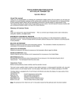
W IRELESS SELF EMPTYI NG RAIN SENSOR (TX58UN-IT)
Monitors backyard rainfall
200 ft. wireless range (free of obstructions) to thermo-hygro sensor
2 "AA" Alkaline batteries (included)
OPTIONAL GATEW AY FOR REMOTE MONITORING
200 ft. wireless range (free of obstructions) to weather station
20-volt A/C power cord
Ethernet cable
Includes Gateway, AC adapter & LAN cable
Internet access, network router and web browser (not included)
Included Remote Monitoring & Text / Email Alerts (Optional)
Remotely monitor home & backyard weather from your smartphone, tablet or computer:*
Outdoor temperature & humidity
Wind& rain
Barometric pressure
Indoor temperature & humidity
Set & receive weather alerts via e-mail & text message.*
*High speed Internet access, network router, & web browser (not included) required. Text messaging
may require vendor service fees per message (consult the terms of your device’s message plan).
Monitoring & Alerts Activation with Online Instructions: www.lacrossealerts.com
SETUP INSTRUCTIONS STEP-BY-STEP
IMPORTANT: Make sure to observe the correct polarity when inserting batteries. The "+" markings on the
batteries must line up with the diagrams inside the battery compartments. Inserting the batteries
incorrectly may result in permanent damage to the units. During the initial setup process, place the
wireless weather station and the outdoor sensors on a surface with 5-10 feet between each sensor and
the weather station. Only use Alkaline batteries, rechargeable batteries may not work.
Model WS-2816U-IT
www.lacrossetechnology.com/support
P a g e |7
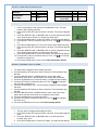
STEP 1: Complete initial setup on a table with all components within 10 feet of each other.
STEP 2:
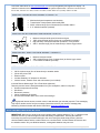
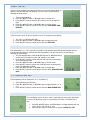
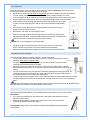
It is important to allow sufficient light to reach the solar panel while activating the wind sensor. Make
sure the lights are on in the setup room and the solar panel is facing a 60W light bulb or brighter.
Ensure the solar panel is not covered, and then remove the black protective foil on the solar panel.
Remove the tape covering the reset hole.
Use the provided plastic reset rod to gently press the reset button once in the hole on the bottom of
the sensor.
Press Reset Button on
Bottom of Wind Sensor
(Solar Panel Must Face
Light)
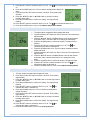
STEP 3: Insert two "AA" size batteries into rain sensor with correct polarity.
STEP 4:
Insert two "C" size batteries into the thermo-hygro sensor with the correct polarity.
Note: Allow all sensors to run for two minutes before inserting batteries in the weather station.
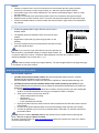
STEP 5:
Insert three "C" size batteries into the wireless weather station with the correct polarity.
Note: Every time the wireless weather station receives data from the
sensors, the wireless icons will blink once and then return to solid if the last
transmission was successful. A wind speed or rainfall amount that reads "0"
does not mean reception failure. It means that there was no wind or rain at the
time of the last measurement. The thermo-hygro sensor syncs with the wind
and rain sensors and sends all outdoor sensor data to the weather station. The
thermo-hygro sensor tries for 4 minutes to sync to the wind sensor and then 4
minutes for the rain sensor. If not successful within 4 minutes, the thermohygro sensor will stop looking for the other sensors.
Wait 10 minutes for reception from all sensors before setting time and date or mounting sensors
outside.
STEP 6: Set Time and Date. See “Program Menu” below.
Setup Troubleshooting: If the sensor data fails to display for any of the outdoor sensors within 10
minutes (“- - -“are displayed), remove the batteries from all units for 1 minute and start the Setup
procedure again at Step 1.
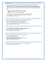
FUNCTION BUTTONS
Model WS-2816U-IT
www.lacrossetechnology.com/support
P a g e |8
SET BUTTON
Hold for 3 seconds to enter the SET mode, where the following can be changed: LCD contrast,
Manual time setting, 12/24 hour time display, Date setting, °F/°C temperature unit, Wind speed unit,
Rainfall unit, Pressure unit, Relative pressure reference setting, Weather tendency threshold setting,
Storm warning threshold setting, Storm Alarm On/ Off setting, Wind direction display type and Factory
reset
Press to toggle between the display of Mode 1 or Mode 2:
o Mode 1: "Wind speed + 24 hr. pressure history graph"
o Mode 2: "Gust + 72 hr. pressure history graph"
In the weather alarm setting mode, press to switch the weather alarm On/Off
In the weather alarm setting mode, hold to adjust the weather alarm value
Stop the weather alarm when ringing
▲/DATE BUTTON
Press to toggle between the display of seconds or date in the time display
Press to increase the level of different settings in SET mode
Hold to re-learn the thermo-hygro sensor synchronization
Press to reset the MIN/MAX record when in MIN/MAX display mode
Stop the weather alarm when ringing
▼/RAIN BUTTON
Press to switch the rainfall display mode: Total, 1h, 24h, week, month
Press to decrease the level of different settings in SET mode
Hold to synchronize the display with the gateway
Stop the weather alarm when ringing
ALARM BUTTON
Press to enter the time alarm and weather alarm setting mode
Confirm particular alarm setting
Press to exit the manual setting mode
Stop the alarm when the time alarm or weather alarm rings
Press to exit MIN/MAX record display mode
Stop the weather alarm when ringing
MIN/MAX BUTTON
Press to display minimum and maximum records of various weather data
Stop the weather alarm when ringing
Model WS-2816U-IT
www.lacrossetechnology.com/support
P a g e |9
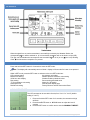
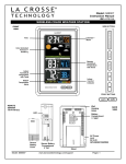
LCD SCREEN
When the signal from an outdoor transmitter is successfully received by the Weather Station, the
corresponding icon will be switched on. (If not successful, the icon will not be shown on the LCD).
The user can see whether the last reception was successful ( icon is on) or not ( icon is off). Blinking
of the icon shows that a reception is in process.
PROGRAM MENU
Press and hold the SET button for 3 seconds to enter the SET mode.
Note: The display will automatically return to Mode 1 display in 30 seconds if a button is not pressed.
While in SET mode, press the SET button to advance to the next SET mode item:
LCD contrast setting
Air pressure unit setting
Manual time setting
Relative pressure reference value setting
12/24 hour time display
Weather tendency threshold value
Date setting
Storm warning threshold value
°F/°C temperature unit setting
Alarm On / Off setting
Wind speed unit
Wind direction display type
Rainfall unit setting
Factory Reset or Internet Connection Reset
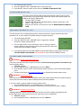
LCD CONTRAST SET
The LCD contrast can be set within 8 levels; from "Lcd 1" to "Lcd 8" (default
setting is "Lcd 5"):
1. Press and hold the SET button for 3 seconds; the contrast level digit
will flash.
2. Press the ▲/DATE button or ▼/RAIN button to adjust the level of
contrast.
3. Press the SET button to confirm and to enter the MANUAL TIME SET.
Model WS-2816U-IT
www.lacrossetechnology.com/support
P a g e | 10
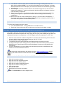
MANUAL TIME SET
The time will be updated automatically with the time from the Internet when the
display is synchronized with the gateway. The time can be set manually by
following the steps below.
1. The hour digit will flash.
2. Press the ▲/DATE button or ▼/RAIN button to set the hour.
3. Press the SET button to switch to the minutes. The minute digit will
flash.
4. Press the ▲/DATE button or ▼/RAIN button to set the minute.
5. Press the SET button to confirm and to enter the 12/24-HOUR TIME
DISPLAY.
12/24 HOUR TIME DISPLAY
The time can be set as 12-hour or 24-hour format. To change the time display:
1. The "12h" or "24h" digits will flash.
2. Press the ▲/DATE button or ▼/RAIN button to toggle the value.
3. Press the SET button to confirm and to enter the DATE SET.
DATE SET
The default date is 1.1. of the year 2013. The date will be updated automatically with the date from the
Internet when the display is synchronized with the gateway. The date can also be set manually by
following the steps below.
1. The year digit will flash. Press the ▲/DATE button or ▼/RAIN button to
set the year. The range runs from "00" (2000) to "99" (2099).
2. Press the SET button to confirm the year and enter the month setting.
The month digit will flash.
3. Press the ▲/DATE button or ▼/RAIN button to set the month.
4. Press the SET button to confirm the month and enter the date setting
mode. The date digit will flash.
5. Press the ▲/DATE button or ▼/RAIN button to set the date.
6. Press the SET button to confirm and to enter the °F/°C TEMPERATURE
UNIT.
°F/°C TEMPERATURE UNIT
The temperature can be displayed in °F or °C (Default °F).
1. The temperature unit will flash.
2. Press the ▲/DATE button or ▼/RAIN button to toggle between “°F” or
“°C”.
3. Press the SET button to confirm and to enter the WIND SPEED UNIT.
W IND SPEED UNIT
The wind speed unit can be set to read in mph (miles per hour), km/h (kilometers
per hour), bft (Beaufort), knots or m/s (meters per second). The default unit is
mph.
1. Press the ▲/DATE button or ▼/RAIN button to toggle between the unit
“mph”, “km/h”, "bft", "knots" or “m/s”
2. Press the SET button to confirm and to enter the RAINFALL UNIT.
Model WS-2816U-IT
www.lacrossetechnology.com/support
P a g e | 11
RAINFALL UNIT
The rainfall unit can be set to read in inch or mm. The default unit is inch.
1. Press the ▲/DATE button or ▼/RAIN button to toggle between the unit
“inch” or “mm”
2. Press the SET button to confirm and to enter the RELATIVE AIR
PRESSURE UNIT.
RELATIVE AIR PRESSUR E UNIT
The relative air pressure can be set to read in inHg (inches of mercury) or hPa
(hectopascal). The default unit is inHg.
1. Press the ▲/DATE button or ▼/RAIN button to toggle between the unit
“inHg" or “hPa”
2. Press the SET button to confirm and to enter the RELATIVE
PRESSURE REFERENCE VALUE SET.
RELATIVE PRESSURE REFERENCE VALUE
Note: For an exact measurement, it is necessary to adjust the barometer to the local relative
air pressure (related to elevation above sea level). Ask for the current air pressure of the home area
(local weather service, the World Wide Web, calibrated instruments in public
buildings, airport). The default reference pressure value is 29.91 inHg.
The relative air pressure can be manually set to another value within the range
of 27.17 to 31.90 inHg (920 to 1080 hPa) for a better reference.
1. The current relative pressure value will flash.
2. Press the ▲/DATE button or ▼/RAIN button to increase or decrease the value. Continually
holding the button will allow the value to increase faster.
3. Press the SET button to confirm and enter the WEATHER TENDENCY SENSITIVITY.
W EATHER TENDENCY SENSITIVITY
The sensitivity of the weather forecast icons to changes in air pressure can be set manually. Smaller
values result in a more sensitive forecast. The switching sensitivity value can be set to .06, .09 or .12
inHg (2, 3 or 4 hPa). Select lower values (.06) for high humidity areas like the coastline. Select high
numbers (.12) for dry areas like the desert. The default value is 0.09 inHg.
1.
2.
3.
The sensitivity value will flash.
Press the ▲/DATE or ▼/RAIN to select the value.
Press the SET button to confirm and to enter the STORM WARNING
SENSITIVITY.
STORM W ARNING SENSITIVITY
A storm warning is displayed by flashing of the down weather tendency arrow
when the air pressure decreases a specified amount over six hours. The
sensitivity value for the storm warning display can be set between .09 inHg to
.27 inHg (3hPa to 9hPa). The default value is 0.15 inHg.
Model WS-2816U-IT
www.lacrossetechnology.com/support
P a g e | 12
1. The sensitivity value will flash.
2. Press the ▲/DATE button or ▼/RAIN button to select the value.
3. Press the SET button to confirm and to enter the STORM ALARM ON/OFF SET.
STORM ALARM ON/ OFF SET
The storm warning display (flashing downward weather tendency arrow) can be
accompanied by a ring of the alarm. Switch the acoustic storm warning alarm On
(AON) or Off (AOFF) (Default OFF).
1. The digit "AOFF" will flash.
2. Press the ▲/DATE button or ▼/RAIN button to switch the alarm On or Off.
("AOFF" = Off; "AON" = On)
3. Press the SET button to confirm and to enter the WIND DIRECTION DISPLAY
TYPE.
W IND DIRECTION DISPL AY TYPE
The wind direction can be displayed using either compass directions or degree measurements. N is
equivalent to 0° on the compass. The default setting is compass directions.
1. The wind direction will flash.
2. Press the ▲/DATE button or ▼/RAIN button to toggle from compass
directions to degree measurements.
3. The next steps in SET mode is the factory reset, so unless you wish to
reset the display to factory defaults, simply wait until the SET mode times
out and returns to the Mode 1 display.
4. If you wish to perform a FACTORY RESET, press the SET button to confirm and to enter the
FACTORY RESET PROCEDURE. SEE WARNINGS in the FACTORY RESET section.
FACTORY RESET PROCEDURES
WARNING: Internet Connection Reset Only
The factory reset procedure has an option to clear the remote monitoring registration information only
from the weather station.
1. "rES oFF" will flash.
2. Use the ▲/DATE button or ▼/RAIN button to select "rES Lo".
3. Press the SET button to confirm and the weather station will return to the normal weather display
mode.
4. Follow the instructions at www.lacrossealerts.com to reregister the weather station online.
WARNING: Avoid Factory Reset
Performing a factory reset will erase all MIN/MAX values and weather data stored in the display's internal
memory and return the weather station’s settings back to the factory defaults.
If you do not wish to reset the display to factory defaults, either:
Press the MIN/MAX button or the ALARM button to exit SET mode, or
Simply wait 30 seconds until the SET mode times out and returns to the Mode 1 display.
WARNING: Complete Factory Reset
A factory reset will erase the Internet connection and the connection between the display and the
thermo-hygro sensor and require the all sensor connections to be re-established.
5. "rES oFF" will flash.
6. Use the ▲/DATE button or ▼/RAIN button to select "rES ALL".
Model WS-2816U-IT
www.lacrossetechnology.com/support
P a g e | 13
7. Press the SET button to confirm and a countdown timer will begin counting down from "127"
When the timer displays "dOnE", you must remove the batteries from the display for 10 minutes.
While the batteries are out of the display, also remove the batteries from the thermo-hygro sensor
and rain sensor.
8. After waiting for 10 minutes, insert the batteries into the thermo-hygro sensor, and rain sensor
making sure to align the "+" symbol on the batteries with the markings on the battery cover and
inside the battery compartment.
9. Within 2 minutes of inserting the batteries into the sensors, insert the batteries into the display,
making sure to align the "+" symbol on the batteries with the markings inside the battery
compartment.
10. Wait 5 minutes for the outdoor weather data to display. If any of the outdoor data displays "--"
after waiting for 5 minutes, follow the "Setup Instructions" near the beginning of this manual or
in the Quick Setup Manual included with the product.
TO EXIT THE MANUAL S ETTING MODE
To exit the manual setting at any time, either:
Press the MIN/MAX button or the ALARM button to exit SET mode or
Simply wait 30 seconds until the SET mode times out and returns to the Mode 1 display.
WEATHER ALARM OPERATIONS FOR THE WEATHER ST ATION DISPLAY
The Weather alarms can be set when certain weather conditions are met. For example, you can set the
thresholds for the outdoor temperature to +104°F (high) and 14°F (low), while enabling the high alarm and
disabling the low alarm (i.e. temperatures <14°F won’t trigger alarm, but temperatures >+104°F will).
When the value meets the condition for high alarm or low alarm, the alarm will ring for 2 minutes and
the value will blink, along with the corresponding icon ("HI AL"/ "LO AL").
Press any button to stop a ringing alarm.
The high and low alarms can be switched On/Off independently, according to the need.
If at any time during the alarm setting process you would like to exit alarm setting mode, press the
MIN/MAX button or wait for about 30 seconds and the display will return to normal display mode
automatically.
Press the ALARM button to enter ALARM mode. Subsequent presses of the ALARM button will
advance to the next weather alarm section.
Note: Monitoring & Alerts Activation with Online Instructions: www.lacrossealerts.com. Remote
Monitoring and Alerts Activation Card has instructions and the needed activation key to enable this
feature.
THE FOLLOW ING W EATHER ALARMS CAN BE SET IN ALARM MODE
High and Low pressure alarms
High and Low indoor temperature alarms
High and Low indoor humidity alarms
High and Low outdoor temperature alarms
High and Low outdoor humidity alarms
High wind gust alarm
Wind direction alarm
Rainfall amount in 24 hour period alarm
Note: The storm alarm is set in the program menu.
Model WS-2816U-IT
www.lacrossetechnology.com/support
P a g e | 14
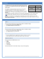
DEFAULT W EATHER ALAR M VALUE
Pressure
Temperature
(In or Out)
Low
High
Low
High
28.35 inHg
30.71 inHg
32F
104F
Wind Gust
Wind Direction
Rainfall in 24 hours
Relative Humidity
(In or Out)
High
North
High
Low
High
62.0mph
1.96 in
45%
70%
PRESSURE ALARMS
1. In the normal display mode, press the ALARM button once. The highpressure alarm display will show.
2. Press and hold the SET button for about 2 seconds. The pressure digit will
flash.
3. Press the ▲/DATE button or ▼/RAIN button to set the high-pressure alarm
value. Hold the arrow button in to change the value faster.
4. Press the ALARM button to confirm the setting. The digit will stop flashing.
5. Press the SET button to switch the alarm on or off. The
icon indicates the alarm is switched
on.
6. Press the ALARM button once. The Low Pressure alarm display will show.
7. Press and hold the SET button for about 2 seconds. The pressure digit will
flash.
8. Press the ▲/DATE button or ▼/RAIN button to set the low-pressure alarm
value. Hold the arrow button in to change the value faster.
9. Press the ALARM button to confirm the setting. The digit will stop flashing.
10. Press the SET button to switch the alarm on or off. The
icon indicates
the alarm is switched on.
11. Press the ALARM button to move to the indoor temperature alarms.
INDOOR TEMPERATURE ALARMS:
1. The high indoor temperature alarm display will show.
2. Press and hold the SET button for about 2 seconds. The temperature digit
will flash.
3. Press the ▲/DATE button or ▼/RAIN button to set the high indoor
temperature alarm value. Hold the button in to change the value faster.
4. Press the ALARM button to confirm the setting. The digit will stop flashing.
5. Press the SET button to switch the alarm on or off. The
icon indicates
that the alarm is switched on.
6. Press the ALARM button once. The low outdoor temperature alarm display
will show.
7. Press and hold the SET button for about 2 seconds. The temperature digit
will flash.
8. Press the ▲/DATE button or ▼/RAIN button to set the low indoor temp
alarm value. Hold the arrow button in to change the value faster.
9. Press the ALARM button to confirm the setting.
10. Press the SET button to switch the alarm on or off. The
icon indicates
the alarm is on.
11. Press the ALARM button to move to the indoor humidity alarms.
INDOOR HUMIDITY ALAR MS:
1. The high indoor humidity alarm display will show.
2. Press and hold the SET button for about 2 seconds. The humidity digit will
flash.
3. Press the ▲/DATE button or ▼/RAIN button to set the high indoor
humidity alarm value.
4. Press the ALARM button to confirm the setting. The digit will stop flashing.
Model WS-2816U-IT
www.lacrossetechnology.com/support
P a g e | 15
5. Press the SET button to switch the alarm on or off. The
icon indicates the alarm is switched
on.
6. Press the ALARM button once. The low indoor humidity alarm display will
show.
7. Press and hold the SET button for about 2 seconds. The humidity digit
will flash.
8. Press the ▲/DATE button or ▼/RAIN button to set the low indoor
humidity alarm value.
9. Press the ALARM button to confirm the setting. The digit will stop
flashing.
10. Press the SET button to switch the alarm on or off. The
icon indicates the alarm is on.
11. Press the ALARM button to move to the outdoor temperature alarms.
OUTDOOR TEMPERATURE ALARMS:
1. The high outdoor temperature alarm display will show.
2. Press and hold the SET button for about 2 seconds. The temperature
digit will flash.
3. Press the ▲/DATE button or ▼/RAIN button to set the high outdoor
temp alarm value. Hold the button in to change the value faster.
4. Press the ALARM button to confirm the setting. The digit will stop
flashing.
5. Press the SET button to switch the alarm on or off. The
icon
indicates that the alarm is switched on.
6. Press the ALARM button once. The low outdoor temperature alarm
display will show.
7. Press and hold the SET button for about 2 seconds. The temperature
digit will flash.
8. Press the ▲/DATE button or ▼/RAIN button to set the low outdoor
temp alarm value. Hold the arrow button in to change the value
faster.
9. Press the ALARM button to confirm the setting. The digit will flash.
10. Press the SET button to switch the alarm on or off. The
icon
indicates the alarm is switched on.
11. Press the ALARM button to move to the outdoor humidity alarms.
OUTDOOR HUMIDITY ALA RMS:
1. The high outdoor humidity alarm display will show.
2. Press and hold the SET button for about 2 seconds. The humidity
digit will flash.
3. Press the ▲/DATE button or ▼/RAIN button to set the high outdoor
humidity alarm value.
4. Press the ALARM button to confirm the setting. The digit will stop
flashing.
5. Press the SET button to switch the alarm on or off. The
icon
indicates the alarm is switched on.
6. Press the ALARM button once. The low outdoor humidity alarm
display will show.
7. Press and hold the SET button for about 2 seconds. The humidity
digit will flash.
8. Press the ▲/DATE button or ▼/RAIN button to set the low outdoor
humidity alarm value.
9. Press the ALARM button to confirm the setting. The digit will stop
flashing.
10. Press the SET button to switch the alarm on or off. The
icon
indicates the alarm is switched on.
11. Press the ALARM button to move to the wind gust alarm.
Model WS-2816U-IT
www.lacrossetechnology.com/support
P a g e | 16
W IND GUST ALARM
1. The wind gust alarm display will show.
2. Press and hold the SET button for about 2 seconds. The wind gust
digit will flash.
3. Press the ▲/DATE button or ▼/RAIN button to set the wind gust
alarm value.
4. Press the ALARM button to confirm the setting. The digit will stop
flashing.
5. Press the SET button to switch on or off the alarm. The
icon
indicates the alarm is switched on.
6. Press the ALARM button to move to the wind direction alarm.
W IND DIRECTION ALARM
Multiple wind direction alarms can be set simultaneously if desired.
1. The wind direction alarm display will show.
2. Press and hold the SET button for about 2 seconds. The wind direction
arrow on the outside of the compass circle will flash with the
corresponding compass direction or degrees reading displayed in the
center of the compass.
3. Press the ▲/DATE button or ▼/RAIN button to move the wind direction
alarm pointer.
4. Press the SET button to set a wind direction alarm value. A pointer icon
will appear inside of the compass circle to indicate an alarm setting for
that wind direction.
5. To remove an alarm setting for a wind direction, press the SET button again to remove the
selected wind direction alarm. The arrow icon inside the compass circle will disappear.
6. If more than one wind direction is desired as an alarm setting, Press the ▲/DATE button or
▼/RAIN button to move the wind direction alarm pointer to the next desired setting.
7. Press the SET button to confirm the next wind direction value. A pointer icon will appear inside of
the compass circle to indicate an alarm setting for that wind direction. You can set as many wind
direction alarms as you desire.
8. Press the ALARM button to confirm the setting. The digit will stop flashing.
9. Press the SET button to switch on or off the alarm. The
icon indicates the alarm is switched
on.
10. Press the ALARM button to move to the 24-hour rainfall alarm.
24 HOUR RAINFALL ALA RM
1. The 24-hour rainfall alarm display will show.
2. Press and hold the SET button for about 2 seconds. The 24-hour
rainfall digit will flash.
3. Press the ▲/DATE button or ▼/RAIN button to set the 24-hour
rainfall alarm value.
4. Press the ALARM button to confirm the setting. The digit will stop
flashing.
5. Press the SET button to switch on or off the alarm. The
icon
indicates the alarm is switched on.
6. Press the ALARM button to exit the alarm setting mode.
Model WS-2816U-IT
www.lacrossetechnology.com/support
P a g e | 17
HYSTERESIS
To compensate for fluctuation of the weather data (which may cause
the weather alarm to ring constantly if the measured reading is close to
the alarm level), a hysteresis function has been implemented for each
weather alarm.
Weather data
Hysteresis
Temperature
1.8°F
Humidity
3% RH
For example, if the high temperature alarm is set to 77°F and the
Pressure
0.029 inHg
temperature reaches 77°F, the alarm will be activated. If the
temperature then drops to 76.8°F (a change of less than 1.8°F) and
Wind speed
6.2 mph
then increases to 77°F again, the data will blink, but no alarm will be
activated.
The temperature would have to drop below 75.2°F (with a pre-set hysteresis of 1.8°F) so that the alarm
can be produced again. Hysteresis values for the various weather data types are given in the table.
Note: The temperature or humidity data will keep flashing even after the weather alarm has been
switched off by a button press. The flashing value indicates that the current weather condition is out of the
pre-set weather alarm limit(s).
DISPLAY MODES
MODE 1
Press and release the SET button to toggle between Mode 1 and Mode 2 display:
Pressure history graph displays 24 hour history
Wind speed displayed in the wind section
MODE 2
Press and release the SET button to toggle between Mode 1 and Mode 2 display:
Pressure history graph displays 72 hour history
Wind gust displayed in the wind section
DATE OR SECONDS DISP LAY
Press the ▲/DATE button to toggle between display of the date or seconds
Hold the ▲/DATE button until the station beeps to resync with sensors
RAINFALL DISPLAY
Press and release the ▼/RAIN button to view:
1-hour
24-hour
Past Week
Past Month
Total Rainfall
Hold the ▼/RAIN button until the station beeps to resync with the gateway.
Model WS-2816U-IT
www.lacrossetechnology.com/support
P a g e | 18
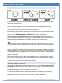
WEATHER FORECAST AND TENDENCY
W EATHER FORECASTING ICONS
For every sudden or significant change in the air pressure, the weather icons will update accordingly to
represent the change in weather.
Every time a new average pressure value has been obtained (once per minute); this value is compared
with an internal reference value. If the difference between these values is bigger than the selected
weather tendency sensitivity, the weather-icon changes, either for worse or for better. In this case, the
current pressure value becomes the new weather tendency reference.
If the icons do not change, either the air pressure has not changed or the change has been too small for
the Weather Station to register. You may adjust the "sensitivity" of the pressure change check in the
setting mode–see WEATHER TENDENCY SENSITIVITY in the manual settings above.
The displayed icon forecasts the weather in terms of getting better or worse and not necessarily
sunny or rainy as each icon indicates. For example, if the current weather is cloudy and the rainy icon is
displayed, it does not mean that the product is faulty because it is not raining. It simply means that the air
pressure has dropped and the weather is expected to get worse but not necessarily rainy.
Note: After set up, readings for weather forecasts should be disregarded for the next 48-60 hours.
This will allow sufficient time for the Weather station to collect air pressure data at a constant altitude and
therefore result in a more accurate forecast.
Common to weather forecasting, absolute accuracy cannot be guaranteed. The weather forecasting
feature is estimated to have an accuracy level of about 75% due to the varying areas the Weather Station
has been designed for use. 75% accuracy is comparable to the best meteorological forecasting rate. In
areas that experience sudden changes in weather (for example, from sunny to rain), the Weather Station
will be more accurate compared to use in areas where the weather is stable most of the time (for
example, mostly sunny).
If the Weather Station is moved to another location significantly higher or lower than its initial standing
point (for example, from the ground floor to the upper floors of a house), discard the weather forecast for
the next 48-60 hours. The Weather Station may mistake the new location as being a possible change in
air-pressure when really it is due to the slight change of altitude.
W EATHER TENDENCY INDICATOR
Working together with the weather icons is the weather tendency indicators (arrows located on the left
and right sides of the weather icons). When the indicator points upwards, it means that the air-pressure
is increasing and the weather is expected to improve, but when the indicator points downwards, the airpressure is dropping and the weather is expected to become worse.
For example, if the indicator is pointing downwards together with cloud and sun icons, then the last
noticeable change in the weather was when it was sunny (the sun icon only). Therefore, the next change
in the weather will be cloud with rain icons since the indicator is pointing downwards.
Model WS-2816U-IT
www.lacrossetechnology.com/support
P a g e | 19
Note: Once the weather tendency indicator has registered a change in air pressure, either the
upward or downward tendency arrow will be displayed until the tendency changes again.
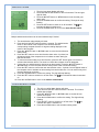
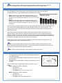
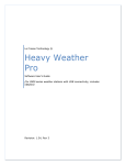
AIR PRESSURE HISTORY GRAPH
The LCD shows the relative air pressure value and the air pressure history on a bar graph.
Press the SET button to toggle between Mode1 and Mode2 of the display.
Mode 1: The bar graph displays the air pressure history of the
past 24 hours in seven steps. The horizontal axis represents the
last 24 hours of air pressure recording (-24, -18, -12, -8, -6, -3 and
0 hour).
Mode 2: The bar graph displays the air pressure history of the
past 72 hours in seven steps. The horizontal axis represents the
last 72 hours of air pressure recording (-72, -48, -36, -24, -12, -6
and 0 hour).
The vertical bars are plotted at each of the seven steps and give the trend over the recorded period. The
0 hour vertical bar will always display at the midline height to indicate the current air pressure. The
varying height of bars in other columns on the graph indicates a relative change in air pressure up or
down from the 0 hour.
New pressure measurements are compared to previously recorded pressure measurements. The
pressure change is expressed by the difference between the current ("0h") and the past readings in
divisions of ±0.06 inHg or ±2 hPa. If the bars are rising from left to right, this indicates that the weather is
getting better due to an increase in air pressure. If the bars are falling from left to right, this indicates that
the weather is expected to get worse due to a drop in air pressure.
At every full hour, the current air pressure is used as a basis for the display of a new graph bar. The
existing graph is then moved one column to the left.
Note: For accurate barometric pressure trend, the weather station should operate at the same
altitude. Should the unit be moved (for instance, from the ground to the second floor of the house), the
readings for the next 48-60 hours should be discarded.
Note: The bar graph will scroll right to left regularly to prevent LCD burnout.
WIND DIRECTION AND W IND SPEED MEASUREMENT
The longest pointer on the outer circle of the compass indicates the
current wind direction.
The last 6 wind directions may be displayed with shorter pointers on
the inner circle.
The wind direction (abbreviation or degrees) is displayed in center of
compass.
Press the SET button to toggle between Mode1 and Mode 2 of the
display.
Mode 1 displays the following wind data:
Wind direction
Wind chill in F or C
Wind speed in mph, km/h, bft, knots or m/s
Mode 2 displays the following wind data:
Wind direction
Wind chill in F or C
Wind gust in mph, km/h, bft, knots or m/s
Model WS-2816U-IT
www.lacrossetechnology.com/support
P a g e | 20
RAINFALL MEASUREMENT
The 1hour, 24-hour, week, month or total rainfall measurement is displayed in the unit of inch or mm.
For all measurements, it is important time and date are set correctly on your display.
1-HOUR RAIN: The 1-hour rain reflects rain that has fallen from current time and back 1-hour. It
updates every four minutes (15 measurements). The hour is not a fixed clock time measurement. It is
literally an ongoing “last 60 minutes” timer.
24-HOUR RAIN: The 24-hour rain reflects the rain that has fallen from current time and back 24hours. This is not a midnight to midnight measurement. The day is not a fixed clock time
measurement. It is literally an ongoing “last 24 hours” timer.
WEEKLY RAIN: The amount of rainfall of the previous week. Week: Rain total for the week is reset
every 7 days. Week begins 1 day before the day the batteries are first inserted into the weather
station. For example, if the batteries are inserted on a Thursday, the start of the weekly totals will be
Wednesday of each week.
MONTHLY RAIN: Monthly rain reflects the previous month’s rain and will update 12AM the first day
of the month.
TOTAL RAIN: Total rain will remain until you manually reset this value. Total rain reflects the rain
from time of display set-up until you manually reset the total rain.
Note: RESET RAIN: Press and release the MIN/MAX button until the display shows the Total
Rainfall value. Press the ▲/DATE button. The total rainfall amount will be reset to 0, and the
time updated to current time.
MIN/M AX WEATHER DAT A
The weather station will automatically record the maximum and minimum value of the various weather
data with time and date of recording. Press and release the MIN/MAX button to view the following stored
maximum and minimum weather data:
1. MIN/MAX indoor temperature with the date and time of recording
2. MIN/MAX indoor humidity with the date and time of recording
3. MIN/MAX outdoor temperature with the date and time of recording
4. MIN/MAX outdoor humidity with the date and time of recording
5. MAX wind gust with the date and time of recording
6. Total rainfall with the date the rainfall total was last reset.
Note: If the rainfall total has not yet been reset, "---. --. ---- will be displayed for the date.
MAX icon
RESET THE MIN/MAX W EATHER DATA
1. Press MIN/MAX button to show the desired weather data.
2. Press ▲/DATE button. The stored value will be reset to the current value and current time.
Note: Each MIN or MAX weather data value will need to be reset independently.
RESET TOTAL RAINFALL AMOUNT
The total rainfall measurement is displayed in the unit of mm or inch. It shows the total rainfall
accumulated since last reset of the total rainfall amount.
In either Mode 1 or Mode 2 display, press and release the MIN/MAX button until the display shows the
Total Rainfall value.
Press the ▲/DATE button to reset the Total Rainfall reading on the display. The total rainfall amount will
be reset to 0, and the time is updated to current time.
Model WS-2816U-IT
www.lacrossetechnology.com/support
P a g e | 21
Note: Until the first rainfall total reset is performed, the time and date of the total rainfall are displayed
as "- - -.--. ----". After the rainfall total is reset, the rainfall total display will indicate the date and time of the
last rainfall total reset.
COMMON TERMS
RELATIVE HUMIDITY
Relative humidity is how close the air is to saturation (how much moisture the air can hold). On a warm
day, more water can evaporate as there is more thermal energy to do the work of evaporation. Generally
the higher the temperature, the lower the RH as more evaporation takes place.
W IND CHILL-EQUIVALENT TEMPERATURE
A fictional temperature that is felt by human beings under certain conditions instead of the measured
temperature which can be taken into account during low temperatures. For La Crosse Technology®
products, these conditions are a Temperature below 40°F and a wind velocity above 5 mph.
W IND GUST
A wind gust is a sudden, brief increase in the speed of the wind (less than 20 seconds) followed by a lull.
This is different from a sustained wind.
MOUNTING AND PLACEMENT OF SENSORS AND WE ATHER ST ATION
IMPORTANT: Ensure that all of the sensor data can be received at the intended mounting locations
before you drill mounting holes. The outdoor sensors have a wireless range of 200 feet. Keep in mind
that the 200 foot range equates to an open-air scenario with no obstructions. Each obstruction (roof,
walls, floors, ceilings, etc.) will reduce the range.
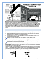
The thermo-hygro sensor measures outdoor temperature & humidity and collects the data from the
wind and the rain sensors and sends all outdoor weather data to the wireless weather station, so the
thermo-hygro sensor must be within the 200 foot wireless range of the wireless weather station. This
allows the wind and rain sensors to be placed relative to the thermo-hygro sensor rather than the
wireless weather station. See the Wireless Connection Diagram below.
The wind and rain sensors must be mounted within the 200 foot wireless range of the thermo-hygro
sensor and on the same side of the house. In addition, 915 MHz sensors transmit better at a
minimum mount height of 6 feet.
The wireless weather station must be within the 200 foot wireless range of the gateway to upload
weather data to the Internet.
Model WS-2816U-IT
www.lacrossetechnology.com/support
P a g e | 22
If the sensor wireless reception icons drop from the weather station as you move them into their
intended locations, the sensors may be too far from the wireless weather station. Try moving the weather
station or the sensors closer and wait a few minutes to see if the wireless reception icons display again.
If the wireless reception icons are still not displayed after re-positioning the sensors or the wireless
weather station, hold the ▲/DATE button for 2 seconds to re-synchronize the weather station with the
sensors.
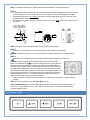
W IND SENSOR
The wind sensor must be installed with the front of the sensor (the solar panel) facing true south, or
the reported wind direction will not be accurate.
Mount within the 200 foot wireless range of the thermo-hygro sensor and on the same side of the
house. The roof may or may not be an ideal mounting location.
Secure the main unit to the shaft of the mast holder. Use the right-angle adaptor to mount the wind
sensor on a horizontal mast or surface.
Fasten the wind sensor to a suitable mast using the U-bolt, washers and nuts included.
Note: Mount the wind sensor onto a mast, at a minimum height of 6 feet, so the wind can reach the
sensor unobstructed from all directions for an accurate reading. The ideal mast is between 0.62" and
1.3” in diameter. The wind sensor DOES NOT have replaceable batteries; it consumes solar power
and charges the internal battery pack automatically.
Note: Do not open the wind sensor. This will void the warranty.
Mounting Masts: A suitable mast must be made entirely of a non-conductive material (e.g. treated wood,
electrical grade metal or electrical grade PVC).
The issue is the static electricity transmission capability of the entire pipe, which can lead to erratic wind
readings, or loss of signal. Coating or painting a pipe does not resolve the static or RF interference risks,
as the inside of the material can conduct. The color gray is also not a guarantee of electrical grade
protection. Any non-electrical grade mast may conduct, which may result in data spikes, RF interference,
etc.
Model WS-2816U-IT
www.lacrossetechnology.com/support
P a g e | 23
RAIN SENSOR
Mount the rain sensor on a level surface in an open area within the 200 foot wireless range of the
thermo-hygro sensor and on the same side of the house.
Mount the rain sensor at least 6 feet off the ground and level for optimum wireless transmission.
The rain sensor should be accessible to allow for periodic cleaning of debris or insects.
To avoid frequent build-up of debris, do not mount the rain gauge too close to the trees or plants.
Remove the funnel portion (cover) of the rain gauge by twisting it firmly counter clockwise.
Hold the base of the rain gauge flat against the mounting surface then use a level
to make sure the rain gauge (as it rests on the mounting surface) is horizontally
level.
Use a pencil to trace the inside of the mounting holes on the base of the rain
gauge to mark the screw locations.
Drill a hole in the center of each marked location.
Hold the rain gauge against the mounting surface so the holes on the base are
aligned with screw holes, and then thread washer head screws (not included) into
each hole and use a screwdriver to gently snug the screws.
Note: Do not over-tighten the mounting screws.
The Rain Gauge is self-emptying and can be left out all year or stored in the
winter. If stored for the winter, remove the batteries to avoid leakage.
Be aware of other wireless rain gauges in the area that may cause interference.
THERMO-HYGRO SENSOR
The thermo-hygro sensor is "weather resistant", but not "waterproof".
To ensure an extended life for the sensor, mount it in a semi-covered place out of the
elements at a minimum height of 6 feet.
An ideal location for the thermo-hygro sensor is under the eaves on the North side
of the house to avoid the effects of sunlight.
Mount the sensor 18" down from the eaves to ensure optimum performance. This will
assure the temperature of the air coming out of the attic will not affect data collected by the
sensor.
The cap on the sensor is for proper airflow for humidity reading and not rain protection. The
Thermohygro sensor can withstand rain, snow and temperature extremes. Standing rain
and snow may soak into the sensor and cause failure.
To wall mount the thermo-hygro sensor, fix the wall holder onto the desired wall using the included
screws, plug the sensor firmly into the wall holder and replace the rain cover if it is not already in
place.
Note: After mounting the units, if the weather data is not received, press and hold the ▲/DATE button
for 2 seconds to synchronize the weather station to the sensors.
W EATHER STATION
The Professional Weather Station is free standing with the base stand or can be wall mounted.
Wall mount:
Fix a screw (not supplied) into the desired wall, leaving the head extended out the by
about 0.2 inches (5mm).
Hang the weather station onto the screw. Ensure that it locks into place before
releasing the professional weather station.
Free standing: Simply pull out the stand to the back of the weather station and place on
a flat surface.
Model WS-2816U-IT
www.lacrossetechnology.com/support
P a g e | 24
Position:
Choose a location 6 feet or more from electronics such as cordless phones, gaming systems,
televisions, microwaves, routers, baby monitors, etc., which can prevent signal reception.
Place within range of the outdoor transmitters. The maximum transmitting range in open air is 200
feet (60 meters).
Be aware of electrical wires and plumbing within a wall. This will interfere with signal reception.
Obstacles such as walls, windows, stucco, concrete, and large metal objects can reduce the range.
Position the weather station to receive outdoor data from the thermo-hygro sensor and send data to
the gateway.
GATEW AY
Position the gateway within range (200 feet open air) of the
weather station.
The gateway should be installed indoors in an easy-to-reach
location.
Registration requires that you press the gray button on the
gateway.
It can be mounted securely to the wall with the included mounting
plate and drywall anchors.
Note: If you require a longer LAN cable to mount the gateway in a
desired location, any standard Category 5 network cable will work, but
a crossover cable may not work. Crossover cables designed to connect two computers without
networking hardware may not work with your gateway.
Note: Network cables usually have length limitations. The same length limitations will apply that apply
to computers on your home network.
STAND- ALONE WEATHER ST ATIO N OR INTERNET CONNECTED WEATHER ST ATION WITH
REMOTE MONITORING & ALERTS
Use the weather station as:
1. (OPTION 1) Stand-alone weather station with wireless backyard weather sensors. Included
Gateway Set and Activation Card is not required.
Wireless weather station information and manual are available at: www.lacrossetechnology.com
2. (OPTION 2) Internet-connected weather station with remote monitoring and alerts uses the
included Gateway Set and Activation Card to enable the included Remote Monitoring & Text/E-mail
Alerts from www.lacrossealerts.com
Remote Monitoring & Text/E-mail Alerts are included to remotely monitor your home & backyard
weather on www.lacrossealerts.com using your smartphone, tablet or computer.*
Set & receive custom e-mail & text alerts for:*
o Outdoor temperature & humidity
o Wind & rain+
o Barometric pressure
o Indoor temperature & humidity
High-speed Internet access, network router & Internet-enabled device with web browser required
(not included)
E-mail account and/or SMS text ability for remote monitoring & alerts required (not included)
Connect the gateway to your router (not included) with the LAN cable, for wireless connection to
the weather station.
Note: See the included Activation Card for the activation key to enable remote monitoring and
alerts.* There is no app or software to install.
All remote monitoring is done on www.lacrossealerts.com with an account that you create if you wish to
use these added features.*
Model WS-2816U-IT
www.lacrossetechnology.com/support
P a g e | 25
SPECIFICATIONS
INDOOR TEMPERATURE
41°F to 104°F (5°C to 40°C) (“OF.L” displayed if outside this range)
INDOOR HUMIDITY
3% to 99% (“- -” displayed if < 1%, "99" displayed if 99%)
OUTDOOR TEMPERAT URE
-40°F to 139.8°F (-40°C to 59.9°C) (“OF.L” displayed if outside this range)
OUTDOOR HUMIDITY
3% to 99% (“- -” displayed if < 1%, "99" displayed if 99%)
W IND SPEED/ GUST
0 to 111.8 mph with resolution of 0.22 mph
0 to 180 km/h with resolution of 0.36 km/h
0 to 12 bft
0 to 97.1 knots with resolution of 0.19 knots
0 to 50 m/s with resolution of 0.1 m/s
(Displays "OF.L" when > 111.62 mph; 49.9 m/s)
W IND CHILL
Down to -40°F (displays "OF.L" if outside this)
RAINFALL
0" to 393.7" (0 to 9999 mm) (displays "OF.L" when > 393.7")
OUTDOOR DATA RECEPTION INTERVAL
Temperature and humidity data every 13 seconds sent to the display
Wind data every 17 seconds sent to the TH sensor
Rain data every 19 seconds sent to the TH sensor
AIR PRESSURE
Relative pressure pre-set range: 27.17 to 31.90 inHg (919 to 1080 hPa)
Measured every 15 seconds
TRANSMISSION RANGE
Rain to Thermo-hygro:
Wind to Thermo-hygro:
Thermo-hygro to Weather Station:
Weather Station to Gateway:
200 feet in open space
200 feet in open space
200 feet in open space
200 feet in open space
POW ER CONSUMPTION
W EATHER CENTER
3 x C size batteries (IEC LR14, 1.5V)
Approximately 24 months (Alkaline batteries recommended)
Model WS-2816U-IT
www.lacrossetechnology.com/support
P a g e | 26
THERMO-HYGRO TRANSMITTER
2 x C size batteries (IEC LR14, 1.5V)
Approximately 24 months (Alkaline batteries recommended)
RAIN SENSOR
2 x AA size batteries (IEC LR6, 1.5V)
Approximately 24 months (Alkaline batteries recommended)
W IND SENSOR
100% solar-powered (built-in power cell, no batteries necessary)
High-efficiency solar panels maintain operation in every season
GATEW AY
20-volt A/C power cord
DIMENSIONS
W EATHER CENTER
8.665” L x 1.594” W x 6.795” H (220.1 x 40.5 x 172.6 mm)
THERMO-HYGRO TRANSMITTER
3.13" L x 3.54" W x 7.45" H (79.4 x 89.8 x 189.3 mm)
RAIN SENSOR
5.2" DIA. x 7.2" H (131.6 DIA. x 182.7 mm)
W IND SENSOR
9.84" L x 5.74" W x 7.57" H (250 x 145.9 x 192.3 mm) without mounting base
GATEW AY
1.574” L x 0.787” W x 4.055” H (40 x 20 x 103 mm)
CARE AND M AINTENANCE
Do not mix old and new batteries
Do not mix Alkaline, Standard, Lithium or Rechargeable Batteries
Always purchase the correct size and grade of battery most suitable for intended use.
Replace all batteries of a set at the same time.
Clean the battery contacts and also those of the device prior to battery installation.
Ensure the batteries are installed with correct polarity (+and -).
Remove batteries from equipment which is not to be used for an extended period of time.
Remove expired batteries promptly.
When cleaning the display and casings, use a soft damp cloth only. Do not use solvents or scouring
agents as they may mark the LCD and casings.
Do not submerge the unit in water.
Special care shall be taken when handling a damaged LCD display. The liquid crystals can be
harmful to user's health.
Do not make any repair attempts to the unit. Return them to their original point of purchase for repair
by a qualified engineer. Opening and tampering with the unit may invalidate their guarantee.
Never touch the exposed electronic circuit of the device. There is a danger of electric shock should it
become exposed.
Do not expose the display to extreme and sudden temperature changes, this may lead to rapid
changes in forecasts and readings and thereby reduce their accuracy.
Model WS-2816U-IT
www.lacrossetechnology.com/support
P a g e | 27
ALERTS AND MONITORING DISCLAIMER
* Disclaimers: La Crosse Technology, LTD. (“La Crosse”) provides various alert and monitoring services
to aid users. (1) Service providers may charge users for alert services. Standard messaging and data
rates apply and will be billed to the customer’s wireless account. Customers may be unable to receive
text messaging or data service in some areas due to unavailability of service. (2) La Crosse shall not be
liable for accuracy, usefulness or availability of data transmitted via the service. Users are solely
responsible for damages to persons or property by service use.
LIABILITY DISCLAIMER
The electrical and electronic wastes contain hazardous substances. Disposal of electronic waste in
wild country and/or in unauthorized grounds strongly damages the environment.
Please contact the local or/and regional authorities to retrieve the addresses of legal dumping
grounds with selective collection.
All electronic instruments must from now on be recycled. User shall take an active part in the reuse,
recycling and recovery of the electrical and electronic waste.
The unrestricted disposal of electronic waste may do harm on public health and the quality of
environment.
As stated on the gift box and labeled on the product, reading the “User manual” is highly
recommended for the benefit of the user. This product should not be thrown in general rubbish
collection points.
The manufacturer and supplier cannot accept any responsibility for any incorrect readings and any
consequences that occur should an inaccurate reading take place.
This product is designed for use in the home only as indication of the temperature.
This product is not to be used for medical purposes or for public information.
The specifications of this product may change without prior notice.
This product is not a toy. Keep out of the reach of children.
No part of this manual may be reproduced without written authorization of the manufacturer.
WARRANTY INFORM ATION
La Crosse Technology, Ltd. provides a 1-year limited time warranty (from date of purchase) on this
product relating to manufacturing defects in materials & workmanship.
View full warranty details online at:
www.lacrossetechnology.com/warranty_info.pdf
For warranty work, technical support or other information contact:
La Crosse Technology, Ltd
2830 South 26th St.
La Crosse, WI 54601
Contact Support:
608-782-1610
Online Product Support:
www.lacrossetechnology.com/support
Product Registration:
www.lacrossetechnology.com/support/register
Protected under U.S. Patents:
5,978,738 | 6,076,044 | RE43903 | 6,761,065
Model WS-2816U-IT
www.lacrossetechnology.com/support
P a g e | 28
FCC ST ATEMENT
This equipment has been tested and found to comply with the limits for a Class B digital device, pursuant
to part 15 of the FCC Rules. These limits are designed to provide reasonable protection against harmful
interference in a residential installation. This equipment generates, uses and can radiate radio frequency
energy and, if not installed and used in accordance with the instructions, may cause harmful interference
to radio communications. However, there is no guarantee that interference will not occur in a particular
installation. If this equipment does cause harmful interference to radio or television reception, which can
be determined by turning the equipment off and on, the user is encouraged to try to correct the
interference by one or more of the following measures:
Reorient or relocate the receiving antenna.
Increase the separation between the equipment and receiver.
Connect the equipment into an outlet on a circuit different from that to which the receiver is
connected.
Consult the dealer or an experienced radio/TV technician for help.
This device must not be co-located or operating in conjunction with any other antenna or transmitter.
Operation is subject to the following two conditions:
(1) this device may not cause harmful interference, and
(2) this device must accept any interference received, including interference that may cause undesired
operation.
Caution!
The manufacturer is not responsible for any radio or TV interference caused by unauthorized
modifications to this equipment. Such modifications could void the user authority to operate the
equipment.
All rights reserved. This manual may not be reproduced in any form, even in part, or duplicated or
processed using electronic, mechanical or chemical process without the written permission of the
publisher.
This booklet may contain errors or misprints. The information it contains is regularly checked and
corrections are included in subsequent editions. We disclaim any responsibility for any technical error or
printing error, or their consequences.
All trademarks and patents are recognized.
Model WS-2816U-IT
www.lacrossetechnology.com/support
P a g e | 29