1
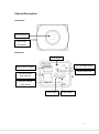
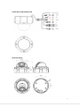
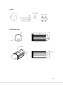
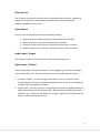
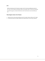
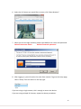
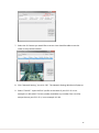
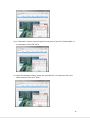
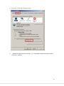
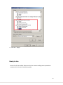
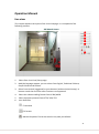
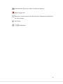
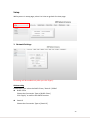
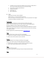
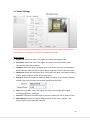
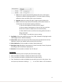
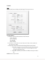
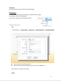
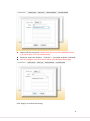
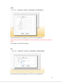
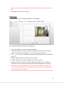
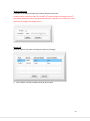
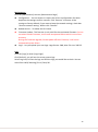
2M / HD 720P Internet Protocol Camera User Manual Ver.2012 / 08 1 Table of Contents Reading Before Using Warning Before Using Package Content Physical Description Network & Basic Connecting Minimum PC Requirements Accessing IP Camrea ActiveX Setup Ready to Use Operation Manual Live view page introduction Setup 1. Network ---IP Networking ---Dynamic DNS ---UPnP ---Bonjour ---Connection Ports ---IP Filter ---E-mail Server 4 4 5 6 11 11 12 18 20 21 23 24 24 24 25 25 25 2. Camera ---Image Setting ---Text Overlay 3. Media ---Video 26 26 27 28 28 ---Audio 29 4. Events ---Event Servers ---Motion Setup ---Tampering Detection ---Alarm I/O ---Alarm Definition ---Schedule Definition Example Operation 5. System ---Information ---System Name ---Date and Time ---Users Example Operation ---Maintenance ---Logs 30 30 33 34 34 35 37 48 38 38 38 38 38 66 39 69 39 2 Copyrights & Trademarks Copyright © 2012 Trademarks Microsoft and Windows are registered trademarks of Microsoft Corporation. All other trademarks mentioned in this document are trademarks of their respective owners. Disclaimer This document is intended for general information purposes only, and due care has been taken in its preparation. Any risk arising from the use of this information rests with the recipient, and nothing herein should be construed as constituting any kind of warranty. The distributor reserves the right to make adjustments without prior notification. All names of people and organizations used in these documents examples are fictitious. Any resemblance to any actual organization or person, living or dead, is purely coincidental and unintended. 3 Reading Before Using You should read all the safety and operating instructions before using this product. The use of surveillance devices may be prohibited by law in your country. The IP Camera is not only a high-performance web-ready camera, but can also be part of a flexible surveillance system. It is the user’s responsibility to ensure that the operation of such devices is legal before installing this unit for its intended use. Warning Before Using 1. Abnormal: Power off the IP Camera immediately when the smoke or unusual odors are detected. 2. Voltage: Don not use the power supply with other voltages, if you use a power supply with different voltage than the one included with this device. It is likely to be damaged or damage other equipments / personnel. 3. Humidity: Keep the IP Camera dry inside. If it becomes wet, power off is necessary! Do not place it in high humidity environments. 4. Temperature: Refer to your user’s manual for the operating temperature; do not place around heat sources, direct sunlight. 5. Disassemble: Do not open the housing of this IP Camera; avoid disassembling and inserting the sharp or tiny things. 6. Accessory: Do not use attachment / accessory not recommend by Raylios. All warranty will be voided in the situations above. 4 Package Content Box Cam *Lens not included Vandal Dome IR Vandal Dome (35*IR LED) IR Vandal Dome (50*IR LED) *accessory package is included IR Tube IR Tube (Slim type) *accessory package is included Power Adaptor Software CD Product CD in the package contains the following: 1. Search Tool (Skate2). 2. CMS. 3. User Manual / QIG 5 Physical Description Front Panel Lens & Sensor Back Focus Adjustment Back Panel Reset Button DC 12V Power Input Digital Input / Output Power Status LED Ethernet 10/100 RJ45 Connect Auto-Iris Control Cable Socket Audio Input Audio output 6 Vandal Dome (IR/ Without IR) IR Vandal Dome 7 IR Tube IR Tube (Slim type) 8 Ethernet Port The IP device connects to the Ethernet via a standard RJ45 connector. Supporting NWAY, this IP device can auto detect the speed of local network segment (10Base-T/100Base-TX Ethernet). Reset Button You can use the Reset Button to do the following settings: 1. 2. 3. 4. Restore to factory default: Press the reset button for 8 seconds. Reset the IP Cam: Press the reset button for 1 second. Enable the Easy Focus function: Quick press twice within a second. Disable the Easy Focus function: Quick press twice within a second. Audio Input / Output The IP device supports audio input and output with earphone jack. Digital Input / Output Used in applications like motion detection, event triggering, time lapse recording, alarm notifications, etc., the I/O terminal connector provides the interface to: 1. Transistor output – for connecting external devices such as relays and LEDs. Connected devices can be activated by Output buttons on the Live View page or through video management software. 2. Digital Input – An alarm input for connecting devices that can toggle between an open and closed circuit, for example: PIRs, door/window contacts, glass break detectors, etc. The device will detect the change in digital input and transmit the signal to video surveillance servers. 9 LED While connecting the IP Camera to power, the IP Camera immediately starts the self- test, at this moment the power LED turns orange. After the self-test, the power LED will turn green, means the Ethernet or WiFi connections are successfully set up. Mounting the Lens to the Camera 1. Mount the lens by turning clockwise onto the camera mount slowly until it stops. 2. Connect the Auto-Iris control cable to the socket (Auto-Iris lens only, optional) 10 Network & Basic Connecting With PoE (Power Over Ethernet) supported switch or injector: 1. Connect IP Camera to the switch / injector by CAT 5 / CAT 6 network cable with RJ45 connector. 2. Connect your switch / injector to PC with another CAT5 / CAT6 network cable. Without PoE (Power over Ethernet) supported switch or injector: 1. Connect the power adaptor to IP Box Camera. 2. Connect IP Camera to the switch / injector by CAT 5 / CAT 6 network cable with RJ45 connector. 3. Connect a PC to the switch / injector by CAT 5 / CAT 6 network cable with RJ45 connector. Minimum PC Requirements CPU:Intel Core i3-2120 Dual Core 3.3GHz or up Memory:2G(Suggest to have 4G or more, for better system performance) OS:Windows Vista,/2000/XP/ Win 7 Browser:Internet Explorer 7.0 or later version (Also Supports FireFox. Chrome) 11 Accessing Camera You can easily find and access the IP Camera with our “IP Camera Search Tool”, which is in our package CD with the camera. 1. Put the CD into the CD/DVD player in your PC. The AutoRun will start automatically. 2. Click “IP Camera Search Tool” 3. If your PC can’t execute AutoRun, please execute the program “autorun.exe” in the CD. 4. Click “Search”, the IP Cameras will be found with ID, Name, IP address…etc. 5. Select the IP Camera you would like to access. You should be able to see the video in the preview window. 12 6. Select the IP Camera you would like to access, click “Open Browser”. 7. When you see the login window, please input default user name and password: Default Username: admin Default Password: password 8. After logging in, you will see the live view from camera. To go to the setup page, select “Setup” from the menu on the top right. If you are using a single camera, this is enough to access the device. If you are using multiple IP Cameras, repeat the above procedures. 13 If you can not access the camera after above mentioned procedure, you may have your PC with fixed IP, in this case please follow the steps to change the IP of IP Camera to the same subnet with your PC: 1. Check you PC’s IP address by going to Control Panel Manage Network Connections Right click on the connection to change Option TCP/IP IPv4 Properties. 2. You can find your PC’s IP address in the “IP Address” column. In our example it’s 192.168.1.99 Please memorize it. Select “OK” 3. Put the CD into the CD/DVD player in your PC. The AutoRun will start automatically. 4. Click “IP Camera Search Tool“ 5. If your PC can’t execute AutoRun, please execute the program “autorun.exe” in the CD. 6. Click “Search”, the IP Cameras will be found with ID, Name, IP address…etc. 14 7. Select the IP Camera you would like to access. You should be able to see the video in the preview window. 8. Click “Network Setting”, the click “OK”. The Network Setting Window will pop-up. 9. Select “Fixed IP”. Input the first 3 prefix as the same of your PC’s IP. In our example it’s 192.168.0. The last number should be any number from 1 to 254, except the one your PC’s IP is, in our example it’s 101. 15 10. In “Netmask” column, input the prefix as the same of your PC’s Subnet Mask. In our example it’s 255.255.255.0 11. Input the Gateway number, please ask your MIS for it or check your PC in the same network. Then click “Save”. 16 12. Click “Search” again, you will find your camera with a new IP address which you assigned. 13. Select the IP Camera you would like to access. You should be able to see the video in the preview window. 14. Select the IP Cam you would like to access, click “Open Browser”. 15. When you see the login window, please input default user and password: Default Username: admin Default Password: password 17 16. After logging in, you will see the live view from camera. To go to the setup page, select “Setup” from the menu on the top right. Set ActivX 1. Toolbar→Tools→Internet Options 18 2. Security→Click the Custom Level… 3. “Download signed ActiveX controls” and” Download unsigned ActiveX controls”, Click the “ Prompt” 19 4. Click the “ Alppy” Ready to Use Access the IP Cam and be able to see the live view according to the procedures mentioned in this quick installation guide。 20 Operation Manual Live view This chapter explains the layout of the Live View page. It is composed of the following sections: ① ② ③ ④ ⑤ ⑥ 1. 2. 3. Select from Live View/ Setup page. Multiple language support, you can select from English, Traditional Chinese, Simple Chinese and Russian. Select from ActiveX (suggested) or pure browser (without ActiveX setup). In 4. 5. 6. browser mode there will be some functions not supported. Select the video encoding format from H.264/ MJPG. Select transport protocol from HTTP/ UDP/ TCP Icon Definition Fit window Full screen Manual Snapshot: file can be saved in the path you defined 21 Manual Record: file can be saved in the path you defined Manual Trigger D/O Easy Focus: click this button and check the focus adjustment bar below the live view window. MIC/ Mute Audio/ Mute 22 Setup While you are in setup page, select Live View to go back live view page. 1. Network Settings All settings will be enabled only after you click “Apply”. IP Networking Connection Type: select the DHCP Client / Static IP / PPPoE DHCP Client Choose the Connection Type as [DHCP Client] Click “Apply” to confirm the DHCP function. Static IP Choose the Connection Type as [Static IP] 23 1. 2. 3. 4. 5. IP Address: you can setup the IP address of this IP camera, kindly refer to the Connect to device and setup IP for more detail setting. Subnet Mask: should be 255.255.255.0 Gateway:192.168.1.1 DNS1:168.95.1.1 DN2: 168.95.192.1 PPPoE Choose the Connection Type as [PPPoE] PPPoE requires an account provided by your ISP Edit the User Name and Password, and then confirm the password. Click “Apply” to confirm the Edition and PPPoE function. Dynamic DNS Click the [Dynamic DNS] item to show the [Dynamic DNS setting page] DDNS is a service that allows your IP Camera, especially when assigned with a Dynamic IP address, to have a fixed host and domain name. DDNS Service: click the check point to enable or disable the DDNS Service function. Refer to the following links to apply for a dynamic domain account when selecting other DDNS providers: Dyndns.org (Dynamic) / Dyndns.org (Custom): www.dyndns.com UPnP Click the [UPnP] item to display the [UPnP setting page] 1. Enable UPnP: Checkbox to enable or disable the UPnP function. 2. Device name: Edit the device name in text field. Bonjour Click the [Bonjour] item to display the [Bonjour setting page] Bonjour let IP Camera work with MAC (Apple) Operation System. 1. Enable Bonjour: Checkbox to enable or disable the Bonjour function. 2. Service name: Edit the device name in the text field. HTTP The default HTTP port is 80. Check box to enable JPEG streaming’s Account/ Password authentication. RTSP 24 The default RTSP port is 554. The default RTSP client number is 6, you can change it according to how many clients are allowed to connect this IP Cam via RTSP. Check box to enable RTSP stream’s Account/ Password authentication. Check box to enable RTSP over HTTP. RTP The default RTP (over UDP) Port is 6000 (starting port), the IP Cam will use starting port + 100 ports for the RTP connections. Please contact your MIS to confirm which RTP ports are valid for IP Cam use. IP Filter Check box to enable IP Filter. You can build up Accept IP Address or Reject IP Address groups by selecting from the “Rule”. Then input the IP Address you accept or reject in the columns blow, then click “+”. After finishing all inputs, click “Apply”. Email Server:let you setup the SMTP server, you can choose from Gmail, Hotmail, Yahoo or to self-define other SMTP server. 25 2. Camera Settings You can refer to the preview window to fine-tune the image. When complete with the settings on this page, click “Apply” to enable the settings. Image Setting 1. Brightness: Select the value. The higher this value, the brighter view. 2. Saturation: Select the value. The higher this value, the more colorful view. Too colorful might be unnatural. 3. Contrast: Select the value. The higher this value, there are more level between Black & White, make the detail clearer. Noise might be clearer at the same time 4. Sharpness: Select the Sharpness value. The higher this value, the shape of item is clearer. Noise might be clearer at the same time. 5. Exposure: Select the Exposure mode for 60Htz or 50Htz. If you choose “Manual Shutter, then you can select the shutter speed from the menu. 6. AGC: Select the AGC value. The higher this value, the stronger each signal, including brightness, and noise. 7. Auto Iris: Check box to enable Auto Iris function while you use an Auto Iris Lens. 8. White Balance: Select the White Balance mode. If you select “Manual”, the R-gain/B-gain can be adjusted manually. 26 a. Auto: the IP Camera automatically adjusts the color of the light in response to different lighting condition. The white balance setting defaults to Auto and works well in most situations. b. Manual: Adjust the value of R-gain / B-gain to get the best color. c. Hold : follow the steps below to manually set the white balance to compensate for the ambient lighting conditions: 1: Set the white balance to auto and click “Apply” 2: Place a sheet of white paper in front of the lens, and then allow the IP Camera to adjust the color automatically. 3: Select Hold Current to confirm the setting while the color is being measured. 4: Click “Apply” to enable the current setting 9. Day/Night: Select the mode from Auto / On / Off / Schedule of day/night mode switch (night mode = Black and White) 10. IR Cut Filter: Select from Auto/ On/ Off to control the mechanical IR Cut Filter (Optional, only for the models with mechanical IR Cut Filter) 11. Noise Reduction: Click to enable or disable “Noise Reduction”. 12. Backlight Comp. (Backlight Compensation): Select from Off/ Center/ Peripheral according to the environment requirement. 13. Rotation: Click to enable or disable “Flip” & “Mirror” Text Overlay Click the [Text Overlay] item to display the [Text Overlay Page]. 1. Date: Checkbox to enable or disable the date of text overlay. 2. Time: Checkbox to enable or disable the time of text overlay. 3. Text: Checkbox to enable or disable the text which you edit in the column. You can input any character including = - / , : a~z A~Z 0~9. Max. to 127 characters. 27 3. Media Video Click the [Video] item to display the [Video Page]. The functions here are H.264 / MPEG-4: a. Resolution: Select the video resolution of the IP Camera UXGA: 1600x1200 HD 720: 1280x720 VGA: 640x480 QVGA: 320x240 b. Frame Rate: In UXGA mode, the max. frame rate is 15fps. In other modes, the max. frame rate is 30fps. c. Bit Rate Type: select from VBR (Variable Bit Rate)/CBR (Constant Bit Rate) i. While VBR is selected, you can also define the quality from moving the cursor in the VBR bar. (value from 1 to 100, the higher this value, the higher image quality level) ii. While CBR is selected, you can define the CBR by selecting from 28K to 6M. JPEG: Same concept as H.264 28 Audio Click the [Audio] item to display the [Audio Page]. 1. Enable Audio: Checkbox to enable or disable the Audio function. 2. Encoder type: Select the encoder type by G.726 / G.711 µ-law 3. Bit rate: Set up the bit rate by 16 / 32 Kbps of Audio Stream. 29 4. Events Click the [Events] item to display the [Events Page]. Event Servers Click the [Event Servers] item to display the [Event Servers Page]. Click [Add] to Open the setup page. Server Type: select the FTP/E-Mail/HTTP/TCP Example Operation FTP Name: Edit the name of the server Input data required according to your FTP server configuration. Click “Apply” to confirm the setting. E-Mail 30 Name: Edit the user name. Please note, the name of the different servers (FTP, Email, Http, TCP) can’t be the same. Recipient: Enter the recipient,Click the “ + “(multiple recipient is allowed) You can configure your email server setup in the Network setup page. Click “Apply” to confirm the setting. 31 HTTP Input data required according to your HTTP server configuration. Please note, the name of the different servers (FTP, Email, Http, TCP) can’t be the same. Click “Apply” to confirm the setting. TCP Input data required according to your HTTP server configuration. 32 Please note, the name of the different servers (FTP, Email, Http, TCP) can’t be the same. Click “Apply” to confirm the setting. Motion Setup Click the [Motion] item to display the [Motion Setup Page]. Up to 3 Motion Detection regions can be defined. 1. Click to add a new motion detection window. Once it is added, there will be a motion window shows in the live view screen. You can adjust column and Square, to set up the region as you want. 2. Click , then click an existed motion detection window which you would like to cancel. 3. Window Name: Setup the name of motion window. 4. Enable: Checkbox to enable or disable each motion window. 5. Sensitivity: Set the sensitivity of motion detection region (from 1 to 100), the higher this value, the easier camera considers video change to be an activity. 6. Threshold: Set the threshold of motion detection region (from 1 to 100), the event will be triggered only if the motion value (shown in the status bar)exceed the threshold value you defined. 7. Status: While there is a motion, you can find the motion value in the “status” bar. 33 Tamper Detection Checkbox to enable or disable the tamper detection function. Variation value can be set from 1% to 100%, 1% means while the image varies 1%, the tamper detection will be activated and alarmed. Therefore, the lower this value, the easier to trigger the tamper event. Alarm I/O Click the [Alarm I/O] item to display the [Alarm I/O Page] 1. Click “Name” column to edit the name of this port. 34 2. Click “Normal state” column to select from Open/Close to define the normal status of this port. 3. Current State column shows the current status of this port 4. Click “Apply” to finish the setup. Alarm Definition Click the [Definition] item to define in which condition to trigger the alarm 35 1. Name: You can define the event name 2. Alarm: a. Define Trigger Interval b. Working Time: select the Disable/Always/Manual(scheduled) c. Trigger by: Motion Detection: while motion detection is selected to trigger the alarm, you have to select motion window if you defined more than 1 motion detection window. In this example we select “motion 1” window. Input Port: while input port is selected to trigger the alarm, you have to select input source and define in which condition to trigger alarm. (Active: normal status ≠current status. Inactive: normal status = current status) System Starting: While selecting system starting, the alarm will be triggered once this IP Camera starts or re-starts. Tamper Detection: While selecting tamper detection, the alarm will be triggered by tamper detection. 3. Action: Checkbox to enable or disable the action after alarm triggered Activate output port Send E-Mail notification Send HTTP notification Send TCP notification Upload images via FTP Upload images via E-Mail 36 Schedule The schedule operations can be defined here. You can manually schedule the following actions (separate from Event actions) Activate output port Send E-Mail notification Send HTTP notification Send TCP notification Upload images via FTP Upload images via E-Mail 37 5. System This section explains how to configure the basic settings for the IP Cameras, such as the host name and system time. Click the [System] item to display the [System Page]. Information The MAC address, Model name and Firmware version of this IP Camera are shown here. System Name The IP Camera Title name/Host name/ Domain name can be defined here, to name the IP Cameras will help you identify each camera easier. All columns can be left empty if you don’t want to name them. Title Name is the one shown on the top of the live view page. Host name is the one help you identify this IP Cam easier, for example, name it “ front door” or “ warehouse”…etc. This host name will be shown in the bundled IP Cam search tool. Domain name is the one to let you define which internet domain this IP Cam belongs to. Date & Time Click the [Data & Time] item to see [Date & Time Setting Page]. The default method is Sync with time server. Method: select the [Sync with time server], you can choose the time server you would like to sync with. Method: select the [Manual] to manually input date and time Method: select the [Sync with PC] Users You can set up different roles of Viewers, Operators & Administrators. And define the user name and password for them. Administrator account allows the user to watch the live view and setup everything; but viewers account allows user only to watch the live image. Viewers: Browse only Operators: Some functions can be modified Administrators: Administrators (Maximum authority) 38 Maintenance Click the [Maintenance] to enter [Maintenance Page]. Configuration:You can export or import the IP Cam configurations for easier duplicate the settings to other cameras. Click “Restore” to restore all the settings to factory default. If you want to keep the network settings, check box “Reserve network setting” before click “Restore”. Reboot device:To reboot the IP Camera Firmware Update:This function is only valid for the nominated firmware. Do not use other brand’s firmware, it will cause unexpected failure which is out of the warranty. During the firmware upgrade, Do Not power off the IP Camera, it will cause unexpected system failure. Logo:Let you upload your own logo. Logo format: PNG; Max. file size: 200*25. Logs Click the [Logs] to enter [Logs Page]. Click [Refresh], you will see the recent system logs. Select Log level, to filter the logs and find the logs you would like to check. You can select from INFO/ Warning/ Error/ Fatal/ All. 39