Transcript
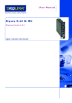
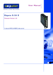
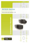
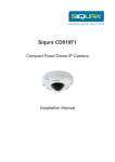
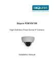
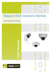
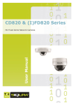
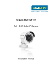
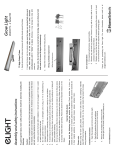
Siqura HSD626EXP Explosion-protected PTZ dome camera Supplementary installation information About this document This document is a guide for the mechanical installation of the HSD626EXP camera. For more information, see the HSD626EXP – Installation Manual. The three spacers, placed between the camera and the mounting plate, ensure an optimal field of view. Image distortion, if any, may be reduced by removing these spacers. Note, however, that adjusting the height of the camera in this way may impair the field of view when the lens is pointed horizontally. Important: The supplied manuals listed below are the governing documents. They must be followed to the letter by the installer. 53-XCC-5_B User Manual TNXCC195 DNV CE Declaration TNXCC195 DNV-2004-OSL-ATEX-0115-1 Product description Spacers Siqura HSD626EXP cameras are designed to endure in potentially explosive atmospheres and harsh environmental conditions. The camera housing is manufactured completely from Stainless Steel 316 which is ideally suited for use within offshore and onshore environments. Stainless Steel screws and mounting bracket for additional wall, ceiling, or pole mount are incorporated ensuring a totally corrosionfree unit. 5. Installation 1. 2. 3. 4. Spacers removed Make sure that the affixing surface is suitable for the weight of the PTZ unit. Mount the bracket (wall/pole/ceiling) to the wall, pole, or ceiling as required. Securely mount the PTZ unit to the wall, pole, or ceiling bracket with the bolts provided with the bracket. Loosen the Lock screw. To remove the spacers (if needed), unscrew the three screws under the mounting plate and take out the spacers. Refasten the camera on the mounting plate with the supplied shorter screws. 6. Install the (installer supplied) ATEX certified cable glands to the housing top plate. 7. Allowing sufficient slack in wires, run field wiring through gland and gland opening in the top plate. 8. Follow all procedures and regulations as laid down in the ATEX standards and IECEx rules for proper installation and sealing. 9. Connect all necessary wiring as described in the Installation Manual. 10. Screw the PTZ housing body back on to the top plate. 11. Make sure that the threads are clean and use copper grease as a lubricant. Tighten with the strap tool. 12. To complete the installation, reinstall the Lock screw (shown in step 4). Example Lock screw 13. Using a strap tool, carefully remove the PTZ housing body from the end plate. Note This is a gasketed interface which requires good torque to overcome the initial seal. Warnings The unit is heavy, so be prepared to place the unit on a secure surface after removal. The threads are greased. Take caution that dirt does not get on to the threads. © Siqura B.V. 2014 Version 1.0 (140710-1) HSD626EXP SupIM (MW10) Finished installation example