1
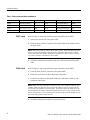
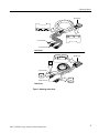
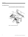
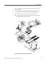
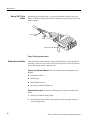
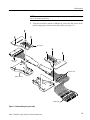
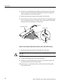
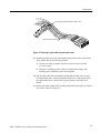
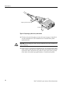
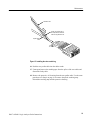
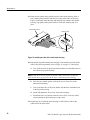
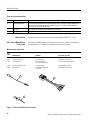
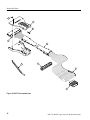
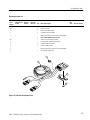
Instructions
P6417 & P6418
Logic Analyzer Probes
071-0567-00
Copyright © Tektronix, Inc. All rights reserved.
Tektronix products are covered by U.S. and foreign patents, issued and pending. Information in this publication supercedes
that in all previously published material. Specifications and price change privileges reserved.
Printed in the U.S.A.
Tektronix, Inc., P.O. Box 1000, Wilsonville, OR 97070–1000
TEKTRONIX and TEK are registered trademarks of Tektronix, Inc.
WARRANTY
Tektronix warrants that the products that it manufactures and sells will be free from defects in materials and
workmanship for a period of one (1) year from the date of shipment. If a product proves defective during this
warranty period, Tektronix, at its option, either will repair the defective product without charge for parts and labor,
or will provide a replacement in exchange for the defective product.
In order to obtain service under this warranty, Customer must notify Tektronix of the defect before the expiration
of the warranty period and make suitable arrangements for the performance of service. Customer shall be
responsible for packaging and shipping the defective product to the service center designated by Tektronix, with
shipping charges prepaid. Tektronix shall pay for the return of the product to Customer if the shipment is to a
location within the country in which the Tektronix service center is located. Customer shall be responsible for
paying all shipping charges, duties, taxes, and any other charges for products returned to any other locations.
This warranty shall not apply to any defect, failure or damage caused by improper use or improper or inadequate
maintenance and care. Tektronix shall not be obligated to furnish service under this warranty a) to repair damage
resulting from attempts by personnel other than Tektronix representatives to install, repair or service the product;
b) to repair damage resulting from improper use or connection to incompatible equipment; c) to repair any
damage or malfunction caused by the use of non-Tektronix supplies; or d) to service a product that has been
modified or integrated with other products when the effect of such modification or integration increases the time
or difficulty of servicing the product.
THIS WARRANTY IS GIVEN BY TEKTRONIX IN LIEU OF ANY OTHER WARRANTIES, EXPRESS
OR IMPLIED. TEKTRONIX AND ITS VENDORS DISCLAIM ANY IMPLIED WARRANTIES OF
MERCHANTABILITY OR FITNESS FOR A PARTICULAR PURPOSE. TEKTRONIX’
RESPONSIBILITY TO REPAIR OR REPLACE DEFECTIVE PRODUCTS IS THE SOLE AND
EXCLUSIVE REMEDY PROVIDED TO THE CUSTOMER FOR BREACH OF THIS WARRANTY.
TEKTRONIX AND ITS VENDORS WILL NOT BE LIABLE FOR ANY INDIRECT, SPECIAL,
INCIDENTAL, OR CONSEQUENTIAL DAMAGES IRRESPECTIVE OF WHETHER TEKTRONIX OR
THE VENDOR HAS ADVANCE NOTICE OF THE POSSIBILITY OF SUCH DAMAGES.
Table of Contents
General Safety Summary . . . . . . . . . . . . . . . . . . . . . . . . . . . . . . . . . . . .
Preface . . . . . . . . . . . . . . . . . . . . . . . . . . . . . . . . . . . . . . . . . . . . . . . . . . .
iii
v
Related Documentation . . . . . . . . . . . . . . . . . . . . . . . . . . . . . . . . . . . . . . . . . . . .
Contacting Tektronix . . . . . . . . . . . . . . . . . . . . . . . . . . . . . . . . . . . . . . . . . . . . . .
v
vi
Operating Basics . . . . . . . . . . . . . . . . . . . . . . . . . . . . . . . . . . . . . . . . . . .
1
Product Description . . . . . . . . . . . . . . . . . . . . . . . . . . . . . . . . . . . . . . . . . . . . . . .
Attaching Probe Labels . . . . . . . . . . . . . . . . . . . . . . . . . . . . . . . . . . . . . . . . . . . .
Connecting the Probes . . . . . . . . . . . . . . . . . . . . . . . . . . . . . . . . . . . . . . . . . . . . .
1
1
4
Reference . . . . . . . . . . . . . . . . . . . . . . . . . . . . . . . . . . . . . . . . . . . . . . . . .
7
Probe Connectors . . . . . . . . . . . . . . . . . . . . . . . . . . . . . . . . . . . . . . . . . . . . . . . . .
Loading and Equivalent Circuits . . . . . . . . . . . . . . . . . . . . . . . . . . . . . . . . . . . . .
Specifications . . . . . . . . . . . . . . . . . . . . . . . . . . . . . . . . . . . . . . . . . . . . . . . . . . . .
7
8
9
Maintenance . . . . . . . . . . . . . . . . . . . . . . . . . . . . . . . . . . . . . . . . . . . . . . .
11
Functional Check . . . . . . . . . . . . . . . . . . . . . . . . . . . . . . . . . . . . . . . . . . . . . . . . .
Inspection and Cleaning . . . . . . . . . . . . . . . . . . . . . . . . . . . . . . . . . . . . . . . . . . . .
P6418 Probe Service Procedures . . . . . . . . . . . . . . . . . . . . . . . . . . . . . . . . . . . . .
Replacing Podlets on the P6417 Probes . . . . . . . . . . . . . . . . . . . . . . . . . . . . . . . .
Repackaging Instructions . . . . . . . . . . . . . . . . . . . . . . . . . . . . . . . . . . . . . . . . . . .
11
13
13
13
21
Replaceable Parts . . . . . . . . . . . . . . . . . . . . . . . . . . . . . . . . . . . . . . . . . .
23
Parts Ordering Information . . . . . . . . . . . . . . . . . . . . . . . . . . . . . . . . . . . . . . . . .
Using the Replaceable Parts List . . . . . . . . . . . . . . . . . . . . . . . . . . . . . . . . . . . . .
23
23
P4617 & P6418 Logic Analyzer Probe Instructions
i
Table of Contents
List of Figures
Figure 1: P6417 and P6418 logic analyzer probes . . . . . . . . . . . . . . . .
Figure 2: Attaching probe labels . . . . . . . . . . . . . . . . . . . . . . . . . . . . . .
Figure 3: Connecting the logic analyzer probes . . . . . . . . . . . . . . . . . .
Figure 4: Connecting the probes to the target system . . . . . . . . . . . . .
Figure 5: Probe footprints . . . . . . . . . . . . . . . . . . . . . . . . . . . . . . . . . . .
Figure 6: Probe podlet clearance . . . . . . . . . . . . . . . . . . . . . . . . . . . . . .
Figure 7: Probe loading . . . . . . . . . . . . . . . . . . . . . . . . . . . . . . . . . . . . . .
Figure 8: Probe functional verification test setup . . . . . . . . . . . . . . . .
Figure 9: Activity Monitor . . . . . . . . . . . . . . . . . . . . . . . . . . . . . . . . . . .
Figure 10: Moving probe podlets . . . . . . . . . . . . . . . . . . . . . . . . . . . . . .
Figure 11: Disassembling the probe cable . . . . . . . . . . . . . . . . . . . . . . .
Figure 12: Removing the faulty channel from the probe cable
header housing . . . . . . . . . . . . . . . . . . . . . . . . . . . . . . . . . . . . . . . . .
Figure 13: Removing a podlet cable from the rubber comb . . . . . . . .
Figure 14: Replacing a podlet in the podlet holder . . . . . . . . . . . . . . .
Figure 15: Installing the color-coded ring . . . . . . . . . . . . . . . . . . . . . . .
Figure 16: Installing the cable in the cable header housing . . . . . . . .
Figure 17: P6417 and P6418 Probe accessories . . . . . . . . . . . . . . . . . .
Figure 18: P6417 Probe exploded view . . . . . . . . . . . . . . . . . . . . . . . . .
Figure 19: P6418 Probe exploded view . . . . . . . . . . . . . . . . . . . . . . . . .
1
3
4
5
7
8
8
11
13
14
15
16
17
18
19
20
24
26
27
Table 1: Probe section and label combinations . . . . . . . . . . . . . . . . . .
Table 2: Electrical and mechanical specifications . . . . . . . . . . . . . . . .
Table 3: Environmental specifications . . . . . . . . . . . . . . . . . . . . . . . . .
2
9
10
List of Tables
ii
P4617 & P6418 Logic Analyzer Probe Instructions
General Safety Summary
Review the following safety precautions to avoid injury and prevent damage to
this product or any products connected to it. To avoid potential hazards, use this
product only as specified.
Only qualified personnel should perform service procedures.
While using this product, you may need to access other parts of the system. Read
the General Safety Summary in other system manuals for warnings and cautions
related to operating the system.
Connect and Disconnect Properly. Connect the probe output to the measurement
instrument before connecting the probe to the circuit under test. Disconnect the
probe input and the probe ground from the circuit under test before disconnecting
the probe from the measurement instrument.
Ground the Product. This product is indirectly grounded through the grounding
conductor of the mainframe power cord. To avoid electric shock, the grounding
conductor must be connected to earth ground. Before making connections to the
input or output terminals of the product, ensure that the product is properly
grounded.
Observe All Terminal Ratings. To avoid fire or shock hazard, observe all ratings
and markings on the product. Consult the product manual for further ratings
information before making connections to the product.
Avoid Exposed Circuitry. Do not touch exposed connections and components
when power is present.
Do Not Operate With Suspected Failures. If you suspect there is damage to this
product, have it inspected by qualified service personnel.
Do Not Operate in Wet/Damp Conditions.
Do Not Operate in an Explosive Atmosphere.
Keep Product Surfaces Clean and Dry.
Symbols and Terms
Terms in this Manual. These terms may appear in this manual:
WARNING. Warning statements identify conditions or practices that could result
in injury or loss of life.
P4617 & P6418 Logic Analyzer Probe Instructions
iii
General Safety Summary
CAUTION. Caution statements identify conditions or practices that could result in
damage to this product or other property.
Terms on the Product. These terms may appear on the product:
DANGER indicates an injury hazard immediately accessible as you read the
marking.
WARNING indicates an injury hazard not immediately accessible as you read the
marking.
CAUTION indicates a hazard to property including the product.
Symbols on the Product. The following symbols may appear on the product:
CAUTION
Refer to Manual
iv
P4617 & P6418 Logic Analyzer Probe Instructions
Preface
This document provides information on using and servicing the P6417 and
P6418 Logic Analyzer probes.
Related Documentation
In addition to these probe instructions, the following documentation is available
for your TLA 700 Series Logic Analyzer:
H
The TLA 700 Series User Manual provides overall user information for the
TLA 700 Series Logic Analyzer.
H
The TLA 700 Series Installation Manual provides installation information
for the TLA 700 Series Logic Analyzer.
H
The online help provides information about the TLA 700 Series user
interface and the TLA 700 Programmatic Interface (TPI). To view the online
help, select Help Topics from the Help menu.
H
A series of instruction manuals for microprocessor support provide operating
and service instructions for the individual microprocessor support packages
that are available for use with the TLA 700 Series Logic Analyzer.
H
The P6434 Mass Termination Probe Instructions provides instructions for
using the P6434 probes.
H
The TLA 7QS Training Manual provides training exercises to help you learn
key features of the TLA 700 Series Logic Analyzer. The training manual is
designed to be used with the TLA 700 Series QuickStart training board.
H
The TLA 700 Series Performance Verification and Adjustment Technical
Reference Manual provides performance verification and adjustment
procedures for the major components of the TLA 700 Series Logic Analyzer.
The manual includes the performance verification and adjustment software.
H
A series of service manuals that provide board-level service information for
major components of the TLA 700 Series Logic Analyzer.
P4617 & P6418 Logic Analyzer Probe Instructions
v
Preface
Contacting Tektronix
Product
Support
For questions about using a Tektronix measurement product, call toll free in North America:
1-800-833-9200
6:00 a.m. – 5:00 p.m. Pacific time
Or contact us by e-mail:
[email protected]
For product support outside of North America, contact your
local Tektronix distributor or sales office.
Service
Support
Contact your local Tektronix distributor or sales office. Or visit
our web site for a listing of worldwide service locations.
www.tektronix.com
Toll-free
Number
Postal
Address
vi
In North America:
1-800-833-9200
An operator will direct your call.
Tektronix, Inc.
P.O. Box 500
Beaverton, OR. 97077
USA
P4617 & P6418 Logic Analyzer Probe Instructions
Operating Basics
This section provides a brief description of the P6417 and P6418 logic analyzer
probes, information on attaching and using color-coded probe labels, and
information on connecting the probes from the logic analyzer to the target
system.
Product Description
The P6417 and P6418 logic analyzer probes connect a Tektronix TLA series
logic analyzer to a target system. Each probe consists of 16 data channels and
one clock/data channel. You can connect the probes to the target system through
the podlet connectors or through the lead sets.
P6417 Probe
P6418 Probe
Figure 1: P6417 and P6418 logic analyzer probes
Attaching Probe Labels
When you purchase the logic analyzer probes with the logic analyzer module, all
labels are already attached. If you purchase the probe separate from the logic
analyzer module, you should apply the color-coded labels as described in this
section. The labels help you identify the probe connections at the logic analyzer
end and at the target system end.
Table 1 lists the probe section and label color combinations. Refer to Table 1 and
to Figure 2 when you attach the probe labels.
P4617 & P6418 Logic Analyzer Probe Instructions
1
Operating Basics
Table 1: Probe section and label combinations
Probe section
Channels
Label color
Probe section
Channels
Label color
A3-A2
CK:0, A3:7-0, A2:7-0
Tan
A1-A0
CK:1, A1:7-0, A0:7-0
Orange
D3-D2
QUAL:0, D3:7-0, D2:7-0
Blue
D1-D0
CK:2, D1:7-0, D0:7-0
Yellow
C3-C2
CK:3, C3:7-0, C2:7-0
White
C1-C0
QUAL:1, C1:7-0, C0:7-0
Gray
E3-E2
QUAL:3, E3:7-0, E2:7-0
Green
E1-E0
QUAL:2, E1:7-0, E0:7-0
Violet
P6417 Labels
Refer to Figure 2 and use the following steps to attach the probe labels:
1. Identify the module end of the probe cable.
2. From the sheet of labels, locate the color-coded label for the module end of
the probe cable.
NOTE. When you install the labels on the P6417 probe, make sure that you select
the correct label for module end of the probe. The labels that connect to both
ends of the probe look similar, but differ in information content. Refer to Figure
2 to ensure you have selected the correct label.
3. Attach the matching colored label to the area on the other end of the probe
cable.
P6418 Labels
Refer to Figure 2 and use the following steps to attach the probe labels:
1. From the sheet of labels, locate the color-coded labels.
2. Install the correct label on the module end of the probe.
3. Locate the two labels for the podlet connectors, and attach a label on each
connector of the probe.
NOTE. Make sure that you attach the labels to the correct podlet connector. For
example, make sure that the A3 section at the podlet connector aligns with the
A3 section of the module end of the probe. The podlet connector adjacent to the
clock podlet has the higher-numbered channel group (if necessary, lay the probe
out on a flat surface so you can trace the channel groups from the module end of
the probe to the podlet connector end).
4. Attach the matching colored label to clock connector.
2
P4617 & P6418 Logic Analyzer Probe Instructions
Operating Basics
Module end
Clock connector
Podlet connector
P6417 Probe
Module end
Clock connector
Podlet connector
P6418 Probe
Figure 2: Attaching probe labels
P4617 & P6418 Logic Analyzer Probe Instructions
3
Operating Basics
Connecting the Probes
Connect the logic analyzer probes and the optional retaining brackets as shown
in Figure 3. The retaining brackets and hardware ship with the logic analyzer
(note that the P6417 probe does not require screws to hold the retainer bracket).
Match
color-coded labels
P6417
Attach optional
probe retainer
brackets
P6418
Figure 3: Connecting the logic analyzer probes
4
P4617 & P6418 Logic Analyzer Probe Instructions
Operating Basics
Refer to Figure 4 and connect the probe to the target system using one of the
following methods:
H
Connect the probes directly to square pins on the target system (refer to
Probe Connectors on page 7 for information on probe dimensions).
H
Connect the probes to the target system via the flying lead sets.
H
Use the probe tip connectors with the flying lead sets for situations where
you cannot connect to square pins directly.
Ground
Ground
Figure 4: Connecting the probes to the target system
P4617 & P6418 Logic Analyzer Probe Instructions
5
Operating Basics
Note the location of the ground connections for the probe.
6
H
The individual podlets have ground (GND) engraved on the podlet.
H
The podlet connectors have ground engraved on one side of the connector
and numbers on the other side.
H
When you use the 8-channel lead sets, the ground lead is a single, black
connector. Make sure you connect the ground side of the 8-channel lead set
to the ground side of the 8-channel podlet holder.
P4617 & P6418 Logic Analyzer Probe Instructions
Reference
This section provides reference information and specifications for the P6417 and
P6418 probes.
Probe Connectors
Figure 5 shows the dimensions of the probe footprints for both the P6417 and
P6418 probes.
0.200 Min
0.700
0.100
0.400
Max
0.150
0.100
0.100
0.150 Min
0.700
0.100
16 Channels plus one
clock – pin spacing
0.900 Max
8 Channel probe footprint
Section names
Orange probe
Brown probe
Gray probe
White probe
Yellow probe
Blue probe
Violet probe
Green probe
A0
A2
C0
C2
D0
D2
E0
E2
0
A1
A3
C1
C3
D1
D3
E1
E3
7
0
GND
Clock channel
CK1
CK0
Q1
CK3
CK2
Q0
Q2
Q3
0.050
0.150
0.400
Max
0.100
7 CLK
GND
GND
16 Channels plus one
clock – grouping footprint
0.100 Max
Single podlet footprint
Figure 5: Probe footprints
P4617 & P6418 Logic Analyzer Probe Instructions
7
Reference
Figure 6 shows the vertical clearance for the both probes.
40.64 mm
(1.600 in)
43.18 mm
(1.700 in)
P6417 Probe
P6418 Probe
Figure 6: Probe podlet clearance
Loading and Equivalent Circuits
Figure 7 shows the equivalent circuits for the purposes of estimating the loading
of probes on the target system.
P6417 Equivalent Circuit
(user)
20KW (LA Module)
2 pf
P6418 Equivalent Circuit
(user)
20KW (LA Module)
1.4 pf (Data)
2.0 pf (Clock/Qual)
Figure 7: Probe loading
8
P4617 & P6418 Logic Analyzer Probe Instructions
Reference
Specifications
Table 2 lists the electrical and mechanical specifications for the P6417 and
P6418 probes. The electrical specifications apply when the probe is connected
between a compatible logic analyzer and a target system. All specifications apply
to both types of probes unless otherwise indicated.
Table 2: Electrical and mechanical specifications
Characteristic
Description
Threshold accuracy
± 100 mV
Channel-to-channel-skew
≤ 1 ns
Input resistance
20 KW
Input capacitance
P6417
P6418
Data
2.0 pF typical
1.4 pF typical
Clock/Qual
2.0 pF typical
2.0 pF typical
Minimum slew rate
0.2 ns
Maximum operating signal
6.5 VP-P
–3.5 V absolute input voltage minimum
6.5 V absolute input voltage maximum
Maximum nondestructive input ± 15 V
signal to probe
Minimum input pulse width
signal
2 ns
Delay from probe tip to module input connector
7.33 ns
Probe length
1.8 m (6 ft)
P4617 & P6418 Logic Analyzer Probe Instructions
9
Reference
Table 3 shows the environmental specifications for both probes. The probes are
designed to meet Tektronix standard 062-2847-00 class 5.
Table 3: Environmental specifications
Characteristic
Description
Temperature
Maximum operating
+50° C (+122° F)
Minimum operating
0° C (+32° F)
Non-operating
–55° C to +75° C (–67° F to +167° F)
Humidity
10 to 95% relative humidity
Altitude
Operating
4.5 km (15,000 ft) maximum
Non-operating
15 km (50,000 ft) maximum
Electrostatic immunity
10
The probe is not static sensitive
P4617 & P6418 Logic Analyzer Probe Instructions
Maintenance
The P6417 and P6418 Probes do not require scheduled or periodic maintenance.
Use the procedures listed under Functional Check to check the basic functionality of the probes.
To verify that the probes meet or exceed the performance requirements for
published specifications with a compatible logic analyzer module, refer to the
TLA 700 Series Performance Verification and Adjustment Procedures and follow
the procedures listed under LA Module Performance Verification.
Functional Check
The following procedure checks the basic operation of the probes by verifying
that the probes recognize signal activity at the probe tips.
Equipment
required
Adjustment/verification fixture and power supply (refer to Replaceable
Parts for part number information)
Prerequisites
P6417 or P6418 probe connected to LA Module
Test equipment connected as shown in Figure 8
LA module
J15
INT
C2/C3/CK3
Channel/Group
Clock channel
J5
EXT
Adjustment/verification
fixture
Fixture supply
J3
J26
J1
J2
Figure 8: Probe functional verification test setup
P4617 & P6418 Logic Analyzer Probe Instructions
11
Maintenance
Perform the following steps to complete the probe functional verification
procedure:
1. Ensure that the jumper at J15 on the adjustment/verification fixture is in the
INT position to select the internal 50.065 MHz clock.
2. Open the Setup window for the LA module which will be used to test the
probes.
3. Click the Set Thresholds button to display the Probe Threshold dialog box.
4. Adjust the threshold level to 700 mV for all channels.
5. Connect the acquisition probe to be tested to the C3/C2 channel group on the
LA module.
6. Refer to Figure 8 and connect the podlets of the acquisition probe to J1 and
J2 on the adjustment/verification fixture. Ensure that you connect the ground
side of the podlets to the ground side of the adjustment/verification fixture
connectors.
7. Connect the single clock (CK n) or the qualifier (Q n) channel to one of the
J3 CLK OUT connector pairs on the adjustment/verification fixture.
8. Return to the Setup window and click the Show Activity button to display
the Activity Monitor.
9. Verify that the Activity Monitor shows activity on all probe channels
connected to the test fixture.
Figure 9 shows an example of the Activity Monitor. Note the signal activity
for clock CK3 and data channels for the C3(7-0) and C2(7-0) groups. Also
note that there is no activity on the other groups because the probe podlets
are not connected to a signal source (the channels are all high).
12
P4617 & P6418 Logic Analyzer Probe Instructions
Maintenance
Figure 9: Activity Monitor
10. Disconnect the probe from the adjustment/verification fixture and
LA module.
11. Repeat steps 5 through 10 for any remaining probes.
12. Close the Show Activity window.
13. Return the threshold levels to their former values in the Probe Threshold
window.
14. This completes the probe functional verification procedure.
Inspection and Cleaning
To maintain good electrical contact, keep the probes free of dirt, dust, and
contaminants. Remove dirt and dust with a soft brush. For more extensive
cleaning use only a damp cloth. Never use abrasive cleaners or organic solvents.
P6418 Probe Service Procedures
The P6418 probes contain no user-replaceable parts. If probe failures occur,
replace the entire probe.
Replacing Podlets on the P6417 Probes
You can reposition or replace the individual P6417 Probe podlets, depending on
your application. Use the following procedures to move or replace the podlets.
P4617 & P6418 Logic Analyzer Probe Instructions
13
Maintenance
Moving P6417 Probe
Podlets
Depending on your application, you can reposition probe podlets as shown in
Figure 10. When moving podlets in the podlet holder keep the ground side of the
podlets together.
Remove podlet
cables
Pull open the podlet holder
Figure 10: Moving probe podlets
Replacing Probe Podlets
The podlet replacement procedure consists of identifying the faulty podlet and
replacing it with a new one. Refer to the Replaceable Parts section for information on ordering the podlet replacement kit.
Equipment and Required Material. You will need the following equipment and
material:
H
Replacement podlet
H
Masking tape
H
Small diagonal cutters
H
Screwdriver with a #1 Phillips tip
Replacement Procedure. Perform the following steps to replace a faulty probe
podlet:
1. Identify and mark the faulty podlet.
2. Disconnect the probe from the logic analyzer and set the probe cable on a
clean working surface.
14
P4617 & P6418 Logic Analyzer Probe Instructions
Maintenance
NOTE. If you need to replace more than one podlet, replace the podlets one at a
time to avoid mixing them up.
3. Using the screwdriver with the #1 Phillips tip, remove the four screws on the
probe housing on the module end of probe cable (see Figure 11).
Top housing
Cable header
housing
Rubber comb
Bottom housing
Podlet holder
Figure 11: Disassembling the probe cable
P4617 & P6418 Logic Analyzer Probe Instructions
15
Maintenance
4. Remove the top and bottom probe housings and set them aside. Do not mix
the probe connector-end housings with the podlet connector housings; the
labels are different at each end of the probe.
5. Identify the faulty probe channel at the module end of the cable.
6. Refer to Figure 12 and use a small, pointed tool, such as a straightened paper
clip or a mechanical pencil, to release the faulty cable from the cable header
housing. Discard the small plastic retaining snap.
Paper clip
Cable header housing
Retaining snap
Podlet cable
Figure 12: Removing the faulty channel from the probe cable header housing
7. Identify the faulty probe channel at the podlet end of the probe.
CAUTION. Be sure that you have identified the correct podlet cable before you cut
the cable.
8. Cut the faulty podlet just above the color-coded ring.
9. Remove the color-coded ring and set it aside; you will need to install it on
the replacement cable later in this procedure.
10. Refer to Figure 13 and bend the rubber comb to remove the faulty podlet
cable from the comb.
16
P4617 & P6418 Logic Analyzer Probe Instructions
Maintenance
Remove faulty podlet cable from rubber comb
Cut above color-coded ring
Figure 13: Removing a podlet cable from the rubber comb
11. Attach the module end of the replacement podlet cable to the cut end of the
faulty podlet cable in the following manner:
a. Lay the two cables in parallel with a four-inch (10 cm) to six-inch
(15 cm) overlap.
b. Wrap the overlapping portion of the two podlet cables tightly with
masking tape to temporarily splice them together.
12. Pull the faulty cable from the module end through the mesh sleeve so that
the replacement cable is drawn through the mesh sleeve. Stop pulling when
the replacement cable is located at the proper position in the cable wire
bundle.
13. Remove the faulty podlet cable from the podlet holder and replace it with the
new cable as shown in Figure 14.
P4617 & P6418 Logic Analyzer Probe Instructions
17
Maintenance
Align the ground connectors
Pull open
Figure 14: Replacing a podlet in the podlet holder
14. Take the color-coded ring that you removed in step 9 on page 16 and slide it
onto the installation tool. (The installation tool is included in the podlet
replacement kit.)
CAUTION. Do not damage the cable with the installation tool when installing the
color-coded ring.
15. Refer to Figure 15 and place the installation tool over the replacement podlet
cable as shown. Slide the color-coded ring down the installation tool onto the
replacement cable. Position the ring so that it is in the same relative position
as the other color-coded rings (approximately 0.5-inch from the podlet).
18
P4617 & P6418 Logic Analyzer Probe Instructions
Maintenance
Installation tool
Install color-coded ring on
the replacement cable and
slide the ring down the tool.
Replacement
cable
Figure 15: Installing the color-coded ring
16. Push the new podlet cable into the rubber comb.
17. Unwrap and remove the masking tape from the splice of the two cables and
discard the faulty cable.
18. Remove the protective 1x2 housing from the new podlet cable. Use the same
procedure as in Step 6 on page 16 to remove the plastic retaining snap.
Discard the retaining snap and the protective housing.
P4617 & P6418 Logic Analyzer Probe Instructions
19
Maintenance
19. Insert the new podlet cable partially into the cable header housing. Place a
new retaining snap (included with the kit) on the podlet cable as shown in
Figure 16 and fully insert the cable and retaining snap into the cable header
housing. Tug lightly on the podlet cable to ensure the retaining snap is in
place.
Cable header housing
Retaining snap
Podlet cable
Figure 16: Installing the cable in the cable header housing
20. Reinstall the top and bottom probe housings on the module end of the probe
cable in the following manner (refer to Figure 11 on page 15, if necessary):
a. Line up the two tabs on the probe header with the two embedded slots in
the bottom (deep) probe housing.
NOTE. It may be necessary to push or pull the cables in the sleeve so that the
probe header lines up properly with the slots in the bottom probe housing.
b. Place the two metallic guides on the probe sleeve in the slots in the
bottom probe housing.
c. Line up the three tabs of the probe header with the three embedded slots
in the top probe housing.
d. Install and tighten the four screws in the probe housing.
e. Smooth the sleeve by hand to ensure the sleeve fully covers the cables
when replacing the probe housing over the comb.
21. Repeat step 20 to install the probe housing over the rubber comb on the
podlet end of the probe cable.
20
P4617 & P6418 Logic Analyzer Probe Instructions
Maintenance
Repackaging Instructions
If at all possible, use the original packaging to ship or store the probes. If the
original packaging is not available, use a corrugated cardboard shipping carton.
Add cushioning material to prevent the probes from moving around in the
shipping container.
Enclose the following information when shipping the probe to a Tektronix
Service Center:
H
The owner’s address
H
Name and phone number of a contact person
H
Type of probe
H
Reason for Returning
H
A Complete description of the service required
Seal the shipping carton. Mark the address of the Tektronix Service Center and
your own return address on the shipping carton in two prominent locations.
P4617 & P6418 Logic Analyzer Probe Instructions
21
Maintenance
22
P4617 & P6418 Logic Analyzer Probe Instructions
Replaceable Parts
Parts Ordering Information
Replacement parts are available through your local Tektronix field office or
representative.
Changes to Tektronix products are sometimes made to accommodate improved
components as they become available and to give you the benefit of the latest
improvements. Therefore, when ordering parts, it is important to include the
following information in your order:
H
Part number
H
Instrument type or model number
H
Instrument serial number
H
Instrument modification number, if applicable
If you order a part that has been replaced with a different or improved part, your
local Tektronix field office or representative will contact you concerning any
change in part number.
Using the Replaceable Parts List
This section contains a list of the mechanical and/or electrical components that
are replaceable for your Tektronix product. Use this list to identify and order
replacement parts. The following table describes each column in the parts list.
Parts list column descriptions
Column
Column name
Description
1
Figure & index number
Items in this section are referenced by figure and index numbers to the exploded view
illustrations that follow.
2
Tektronix part number
Use this part number when ordering replacement parts from Tektronix.
3 and 4
Serial number
Column three indicates the serial number at which the part was first effective. Column four
indicates the serial number at which the part was discontinued. No entries indicates the part is
good for all serial numbers.
5
Qty
This indicates the quantity of parts used.
P4617 & P6418 Logic Analyzer Probe Instructions
23
Replaceable Parts
Parts list column descriptions
Column
Column name
Description
6
Name & description
An item name is separated from the description by a colon (:). Because of space limitations, an
item name may sometimes appear as incomplete. Use the U.S. Federal Catalog handbook
H6-1 for further item name identification.
7
Mfr. code
This indicates the code of the actual manufacturer of the part.
8
Mfr. part number
This indicates the actual manufacturer’s or vendor’s part number.
Abbreviations
Mfr. Code to Manufacturer
Cross Index
Abbreviations conform to American National Standard ANSI Y1.1–1972.
The table titled Manufacturers Cross Index shows codes, names, and addresses
of manufacturers or vendors of components listed in the parts list.
Manufacturers cross index
Mfr.
code
Manufacturer
Address
0GV90
GLOBTEK INC
186 VETERANS DRIVE
NORTHVALE, NJ 07647–2303
0KB01
STAUFFER SUPPLY CO
810 SE SHERMAN
PORTLAND, OR 97214–4657
TK0JL
CHROMA ATE INC
43 WU–CHUAN ROAD
WU–KU INDUSTRIAL PARK
WU–KU, TAIPEI HSIEN, TAIWAN CN
23633
RICHEY ELECTRONICS INC
7441 LINCOLN WAY
GARDEN GROVE, CA 92641
80009
TEKTRONIX INC
14150 SW KARL BRAUN DR
PO BOX 500
BEAVERTON, OR 97077–0001
City, state, zip code
1
1
2
Figure 17: P6417 and P6418 Probe accessories
24
P4617 & P6418 Logic Analyzer Probe Instructions
Replaceable Parts
Replaceable parts list
Fig. &
index
number
Tektronix part
number
Serial no.
effective
Serial no.
discont’d
Qty
Name & description
Mfr.
code
Mfr. part number
P6417 STANDARD ACCESSORIES
–
010–6417–10
1
PROBE SET:17 CH PROBE
80009
010–6417–10
–
071–0567–00
1
MANUAL,TECH:INSTRUCTIONS, P6417 & P6418
80009
071–0567–00
–
334–9239–00
1
MARKER,IDENT:PROBE,METIS, EIGHT SETS OF TWO
80009
334–9239–00
17–1
196–3459–00
1
CA ASSY,SP:DESCRETE, TWO 8-CH LEAD SETS &
ONE 1-CH LEADSET
80009
196–3459–00
–2
206–0364–00
20
TIP,PROBE:MICROCKT TEST,0.05 CTR
80009
206–0364–00
19–1
010–6418–10
1
PROBE SET:17 CH PROBE
80009
010–6418–10
–
071–0567–00
1
MANUAL,TECH:INSTRUCTIONS, P6417 & P6418
80009
071–0567–00
P6418 STANDARD ACCESSORIES
–
334–9979–00
1
MARKER,IDENT:PROBE,METIS, EIGHT SETS OF FOUR
80009
334–9979–00
17–1
196–3459–00
1
CA ASSY,SP:DESCRETE, TWO 8-CH LEAD SETS &
ONE 1-CH LEADSET
80009
196–3459–00
–2
206–0364–00
20
TIP,PROBE:MICROCKT TEST,0.05 CTR
80009
206–0364–00
1
PROBE ACCESSORIES KIT FOR P6417 (020–2198–XX)
17–1
196–3459–00
1
CA ASSY,SP:DESCRETE, TWO 8-CH LEAD SETS &
ONE 1-CH LEADSET
80009
196–3459–00
–2
206–0364–00
20
TIP,PROBE:MICROCKT TEST,0.05 CTR
80009
206–0364–00
34CH PROBE INTERFACE KIT (020–2199–XX)
17–1
196–3459–00
2
CA ASSY,SP:DESCRETE, TWO 8-CH LEAD SETS &
ONE 1-CH LEADSET
80009
196–3459–00
–
012–1377–00
1
LEAD SET,ELEC:2,26 AWG,STRD,2.030 L,PKG OF 12
23633
66156
–
012–1378–00
1
LEAD SET,ELEC:4,22 AWG,STRD,2.33 L (PKG OF 4)
23633
66155
–
020–3000–XX
1
34CH PROBE INTERFACE KIT
80009
020–3000–XX
–
012–1412–00
4
LEAD SET ASSY:LAPIKPV
23633
68654
–
012–1426–00
1
LEAD SET,ELEC:PKG OF 12,2 TO 1 SIGNAL/GROUND
23633
69025
–
012–1427–00
1
LEAD SET,ELEC:PKG OF 4,4 TO 1 SIGNAL/GROUND
23633
69026
P4617 & P6418 Logic Analyzer Probe Instructions
25
Replaceable Parts
9
1
2
8
3
7
6
4
5
Figure 18: P6417 Probe exploded view
26
P4617 & P6418 Logic Analyzer Probe Instructions
Replaceable Parts
Replaceable parts list
Fig. &
index
number
Tektronix part
number
Serial no.
effective
Serial no.
discont’d
Qty
Name & description
1
P6417 PODLET REPLACEMENT KIT (020–2200–XX)
18–2
10
PODLET LATCHES
–4
1
PODLET (INCLUDING CABLE)
–5
2
8-CHANNEL PODLET HOLDERS
–7
Mfr. part number
INSTALLATION TOOL & PODLET COLOR-CODED BANDS
1
P6417 PROBE REPAIR KIT (020–2196–XX)
18–1
2
PROBE CASE HALVES WITH SCREWS
–3
1
PROBE SLEEVE (CABLES NOT INCLUDED)
–5
2
8-CHANNEL PODLET HOLDERS
–6
1
PODLET CHANNEL COMB
1
2X17 HEADER CONNECTOR
–7
–8
Mfr.
code
INSTALLATION TOOL & PODLET COLOR-CODED BANDS
2
1
3
4
Figure 19: P6418 Probe exploded view
P4617 & P6418 Logic Analyzer Probe Instructions
27
Replaceable Parts
Replaceable parts list
Fig. &
index
number
Tektronix part
number
Serial no.
effective
Serial no.
discont’d
Qty
Name & description
Mfr.
code
Mfr. part number
P6417 & P6418 OPTIONAL ACCESSORIES
–
071–0266–XX
1
MANUAL,TECH:SERVICE,TLA7LX/TLA7MX SERIES LOGIC
ANALYZER MODULE
80009
071–0266–XX
–
071–0265–XX
1
MANUAL,TECH:USER,TLA700 SERIES LOGIC ANALYZER
80009
071–0265–XX
–
071–0264–XX
1
MANUAL,TECH:INSTALLATION,TLA700 SERIES
80009
071–0264–XX
–
071–0267–XX
1
MANUAL,TECH:SERVICE,TLA714 PORTABLE MAINFRAME
80009
071–0267–XX
–
071–0268–XX
1
MANUAL,TECH:SERVICE,TLA720 BENCH TOP CHASSIS
80009
071–0268–XX
–
071–0269–XX
1
MANUAL,TECH:SERVICE,TLA720,BENCHTOP CONTROLLER
80009
071–0269–XX
–
070–9776–XX
1
MANUAL,TECH:TECHNICAL REFERENCE,TLA700 SERIES
PERFORMANCE VERIFICATION AND ADJUSTMENT
80009
070–9776–XX
–
020–2018–00
1
ACCESSORY KIT:MINI PV HOUSING,15 HOUSING,VARIOUS
SIZES
23633
PER TEK
DOCUMENTATION
–
671-3599-01
1
ADJUSTMENT/VERIFICATION TEST FIXTURE (NOT SHOWN)
80009
671-3599-01
–
119–4855–00
1
POWER SUPPLY (US):18W,WALL MOUNT,120VAC 60HZ
INPUT,12VDC 1.5A OUTPUT,UNREGULATED,183CM
CABLE,STR C (NOT SHOWN)
0GV90
WD1E1500C12CP
–
119–4856–00
1
POWER SUPPLY (EC):18W,WALL MOUNT,220VAC 50HZ
INPUT,12VDC 1.5A OUTPUT,UNREGULATED,183CM
CABLE,STR C (NOT SHOWN)
0GV90
WD13E1500C12CP
–
119–4859–00
1
POWER SUPPLY (JP):18W,WALL MOUNT,100VAC 60HZ
INPUT,12VDC 1.5A INPUT,UNREGULATED,183CM
CABLE,STR CO (NOT SHOWN)
0GV90
WD49E1500C12CP
19–2
016–1784–00
1
CABLE MANAGERS; KIT OF FIVE (P6418 ONLY)
80009
016–1784–00
–3
407–4435–01
1
BRACKET,SUPPORT1.2MM THK CRS,LOGIC ANALYZER
PROBE,SATIN NICKEL PL
TK0JL
407–4435–01
–4
211–0292–00
2
SCR,ASSEM WSHR 4–40 X 0.29,PNH,BRS NI PL,POZ
MACHINE (P6418 ONLY)
0KB01
211–0292–00
28
P4617 & P6418 Logic Analyzer Probe Instructions