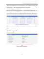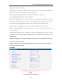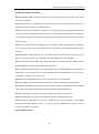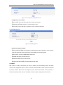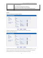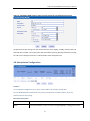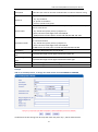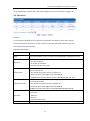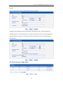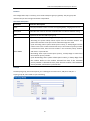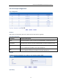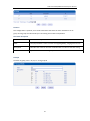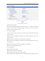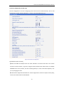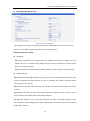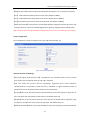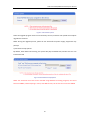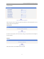
1
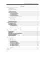
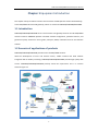
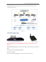
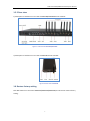
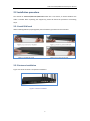
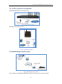
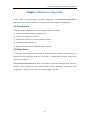
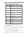
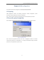
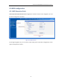
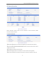
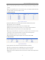
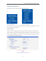
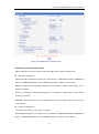
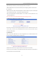
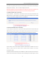
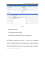
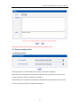
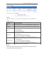
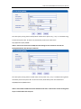
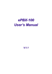
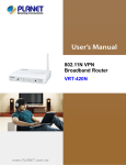
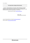
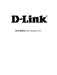
DWG Series GSM/CDMA VoIP Gateway User Manual (Version: 2.0) Dinstar Technologies Co., Ltd. Address: Floor 6, Guoxing Building, Changxing Road, Nanshan District, Shenzhen, China 518057 Telephone: +86 755 6130 2265 Fax: +86 755 2645 6659 Emails: [email protected], [email protected] Website: www.dinstar.com DWG Series GSM/CDMA VoIP Gateway User Manual Content Chapter 1 Equipment introduction ................................................................................................... 2 1.1 Introduction ........................................................................................................................ 2 1.2 Scenario of products........................................................................................................... 2 1.3 Product appearance ........................................................................................................... 3 1.4 Functions and features ....................................................................................................... 4 1.4.1 Protocol standards................................................................................................... 4 1.4.2 System functions ..................................................................................................... 4 1.4.3 Industrial Standards ................................................................................................ 5 1.4.4 General hardware specification .............................................................................. 5 1.5 Structure of product ........................................................................................................... 6 1.5.1 Front view ................................................................................................................ 6 1.5.2 Rear view ................................................................................................................. 7 1.6 Restore factory setting ....................................................................................................... 7 Chapter 2 Equipment installation ..................................................................................................... 8 2.1 Installation notice ............................................................................................................... 8 2.2 Installation procedure ........................................................................................................ 9 2.2.1 Install SIM card ........................................................................................................ 9 2.2.2 Antenna installation ................................................................................................ 9 2.2.3 Connect cable of equipment ................................................................................. 10 2.3 Establish remote login environment ................................................................................ 10 Chapter 3 Network configuration ................................................................................................... 11 3.1 Preparation ....................................................................................................................... 11 3.2 Attentions ......................................................................................................................... 11 3.3 General prefix code for private service............................................................................ 12 3.4 Static IP Configuration ...................................................................................................... 12 3.5 DHCP configuration .......................................................................................................... 13 Chapter 4 WEB configuration .......................................................................................................... 14 4.1 Preparation ....................................................................................................................... 14 4.2 log in WEB interface ......................................................................................................... 14 4.3 WEB configuration ............................................................................................................ 15 4.3.1 WEB introduce ....................................................................................................... 15 4.3.2 System Information ............................................................................................... 16 4.3.3 Network configuration .......................................................................................... 18 4.3.4 mobile configuration ............................................................................................. 22 4.3.5 System Configuration ............................................................................................ 32 4.3.6 Tools ....................................................................................................................... 45 Chapter 5 FAQ ................................................................................................................................. 48 Glossary .......................................................................................................................................... 50 1 DWG Series GSM/CDMA VoIP Gateway User Manual Chapter 1 Equipment introduction This chapter mainly introduces functions and structures of DWG (Dinstar wireless VoIP Gateway) series GSM/CDMA wireless VoIP gateways, which are named as DWG2001/DWG2004/DWG2008. 1.1 Introduction DWG2001/DWG2004/DWG2008 serial is full functions VoIP gateway based on IP and GSM/CDMA wireless network. DWG200X provides a flexible network configuration, powerful features, and good voice quality. It works for carrier grade, enterprise, SOHO, residential users for cost-effective solution. 1.2 Scenario of applications of products DWG2001/DWG2004/DWG2008 provides access of GSM/CDMA network. With the development of users and telecom service, mobile network and fixed network integration will be steadily increasing. DWG2001/DWG2004/DWG2008 provides high quality VoIP service. DWG2001/DWG2004/DWG2008 perfectly meets the requirement. This is a scenario shown as figure 1-1 2 DWG Series GSM/CDMA VoIP Gateway User Manual DWG2004/DWG2008 can be implemented as VoIP call termination in VoIP operation, the solution shown as figure 1-2 Figure 1-2 1.3 Product appearance Figure 1-3 Front view of DWG2004/DWG2008 Figure 1-4 DWG2001 Notes: DWG2004 equips 4 antennas, DWG2008equips 8 antennas; both models have the same appearance. DWG2001/DWG2004/DWG2008 serial supports GSM, CDMA network and frequency supported as below: GSM: Support quad-band 850/900/1800/1900MHz CDMA: Support 800MHz There are 3 models with DWG200X serial. Three models are shown in table 1-1: 3 DWG Series GSM/CDMA VoIP Gateway User Manual Model Network Type Interface DWG2001 GSM/CDMA 1WAN,1LAN ,1SIM channel DWG2004 GSM/CDMA 1WAN,3LAN, 4SIM channels DWG2008 GSM/CDMA 1WAN,3LAN, 8SIM channels Table 1-1 DWG2001/DWG2004/DWG2008 interface description 1.4 Functions and features 1.4.1 Protocol standard supported: Standard SIP and MGCP protocol; Simple Traversal of UDP over NATs (STUN); Point-to-point protocol over Ethernet (PPPOE); Hypertext Transfer Protocol (HTTP); Dynamic Host Configuration Protocol (DHCP); Domain Name System (DNS); GSM/CDMA; ITU-T G.711α -Law/μ -Law、G.723.1、G.729AB; 1.4.2 System function PLC: Packet loss concealment VAD: Voice activity detection CNG: Comfort Noise Generation Local/Remote SIM card work mode Adjustable gain of port DTMF adjustment Balance alarm Lock/unlock SIM/UIM Mobile number display rejection Sending/receiving SMS Customize IVR Recording White and black list 4 DWG Series GSM/CDMA VoIP Gateway User Manual One number access Open API for SMS, support USSD Echo Cancellation (with ITU-T G.168/165 standard) Automatic negotiate network Hotline 1.4.3 Industrial Standards supported: Stationary use environment: EN 300 019: Class 3.1 Storage environment: EN 300 019: Class 1.2 Transportation environment: EN 300 019: Class 2.3 Acoustic noise: EN 300 753 CE EMC directive 2004/108/EC EN55022: 2006+A1:2007 EN61000-3-2: 2006, EN61000-3-3: 1995+A1: 2001+A2: 2005 EN55024: 1998+A1: 2001+A2: 2003 Certifications: FCC, CE 1.4.4 General hardware specification Power Supply: DWG2001: AC100~240V 50/60HZ DC12V/1A DWG2004/DWG2008: AC100~240V, 50/60HZ Temperature: 0~40 ℃ (Operation), -20~80 ℃(storage) Humidity: 5%~90%RH, Power Consumption: DWG2001: 5W, DWG2004/DWG2008: 30W Dimensions: DWG2001: 112(W) x76(D) x24(H) mm DWG2004/DWG2008: 440(W) 305(D) x44(H) mm Net weight: DWG2001: 0.7kg, DWG2004/DWG2008: 5.0kg 5 DWG Series GSM/CDMA VoIP Gateway User Manual 1.5 Structure of product The appearance of A2001/DWG2004/DWG2008 serial shows in two views (front view and rear view). Figure 1-5 Front view of DWG2004/DWG2008 Figure 1-6 Front view of DWG2001 1.5.1 Front view There is variety of indicators on front view of DWG2001/DWG2004/DWG2008, its names and indications shown as table 1-2: Indicators Color Name PWR Green Power indicator RUN Green Occupancy indicator of Red channels Signal indicator Green Status Description Lighting Power is on Off Power failed Fast Blinking SIM cards Registered Slow blinking Unregistered Running indicator Indicate that occupancy Lighting status of channels Off GSM/CDMA signal strength indicator Used Un-used 3 grids Very strong 2 grids Strong 1 grid Weak Table 1-2 Description of indicators on front view of DWG2001/DWG2004/DWG2008 Note: No signal strength indicator on DWG2001 6 DWG Series GSM/CDMA VoIP Gateway User Manual 1.5.2 Rear view 1) Description of interfaces on rear view of DWG2004/DWG2008 shows as below: Figure 1-7 Rear view of DWG2004/DWG2008 2) Description of interfaces on rear view of DWG2001 shows as below: Figure 1-8 Rear view of DWG2001 1.6 Restore factory setting Push RST button for 6 seconds of DWG2001/DWG2004/DWG2008, the device will restore factory setting. 7 DWG Series GSM/CDMA VoIP Gateway User Manual Chapter 2 Equipment installation This chapter mainly introduces DWG2001/DWG2004/DWG2008 hardware installation and connection of equipment. 2.1 Installation notice DWG2004/DWG2008 used AC110~220V, 50/60Hz AC power supply, DWG2001 uses DC12V power. Power supply should ensure the reliability and stability; otherwise, it may damage the SIM card or device. In addition, make sure the power supply connects to ground bar well. With right ground protect connection, that can reduce the surge voltage caused by lightning that damage the equipment, and ensure voice quality (note: when calls with irregular noise occurring, please check the power whether connect ground well). Common measures are as follows: Making sure that all devices powered in the buildings are in accordance with NEC (National Electric Code, National Electrical Regulations) Article 250 of manual properly grounded; Making sure that the panel of building power supply units used high-quality copper wire well connect with the ground wire, copper wire specifications shall comply with NEC Table 250-94/95 relevant provisions of the manual. Grounding cable that buried in the building field, including at least one or several 2.44m deep under the ground, or buried deeply underground at least 0.76m, with a wire around the building (see NEC manual specifications the relevant provisions of the table 250-94/95); Setting up voltage protector between equipment and ground connected to some other computer equipments (either directly or through other devices), such as terminal or printer must also be plugged into the same surge protector. Network interface of DWG2001/DWG2004/DWG2008 supports RJ45 standard with 10Mbps or 100Mbps network. Wireless section, inserting SIM card directly, GSM channel should work properly. To check the network connection, user can monitor the registered status indicator (refer Table 1-2) 8 DWG Series GSM/CDMA VoIP Gateway User Manual 2.2 Installation procedure The outlook of DWG2001/DWG2004/DWG2008 looks like a 1U chassis; to install hardware the cable is needed. After unpacking the equipment, please do follow the procedure as following steps: 2.2.1 Install SIM card When installing SIM card, opening blank panel of SIM slot, procedure shows as below: 2.2.2 Antenna installation Figure 2-5 shows as below a compelete installation: Figure 2-5 Antenna installation 9 DWG Series GSM/CDMA VoIP Gateway User Manual 2.2.3 Cable connection of equipment DWG2004/DWG2008 works in Bridge mode DWG2001 works in Route mode Figure 2-7 DWG2001 connection 2.3 Establishing remote access Figure 2-8 Remote login environments After installation of DWG2001 /DWG2008, creating a remote access for technical support. 10 DWG Series GSM/CDMA VoIP Gateway User Manual Chapter 3 Network configuration In this chapter we will introduce the initial configuration of DWG2001/DWG2004/DWG200 gateway. All of the network parameters of the gateway can be configured by IVR guidance. 3.1 Preparation Please ensure the following stepes are done properly before IVR setting: 1) Prepare an analog telephone or mobile phone 2) Make sure the gateway is power on 3) Make sure the gateway is connected with the network 4) Completed the SIM installation 5) Make sure that the current mobile network is working 3.2 Attentions In each step, if user hears an IVR message of “setting successful”, which means that user has finished this step successfully. However, if user hears a “setting failed” message, please check redo theat step again. DWG2001/DWG2004/DWG2008 can work in two modes: route mode and bridge mode. when the gateway is under bridging mode, user should configure network parameters of WAN port; when the gateway is under the route mode, user should configure LAN port. 11 DWG Series GSM/CDMA VoIP Gateway User Manual 3.3 General feature codes for system setting Dial numbers Features *114# Play the phone NO. Check the TT number of gateway (using just when the *115# device interconnects with other series of DINSTAR products) Set IP address(static/DHCP), a can be digit 1 or 2,*150*1# is *150*a# static IP address mode, *150*2# is DHCP mode Configure IP address, a, b, c, d are the four fields of IP *152*a*b*c*d# address. Configure subnet mask. a, b, c, d are the four fields of the *153*a*b*c*d# subnet mask Configure the device gateway, a, b, c, d are the four fields of *156*a*b*c*d# the device gateway *158# Report the IP address Setting the work mode (route or bridge), * 157 * 0 # is route *157 mode, * 157 * 1 # is bridge mode *195# Play record *198# Clear record Setting Record. dial*199# start record(≤ 20s), then press # *199# end the recording *111# Restart device Table 3-1 Feature codes for system setting 3.4 Static IP Configuration This chapter introduces IP configuration of DWG2001/DWG2004/DWG2008 through calling IVR. Assuming the IP address of a DWG2001/DWG2004/DWG2008 device is 172.16.0.100, subnet mask is 255.255.0.0, IP of gateway is 172.16.0.1, configured as follows: 1) Insert a SIM card into the DWG2001/DWG2004/DWG2008 gateway 2) The configuration mode: Dial the phone number of this SIM card. hear a message, then enter “*150*1#”, hang up when hear “ setting successful" message; 3) Configure IP address: Dial the phone number of this SIM card, hear a message, enter "* 152 * 12 DWG Series GSM/CDMA VoIP Gateway User Manual 172 * 16 * 0 * 100 #" hang up when hear “setting successful" message; 4) configure subnet mask: Dial the SIM card phone number, enter "*153*255*255*0*0#" hang up when hear “setting successful" message; 5) Configure gateway: Dial the SIM card phone number, enter "*156*172*16*0*1#" hang up when hear “setting successful" message; 6) Please wait about ten seconds when finishing the operations, restart device. dial the SIM card phone number, enter “*158#”to check the Static IP address; 3.5 DHCP configuration DHCP mode configure as follows: 1) Insert a SIM card into a slot, dial the SIM card number. When hearing a hint message, then enter “*150*1#”, if hearing “ setting successful" message, which means the DHCP is confirued successfully; 2) Restart the device, wait for 30 seconds, and then dial the SIM card telephone number, enter "* 158 #" to query the IP address; Note: If reporting the IP address is 0.0.0.0, which means that the gateway could not obtain a IP address successfully. Please check: 1) Make sure the device have been connected to the network; 2) Make sure the DHCP Server is working. If there is no DHCP Server, please set the IP of device to static IP . 13 DWG Series GSM/CDMA VoIP Gateway User Manual Chapter 4 WEB configuration This charpter describes web configuration of DWG2001/DWG2004/DWG2008. 4.1 Preparing WEB configuration includes the following components: network configuration, system information, mobile configuration and system configuration. Dial “* 158 #” to get the IP address of the gateway, log on the web interface by a browser. 4.2 Access the system through http Enter IP address of DWG2001/DWG2004/DWG2008 in browser, and the GUI shows as below: Figure 4-2-1 WEB log interface Enter username and password and then click “OK” in configuration interface. The default username and password are “admin/admin”. It is strongly recommended, change the default password to a new password for system security. 14 DWG Series GSM/CDMA VoIP Gateway User Manual 4.3 WEB configuration 4.3.1 WEB Operation Guide DWG2001/DWG2004/DWG2008 WEB configuration interface consists of the navigation tree and the detail configuration interfaces. Figure 4-3-1 WEB introduce Go through navigation tree, user can check, view modify, and set the device configuration on the right of configuration interface. 15 DWG Series GSM/CDMA VoIP Gateway User Manual 4.4 System Information Figure 4-3-2 system information System information interface shows the basic information of status information, Mobile information and SIP information. 4.4.1 System information Figure 4-3-3 system information 【MAC Address】Displays the current MAC of the gateway, for example: 00-1F-D6-16-O3-7C; 【Network Mode】DWG2001/DWG2004/DWG2008 support two types network mode, which is bridge and route modes; 【Network】shows IP address and subnet mask. 【DNS Server】Displays DNS server IP address in the same network with the gateway. 【System Up Time】shows the time period of the device running. For example,:1h: 20m, 24s; 16 DWG Series GSM/CDMA VoIP Gateway User Manual 【Network Traffic Statistics】Calculates the netflow, including the total bytes of message received and sent. 【Version information】shows the current firmware version, for example EIA AOS 9.50.16 PCB 29.1 LOGIC 0 BIOS 1, Built on Sep 21 2010, 17:32:25; 4.4.2 Mobile information Figure 4-3-4 mobile information Display GSM / CDMA channel and network status information, detailed shown as below: 【Port】Numbers of ports of GSM/CDMA. 【Type】Indicates the current type of network. Such as CDMA or GSM 【IMSI】International Mobile Subscriber Identity, it is the uniquely identifies of SIM card. 【Status】indicates the connection status of current GSM / CDMA module. 【Remaining Call Duration】Limite a call duration to the SIM card, when call duration is out of that duration, the call would be discontinued. This option shows remaining talk time. 【Carrier】Displays the network carrier of current SIM card. 【Signal Quality】Displays the signal strength of in each channels of GSM / CDMA 4.4.3 SIP Information Figure 4-3-5 SIP information Displays registration status information with Softswitch platform or SIP Server 【Port】the corresponding number of GSM/CDMA channel, identify with 0-9 figure 【SIP User ID】SIP registration account of the Softswitch and SIP server provided 【Registered】 Shows the registration status of VoIP channels, including 2 state of registered and unregistered 17 DWG Series GSM/CDMA VoIP Gateway User Manual 4.5 Network Configuration The navigation tree of the route mode and bridge mode as below: Figure 4-3-6 bridge mode Figure 4-3-7 route mode In the navigation tree of route mode, will have extra items of “MAC Clone”,”DHCP Server” ,”DMZ Host” ,”forward Rule”,”Static Route” . 4.5.1 Local network Under the route mode, WAN port connects with ADSL modem, and LAN port connects with local network. It will be used as a small switch when working in brigde mode. In this situation, user just need to configure the WAN parameter and DNS. User also need configure the LAN port if working in route mode. The web interface as bellows: Figure 4-3-8 WEB interface of bridge mode 18 DWG Series GSM/CDMA VoIP Gateway User Manual Figure 4-3-9 WEB interface of Route mode Detailed parameters describled as below: 【Work mode】two options of route mode and bridge mode, default is bridge mode. Network Configuration 【Link Speed & Duplex】the 5 options are “Auto Detect”,” 10Mbps/Half Duplex”,”10Mbps/Full Duplex”, “100Mbps/Half Duplex” and “100Mbps/Full Duplex”. Default is “Auto Detect” 【Obtain IP Address Automatically】enable the device obtain IP Address automatically or not. Default is enabling 【Use the Following IP Address】configure the “IP Address”,” Subnet Mask” and “Default Gateway” by manual 【PPPoE】need ISP offer the account and password. Use this mode when have not router in the local network. LAN port configuration This option works when “route mode” is selected. 【Link Speed & Duplex】 the 5 options are “Auto Detect”,” 10Mbps/Half Duplex”,”10Mbps/Full Duplex”, “100Mbps/Half Duplex” and “100Mbps/Full Duplex”. Default is “Auto Detect” 19 DWG Series GSM/CDMA VoIP Gateway User Manual 【IP Address】set IP address by manual configuring. Default is 192.168.1.1 【Subnet Mask】set the lan port Subnet Mask by manual configuring, Default is 255.255.255.0 DNS Server 【Obtain DNS Server Address Automatically】When enable the WAN port option of “Obtain DNS Server Address Automatically” , which will be enabled subsequently. 【Use the Following DNS Server Addresses】fill in the IP address of “Primary DNS Server” and “Secondary DNS Server” Note: all the options in this interface can take effect after restarting the device 4.5.2 MAC Clone (configure this only when necessary) Figure4-3-10 Configuration of Mac Address Clone This function can prevent the device against blocking by the carriers. Enable this function on the “router mode”, the device can be anti-blocked when the carrier to limit the online users by scanning the MAC address. 4.5.3 DHCP Server Under “route mode”, DWG works as a router. Config DHCP serive to enable the DHCP service funcition of DWG, then DWG will works as a DHCP server. Figure 4-3-11 Configuration of DHCP service IP address Pool determines the range of IP addess of other devices in this network; IP Lease Time sets the duration for how long the IP works with the specific IP. If the duration is out of the duration, the IP would be invalid; 20 DWG Series GSM/CDMA VoIP Gateway User Manual The subnet mask, gateway, DNS info will also be allocated to network devices automatically by DHCP protocol. Generally, there is no need to configure those items. NOTE: Please configure the start and end IP addressed in IP address pool, subnet mask and gateway in the same network segment. Other devices in this network may not work when obtaining the IP address. 4.5.4 DMZ Host (Option under “route mode”) In some conditions, certain devices in LAN network need to do two-way communication with WAN network( e.g. certain computer in LAN network need to provide multiple services to WAN network). In this situation, Configure this device as the DMZ host. Figure 4-3-12 Configuration of DMZ Host 4.5.5 Forward rules (Option under “route mode”) In some conditions, certain devices in LAN network need to provide channel communication with WAN network( e.g. certain computer in LAN network need to provide FTP service of channel 21 to WAN network). In this situation, Configuring forwarding rules to this device is necessary. Figure 4-3-13 Configuration of forwarding rules Service channel is the one that should be provided to WAN network. IP address is the one of devices in LAN net work. The device needs to provide services. Protocol is the service protocol(TCP or UDP) The difference between forwarding rules and DMZ host is, DMZ host provides several consecutive channels and communication of all protocols, while forwarding rules provides single or several 21 DWG Series GSM/CDMA VoIP Gateway User Manual channels communication based on certain protocol(TCP or UDP). If DMZ host and forwarding rules have conflicts, will be determined by forwarding rules configurations. 4.5.6 Static route(Option under “route mode”) Static route is the route rules in IP communication. Generally speaking, no need to config static route. Configuring static route is necessary in such conditions: when several network segaments exist in LAN network and there’s certain application between these network segament. Please cancel “internet sharing” under “ Network configuration” first, then configure the “static route”. Figure 4-3-14 Configuration of Static route In commly use, please don’t configure static route. If static rule is wrong, the devices may not work. 4.6 Mobile configuration 4.6.1 Basic configuration Figure 4-3-15 Basic Configuration 22 DWG Series GSM/CDMA VoIP Gateway User Manual Configuration details are as below: 【Dial Tone Gain(Mobile Side)】it is the dial tone volume of call waiting, dial tone of mobile module when call out. Usually adopt the default configuration. 【Select Band】according to carrier’s band standards. Standards are as belows: GSM:850/900/1800/1900 MHz ; CDMA:800 MHz; 【Forward enable】enable the function of trunk call in for mobile phone user ID, that is, choosing one user ID of the SIM channels as the access No of DWG device. When several calls use the user ID at the same time, DWG gateway will do call transfer to other available channels. 【Forward master mobile】select this channel’s mobile phone No. as the one access No. 【Reject Incoming Calls】when enable this function, this channel can only be used to call out, can’t used to call in. 【Remote API Enable】 API is provided for third party development with DLL and IAD components. The API includes SMS sending and receiving, USSD sending and receiving. The default is “No” 【API Server Address】it is the remote IP address who uses API. This is an option when selecting “Yes” under “remote API enable”. 【API Server Port】it is the remote channel No. who uses API. This is an option when selecting “Yes” under “remote API enable”. 4.6.2 Mobile Figure 4-3-16 Mobile Configuration 23 DWG Series GSM/CDMA VoIP Gateway User Manual Configuration details are as below: 【Mobile Number】SIM card user ID of the channel. That must be configured when “one access No.” funciton enable. 【Enable Call Duration Limitation】this function is to limit the max call duration of channel. The max call duration is between 1 to 65535 minutes. 【Maximum Call Duration】defines a value by users. That will limit the SIM/UIM card’s total call duration. After the call duration excesses this value, no call will be initiative by this channel. The value range is 1-65535. If user doesn’t configure this value, Default is no max call duration limits for this channel. 【Free time to call】a minimum charging time (in seconds) is defined during which no charging is done at carrier side. If the conversation time is even shorter, the total call duration will not decrease. 【Mobile Number(Receiving Alarm) 】 the mobile phone No. which used to receive the alarm SMS. Users can get SMS report of SIM/UIM card status(SIM Remain Time) in DWG. 【Alarm Threshold(via SMS) 】when the SIM remain time is or less than this value, DWG will send the alarm SMS to remind the users of the SIM remain time. 【Port Description for Alarm】it is the identification mark of SIM/UIM card in the designated SMS report. The mobile phone No. of the SIM/UIM card is recommended to use as the port description for alarm, or any other string. 【SIM Remain Time】indicates the current sim remain time. It can’t modified. 【Restore time】recovers the SIM remain time to initial value, the Maximum Call Duration. 【CLIR】caller ID display restrict. This function is used to restrict the mobile phone No. By adding “#31” before the mobile phone ID, this funciton should be supported by carrier. 【Mobile Tx Gain】transits gain of the mobile module, from IP side to PSTN side. 【Mobile Rx Gain】receives gain of the mobile module,from PSTN side to IP side. 【Detect Reverse Polarity】this option for CMDA Reverse Polarity detection. Most CDMA operators don't offer polarity reverse . So VoIP to mobile, DWG2008 will connect soon. It doesn't wait mobile side answer. 4.6.3 SIM/UIM card lock 24 DWG Series GSM/CDMA VoIP Gateway User Manual Figure 4-3-17 Configuration of SIM/UIM Card Lock Configurations are as below: 【Select Port】select the Channel No. which need to be locked. 【SIM Card Lock】SIM card lock or unlock. Default is “No”. 【PIN Code】correct PIN code is needed to lock or unlock the SIM card. 4.6.4 PIN Management Figure 4-3-18 PIN Management Detailed description as below: 【PIN management】PIN is the password of SIM card personal identification. In the status of SIM card locked, PIN can be modified to prevent SIM card from being stolen. 【Select Port】selects the GSM/CDMA channel No. 【Old PIN code】the previous PIN code 【New PIN code】inputs a new PIN code 【Confirm New PIN Code】inputs the new PIN code again. 4.6.5 SMSC SMS center of mobile, theoretically, the celluar modular will automatically detect the SMSC number. This configurable option is used in a situation that the SMSC number could not detected by celluar modular. When such case happens, please contact with mobile service provider to identify the SMSC number and then add SMSC number in SMSC configurable web interface. 25 DWG Series GSM/CDMA VoIP Gateway User Manual 4.6.6 SMS Figure 4-3-19 SMS sending Configurations are as below: 【Select Port】users can select a defined channel or random channel to send SMS. Input the recevier’s mobile phone No to send SMS. 【Addressee】mobile phone No. of the receiver 【Message】content of the SMS. The length is limited to 300 characters. 4.6.7 USSD USSD (Unstructured Supplementary Service Data) is a Global System for Mobile(GSM) communication technology that is used to send text between a mobile phone and an application program in the network. Applications may include prepaid roaming or mobile chatting. USSD is similar with Short Messaging Service (SMS), but unlike SMS. USSD transactions occur during the session only. With SMS, messages can be sent to a mobile phone and stored for several days if the phone is not activated or within range. 26 DWG Series GSM/CDMA VoIP Gateway User Manual Notes:please check with local service provider before using this service. 4.7 Routing configuration 4.7.1 Routing parameter Globle parameters, it will take effect while number manipulation configured Route calls after manipulation: the parameters indicate that the gateway will select IP->Tel or Tel->IP routes after number manipulation completed. Route calls before manipulation: the parameters indicate that the gateway will select IP->Tel or Tel->IP routes before number manipulation completed. 27 DWG Series GSM/CDMA VoIP Gateway User Manual 4.7.2 IP->Tel Routing Function: When the softswitch/ sip server send the call traffic to gateway directly, must be added IP->Tel routing. Parameter Description Parameter Parameter Description Index It uniquely identifies a route. Its value is assigned globally, ranging from 0 to 31. Description It describes the route for the ease of identification. Its value is character string Source IP It specifies the source IP which will send the calls to gateway Any: any IP address IP: specific an IP address IP Group: specific an IP group Source Prefix All the caller number must match the source prefix. It specifies the source prefix allow to send call out Any: include anonymous, 0xxxx, 1[2-9]xxxx etc. 0xxxx: consist of some digits such as 015,08,09 1[3-8]6:consist of some prefix, include 136,146,156,166,176, 186 Destination Prefix All the called number must match the destination prefix, the call prefix indicates the connected number Any: include anonymous, 0xxxx, 1[2-9]xxxx etc. 0xxxx: consist of some digits such as 015,08,09 1[3-8]6:consist of some prefix, include 136,146,156,166,176, 186 Destination Its specifies destination Port or Port Group Example: Index 0 : add a route from VoIP to GSM, the calls coming from IP Group 18<asterisk> will call out thourgh destination Port Group 31<Unicom>. 28 DWG Series GSM/CDMA VoIP Gateway User Manual The caller party coming from IP Group 18 will match source prefix ”any”, ”any” is a wildcard string include anonymous calls. At same time, destination prefix must match with ” 13[4-9]xxxxxxxx|6xxx|10086”. Index 1: add a route from VoIP to GSM, the calls coming from IP 14<tribox> will call out through destination Port Group 31<Unicom> The caller party coming from IP 14 will match source prefix ”any”, ”any” is a wildcard string which will match prefix anonymous calls. At the same time, destination prefix must match with ” 15[0189]xxxxxxxx|188xxxxxxxx”. Index 2: add a VoIP to GSM route which allowed all the calls. It will receive all calls coming from any IP to destination Port Group 31 29 DWG Series GSM/CDMA VoIP Gateway User Manual Prefix ”any” is a wildcard string which will match anonymous calls as well. 4.7.3 Tel->IP Routing Function: This item uses to configure incoming call routes which can be used for recieve the calls from the GSM. Parameter Description Parameter Parameter Description Index It uniquely identifies a route. Its value is assigned globally, ranging from 0 to 31. Description It describes the route for the ease of identification. Its value is character string Source Port It specifies the Port or Port Group which will receive the calls from PLMN Source Prefix All the caller number must match the source prefix. It specifies the source prefix allow to send call out Any: include anonymous, 0xxxx, 1[2-9]xxxx etc. 0xxxx: consist of some digits such as 015,08,09 1[3-8]6:consist of some prefix, include 136,146,156,166,176, 186 Destination Prefix All the called number must match the destination prefix, the call prefix indicates 30 DWG Series GSM/CDMA VoIP Gateway User Manual the connected number Any: include anonymous, 0xxxx, 1[2-9]xxxx etc. 0xxxx: consist of some digits such as 015,08,09 1[3-8]6:consist of some prefix, include 136,146,156,166,176, 186 Destination Its specifies destination Port or Port Group Example: Index 0: its a default route configured in gateway It allows any number from source port 0 send call to SIP server with any prefix. Index 30: add a GSM to VoIP route It indicates that the calls coming from Port Group 31<Unicom> will match the prefix ”x.”, ”x.” is a wildcard string which will match any prefix except ”anonymous” calls. Meanwhile sending the calls destination IP 13<eia> if called number match with destination prefix ”00”. 31 DWG Series GSM/CDMA VoIP Gateway User Manual Index 31: add GSM to GSM route,its mainly used for saving the cost between two carriers It indecates that calls coming from Port 0 will match the prefix 13[58], ”13[58]” include prefix 135 and 138, caller number can’t match prefix 135 and 138 will reject by gateway. Meanwhile sending the calls to Port Group 31<Unicom> if called number match with prefix 133. 4.8 Manipulaton Configuration Function It is an optional configuration item, and is used to add IP->Tel number change data. The IP->Tel Manipulation defined the rules of add, and deletion of called numbers, which are referenced by IP->Tel routing. Parameter Description Parameter Parameter Description Index It uniquely identifies a route. Its value is assigned globally, ranging from 0 to 31. 32 DWG Series GSM/CDMA VoIP Gateway User Manual Description It describes the route for the ease of identification. Its value is character string Source IP It specifies the source IP which will send the calls to gateway Any: any IP address IP: specific an IP address IP Group: specific an IP group Source Prefix All the caller number must match the source prefix. It specifies the source prefix allow to send call out Any: include anonymous, 0xxxx, 1[2-9]xxxx etc. 0xxxx: consist of some digits such as 015,08,09 1[3-8]6:consist of some prefix, include 136,146,156,166,176, 186 Destination Prefix All the called number must match the destination prefix, the call prefix indicates the connected number Any: include anonymous, 0xxxx, 1[2-9]xxxx etc. 0xxxx: consist of some digits such as 015,08,09 1[3-8]6:consist of some prefix, include 136,146,156,166,176, 186 Destination Its specifies destination Port or Port Group Stripped Digits from It specifies the length of the digits to be deleted from left Left Stripped Digits from It specifies the length of the digits to be deleted from right Right Prefix to Add Add the new digits in front of the original number Suffix to Add Add the new digits at the end of the original number Example Add an IP->Tel Manipulation, to change the called number from 2547888888 to 07888888 It indecates that calls coming from IP Group will match the prefix ”any”, and the called nubmer 33 DWG Series GSM/CDMA VoIP Gateway User Manual whom match with the prefix ”2547” will delete 3 digits in front of it and replace it by digit ”0”. 4.9 Operation Function It is an optional configuration item. Operation configuration essentially involves allow, barring some IP and IP Group send calls to certain numbers. It includes: forbid call, call allowance, auto call, and password authentication. Parameter Description Parameter Parameter Description Index It uniquely identifies a route. Its value is assigned globally, ranging from 0 to 31. Source IP It specifies the source IP which will send the calls to gateway Any: any IP address IP: specific an IP address IP Group: specific an IP group Source Prefix All the caller number must match the source prefix. It specifies the source prefix allow to send call out Any: include anonymous, 0xxxx, 1[2-9]xxxx etc. 0xxxx: consist of some digits such as 015,08,09 1[3-8]6:consist of some prefix, include 136,146,156,166,176, 186 Destination Prefix All the called number must match the destination prefix, the call prefix indicates the connected number Any: include anonymous, 0xxxx, 1[2-9]xxxx etc. 0xxxx: consist of some digits such as 015,08,09 1[3-8]6:consist of some prefix, include 136,146,156,166,176, 186 Operation Description Its specifies number analysis rule Forbid call Allow call Auto call Password authenticate It describes the route for the ease of identification. Its value is character string 34 DWG Series GSM/CDMA VoIP Gateway User Manual Example Index 31: barring the certain calling number from IP 14<elastix> It indicates that calling party from IP 14<elastix> matched prefix 2877, and also called party matched prefix 07 are not allowed call out. The calls match this rule will be rejected by gateway. Index 29: definite a rule for IP 17<FreeSentral> that all the calls must go with valid password authentication. 4.3.8 Port Group Configuration 35 DWG Series GSM/CDMA VoIP Gateway User Manual Function This configuration step is necessary, and is used to add port group in gateway. The port group will referenced by IP->Tel routing and number manipulation. Parameter Description Parameter Parameter Description Index It uniquely identifies a route. Its value is assigned globally, ranging from 0 to 31. Description It describes the route for the ease of identification. Its value is character string Port It specifies the Port will add to port group Select Mode It specifies the policy for selecting port in a port group Ascending: the system always selects a port from the minimum number. The preferential selection of the port can be realized through this mode Cyclic ascending: when system selects ports’ Priority, it always begin from the number next to the number selected last time, if the maximum priority number is selected last time, then the next number is the minimum priority number, and move in cycles like this Descending: when system selects ports’ priority, it always begin to select from the maximum priority number Cyclic descending: when system selects ports’ Priority, it always begin from the number before to the number selected last time, if the minimum priority number is selected last time, then the next number is the maximum priority number, and move in cycles like this Example To add a port group, assume that port 6, port 7 belong to the same carrier, add port 6 and port 7 to port group 30, select mode is cyclic ascending. 36 DWG Series GSM/CDMA VoIP Gateway User Manual 4.3.9 IP Group Configuration 1) IP configuration Function Add remote IP of softswitch, SIP server which will send call traffics to gateway. Parameter Description Parameter Parameter Description Index It uniquely identifies a route. Its value is assigned globally, ranging from 0 to 31. Description It describes the route for the ease of identification. Its value is character string IP It is an interworking parameter between the remote Softswitch and the SIP server. It specifies the IP address of the peer equipment. Port It is an interworking parameter between the remote Softswitch and the SIP server. It specifies the SIP port number of the peer equipment Example To add a remote IP of Softswitch, set “index” to “31”, SIP port number “5060” 2) IP Group 37 DWG Series GSM/CDMA VoIP Gateway User Manual Function This configuration is optional, and is used to add the IP that have the same attributes to an IP group. The IP group will referenced by IP->Tel routing and number manipulation. Parameter description Parameter Parameter Description Index It uniquely identifies a route. Its value is assigned globally, ranging from 0 to 31. Description It describes the route for the ease of identification. Its value is character string IP It specifies the IP will add to IP group Example To add an IP group, set IP “10, 14, 17” to IP group 18 38 DWG Series GSM/CDMA VoIP Gateway User Manual 1) System configuration Figure 4-3-20 System Configuration Configuration details as below: 【Voice Prompt Language】configure the voice prompt of DWG., e.g. configure voice prompt of IP address success or failure. DWG supports English and Chinese. Users can customize other languages. The default setting is in Chinese. Provision configuration Provision is used to maintain the devices. E.g. Provision can config, update and remote manage the devices in bulk. 【Primary Provision Server IP】this is provided by carrier. Keep the default value if carrier don’t provide this value. 【Primary Provision Server Port】this is provided by carrier. Default is 80. 【Secondary Provision Server IP】this is provided by carrier. Keep the default value if carrier don’t provide this value. 【Secondary Provision Server Port】this is provided by carrier. Default is 80. 【Provision Check Interval】default is 4 hours. NTP Configuration 【Enable NTP】NTP enable switch 【Primary NTP Server IP】can keep the default 【Secondary Provision NTP Server IP】can keep the default 【Time Zone】the default is GMT +8:00, the user can adjusted accordingly according to their area 39 DWG Series GSM/CDMA VoIP Gateway User Manual 2) Service configuration (for SIP only) Service Configuration is used for configuring voice calls and some small businesses, such as Call Progress Tone, codec, silence suppression, * service, the second dial and so on Figure 4-3-21 Service Configuration Detailed description as follow: 【LOCAL RTP PORT Channel】means the initial allocation of Channel when RTP voice stream transmit in the IP network , in general, using the factory default values. When there are multiple DINSTAR series voice products, and the network gateway or router’s NAT with loopholes, user can try changing this item. 【Enable Silence Suppression】enable the "silence suppression" almost no impact on call quality, and can save about half of the bandwidth. 40 DWG Series GSM/CDMA VoIP Gateway User Manual 【Call Progress Tone】each country has its different call progress tone required standards, such as busy tone, ring back tones and ring tone standards, users can select the area standard from here . 【Preferred Coders】means the code format when Voice transfer on IP network, support PCMA, PCMU, G.723.1 andG.729AB. Note: when the preferred codec switch between G.723.1 and G.729AB , System will automatically reset 【Enable PSTN Incoming Configuration】 means when call from PSTN side, you can dial the function keys for check number, setting IP and so on function 【Enable Auto Outgoing Routing 】means when call out , whether by ordinal or polling pick to Select a Channel, this feature are generally used for when use the same SIP User ID to register or use as trunking mode 【IP to PSTN One Stage Dialing 】 this function will be displayed only when select "Enable Auto Outgoing Routing" function, the User ID will be sent directly to PSTN, for example: the user calls 6715, the device will sent 6715 User ID to PSTN 【Play Voice Prompt for PSTN Incoming Calls 】setting is yes, when through the PSTN calls to the Channel, the device will with the clew tone, the default is "Please dial the extension User ID"; setting to No, the device will with dial tone 【Send Original Caller ID for PSTN Incoming】for Example, the phone A from PSTN side call DWG2001/DWG2004/DWG2008 Channel SIM card corresponding User ID, the Channel's SIP User ID is C, Channel hook and then call B, when "Send Original Caller ID for PSTN Incoming" setting is Yes, the Caller User ID that send to B will be A, when "Send Original Caller ID for PSTN Incoming" setting is No, the caller User ID that sent to B will be C(except for anonymous outgoing ) 【 DTMF 】 DWG2001/DWG2004/DWG2008 support RFC2833 and SIGNAL two ways. DTMF INTERVAL range is 50 ~ 800ms, DTMF VOLUME can use the default Configuration 【Enable STUN】 (Simple Traversal of UDP over NATs,NAT’s UDP simple cross) is a network protocol. It is allowed to stay behind the NAT (or multiple NAT) client part to identify their clients’ public address, found himself after what Type of NAT and NAT for a particular Channel is bound to a local Internet terminal Channel. This information is used for two host to set up UDP communication behind the same NAT router. The agreement defined by the RFC 3489 41 DWG Series GSM/CDMA VoIP Gateway User Manual 【CLID Mode】Select the name under the special needs , the most common way is use the default User ID 【Other Configuration】 : Enable”*“at the beginning private internal service: the default is enable, that the private internal network-related service refer to Configuration query, recording, adjust the volume, restore the factory default values, etc. ; SIP request message whether with a user = phone: is a SIP protocol requirement, if the soft switch no require, setting is no; Only Accept Calls from SIP Server: is whether only accept the call from the SIP PROXY Server , if the setting is Yes, the call through point to point IP ADDRESS will be rejected (not launched from SIP server's address) ; “Allow Outgoing Calls without Registration”and “Allow Incoming Calls without Registration”need use together , which refer to "SIP Configuration" - "Is register" option, if”Is register" setting is no, this two options need set Yes ,to avoid that the devices can not call out ; “Allow Anonymous Outgoing Calls” setting to No, the device caller User ID is a registered User ID, setting to Yes, the device Caller User ID as "Anonymous" ; "Allow Anonymous Inbound" setting to No, the incoming anonymous calls will be rejected; “Use # as End Key”,in General, SIP phones are based on # as the end, if this option is set to No, the dial-up will end expires dial-up time; “Inter digit Timeout”Bit of between the dialing time ,over the time will be seem as end of dial-up; 42 DWG Series GSM/CDMA VoIP Gateway User Manual 3) SIP Configuration (for SIP only) Figure 4-3-22 SIP Configuration SIP Configuration: used for Configuring VoIP channel, add SIP Registry Platform and local SIP Channel, and configure SIP protocol and other related information Detailed description as follow: SIP PROXY 【SIP Server Address】use for configure SIP server address and Channel, the address can be IP Address, also can be a domain name (DNS should to be able to resolution), the details please advisory the service provider 【SIP Proxy Port】port default setting is 5060. For details, please consult the service provider Outbound Proxy 【Outbound Proxy Address】Outbound proxy, it mainly used in firewall / NAT environment. That make the signaling and media streams are able to penetrate the firewall, the details please advisory the service provider 【Outbound Proxy Port】outbound proxy port number, the details please advisory the service provider 【Use Random Port】set the local monitor SIP port(fixed or random), random is every time you start the device will random Select a free SIP port Monitor 【Is Register】 default set yes, if you want the device can make a call without register, set No, Also enable the "Allow Outgoing Calls without Registration" and "Allow Incoming Calls without Registration" function 43 DWG Series GSM/CDMA VoIP Gateway User Manual 【Register Interval】means how often the equipment will register once to the SIP server/proxy 【T1】 used to define the SIP protocol T1 timer value, default is 500ms; 【T2】 used to defines the SIP protocol timer values, default value is 4000ms; 【T3】used to define the T2 timer value in SIP protocol, the default is 5000ms; 【Keep alive Interval】used for keep communicate between equipment and the SIP server that make the device is in the best available Registered. In general, using the factory default values Note: all parameters refering to defaultt setting of SIP protocol, user can modify that if necessary 4) Port configuration Port Configuration is used to configure ports’ gain, Off-hook Auto-Dial, etc. Figure 4-3-22 Port Configuration Interface describe as following: 【ALL ports register used same user ID】 The default is not, each SIP account, if set yes ,all the port will use user ID of port0, when the call ring in sequence 【 SIP User ID】 is the account used for registration, equipment port's unique identifier, "Authenticate ID" is equivalent to show the name, "Password" is register Password, which no passward can no fill, the details please contact the service provider 【Tx Gain】refers to the call volume that from himself during a call to the end users, adjust the "Tx Gain" will affect the voice volume of the end user, the default value is 0 【Rx Gain】refer to the call volume from the remote end user to ourself volume, adjust the "gain acceptance" will affect the voice volume we will heard, the default value is 0. 【Offhook Auto-Dial】Hotline service.when PSTN part client calls to this port,will auto forward to 44 DWG Series GSM/CDMA VoIP Gateway User Manual the hotline User ID. If no need this feature, just left it blank 【Auto-Dial Delay Time】Offhook Auto-Dial delay time, the range is 0-10 seconds 5) Fax Configuration Figure 4-3-23 Fax Configuration Fax Configuration use for configure fax, and support pass-Through and T.38 fax mode, the maximum baud rate supported 14400bps Interface describe as following: 【Fax way】support T.38 and pass-Through; 【Fax Tone Detection Mode】There are two calling and called 【Enable ECM】Error Correction Mode. If enabled, when transmiss the fax ,will automatically detects the wrong part of the requested retransmission to eliminate data errors, but will increase the fax time 【Fax Rate】support fax rate list include:2400bps、4800 bps、7200 bps、9600 bps、12000 bps、 14400 bps 4.3.6 Tools 1) Firmware upload Equipment upgrades can through Dinstar’s softswitch platform, when the device disconnects with Dinstar’s softswitch platform or some special circumstances. The firmware is able to upload locally. 45 DWG Series GSM/CDMA VoIP Gateway User Manual Figure 4-3-24 firmware upload Select the upgrade program under correct directory services, and then click upload will complete upgrade the firmware. NOTE: during the upgrade process, please do not swtich off the power supply, equipment may paralyze. 2) IVR Voice Prompt Upload By default, when PSTN call incoming, the system will play the default IVR, and also the user can load custom IVR. Figure 4-3-25 IVR Voice Prompt Upload NOTE: the customize voice files can be recorded using Windows recording programs, the sound format is 8000Hz, 16 bit sampling in mono, with WAV format, size of files can not exceed 190KB 46 DWG Series GSM/CDMA VoIP Gateway User Manual 3) Login password Figure 4-3-25 IVR Voice Prompt Upload When using web or telnet Configuration, please enter default user name and password. User can modify the login name and password. 4) Factory Reset Figure 4-3-26 Factory Reset Be careful do this operation, after restore factory setting, all the parameters will be changed to the factory default. 6) Restart Figure 4-3-27 Restart When system restarts, user click RESET button on the web. 47 DWG Series GSM/CDMA VoIP Gateway User Manual Chapter 5 FAQ Device have been connected to network physically, but the network cannot be connected or network communication is not normal 1) Make sure the network cable is ok or not , can through view the device WAN port or LAN port indicator light to determine the physical connection is working or not; 2) Make sure the connected network devices (router, switch or hub) support 10M/100M adaptive, if not, connect the Equipment directly to PC, landing WEB and in the "local connection" Configuration interface Select the correct Ethernet Work Mode; 3) Check the Network Configuration, if the Configuration is incorrect, please re-Configuration. If you are using DHCP mode, check DHCP Server is working properly; 4) Check whether there is a LAN device conflict with the exists IP ADDRESS; Equipment cannot register If the Run LED does not flash mean unregistered 1) Check the network connection is working (see above section), whether the Configuration is correct; 2) Check whether the LAN firewall setting is inappropriate (such whether limit the network communication); If it is, there are two ways to try to resolve; 3) Ask network administrators to open limitation with the equipment’s network communications (it is a special equipment, not afraid of virus attacks); (2) try to enable the equipment tunnel (through the WEB for Configuration, Also, please NOTE, open the tunnel will impact voice quality, Please do not enable the tunnel as far as possible, reference WEB Configuration Interface Description section); 4) Check whether the Local Network to the SIP PROXY platform network environment is relatively poor or not, and if so, please check Local Network or contact the service provider; 5) if go through those steps, the device still be in trouble, please contact the equipment provider; 48 DWG Series GSM/CDMA VoIP Gateway User Manual When calling out, the callee’s phone shows wrong caller ID: 1) Ask the callee checks whether the device is failure or device battery power is low 2) Make sure the callee has been subscribed called User ID display service 3) If only part of the caller User ID with this problem, please contact the telecom carrier to identify the problem. when calling in, the caller always hears a busy tone Make sure Enable DND(Do-not-Disturb) in system sudden interruption during a call 1) make sure whether is human error caused the problem 2) Make sure with the account balance or lack of disruption caused the call disconnected 3) Make sure whether there is interference with the fax tone or equipment busy tone, these interference may lead to calls dropped 4) Make sure whether the LAN equipment such as gateway or router fails, user can try to restart the gateway or router voice single-pass, double-barrier or poor quality 1) Make sure the equipment is working properly with grounded power 2) Check the device network connection is in working status 3) Ask network administrators to open limitation with the equipment’s network communications (it is a special equipment, not afraid of virus attacks); (2) try to enable the equipment tunnel (through the WEB for Configuration, Also, please NOTE, open the tunnel will impact voice quality, Please do not enable the tunnel as far as possible, refer WEB Configuration Interface Description section) 4) Make sure the LAN equipment is working, user can try to restart the gateway or router to solve the problem 5) Check whether there is more than one DINSTAR series products in LAN network: some gateways or routers, processing network packet is vulnerable (for example, to multiple network devices or the same protocol network communication, NAT allocated the same conversion communications Channel). If there is such a case, suggest replacing a router or specify each voice gateway with different LOCAL RTP PORT Channel (refer to the base WEB 49 DWG Series GSM/CDMA VoIP Gateway User Manual Configuration interface section) 6) Check the equipment network environment for the softswitch platform, monitor the network condiation, make sure the network is solid Glossary GSM: Global System for Mobile Communications CDMA: Code Division Multiple Access FMC: Fixed Mobile Convergence SIP: Session Initiation Protocol MGCP: Media Gateway Control Protocol DTMF: Dual Tone Multi Frequency USSD: Unstructured Supplementary Service Data PSTN:Public Switched Telephone Network STUN: Simple Traversal of UDP over NAT IVR: Interactive Voice Response IMSI: International Mobile Subscriber Identification Number IMEI: International Mobile Equipment Identity DMZ: Demilitarized Zone 50