1
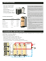
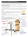
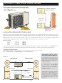
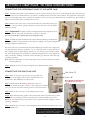
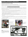
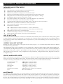
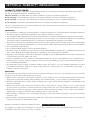
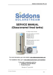
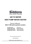
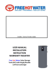
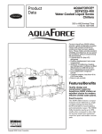
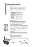
INSTALLATION AND USER MANUAL INSTALLERS Please read these instructions carefully before undertaking the installation of a Siddons Solarstream Heat Pump Water Heater Models Domestic: 264SSBD, 327SSBD www.siddonssolarstream.com Version 2.4 06/12 SPECIFICATIONS: HEAT PUMP SPECIFICATIONS: INSTALLATION RECOMMENDATIONS: 230~240 V, ac, 50 Hz, 1.38 Kw Supplied with 3 pin 10 amp Plug Weight 39 kg Sound level 53dBA Operational temp range -50 ~ 450C Diameter of airflow outlet 400mm Refrigerant R417A Heating capacity @200C =100L / hr Size L,795mm W,255mm H, 540mm Whilst there is no specific need for any external weather protection for the Solarstream Heat Pump Water Heater, if shelter is available such as an overhanging eave, it is a good idea to use it. The Heat Pump unit is designed to be installed outside. In cold conditions it will produce a lot of condensate water from the evaporator. This needs to drain away with out causing any damage to the surrounding building or material. CYLINDER SPECIFICATIONS: 327SSBD 264SSBD Capacity 327 Litres 264 Litres A Height 1980 mm 1620 mm B Diameter 580 mm 580 mm C Hot water outlet 1491 mm 1136 mm D Cold water inlet 186 mm 168 mm Dry weight 73 Kg 62 Kg Inlet water pressure 500 kPa Water connections P&T Valve (supplied) C 500 kPa D 20mm ~ 3/4 BSP B 850kPa A The location of the tank and Heat Pump is flexible. Good design considerations should be given to: 1. Position the water tank in close proximity to bathroom and kitchen area to reduce heat waste. 2. Minimise the distance between Water Tank and Heat Pump unit for efficiency. 3. Position the Heat Pump unit to maximise any sun, ambient warm or reflected heat from wall or building. COMMERCIAL INSTALLATIONS: Solarstream units can be single units or coupled together in many combinations from 3 to 6 units for energy efficient light commercial installations. Typical Commercial Examples Are: Gymnasiums, Fitness Centres, Health Spas Aged Care Facilities, Medical Centres, Hair Salons Kindergartens, Day Care Centres, Play Centres Hostels, Backpackers, Motels Complexes, Caravan Parks Manufacturing Facilities, Commercial Buildings, Bars, Restaurants Outdoor Heat Pump Units Hot Water pipes must be fully insulated to reduce heat loss hot water manifold thermostat controls pressure and temperature relief valves Hot Water take off circuits tempering valve Return Water drain Refrigerant lines cold water manifold EQUAL PRESSURE MANIFOLD DESIGN 1 tempered circuits SECTION 1: PLUMBING INSTALLATION A licensed plumber should install the Solarstream. It is the installers responsibility to comply with all AS/NZ Standards, Building Codes and Trade Codes of Practice for compliant installations of domestic hot water heaters. In Australia, your plumber should also hold a Restricted Split System Air Conditioning Installation and Decommissioning License (Certificate II course under the Australian Refrigeration Council’s code RSS03) covering air conditioning and heat pump split systems. WATER TANK INSTALLATION As the Solarstream does not require a sacrificial anode, the headroom above the cylinder only needs to accommodate convenient installation rather than the one metre or more required to remove/replace the anode. Therefore, the Solarstream water tank can be comfortably installed inside or outside of your house in a tight space with little headroom, although the Heat Pump unit should be installed outside. It is best to install the Water Tank close to the outlet that has the greatest usage of hot-water, such as the laundry or bathroom. Ensure adequate access for service to the Thermostat and Pressure and Temperature (P&T) relief valve. Ensure the specification label is visible. Installation must comply with Australian Standard AS/NZS 3500.4 and any local authority regulations. OUTDOOR For outdoor (external) installations, a plinth or concrete base pad is recommended in accordance with Australian Standard AS/NZS3500.4 to properly support the Solarstream water tank such that the water tank is assured of remaining in a vertical position throughout its usable life and not lean over due to possible erosion of soil under the plinth, or such risk. SIESMIC RESTRAINT Some building codes require Seismic Restraint of storage water heaters to be adequately supported against earthquake forces. You should consider restraining the tank to a wall with Stainless Steel bands. FILLING Fill the Water Tank by opening all hot-water taps and opening the cold-water inlet to allow air in the system to be expelled. Close each hot-water tap; as the flow becomes free of air, check all pipes for any signs of leaks. Power should not be turned on until the Water Tank is completely filled with water. EXAMPLE OF TYPICAL MAINS PRESSURE HOT WATER SYSTEM INSTALLATION (Please note, your plumbing may vary from this diagram, we recommend discussing your requirements with your plumber prior to installation) 1200mm (minimun distance) Pressure Limiting & Stop Valve with filter or similar valve arrangement. Set at 500kPa Notes: 327SSBD model has a ring main return port just above mid tank. This should be blocked off with a 3/4 BSP plug. Water control valves are not supplied with the Solarstream unit. Ring main return port Only on model SSAD327 (If needed) Cold Water Expansion Valve 700kPa A drain must be included to allow full and complete draining of the Water Tank 2 Pressure & Temperature Relief Valve (850kPa) supplied with Solarstream. It is recommended that hotwater outlet pipes are fully insulated with weather proof insulation such as Armaflex. The hot-water outlet pipe should be angled down at about 150 minimum for the first 250mm after exiting from the Water Tank outlet. This will create a heat trap that will avoid any thermal siphoning from the Water Tank. A PRESSURE LIMITING VALVE MUST BE FITTED TO ENSURE THE INCOMING WATER IS NO GREATER THAT 500kPa SECTION 2: HEAT PUMP INSTALLATION Clear space clearance around outdoor unit. • Locate the heat pump away from combustible material • Inlet - 200mm clear air • Outlet - 1000mm clear air Installation limitations height and distance Heat Pump Unit can be installed on first floor roof. Max of 5 mtr from base of Cylinder 5 mtrs max hot water outlet cold water inlet Heat Pump Unit can be installed up to 8 mtr from cylinder Max length of pre-charged interconnecting pipes is 9 mtrs INSTALLATIONS REQUIRING EXTENSION LINES Standard unit has 2 mtrs of refrigerant line connected to the Heat Pump unit. Considering bends and connections, this allows the Heat Pump unit and Water Tank to be installed to a distance apart as shown (Drwg A). (This is intended as a guide only.) Many installations will require the Heat Pump outdoor unit and the Water Tank to be positioned further apart than the standard unit configuration allows. In these installations, an extension line kit needs to be used. Extension line kit. 1.5 mtr 3.0 mtr 5.0 mtr 7.0 mtr order code order code order code order code 150SSBX 300SSBX 500SSBX 700SSBX These extension line kits come fully insulated, pre-charged and include the longer thermostat cable e.g. a 300SSBX has a 6 mtr thermostat cable to replace the standard 3 mtr Thermostat cable (1 metre longer than the refrigerant lines). MAXIMUM DISTANCE APART The maximum length of refrigerant line to be connected to the Heat Pump is 9 metres. E.g. 2 metre standard + 7 metre extension = total 9 metres max. REFRIGERANT LINES IN DUCTS, WALLS OR SURFACE MOUNTED (Drwg A) TANK TO LEFT TANK TO RIGHT In most installations the refrigerant lines will be surface mounted. They should always be protected in PVC surface trunking designed specifically for air conditioning systems. If the refrigerant lines are to be installed in a wall cavity or through timber framing they need to be installed by notching the timber. It is not possible to fit the line couplers through a hole less than 90mm diameter. Refrigerant lines run underground must be enclosed in a 100mm PVC pipe. An extension kit should be used and run through the pipes prior to Installation. It is ver y difficult to get the refrigerant lines through ducting and bends after installation. Standard unit with 2mtrs of refrigerant lines 3 SECTION 3: HEAT PUMP TO TANK CONNECTIONS CONNECTING THE REFRIGERANT LINES TO THE WATER TANK Step 1. Carefully unwind the copper refrigeration pipes on the heat pump, take care to avoid kinking the pipes. The pipes are quite hard copper and will kink if care is not taken to carefully mould or form the curve required. If a tight bend to the right is required in the refrigeration lines, cut back the insulation and use a soft copper tube bender to form the bend. The insulation must be taped back in place once the bend is made. Step 2. Remove the lower cover on the tank, find the two male refrigeration pipe couplers; you may need to gently pull them out from the tank if you find them difficult to access. Step 3. Important! Feed the couplers and refrigerant lines through the holes in the cover plate to align with the respective couplers on the tank. You cannot undo the couplers later if you forget this step. Step 4. Carefully align the male & female couplers before tightening, misalignment can cause rupture or displacement of the internal “O-Ring” seal, causing refrigerant leakage & defective performance. Use some mineral oil on the threads and rubber O-Ring and ensure the coupling nuts are fully tightened using two spanners, one on each half of the coupling then draw the coupling halves together tightly; please note you will feel some resistance when the metal diaphragms are punctured to facilitate refrigerant flow; keep tightening until you feel the “O-Ring” seal fully seated otherwise gas will leak under the high operating pressures. Note: There should be little or no thread showing on the connectors when the couplers are fully tightened. Step 5. Refit the lower cover plate and tighten the 4 Stainless Steel screws. CONNECTING THE HEAT PUMP UNIT Side Cover “A” Step 1. Remove the side cover “A” by removing screw “B”. Pull the cover out slightly at the bottom and push the cover downwards a few millimetres to release tabs. Screw “B” Step 2. Check that the flare fittings (Note A) on the line connectors are still very tight to ensure no gas leakage here. (If they are loose, the line may have leaked gas and could need service.) Step 3. Remove the cover caps on the refrigerant gas valves. Step 4. Open the refrigerant gas flow valves at the base of the heat pump using a 5mm hex key. Turn both large and small valves fully anti-clockwise until they stop hard. Note: We recommend using soapy water on the couplers and flare fittings to check gas leaks. (Note A) Step 5. Replace the cover caps on the refrigerant valves and refit the plastic side cover to the Heat Pump unit. Open the refrigerant gas valves only once you have checked the connections are all made correctly and are tight. 4 Note (A) Check flare fittings are tight before opening valves SECTION 4: ELECTRICAL INSTALLATION CONNECTING THE ELECTRICAL SYSTEMS The Solarstream is designed for single phase 230~240 V A.C. 50 Hz supply, max load 1400 watt. Australian Standard AS/ NZ 3000 or AS/NZ 3006 Wiring Code and local supply authority regulations apply. The Heat Pump should be plugged into standard day rate power points, or alternatively arrangements may be made with an electrician to have the power lead directly wired into an off-peak supply at the main circuit board. Allow for a 10 amp power supply with circuit breaker. The Solarstream does not have an electrical booster element. The Solarstream is supplied with a thermostat on the side of the Water Tank, behind the upper cover, to regulate the water temperature and a manual reset, over-temperature safety cut-out located on the side of the Heat Pump to protect the Heat Pump; these devices regulate the water temperature. Under no circumstances, should the Solarstream be operated without both of these devices being in circuit. The wiring loom connection between the Heat Pump and the Water Tank is standard 3 metres in length, designed for 230~240 volt ac power. It is a 1.5 mm 2 cable, protected in UV resistant flexible conduit. Fit the wiring loom through the cable hole in top inspection cover on the Water Tank and secure with the conduit gland and lock nut. Ensure the conduit gland is tight so cable cannot pull out. Heat Pump connection: Connect the screw down spade lugs to the heat pump thermostat connection terminal, and the earth wire to the earth lug as in Fig A below. Water Tank connection: Connect the push on connectors to the tank thermostat and the earth wire to the earth lug as in Fig B below. It is recommended that cable ties be used to tie the wiring loom to the refrigerant lines. Where refrigerant line extension kits are used (refer page 4) these kits are supplied with matching extension thermostat wiring looms. Never attempt to join or extend a Solarstream wiring loom. Do not connect the thermostat directly to an external power outlet. The power source must be derived from the Heat Pump via the wiring loom. Replacement of the wiring loom should be undertaken only by a qualified electrician or authorised Solarstream service technician. A wiring diagram is located inside the plastic side cover of the heat pump (a detailed wiring diagram is located under heat pump lid for maintenance). Fig B: Thermostat Connection Thermostat Connection onto terminals 1 & 2 Earth to Earth lug Push on connectors Earth to Earth lug Ensure earth connection is tight. Thermostat cable inserted and secured under cable clamp. HEAT PUMP WIRING DIAGRAM Fig A: Heat Pump Connection BL 5 NOTE: WATERPROOF SOCKET OUTLETS RD RD 3 NO 2 RL 6 RD RD Use only a high quality IP53 rated weather protected switched socket outlet. 5 SECTION 5: TROUBLE SHOOTING INSTALLERS AND SYSTEM CHECKS Commissioning Heat Pump unit is securely fastened to prevent tipping over. Water Tank is totally secure and cannot tip over. Water Tank is plumbed correctly, bled of air and full of water. Pressure and temperature relief valve is working. (Perform a manual release test) Refrigerant lines are mechanically protected against possible impact or damage. All refrigerant gas lines are free of any kinks or twists. All couplers and flare nuts are tight with no gas leaks. (Perform soapy water test) All Tank and Heat Pump covers are back in place and tight. Condensate water spilling from the Heat Pump outdoor unit will not cause any problems. 240V Power is connected and switched on at the socket outlet. Unit is electrically earthed, copper pipe work is earth bonded. Thermostat is connected: 230 ~ 240 V between neutral and terminal 1 (power to thermostat) 230 ~ 240 V between neutral and terminal 2 (power return from thermostat) Refrigerant gas valves open on Heat Pump unit. Check the Heat Pump continues to run for at least 20 minutes on first start up. Warm water should be evident at hot taps in about 60 minutes. LOSS OF HOT WATER Check firstly that the Heat Pump is connected to an electrical outlet and that power is available at the outlet by testing it with another electrical product. If the Heat Pump is connected to the controlled water heater wiring, then your electricity supplier may have the hot water supply switched off due to high demand or power load scheduling. You can check by calling your electricity retailer. WATER IS WARM BUT NOT HOT Recheck hot water in several hours, it may just have been heavy usage, or a cool ambient temperature which has affected hot water recovery performance. The Solarstream seems to be operating for too long each day up to 4 hours at times under normal domestic family use? It is likely that your refrigerant levels are too low, you may even have a slow gas leak. You will need to contact a Refrigeration Mechanic and ask them to check for gas leakage and re-gas your unit. The gas charge in the whole Solarstream system without extension lines should be 1.5kg of refrigerant (1.34 kg Heat Pump, 130 grams Water Tank, 30 grams 2 metre pair of refrigerant lines). HEAVILY MINERALISED WATER Where a Solarstream is connected to a water supply from unfiltered or highly mineralised water sources such as a spring, dam, bore, river or other natural ground sources, we require that the water be tested. Where water stored in the Water Tank exceeds the following characteristics an issue with corrosion may occur and void the water tank warranty. Total dissolved solids Total hardness Chloride Magnesium Sodium Electrical Conductivity pH 600 mg/litre or parts per million 200 mg/litre or parts per million 250 mg/litre or parts per million 10 mg/litre or parts per million 150 mg/litre or parts per million 850 µS/cm (micro siemens per centimetre) Min 6.5 and Max 8.5 MAINTENANCE For optimal long term performance, we recommend that you periodically check the fin coils of the evaporator and remove any material deposits restricting air flow with a brush or high pressure garden hose. Annually, we recommend operating the Pressure and Temperature relief valve (located at the top of the tank near the hot water outlet) by gently raising and lowering the lever. We recommend that you check with your plumber whether you need to drain and flush your tank periodically to remove possible sediment build-up inside the tank, depending on your local water quality. If so, follow the plumber’s instructions. 6 SECTION 6: WARRANTY INFORMATION WARRANTY COVER PERIOD The components of the Solarstream Heat Pump Water Heater are covered under warranty for the following periods from the date of despatch from Siddons Solarstream Pty Ltd: 10 years warranty on the Water Tank in domestic applications, 5 years in commercial applications 4 years warranty on the Heat Pump compressor in domestic applications, 2 years in commercial applications 3 years warranty on other parts of the Heat Pump in domestic applications, 2 years in commercial applications 1 year warranty on the Thermostat and P&T relief valve in domestic and commercial applications Labour on all warranty claims is covered for the first year, with a travel allowance for servicing of all warranty claims limited to two hours maximum, time only CONDITIONS: The Solarstream is installed by a licensed plumber or authorised technician in accordance with the installation instructions. All relevant statutory requirements applicable to the installation address are observed. The Solarstream Water Tank must be operated and maintained in accordance with instructions supplied in this manual. The warranty only applies to the Solarstream product and does not apply to any additional modifications not specifically endorsed by Siddons Solarstream Pty Ltd nor any electrical or plumbing parts supplied by the installer. The system is covered for the indicated period from the date of the original purchase. Should a part of the complete Water Tank component be replaced during this period, only the balance of the original warranty will continue to remain effective Proof of purchase will be required. The Solarstream Water Heater is used for its intended purpose. Should this system be installed in a regional location where regular flushing is required due to sediment build-up, then the drain cock for flushing must be fitted at the time of installation. If in doubt consult your plumber. Regarding a site investigation, where the Solarstream is installed more than 50 kilometres from an Authorised Dealer, the cost of travelling may be charged to the owner. Siddons Solarstream Pty Ltd is excluded to the extent allowable by law from responsibility for any consequential loss including: injury to persons, injury to property, economic loss, pain and suffering or legal or other damages flowing from any manufacturing fault/defect. The Heat Pump should operate in weather conditions within the range of -5ºC cold weather temperature and 45ºC hot weather temperature. Operation outside of this range may void warranty cover on Heat Pump components including compressor and labour. EXCLUSIONS: The following warranty exclusions may cause the Solarstream warranty to become void, and which may incur a service charge and cost for parts should this become necessary: Where service is required to reconnect the operation of the Solarstream due to problems related with abnormal water supply such as high water pressure, faulty plumbing and/or electrical wiring, or major variations in electricity supply. Where the system fails due to misuse, accidental damage, flood, acts of God, incorrect installation or unlicensed service repair work attempts. Where water stored in the water tank is mineralised from sources such as a spring, dam, bore, river or other natural ground sources and exceeds our minimum mineral content criteria (set out in “Heavy Mineralised Water”, page 6). Where there are claims for damage to wall foundations (outside), furnishings (inside), rooves or other losses, directly or indirectly due to leakage of water from the Solarstream tank or outdoor HP unit. Where damage or breakage is not covered by this warranty, and should be added separately to your general household insurance policy. Where benefits conferred by this warranty are additional to other rights and remedies in respect of the product, which the purchaser has under local Trade Practices Laws. Register your Purchase of Siddons Solarstream on-line: www.siddonssolarstream.com We suggest you register your Solarstream via our web site to ensure we have all of your details required for prompt and efficient service should you ever have a problem. 7