1
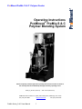
ProMinent ProMix ‘S & C’ Polymer Feeder Operating Instructions ProMinent® ProMix-S & C Polymer Blending System Please completely read through these operating instructions first! Do not discard! The warranty shall be invalidated by damage caused by operating errors! ProMix_S_OM.docx (03/01/13): – P/N: 7746719 (Revision D) ProMinent Fluid Controls, Inc. (USA) 136 Industry Drive, Pittsburgh, PA 15275 Tel: (412) 787-2484 ProMix Series_S & C User Manual www.prominent.us 1 Fax: (412) 787-0704 ProMinent ProMix ‘S & C’ Polymer Feeder TABLE OF CONTENTS Introduction i. Overview ................................................................................................................................. 3 ii. ProMix Systems ......................................................................................................................... 4 iii. ProMix Polymer Pump used on S & C Models ........................................................................ 6 1.0 Installation & Quick Start Guide 1.1 1.2 1.3 1.4 1.5 1.6 Safety ......................................................................................................................................... 7 Delivery & Storage Checklist .................................................................................................. 7 Installation Considerations ......................................................................................................... 7 Installation Guidelines............................................................................................................. 8 Quick Start Guide ................................................................................................................... 9 Servicing Guidelines ............................................................................................................... 10 2.0 Controller 2.1 2.2 2.3 2.4 2.5 2.6 2.7 2.8 2.9 2.10 2.11 2.12 2.13 2.14 2.15 2.16 Keypad Navigation ................................................................................................................ 11 Main Menu ............................................................................................................................. 12 Adjust Setpoint ..................................................................................................................... 13 Modify Timing ........................................................................................................................ 14 Flush Mixer ............................................................................................................................ 16 Status Message Summary .................................................................................................... 17 Calibrate 4-20 mA Input ........................................................................................................ 18 Scale the 4-20 mA Input ........................................................................................................ 19 Response on Loss of 4-20 mA Input ..................................................................................... 21 Calibrate 4-20 mA Output ....................................................................................................... 22 Adjust Pump............................................................................................................................. 23 Keypad Menu Overview ........................................................................................................... 24 4-20 mA & Frequency Controls ............................................................................................... 25 Troubleshooting Guide ............................................................................................................ 25 Diagnostic Display .................................................................................................................. 26 Blue White A-100NV Pump ................................................................................................. 27 3.0 Spare Parts & Preventive Maintenance 3.1 3.2 3.3 3.4 3.5 Blue White A-100NV Pump Spare Parts ................................................................................ 28 PVC Mixing Chamber Spare Parts .................................................................................................. 28 Piping Components Spare Parts ............................................................................................. 28 Control Panel Spare Parts ..................................................................................................... 28 Maintenance and Lubrication Schedules............................................................................... 29 Appendix A. B. B.1 B.2 B.3 C. D. TA Series Bill of Material ......................................................................................... 30 Control Panel “A Controls” Controller Board Layout .......................................................................................................... 39 Controller wiring (TA Series) P/N: 7746568 .......................................................................... 40 4-20 mA Input Scaling ......................................................................................................... 41 Polymer Sizing/Dosage ............................................................................................................... 42 Reference Documents............................................................................................................................................ 43 ProMix Series_S & C User Manual 2 ProMinent ProMix ‘S & C’ Polymer Feeder INTRODUCTION i. Overview: The ProMix S & C “TA Series” Polymer Feeder is a skid system designed to control feed water and polymer and combine them to produce a high quality solution. The system is designed to receive liquid neat polymer while mixing it with feed water to produce and discharge a quality solution from the system. Research in the science of polymer activation indicates that the activation energy must decrease as the polymeric chain is uncoiled to prevent rupture and hence decrease the performance of the product. The mixing of the Polymer Feeder is accomplished mechanically with three distinct mixing zones separated by baffles. The first zone consists of a fast mixing blade that delivers high shear at the precise point of polymer injection, creating and immediate dispersion before agglomeration takes place. The second zone mixing blade induces a vortex and draws solution down through the center of the chamber from zone one and forces the solution outward to the sides and then down into zone 3. Finally, the third zone mixing blade gently agitates/blends the active polymer solution before it exits the chamber through the bottom of the discharge tube. Zone 1 Zone 2 Zone 3 Direct Dire Coupled Motor Pipe Connections P Solution Exit The ProMix Polymer Feeder can be enabled in local mode (Simple On/Off operation) or remotely via a customer supplied dry contact which will Stop/Start the ProMix S Polymer Feeder. A H-O-A manual switch on the door of the controller permits the user to select the Manual mode by turning the switch to ‘H’, the Auto mode by turning the switch to ‘A’ or Off by selecting ‘O’. Either mode can be turned on or off remotely via a customer permissive contact. In Manual mode the H-O-A switch is placed into the ‘H’ position on the controller door of the ProMix Polymer Feeder. The neat polymer pump speed is then adjusted manually using the controller keypad to change the pump rate from 0 to 100% of the pump rated output. The user must calculate the required pump speed based upon the polymer concentration desired after manually adjusting the primary and secondary rotameters for the desired dilution water flow. The ProMix is designed for a maximum capacity of 0.5% polymer concentration. In Auto mode the H-O-A switch is placed into the ‘A’ position on the controller door of the ProMix Polymer Feeder. This offers a remote control option. In this mode, the controller receives a remote customer supplied analog 4-20 mA signal to adjust the desired pump speed from 0 to 100% of the pump rated output. This remote 4-20 mA signal can be scaled at the controller to enhance the resolution of the pump output control and bias the pump response to the remote signal. As in the Manual mode the user must calculate the required pump speed to attain the desired dosage. The ProMix Polymer Feeder is equipped with all the necessary components for easy installation, reliable performance and safe operation. The design incorporates an electric solenoid valve (water inlet), flow meter/switch, manually adjustable rotameters for primary and secondary dilution flow, peristaltic neat polymer pumps, microprocessor based controller, manual ball valves, pump calibration column, PVC piping and components, and polymer mixing chamber mounted on a skid to facilitate proper mixing and delivery. ProMix Series_S & C User Manual 3 ProMinent ProMix ‘S & C’ Polymer Feeder ii. ProMix Systems: ProMix S Systems consist of the following skid models: Peristaltic Pump Type Blue-White (A-100NV Series): PART NUMBER MODEL PUMP TYPE MAX CAPACITY 7747048 ProMix S 60-0.24TA Blue White A100NV 0.24 GPH 7747049 ProMix S 60X2-1.06TA Blue White A100NV 1.06 GPH 7747050 ProMix S 180X2-1.06TA Blue White A100NV 1.06 GPH 7747051 ProMix S 180X2-2.22TA Blue White A100NV 2.22 GPH 7747052 ProMix S 300X2-2.22TA Blue White A100NV 2.22 GPH 7747053 ProMix S 300X2-4.14TA Blue White A100NV 4.14 GPH **Refer to Appendix C for proper sizing** Overall Skid Dimensions ........................................................................... 60”H x 30”W x 24”D Overall Weight of Skid .................................................................................................. 150 lbs. Power Requirements ............................................................ 120VAC, 60Hz, 1 Phase, 15 Amp Volume of Mixing Chamber ..................................................................................... 2.0 Gallons Maximum Chamber Pressure .....................................................................................150 PSIG Normal Operating Pressure ....................... 50 PSIG or 65 PSIG (Depends on Pump Selected) Recommended Running Temperature .............................................................. +50°F to 100°F Water Connection Size ................................................................................................¾” FNPT Solution Discharge Connection Size ...........................................................................¾” FNPT ProMix Series_S & C User Manual 4 ProMinent ProMix ‘S & C’ Polymer Feeder ProMix C Systems consist of the following skid models: Peristaltic Pump Type Blue-White (A-100NV Series): PART NUMBER MODEL PUMP TYPE MAX CAPACITY 7747054 ProMix C 60-0.24TA Blue White A100NV 0.24 GPH 7747055 ProMix C 60X2-1.06TA Blue White A100NV 1.06 GPH 7747056 ProMix C 180X2-1.06TA Blue White A100NV 1.06 GPH 7747057 ProMix C 180X2-2.22TA Blue White A100NV 2.22 GPH 7747058 ProMix C 300X2-2.22TA Blue White A100NV 2.22 GPH 7747059 ProMix C 300X2-4.14TA Blue White A100NV 4.14 GPH **Refer to Appendix C for proper sizing** Overall Skid Dimensions ..................................................................42.75”H x 20”W x 22.25”D Overall Weight of Skid .................................................................................................. 107 lbs. Power Requirements ............................................................ 120VAC, 60Hz, 1 Phase, 15 Amp Volume of Mixing Chamber ..................................................................................... 2.0 Gallons Maximum Chamber Pressure .....................................................................................150 PSIG Normal Operating Pressure ...................... 50 PSIG or 65 PSIG (Depends on Pump Selected) Recommended Running Temperature .............................................................. +50°F to 100°F Water Connection Size ................................................................................................¾” FNPT Solution Discharge Connection Size ...........................................................................¾” FNPT ProMix Series_S & C User Manual 5 ProMinent ProMix ‘S & C’ Polymer Feeder Polymer Pumps used on S & C Models: Series Part Number Ident Code RPM Max A-100NV A-100NV A-100NV A-100NV 7747012 7747013 7747014 7747015 A1N00V-1T A1N30V-1T A1N30V-2T A1N20V-3T 14 60 60 45 Flowrate (GPH) Min Max 0.012 0.053 0.111 0.207 0.24 1.06 2.22 4.14 Pressure (PSIG) 65 65 65 50 Notes: 1. 2. 3. 4. 5. Blue White Peristaltic Pumps GPH Rating pumping Water not Polymer Power Requirements: 120VAC, 60Hz, Single Phase (0.35 Amp) Amps) Suction Lift Capabilities: 30ft. (Water) Tubing: Tygothane ProMix Series_S & C User Manual 6 ProMinent ProMix ‘S & C’ Polymer Feeder 1.0 INSTALLATION & QUICK START GUIDE 1.1 Safety: Utilize appropriate protective safety gear when operating or maintaining this equipment. Recommended safety gear is as follows: Personal Protective Equipment (PPE): Hard Hats (Where overhead hazards exist) Safety Glasses with side shields PVC Apron PVC Gloves Safety-Toed Work Boots 1.2 Delivery & Storage Checklist: 1. Check packing list for completeness and note any missing items immediately. 2. Inspect equipment and shipping container for damages before accepting delivery. Make note of the carrier’s bill-of-lading the extent of the damage, if any, and notify the carrier. 3. Store the equipment on firm level surface in original packing container. Do not store the equipment where it may be exposed to extreme temperatures, precipitation, humidity, or dust. Avoid direct sunlight that could overheat and damage equipment. Ambient Conditions for storage and transport: Temperature: 14°F to 120°F Air Humidity: ≤ 92% relative humidity, non-condensing 1.3 Installation Considerations: Required Polymer System Voltage Available Water Pressure Injection Point Pressure Number of Injection Points Polymer Solution Discharge: For example (Length of Piping Run and Pipe Size) Neat Polymer Suction: Flooded or Lift Type of Application / Dewatering Device Type of Polymer: Emulsion, Dispersion, Solution ProMix Series_S & C User Manual 7 ProMinent ProMix ‘S & C’ Polymer Feeder 1.4 Installation: 1. Unpack and position equipment on sturdy level surface. Fasten to prevent movement. 2. Do not install equipment in areas of extreme heat, cold, dust or humidity. Avoid areas where objects or fluids can drop from overhead. 3. Units are to be installed as close to the point of application as possible. 4. Inlet pressure is not to exceed 100 psig working pressure. 5. System pressure at the discharge is not to exceed 80% of inlet pressure. 6. Piping Internal to the System: Inspect the piping for breakage. The system may have been jarred during shipping. Check the tightness on all unions. Hand tighten only – no tools. Unions incorporate an oring seal. Ensure that the o-ring is seated properly prior to tightening. 7. Piping External to the System (Reference Appendix A for connection location): Install piping so that connections properly meet system termination points. Do not “stretch” field installed piping to meet system termination points. Stressed piping will fail! Piping should be at a minimum ¾” to and from the piping on the system. Avoid getting dirt and debris inside the piping during installation. Plug ends of piping with rags if construction activities are underway. All debris must be flushed from piping before system start-up. Connect to outlet piping ¾” FNPT from static mixer to associated customer application point. Connect to make-up water inlet piping ¾” FNPT (5 GPM maximum at 100 psig maximum). Connect to Neat Polymer pump inlet piping ½” FNPT. Install ¾” pressure regulator and ¾” y-strainer / basket strainer on the clean make-up water line if equipment is currently not installed. (Recommended) Allow provisions for draining the system piping. Skid components will require maintenance. Ensure that chemicals can be evacuated from the skid piping and components for servicing. 8. Electrical Supply Needed for the System: Note: Review local Electrical Code and follow accordingly. Connect incoming power to skid mounted control panel (120VAC, Single Phase, 15 Amp, 60 Hz). Ensure panel is properly grounded. Check electrical connections to be sure proper voltage is supplied to the system. Power the unit using a dedicated, separate breaker in the local lighting distribution panel. Do not route the AC power in common conduit with variable frequency pump drives. Do not put conduit entries in the top of the control panel. Resulting conduit condensation and failure to seal may damage controller circuit boards. 9. Set initial Chamber Mixer Motor Overload at approximately 2 Amps above the mixer FLA (Full Load Amps) rating and adjust as needed during startup to prevent nuisance tripping. 10. Connect Digital Remote Start Functions (note wiring termination points in Appendix B) for polymer tank level and remote start permissive. Default jumpers should remain in place for any input not available. 11. Refer to the Blue White A-100NV Installation & Maintenance Manual regarding pump information. ProMix Series_S & C User Manual 8 ProMinent ProMix ‘S & C’ Polymer Feeder 1.5 Quick Start Guide: 1. After the installation guidelines (Section 1.4) of the manual. 2. Open ball valve on the suction of the pump to allow chemical to flow into the system by gravity. If the application is suction lift then ensure liquid is present in pump suction. 3. Start up pumps at 100% stroke length and frequency to purge all air and prime the system. To prime the pump press and hold the PRIME button on the keypad until chemical is visible in the suction line. 4. Verify motor rotation on Mixing Chamber motor. Normal rotation is CCW. 5. Do not run the mixing chamber motor dry. Damage to the mechanical seal could occur. 6. Close the Secondary flow control valve and adjust the Primary flow control valve to obtain the flow range required. If additional dilution water is needed adjust the secondary accordingly. 7. Verify that the maximum polymer injection pump pressure is higher then the system pressure. 8. Perform pump calibration using drawdown calibration cylinder. 9. Check flow calibration and be sure pump meets or exceeds the rated flow capacity. Check flows at 100% capacity. 10. In Manual “Hand” mode the neat polymer pump speed is adjusted manually using the controller keypad to change the pump rate from 0 to 100% of the pump rated output. 11. In Auto mode the controller receives a remote customer supplied analog 4-20 mA signal to adjust the desired pump speed from 0 to 100% of the pump rated output. This remote 4-20 mA signal can be scaled at the controller to enhance the resolution of the pump output control and bias the pump response to the remote signal. A remote start permissive is also needed. If not available jumper these connections. 12. Confirm proper operation of all instrumentation. For example: Gauge, Rotometer switch, etc. 13. Input functions checked and simulated (remote start/stop, 4-20mA, etc.). 14. Output functions checked. 15. Test the operation of all remaining circuits. 16. Observe system to assure that nothing looks or sounds abnormal. ProMix Series_S & C User Manual 9 ProMinent ProMix ‘S & C’ Polymer Feeder 1.6 Servicing Guidelines: Disconnect electrical power to the equipment prior to servicing. Relieve all pressure from the unit prior to servicing. Close all suction and discharge valves. Verify dilution water is closed. Drain chemical/water from unit prior to disassembly. Maintain protective covers over all moving parts. Keep body parts, hair and foreign objects from contact with moving parts. Do not allow grease or oil to be used or stored around the feed equipment or chemicals. Review the Material Safety Data Sheets of the Polymer utilized and observe appropriate safety measures. Mineral Oil can be utilized to aid in the polymer cleaning process. Ensure all operating & maintenance personnel are instructed regarding the contents of this manual. ProMix Series_S & C User Manual 10 ProMinent ProMix ‘S & C’ Polymer Feeder 2.0 CONTROLLER 2.1 Keypad Navigation The ProMinent ProMix S Polymer Feeder uses a fixed configuration to deliver the operation required to operate the feeder. The main board is not interchangeable with other ProMinent controller hardware. The top line of the main menu displays the current feeder state on power ON Press EXIT during any main menu display & you’ll return to the top of the menu & the current feeder state. The other main menu displays show information you’ll need to set & adjust feed rate and to verify flowswitch, 4-20mA in & out… UP & DOWN to view options or to EDIT numbers ProMix Series_S & C User Manual 11 Move RIGHT to select next field when EDITing ENTER to select an option & to execute EDITing EXIT to escape option, info display or EDITing EXIT goes to top of Main Menu ProMinent ProMix ‘S & C’ Polymer Feeder 2.2 Main Menu This is the power ON, top of the menu display. Press EXIT at any display to return here. Displays the Polymer feed rate 0-100% and the current state of the feeder. See 1.6 for complete state table. Displays the Polymer Pump feed rate 0-100% and the controlling 4-20mA current level, Press ENTER @ Polymer Pump to view-adjust the Manual Setpoint & Calibrate the 4-20mA controlling the pump. Mixer ON time resets to zero every time the Mixer turns OFF. Press ENTER during Auto RUN or Manual RUN to turn OFF the Polymer Pump and flush the mixer. Polymer Pump ON 38% 10.1mA Mixer ON 49.1 Mins Mixer Flush on ENTER The Remote Setpoint 4-20mA current loop controls the Polymer Pump in Auto RUN mode. Press ENTER to calibrate. Flowswitch ON time resets to zero every time the Flowswitch turns OFF. After 24 hours displays >1Day. Alternates every second Polymer 38.6% Auto RUN The Remote Start contacts must be closed for the polymer feeder to run. Remote Start time resets to zero every time the contact set opens. We’re now back at the top of the main menu. Remote Setpoint 38% 10.1mA Flowswitch ON 3.45 Hrs Remote Start ON 1.36hrs Polymer 38.6% Auto RUN Sidebar: Press ENTER at Polymer to view and adjust feeder Fill, Flush & Wait-for-Flow timing. Press ENTER & UP at Polymer to view feeder Diagnostics. Refer to 4.2 for Diagnostic displays. Press ENTER & UP at Polymer Pump to view-modify the pump maximum SPM. Applicable only for feeders NOT using a 4-20mA, current loop controlled pump. ProMix Series_S & C User Manual 12 ProMinent ProMix ‘S & C’ Polymer Feeder 2.3 Adjust Setpoint Press ENTER @ Polymer Pump to view or adjust the Manual Setpoint. Manual Setpoint may be adjusted at any time in Auto or Manual mode. The present Manual Setpoint is 25.0%. Press ENTER to adjust. Key RIGHT to move the cursor & UP or DOWN to change the digit. Key EXIT to abandon or ENTER to execute. Adjust Manual Setpoint Polymer Pump ON 38% 10.1mA Manual Setpoint 25.0% Edit & ENTER 32.4% then Displays new, adjusted Manual Setpoint. Press EXIT to return to main menu. Manual Setpoint 32.4% If the Auto-Manual switch is in the Manual position, any adjustment takes effect immediately, modifying the 4-20mA output. Sidebar: Manual Setpoint only controls the polymer pump when the Auto-Manual switch is @ Manual. If the Manual Setpoint is @ 25% and the Auto-Manual switch is @ Manual, the 4-20mA current output loop will be at 8mA (4mA + 0.25 x 16mA = 8mA). ProMix Series_S & C User Manual 13 ProMinent ProMix ‘S & C’ Polymer Feeder 2.4 Modify Timing View Timing Press ENTER @ Polymer to view or adjust the feeder timing. Polymer 38.6% Auto RUN Fill Time may be adjusted to any time from 1 to 60 seconds. Press ENTER to adjust. Fill Time 30 Seconds or Flush Time may be adjusted to any time from 1 to 120 seconds. Press ENTER to adjust Flush Time 60 Seconds or Wait for Flow may be adjusted to any time from 1 to 30 seconds. Press ENTER to adjust. Diagnostics displays the input current loop power voltage. Press ENTER to view diagnostic data set. Refer to 4.2 for detail. Wait for Flow 5 Seconds or Diagnostics 23.9 VDC Sidebar: Fill Time: Water inlet solenoid open, ON. Mixer and Polymer Pump both OFF. Factory default = 30 seconds. Flush Time: Water inlet solenoid open, ON and Mixer ON. Polymer Pump OFF. Factory default = 60 seconds. Wait for Flow: Water inlet solenoid open, ON. Mixer and Polymer Pump both OFF. Factory default = 5 seconds. The 4-20mA current loop control input may be powered by the site control system or by the ProMix S 24VDC power supply. ProMix Series_S & C User Manual 14 ProMinent ProMix ‘S & C’ Polymer Feeder 2.4 Modify Timing (continued) Adjust Timing Press ENTER @ Polymer to view or adjust the Fill Time, Flush time or Wait for Flow time. All three times are adjusted in the same way. In this example we’ll press ENTER @ Fill Time. Fill Time 30 Seconds Key RIGHT to move the cursor & UP or DOWN to change the digit. Key EXIT to abandon or ENTER to execute. Polymer 38.7% Auto RUN Edit & ENTER 45 Seconds then Displays new, adjusted Fill Time. Press EXIT to return to main menu. Fill Time 45 Seconds Low Limit response If you ENTER a time less than 1 second, the Fill Time will be set to 1 second. High Limit response If you ENTER a time greater than 60 seconds, the Fill Time will be set to 60 seconds. Sidebar: Fill Time: Minimum = 1 second, Maximum = 60 seconds. Factory default = 30 seconds. Fill Time 1 Seconds Flush Time: Minimum = 1 second, Maximum = 120 seconds. Factory default = 60 seconds. Wait for Flow: Minimum = 1 second, Maximum = 30 seconds. Factory default = 5 seconds. ProMix Series_S & C User Manual 15 Fill Time 60 Seconds ProMinent ProMix ‘S & C’ Polymer Feeder 2.5 Flush Mixer Flush Mixer Press ENTER @ Mixer When the Mixer ON time display is alternating with the Flush on ENTER display. Mixer ON 49.1 Mins Alternates every second Mixer Flush on ENTER The polymer feed pump will turn OFF. The Mixer & water inlet solenoid will remain ON while the alternating Mixer display counts down the flush period. At the end of the Flush period the ProMix S will return to the Auto RUN or Manual RUN state unless the user: 1. Sets the Auto-Manual-OFF switch to OFF. 2. Shuts off the feeder inlet water. 3. Opens the Remote Start contacts. Sidebar: Flush Time: Minimum = 1 second, Maximum = 120 seconds. Factory default = 60 seconds. ProMix Series_S & C User Manual 16 Mixer ON 50.8 Mins Alternates every second Mixer Flush 26sec ProMinent ProMix ‘S & C’ Polymer Feeder 2.6 Status Message Summary LCD Displays Feeder State Offline STOP Feeder powered. Manual-Off-Auto switch at Off. Lin<4mA, Fault Flow Check No Water STOP Filling Mixer No Ext.Run STOP Flushing Mixer Flush Fail STOP Auto RUN Manual RUN Flushed, Stopped Press to Run Manual-Off-Auto switch at Auto and 4-20mA input less than 4 mA. Exits on 4-20mA >= 4 mA or Manual-Off-Auto = Off or Manual Waits user set seconds for Flowswitch contact set closed after Filling Mixer. Exits on flowswitch closed or Manual-Off-Auto = Off Exits on flowswitch closed or Manual-Off-Auto = Off Inlet Solenoid ON & Mixer OFF. Waits user set seconds to fill mixer. Exits on Manual-Off-Auto = Off Polymer Pump, Mixer and Solenoid OFF Exits on Remote Start contacts closed or Manual-Off-Auto = Off Solenoid & Mixer ON. Polymer pump OFF. Exits on flush time expired or No flow or Manual-Off-Auto = Off No Flow measured while flushing. Exits on flush time expired or flow measured or Manual-Off-Auto = Off Polymer pump @ 4-20mA input controlled setpoint. Exits on no flow, control<0%, flush, Remote Start open, or Manual-Off-Auto = Off or Manual. Polymer pump @ user setpoint. Exits on no flow, flush, Remote Start open or Manual-Off-Auto = Auto or Off. Flush ends. Polymer Pump, Mixer and Solenoid OFF Any key press restarts. Sidebar: Flow Check: The flowswitch measures dilution water flow into the mixer chamber. Filling Mixer: The mixer chamber is filled once after every power ON. If you drain the mixer, switch the power OFF then ON to re-fill the mixer chamber. ProMix Series_S & C User Manual 17 ProMinent ProMix ‘S & C’ Polymer Feeder 2.7 Calibrate 4-20mA Input Calibrate 4-20mA In Press ENTER @ 4-20 mA Input to calibrate the 4-20mA current loop input from the site’s control system 4-20 mA Input may be calibrated at any time in Auto or Manual mode. The present 4-20 mA Input is 38.7%. Press ENTER to calibrate. Key RIGHT to move the cursor & UP or DOWN to change the digit. Key EXIT to abandon or ENTER to execute. Remote Setpoint 38% 10.1mA Calibrate Iin 38.7% Edit & ENTER 36.9% then Displays new, adjusted Remote Setpoint. Press EXIT to return to main menu. Calibrate Iin 36.9% If the Auto-Manual switch is in the Auto position, any adjustment takes effect immediately and modifies both the 4-20mA output and the flashing green frequency output. Sidebar: ‘Calibrate Iin’ matches the % display on the polymer feeder with the remote operator’s % display. The underlying 4-20mA level is of less importance than having both of the % displays (the feeder’s & the remote operator’s) match because the Polymer feed pump operates from OFF at 0% to maximum ON at 100%. It’s simpler to calibrate on a % instead of calibrating on a current and making a non-intuitive 4-20mA loop to 0-100% conversion. So you don’t need to know that a 32.4% feed corresponds to a current loop @ 9.18 mA. The factory default scales the 4-20 mA input for 4mA = 0% Pump to 20 mA = 100% Pump. See Section 2.2 if your site’s 4-20 mA input is not scaled 4-20 mA = 0 to 100% ProMix Series_S & C User Manual 18 ProMinent ProMix ‘S & C’ Polymer Feeder 2.8 Scale the 4-20mA Input 4-20mA input sub Menu Press ENTER @ 4-20 mA Input to navigate the input current loop sub-menu See the previous page for calibrating the 4-20 mA input loop Press DOWN to view the present 4 mA pump feed percentage. The factory default is as displayed. When the 4-20 mA input is at 4.0 mA the pump will be OFF. Press DOWN to view the present 20 mA pump feed percentage. The factory default is as displayed. When the 4-20 mA input is at 20.0 mA the pump will be 100%. 4-20mA Input 38% 10.1mA Calibrate Iin 38.7% or Scale Iin @4mA 4.0mA = 0% or Scale Iin @20mA 20.0mA = 100% or Press DOWN to view the response when the input current loop is less than 4.0 mA. The factory default is as displayed. When the 4-20 mA input is less than 4.0 mA the pump will be OFF. Iin Fail State Pump OFF Press ENTER at any of the four sub-menu displays to modify the present setting. Press EXIT to leave unchanged. Sidebar: Calibration of the 4-20 mA input ensures that the measured value of the 4-20 mA Input is displayed as the correct mA level. Scaling the 4-20 mA input is required when you do not want 4-20 mA to correspond to a 0100% polymer feed rate. Selecting a different response than Pump OFF on loss of the 4-20 mA input allows for a wider range of site operational configurations & control loop reliability. ProMix Series_S & C User Manual 19 ProMinent ProMix ‘S & C’ Polymer Feeder 2.8 Scale the 4-20mA Input (continued) Modify mA @ 100% ON Press ENTER @ 4-20mA Input to calibrate the 4-20mA current loop input from the site’s control system. Press UP or DOWN to the Scale lin @20mA display & then press ENTER. Press RIGHT to move the underline cursor & UP or DOWN to modify the value @ the cursor. Press EXIT to leave the present setting unchanged. You can modify either or both of the mA level and the resulting pump feed %. Press ENTER when finished editing. Displays new, adjusted Scale lin @20mA Press EXIT to return to main menu. 4-20 mA Input 38% 10.1mA and Scale Iin @20mA 20.0mA = 100% Edit & ENTER 09.5mA = 100% then Edit & Enter 09.5mA = 45% Scale Iin @20mA 9.5 mA = 45% Edit either or both mA & % Scale lin @4mA is modified in the same way. Sidebar: There’s a lot of flexibility in the 4-20 mA input scaling & the corresponding pump speed but most users will leave 4mA=0% and adjust the mA @ 100% to allow 0-100% pump operation over a narrower range of 4-20 mA input. For example, if you wish 0-15% of the 4-20 mA input to control the pump from 0-100% Edit Scale lin @20mA for 6.4mA = 100% & leave Scale lin @ 4 mA unchanged at 4.0mA = 0% Setting the mA level below 4.0mA will set the mA level to 4.0mA Setting the mA level above 21.0mA will set the mA level to 21mA Setting the % above 100% will set the % to 100%. The % level cannot be set below 0%. Refer to Appendix A for notes on 4-20mA Input scaling. If you set % span to zero in error, the pump will turn OFF. Note that you could make the current loop response reverse acting so that an increasing loop current will cause a decreasing pump %. ProMix Series_S & C User Manual 20 ProMinent ProMix ‘S & C’ Polymer Feeder 2.9 Response on Loss of 4-20 mA Input View-Modify response On 4-20mA Input fail Press ENTER at 4-20Ma input. Press UP or DOWN to lin Fail State. Displays the factory default. Pump OFF when 4-20mA Input less than 4mA. Press ENTER to select a different response. Press DOWN to select a user set pump speed on less than 4 mA. Displays the factory default of 10%. Press ENTER to select response & modify value. Press DOWN and ENTER to run the pump at the last input Value greater than 4.0mA when the measured current loop value falls below 4.0mA. . If you pressed ENTER @ Pump @ 10% You will be able to modify the 10% value. 4-20mA Input 38% 10.1mA and Iin Fail State Pump OFF Pump OFF Pump @ 10% Pump @ 10% Last good Iin Last good Iin Pump OFF ENTER @ Pump @ 10% Press RIGHT to move the underline cursor & UP or DOWN to modify the value at the cursor. Edit & ENTER Pump @ 26% then Press EXIT to leave unchanged or ENTER To set the new value. Iin Fail State Pump @ 26% Sidebar: The feeder defines a failed 4-20mA input @ -1% which is nominally 3.85mA. (4.0mA – 0.01 x 16.0mA = 3.84mA) 3.85mA allows 4.0mA, a valid pump control signal some headroom prior to a fault response ProMix Series_S & C User Manual 21 ProMinent ProMix ‘S & C’ Polymer Feeder 2.10 Calibrate 4-20mA Output Calibrate 4-20mA Out Press ENTER & DOWN @ Polymer Pump to calibrate the 4-20mA current loop output that controls the pump feed rate The present Polymer Pump control is 38.0% But the on-pump display is @ 39.5% Press ENTER to calibrate. Polymer PUmp ON 38% 10.1mA and Calibrate Iout 38.0% Key RIGHT to move the cursor & UP or DOWN to change the digit. Key EXIT to abandon or ENTER to execute. The ProMix S reduces the pump 4-20mA current So that the on-pump display will measure 38.0%. Press EXIT to return to main menu. Edit & ENTER 39.5% then Calibrate Iout 38.0% Any adjustment takes effect immediately and modifies both the 4-20mA output and the flashing green frequency output. Sidebar: ‘Calibrate Iout’ matches the % display on the polymer feeder with the polymer feed pump’s % display ( not all pump types display %, some display mA ) Note: 50% will not display 12mA after calibration. It will display the mA required for the pump to display 50% which could be 11mA to 13mA Refer to 4.3 for 4-20mA reset. Correction >10% blocked, displays “Advice >10% Adj.Error”. Press EXIT to clear. Modifying Zero, <4% At less than 4% the 4-20mA zero is modified to correct loop offset. Example: Pump shows 0% and the ProMix S displays 1.5%. Modifying Span, >6% At more than 6% the 4-20mA span is modified to correct loop gain. Example: Pump shows 52% and the ProMix S displays 50% ProMix Series_S & C User Manual 22 ProMinent ProMix ‘S & C’ Polymer Feeder 2.11 Adjust Pump Adjust Pump Press ENTER & UP @ Polymer Pump to view or modify the maximum pump stroke rate. Ignore this page if you are controlling the pump using the feeder 4-20mA current output. Polymer Pump ON 38% 10.1mA and The present Polymer Pump is rated @ 240 SPM Press ENTER to modify. Key RIGHT to move the cursor & UP or DOWN to change the digit. Key EXIT to abandon or ENTER to execute. Adjust Pump 240 SPM Edit & ENTER 120 SPM then Displays new, adjusted Polymer Pump maximum strokes-per-minute. Press EXIT to return to main menu. Adjust Pump 120 SPM Any pump speed adjustment takes effect immediately, modifying the flashing green frequency output rate. Sidebar: The above only applies to custom ProMix S & C systems equipped with optional diaphragm metering pumps utilizing frequency (pulsing) control. Feeders using frequency controlled pumps can intentionally limit the pump polymer feed rate at the 100% manual and auto setpoints by reducing the pump maximum SPM. No effect on 4-20mA controlled Pumps Changing the pump maximum SPM has no effect on the 4-20mA current loop output. ProMix Series_S & C User Manual 23 ProMinent ProMix ‘S & C’ Polymer Feeder 2.12 Keypad Menu Overview Fill Time 30 seconds Polymer 38.6% Auto RUN Edit & Enter 30 seconds Polymer Pump ON 38% 10 mA Manual Setpoint 2.5% Edit & Enter 5 seconds Flush Time 60 seconds Edit & Enter 60 seconds Mixer ON 49.1 Mins Calibrate Iout 0.0% Edit & Enter 0.0% Wait for Flow 5 seconds Edit & Enter 5 seconds Diagnostics 23.9 vdc Mixer Flush on ENTER Adjust Pump 200 spm Edit & Enter 0.0% Serial Number Remote Setpoint 38% 10 mA Remote Start ON 1.36 hrs Mixer ON 49.1 Mins 24 v External 24.3 vdc Firmware Ver. 41410 Mixer Flush 26 sec Watchdog resets Flowswitch ON 3.45 hrs Power OFF ONs 7 Calibrate I in 36.2% P R W M S _ _ _ _ _ Edit & Enter 36.2% Pump ON Days hrs Powered Days hrs Reset Iin & Iout ENTER resets ProMix Series_S & C User 0111 24 Advice 4-20 mA Reset ProMinent ProMix ‘S & C’ Polymer Feeder 2.13 4-20mA & Frequency Controls The flashing green Pump LED on the lower, left top of the ProMix S circuit board flashes at the pulse feed rate. The pulse feed rate is locked to the 4-20mA output level so any user activity that modifies or calibrates the 4-20mA output, alters the pulse feed rate. 0% defaults to 4.0mA and zero SPM. 100% defaults to 20mA and the maximum pump SPM. The correspondence between 4-20mA input current & SPM may be changed by adjusting the 4-20mA input scaling. 2.14 Troubleshooting Guide Adjustment and bypass fixes to operational problems. LCD Display No Control STOP No Water STOP No Ext.Run STOP Flush Fail STOP Offline STOP ProMixSeries_S & C User 0111 Operational Problem Switch the Manual-Off-Auto to Manual while you figure out the problem with the 4-20mA current loop connected to mA In input terminals ‘I+’ & Ground terminal. If the ProMix S mA In 24V is powering the loop, view Polymer / Diagnostic to ensure >23VDC Flowswitch OK? If a flowswitch – differential pressure switch problem, jumper controller Interlock input terminal ‘FS’ to the adjacent Ground symbol terminal while you resolve. Solenoid OK? Verify that the solenoid has been actuated during the Filling Mixer and Flow Check states by cracking a downstream union. Verify 120VAC between AC Power terminal ‘S’olenoid & Neutrals terminals during the Filling Mixer and Flow Check states. Fuse Fails? If no AC solenoid power, verify solenoid wiring & coil not shorted & replace the solenoid fuse. It’s the brown 2.5A fuse in the white socket above the Neutrals terminals. www.digikey.com Part# 7500413 Note that power to the mixer motor start relay coil shares the 2.5A solenoid fuse. If a Remote Start contact set problem, jumper controller Interlock input terminal ‘RC’ to the adjacent Ground symbol terminal. This state occurs if flow lost during flushing. After flush time expires, goes to No Water STOP It the Auto-Manual-OFF switch is not in the OFF position then there is either a lose connection @ the door mounted switch terminals or the red 3 wire connector below the keypad ribbon connector has been disconnected. 25 ProMinent ProMix ‘S & C’ Polymer Feeder 2.15 Diagnostic Display Diagnostics Press ENTER & UP @ Polymer for Diagnostics. When initially programmed, the ProMix S serial number 1st letter is set to ‘U’. Manufacturing sets the 1st letter to ‘P’ Serial Number U310PF001 Firmware Ver: is the software issue date. In this example 4/06/10. Firmware Ver: 40610 An increasing number of Watchdog Resets indicates that the software is halting, typically as a result of an external electrical fault. Disconnect the Interlock RC inputs first, followed by the mA In I+ & common inputs next. If the feeder runs continuously or the RC input is used to STOP the feeder, there should be a low number of Power OFF-ONs. An unexplained, high number usually indicates accidental shutdown or AC power wiring problems. Relay ON/OFF display in the same order as wired and labeled on the ProMix S circuit board. Polymer enable, Running, Water Loss, Mixer, Solenoid. P,R & W are dry NO contacts, M & S are NO hot, 120VAC. Diagnostics 23.9 VDC This is the elapsed time on the Polymer enable contact set & therefore tracks the time spent in the Auto RUN & Manual RUN states. It’s saved to flash every hour so if powered OFF before an hour of ON time, ON time is lost. This is the elapsed ProMix S AC powered time & meant to be compared to the previous Pump ON time. It’s saved to flash every hour so if powered OFF before an hour of ON time, ON time is lost. The 4-20mA current input is locked to the 4-20mA current output when Auto selected. Both can be calibrated & occasionally mis-calibrated. Press ENTER to return to the factory defaults & a known state. ProMixSeries_S & C User 0111 26 Watchdog Resets 0 Power OFF-ONs 2 P R W ON ON - M S ON ON Pump ON 0Days, 2Hrs Powered 1Yrs 46Days,14Hrs Reset Iin&Iout ENTER resets ProMinent ProMix ‘S & C’ Polymer Feeder 2.16 Blue White A-100NV Pump Cabling 4-20mA Input BLUE to mA IN, I+ BLACK to mA IN, Ground Blue White 4-20mA has a 250 ohm loop resistance. 4mA is nominally 600mV & 12mA nominally 1750mV at ProMix S terminals. (Noted for users with mA measuring problems) ProMixSeries_S & C User 0111 27 ProMinent ProMix ‘S & C’ Polymer Feeder 3.0 SPARE PARTS & PREVENTIVE MAINTENANCE 3.1 BLUE WHITE A-100NV Pump Spare Parts P/N 7747080 7747081 7747082 7747083 Manuf P/N A-002N-1T A-002N-2T A-002N-3T 71000-350 Description Tygothane Tube Assy Tygothane Tube Assy Tygothane Tube Assy Roller Assembly 7747084 C-330-6 Tube Nuts For Unit(s) / Notes 7747012, 7747013 7747014 7747015 7747012, 7747013, 7747014, 7747015 2 per pump 3.2 PVC Mixing Chamber Spare Parts P/N: 7746474 7746471 7746470 7746516 Description: Seal, Mech, Shaft, 1/2", ProMix-U Injection Valve Assembly, ProMix-U O-Ring, Injection Valve, Viton, ProMix-U O-Ring, Chamber, Viton, ProMix-S 3.3 Piping Components Spare Parts P/N: 7741084 7741089 7037009 7741514 7744577 7744813 Description: 0-100PSI, Gauge, SS, 2-1/2, Bottom MTD 0-60PSI, Gauge, SS, 2-1/2, Bottom MTD Tubing PVC 3/8" X 1/2" (Calibration Column) 3/8" OD Natural PE Tubing JACO 10-6-4-K-PG 3/8” Male Adapter (Pump Connection) JACO 10-6-8-K-PG 3/8” Male Adapter (Injection Valve Connection) 3.4 Control Panel Spare Parts P/N: 7746665 7746403 7746222 7500413 Description: C3C Overload 1.8-2.8 Amps Adjustable C3C 3 POS NEMA Selector Switch CBI UL 489 Circuit Breaker 15 Amp Littlefuse 2.5A 250V for Circuit Board ProMixSeries_S & C User 0111 28 ProMinent ProMix ‘S & C’ Polymer Feeder 3.5 Maintenance and Lubrication Schedule MAINTENANCE Description / Task Visual inspection of unit Remarks Check dosing line fittings and valves for tightness No leaks in the piping or at the “weep hole” or abnormal noises Verify equipment is operating properly Check the electrical connections for integrity Check process tubing for wear or cuts Check Mixing Chamber Motor amperage. Check fan cover for obstruction or Dirt Check pump tubing for wear or cuts Short Term - Flushing of Piping & Chamber Long Term – Flushing of Piping & Chamber Frequency Weekly Every 3 Months (Approx 30% continuous operation.) Weekly Quarterly Weekly Monthly 24 Hour Shut Down 24 Hour + or if large amount of polymer is dosed into chamber w/o water running Weekly Run 60 Second Flush Run Water until piping is visibly clear in static mixer LUBRICATION Description / Task Lubrication Mixing Chamber Motor 1/8 Hp - Standard Bearings ProMixSeries_S & C User 0111 Ball Bearing Grease 29 Frequency 5,000 Hours of Service per Year or every three years ProMinent ProMix ‘S & C’ Polymer Feeder APPENDIX A- TA Series Bill of Material Mechanical & Electrical List General Mechanical Layout – ProMix S ProMixSeries_S & C User 0111 PROMIX S CONTROL A 30 ITEM 10 PART DESCRIPTION PART 7747053 7747052 7747051 7747049 7747050 PROMIX S (TA SERIES) BILL OF MATERIAL ProMinent ProMix ‘S & C’ Polymer Feeder 7747048 X PUMP, 0.24 GPH, BLUE WHITE A1N00V-1T 7747012 PUMP, 1.06 GPH, BLUE WHITE A1N30V-1T 7747013 PUMP, 2.22 GPH, BLUE WHITE A1N30V-2T 7747014 PUMP, 4.14 GPH, BLUE WHITE A1N20V-3T 7747015 X X X X X 20 CONTROL PANEL 7746568 X X X X X X 30 PROMIX S MIXING CHAMBER 7746589 X X X X X X 40 SOLENOID VALVE, 3/4", FNPT, BRASS 7746305 X X X X X X 50 CHECK VALVE, 3/4", FNPT, BRASS 7746527 X X X X X X 60 GLOBE VALVE, 1/2", FNPT, PVC/EPDM 7740561 X X X X X X 70 FLOW METER, 1 GPM, 1/2", FNPT, PVC, W\SWITCH 7746672 X X FLOW METER, 3 GPM, 1/2", FNPT, PVC, W\SWITCH 7746673 FLOW METER, 5 GPM, 3/4", FNPT, PVC, W\SWITCH 7746674 FLOW METER, 1 GPM, 1/2", FNPT, PVC 7746342 FLOW METER, 2 GPM, 1/2", FNPT, PVC 7746304 FLOW METER, 5 GPM, 1/2", FNPT, PVC 7746343 CHECK VALVE, 1/2", FNPT, BRASS PRESSURE GAUGE, 316 SST, 0-100PSI 80 90 100 X X X X X X X X X 7746611 X X X X X X 7741084 X X X X X X 110 UNION, 3/4", SOCKET, PVC/VITON, SCH. 80 7744555 X X X X X X 120 UNION, 3/4", FNPT, PVC/VITON, SCH. 80 7744556 X X X X X X 130 STATIC MIXER, 3/4", MNPT, CLEAR PVC, SCH. 40, 6 ELE 7746301 X X X X X X 140 LAB COCK, 1/4", FNPT, PVC/VITON 7746331 X X X X X X 150 BALL VALVE, 1/2", PVC/VITON, SCH. 80, TYPE 21 7000309 X X X X X X 160 UNION, 1/2", SOCKET, PVC/VITON, SCH. 80 7744562 X X X X X X 170 CALIBRATION COLUMN, PVC, 250mL 7500138 X X X X CALIBRATION COLUMN, PVC, 500mL 7500139 180 MALE CONNECTOR, 3/8" O.D. TUBING X 1/4" MNPT, PVDF 7744577 X X X 190 MALE CONNECTOR, 3/8" O.D. TUBING X 1/2" MNPT, PVDF 7744813 X X 200 TUBING, 3/8" OD, HDPE 7741514 X X ProMixSeries_S & C User 0111 31 X X X X X X X X X X X X X ProMinent ProMix ‘S & C’ Polymer Feeder General Mechanical Layout – ProMix C PROMIX C CONTROL A ProMixSeries_S & C User 0111 32 ITEM 10 PART DESCRIPTION PART 7747059 7747058 7747057 7747056 PROMIX C (TA SERIES) BILL OF MATERIAL 7747055 ProMinent ProMix ‘S & C’ Polymer Feeder 7747054 X PUMP, 0.24 GPH, BLUE WHITE A1N00V-1T 7747012 PUMP, 1.06 GPH, BLUE WHITE A1N30V-1T 7747013 PUMP, 2.22 GPH, BLUE WHITE A1N30V-2T 7747014 PUMP, 4.14 GPH, BLUE WHITE A1N20V-3T 7747015 X X X X X 20 CONTROL PANEL 7746568 X X X X X X 30 PROMIX S MIXING CHAMBER 7746589 X X X X X X 40 SOLENOID VALVE, 3/4", FNPT, BRASS 7746305 X X X X X X 50 CHECK VALVE, 3/4", FNPT, BRASS 7746527 X X X X X X 60 NEEDLE VALVE, 1/2", FNPT, PVC 7746303 X X X X X X 70 FLOW METER, 1 GPM, 1/2", FNPT, PVC, W\SWITCH 7746672 FLOW METER, 3 GPM, 1/2", FNPT, PVC, W\SWITCH 80 90 100 7746673 X X X X FLOW METER, 5 GPM, 3/4", FNPT, PVC, W\SWITCH 7746674 FLOW METER, 1 GPM, 1/2", FNPT, PVC 7746342 FLOW METER, 2 GPM, 1/2", FNPT, PVC 7746304 FLOW METER, 5 GPM, 1/2", FNPT, PVC 7746343 CHECK VALVE, 1/2", FNPT, BRASS 7746611 X X X PRESSURE GAUGE, 316 SST, 0-100PSI 7746130 X X X X X X X X X X X X X X X X 110 UNION, 3/4", SOCKET, PVC/VITON, SCH. 80 7744555 X X X X X X 120 BALL VALVE, ¾”, PVC/EPDM, SCH 40 7746443 X X X X X X 130 STATIC MIXER, 3/4", MNPT, CLEAR PVC, SCH. 40, 6 ELE 7746301 X X X X X X 140 LAB COCK, 1/4", FNPT, PVC/VITON 7746331 X X X X X X 150 BALL VALVE, 1/2", PVC/EPDM, SCH. 40 7746306 X X X X X X 160 UNION, 1/2", SOCKET, PVC/VITON, SCH. 80 7744562 X X X X X X 170 CALIBRATION COLUMN, PVC, 250mL 7500138 X X X X CALIBRATION COLUMN, PVC, 500mL 7500139 180 MALE CONNECTOR, 3/8" O.D. TUBING X 1/4" MNPT, PVDF 7744577 X X X 190 MALE CONNECTOR, 3/8" O.D. TUBING X 1/2" MNPT, PVDF 7744813 X X 200 TUBING, 3/8" OD, HDPE 7741514 X X ProMixSeries_S & C User 0111 33 X X X X X X X X X X X X X ProMinent ProMix ‘S & C’ Polymer Feeder P/N: 7746589 Mixing Chamber Components ProMixSeries_S & C User 0111 34 ProMinent ProMix 'S & C' Polymer Feeder ProMix Series S & C User 0111 35 ProMinent ProMix ‘S & C’ Polymer Feeder PROMIX S - MIXING CHAMBER BILL OF MATERIALS P/N: 7746589 ITEM QTY. PART DESCRIPTION 10 1 O-RING, CHAMBER, VITON, PROMIX-S 20 6 ROD, 316SS, 3/8-16 X 14.5, PROMIX-U 30 6 NUT, ACORN, 18-8, 3/8-16, PROMIX-U 40 1 PLATE, TOP, PVC, 1.75, PROMIX-S 50 1 1/2" ST.ST. STREET 90 ELBOW,SCH 40,THREA 60 1 3/4" 316SS STREET ELBOW FNPT X MNPT 150# 70 4 STUD, MTR, 1/4-20X2-1/4", 316SS, PROMIX80 1 FLANGE, MOTOR, PVC, PROMIX-S 90 1 MOTOR, 1/8 HP, 115VAC, 1620RPM, PROMIX S 100 1 SHAFT, MIXER, 316SS, PROMIX-S 110 2 SET SCREW MOTOR TO WORM 120 1 INJECTION VALVE ASSEMBLY, PROMIX-U 130 1 PIPE, DISCHARGE, PVC, 3/4" , PROMIX-U 140 3 ROD, 316SS, 3/8-16 X 6, PROMIX-S 150 3 SPACER, BOTTOM BAFFLE, PROMIX-S 160 1 SEAL, MECH, SHAFT, 304SS, 1/2", PROMIX-U 170 1 BLADE, PRIMARY, 316SS, PROMIX-S 180 4 SCREW, SET, 316SS, 1/4-28 PROMIX-U 190 1 BAFFLE, TOP, PVC, .25, PROMIX-S 200 3 SPACER, TOP BAFFLE, PROMIX-S 210 1 BLADE, SECONDARY, 316SS, PROMIX-S 220 1 BAFFLE, BOTTOM, PVC, .25, PROMIX-S 230 1 PROP, AGITATOR, 316 SST, PROMIX-S ProMix Series_S & C User Manual 36 PART NO. 7746516 7746494 7746492 7746511 7741816 7746520 7746585 7746504 7746517 7746510 851405 7746471 7746490 7746588 7746587 7746474 7746508 7746476 7746513 7746586 7746509 7746514 7746507 ProMinent ProMix ‘S & C’ Polymer Feeder P/N: 7746568 Control Panel “A Controls” ProMix Series_S & C User Manual 37 ProMinent ProMix ‘S & C’ Polymer Feeder PROMIX S - "A" Controls Bill of Material P/N: 7746568 QTY. 1 1 1 1 1 1 1 1 2 1 4 14 7 2 5 1 1 1 1 4 3 3 1 1 1 1 1 1 1 1 1 1 2 1 PART DESCRIPTION FIBOX PN 501336 PROMIX TA ENCLOSURE FIBOX 12X10 PAINTED STEEL SUB PANEL CBI UL 489 Circuit Breaker 15 Amp AB TERMINAL RELAY 120VAC DPDT 8 AMP AB TERMINAL RELAY SOCKET 120VAC DPDT C3C 300-S25N30D10 120V, 1NO AUX CONT C3C 320-B2D28 OVERLOAD 1.8-2.8AMP C3C 3 POS NEMA SELECTOR SWITCH C3C 22CB2NO CONTACT BLOCK MOV ZA SERIES V180ZA1P NEWARK 58K7343 PHOENIX USLKG5 GROUND TERMINAL PHOENIX UK5N SINGLE FEED THRU TERMINAL PHOENIX UKK5N DUAL FEED THRU TERMINAL PHOENIX MULTI LEVEL SPACER PHOENIX E/NS 35N END BARRIER AUTO DIRECT DN-F6 1X1 1/4 INCH FUSE TERM FS FUSE 2A GLASS BODY TIME DELAY GDL2 PHOENIX 0819330 UC-EMLP DEVICE LABEL POWER CORD 12' 14/3 SOW BLK W/PLUG SKINTOP FITTING PG11 BLACK SL11 W/NUT CONNECTOR PG9 BLACK (7735074.2) PG-9 Nut PROMIX-S "A" CONTROL BOARD PROMIX KEYPAD DISPLAY CONTROL A_ TYCO 3-640440-3 PC BOARD RECEPTICLE 3 CONDUCTOR 22 AWG CABLE UNSHEILDED 12 CONDUCTOR 18AWG CABLE UNSHEILDED REMEKE STRAIN RELIEF RSP-106 GALV ROMEX 1/2" NUT FOR STRAIN RELEIF RR150PV-0250 ROUND ROD .250" PVC 1/2" SWIVEL FITTING FOR POLYTUFF II 1/2" CORD GRIP 2 HOLE X 0.24" LCD HEADER Display, 2X16 Char TERMINAL ANGLE SUPPORT DIGIKEY 16 PIN, 16" RIBBON CABLE ProMix Series_S & C User Manual 38 PART NO. 7746679 7746226 7746222 7746522 7746523 7746346 7746665 7746403 7746464 7745305 7746750 7746748 7746744 7746746 7746751 7745052 7746094 7500386 7740819 7744823 703885 7500067 7746655 7746682 7746684 7746685 7500201 7735070 7735087 7746532 7745763 7744578 7760569 7760286 7746458 7500422 ProMinent ProMix ‘S & C’ Polymer Feeder APPENDIX B – Control Panel “A Controls” B.1 Controller Board Layout The controller consists of one circuit board. It includes a 2 line x 16 character LCD display and a microcontroller module. All field terminations are to be landed on terminals as per Appendix Section B.2. ProMix Series_S & C User Manual 39 ProMinent ProMix ‘S & C’ Polymer Feeder B.2 Controller Wiling (TA Series) PIN:7746568 w/ Blue White Pump Reference Supplement Drawing 7746568-300 tor further wiring details ProMix Series_S & C User Manual 40 ProMinent ProMix ‘S & C’ Polymer Feeder B.3 4-20 mA Input Scaling Feeding More Polymer when the 4-20mA Input Current Decreases: If you set Scale lin @ 4mA to 4mA = 100% and Scale lin @20mA to 20mA = 0%, the feeder will accommodate a logically inverted controlling 4-20mA current loop. However the default lin Fail State is polymer pump OFF at 3.85mA. If a current signal <4.0mA does not represent a control loop fault at your site, you may wish to set the lin Fail State to Pump @ 100%. Non-Zero % at 4.0mA & 100% @ <20mA: To verify a non-standard 4-20mA input scaling, Set Scale lin @4mA to 4mA = 20% and Scale lin @ 20mA to 12mA= 100%. For a controlling current loop is at each of the following values: Greater than 12mA = 100% pump speed 4.0mA =20% pump speed 12 to 4mA = (100%-20%) x (mA-4)/(12-4)) + 20% Example: At 10.4mA control current: (80% x (10.5-4)/8) + 20% = 85% pump speed Correct Pump Response buy more Complex than needed: If you also logically invert the 4-20mA pump response it may get confusing for you to verify the pump response to the 4-20mA input. If you set Scale lin @4mA to 6mA = 100% and Scale lin @ 20mA to 16mA= 10% 16 to 6mA = (10%-100%) x (mA – 16)/6-16)) + 10% Example: At 13.6mA control current: (-90% x (10.5 - 4)/8) + 20% = 31% pump speed Few users will need to re-scale more than one of the current or percentage parameters. Many users will not have to re-scale the 4-20mA input; 4-20mA will be 0-100% pump speed. Dual Logical Inversion: Be careful how you set the scaling currents and percentages. The effect is not always obvious. If you set Scale lin @4mA to 20mA = 100% and Scale lin @ 20mA to 4mA= 0% You’ve logically inverted both the control current and the pump response – you are then back to factory default span & control response This is not a fault but could be confusing to other users Keying Error Response: Be aware not to accidentally set both the 4mA and 20mA scaling to the same values! For example if you set Scale lin @ 4mA to 10mA = 100% and Scale lin @ 20mA to 10mA= 0%, the feeder forces a 0.1mA difference If you set Scale lin @4mA to 4mA = 50% and Scale lin @ 20mA to 20mA= 50%, the feeder forces a 1% difference. Correct any keying error prior to operating the ProMix S ProMix Series_S & C User Manual 41 ProMinent ProMix ‘S & C’ Polymer Feeder APPENDIX C – Polymer Sizing / Dosage The ProMix S/C H-O-A switch on the controller door enables the user to select either Manual or Auto operation. In ‘H’ or Manual, the polymer pump speed is selectable from 0 -100% by using the controller keypad. In ‘A’ or Auto, the polymer pump speed is controlled proportionally by a remote 4-20 mA signal representing 0-100% pump speed. It is assumed the pump stroke length is maintained at 100%. The desired polymer dosage must be considered prior to selecting the ProMix S/C model and pump speed. Typically the user will know how much polymer is required. This information is from jar tests or from prior experience. Otherwise the dosage can be derived from an initial manual calculation which must be adjusted based upon actual operation. Below are typical guidelines to estimate polymer feed dosage: 1. For a Clarifier / Filter application: A = MGD Plant Flow B = ppm active polymer C = desired solution concentration (%) (A*B)/24 = GPH active polymer GPH active polymer/C = Required dilution range 2. For a Sludge Dewatering application: User must have the following information to estimate GPH neat polymer: A = GPM sludge B = % solids (concentration) C = lbs polymer per dry ton D = percent active polymer E = desired solution concentration (%) (((A*8.34)*B)*60)/2000 = Tons/Hr dry sludge (((Tons/Hr dry sludge*C)/8.34)/D)/E = Required dilution range The polymer concentration from the ProMix S/C Polymer feeder is based upon the neat polymer pump rate divided by the total water flow through the primary and secondary rotameters. For example, if the neat polymer feed rate is 1.5 gph and the flow through the primary rotameter is 15 gpm and the flow through the secondary rotameter is 10 gpm then the polymer concentration is: ((1.5 gph / 60) / (15 gpm + 10 gpm)) = 0.001 = 0.1% Further post dilution is possible with equipment by others. ProMix Series_S & C User Manual 42 ProMinent ProMix ‘S & C’ Polymer Feeder APPENDIX D – Reference Documents Mechanical General Arrangement Drawings – ProMix S: 7747048-200 PROMIX-S_60-0.24TA Skid System PROMIX-S_60X2-1.06TA Skid System 7747049-200 PROMIX-S_180X2-1.06TA Skid System 7747050-200 PROMIX-S_180X2-2.22TA Skid System 7747051-200 7747052-200 PROMIX-S_300X2-2.22TA Skid System 7747053-200 PROMIX-S_300X2-4.14TA Skid System Mechanical General Arrangement Drawings – ProMix C: 7747054-200 PROMIX-S_60-0.24TA Skid System PROMIX-C_60X2-1.06TA Skid System 7747055-200 7747056-200 PROMIX-C_180X2-1.06TA Skid System 7747057-200 PROMIX-C_180X2-2.22TA Skid System 7747058-200 PROMIX-C_300X2-2.22TA Skid System 7747059-200 PROMIX-C_300X2-4.14TA Skid System Electrical Schematic Drawings: 7746568-300 PROMIX-S Peristaltic "A" Control Panel Pump Manuals: 80000-381_A100NV Blue White Pump - Operating Manual Instructional Manuals: 7746471-400 Injection Valve Cleaning Instructions 7746589-400 Mixing Chamber Mechanical Seal Replacement Catalog Component Cut Sheets: 7747048-701 PROMIX-S_60-0.24TA Skid System PROMIX-S_60X2-1.06TA Skid System 7747049-701 7747050-701 PROMIX-S_180X2-1.06TA Skid System PROMIX-S_180X2-2.22TA Skid System 7747051-701 PROMIX-S_300X2-2.22TA Skid System 7747052-701 7747053-701 PROMIX-S_300X2-4.14TA Skid System 7747054-701 PROMIX-C_60-0.24TA Skid System 7747055-701 PROMIX-C_60X2-1.06TA Skid System PROMIX-C_180X2-1.06TA Skid System 7747056-701 PROMIX-C_180X2-2.22TA Skid System 7747057-701 7747058-701 PROMIX-C_300X2-2.22TA Skid System 7747059-701 PROMIX-C_300X2-4.14TA Skid System 7746568-701 PROMIX-S Peristaltic "A" Control Panel (Provided upon request) **Documents noted in this section are not in this manual** ProMix Series_S & C User Manual 43