1
Installation Instructions
1769-L32C, -L35CR CompactLogix Controllers
Catalog Number 1769-L32C, 1769-L35CR
To:
See page:
Make Sure that You Have All the Components
6
Plan the System
7
Set the Node Address
8
Connect the 1769-BA Battery
9
Install a 1784-CF64 Industrial CompactFlash Card (optional)
11
Assemble the System
12
Mount the System
15
Connect a Programming Terminal to the Controller Via RS-232 Connections
18
Make ControlNet Connections to the Controller
21
Install the Appropriate Electronic Data Sheet (EDS) Files
25
Load the Controller Firmware
25
Select the Controller’s Operating Mode
28
Verify Proper Controller Operation
29
See the Specifications
34
Obtain Related Documentation
36
Before You Begin
Use this document as a guide for installing and powering-up your 1769-L32C or
1769-L35CR CompactLogix controller. You should already be familiar with the
system components.
You must FLASH upgrade the firmware on your CompactLogix controller before
you can use it. The controller ships with firmware revision 1.x but must be
upgraded to match the version of RSLogix 5000 that you are using (e.g., if you are
using RSLogix 5000 V13, you must upgrade your CompactLogix controller firmware
to revision 13.x before using it). For more information on upgrading your
controller’s firmware, see page 25.
Publication 1769-IN070B-EN-P - December 2004
2
1769-L32C, -L35CR CompactLogix Controllers
Important User Information
Solid state equipment has operational characteristics differing from those of electromechanical equipment.
Safety Guidelines for the Application, Installation and Maintenance of Solid State Controls (Publication
SGI-1.1 available from your local Rockwell Automation sales office or online at
http://www.ab.com/manuals/gi) describes some important differences between solid state equipment and
hard-wired electromechanical devices. Because of this difference, and also because of the wide variety of
uses for solid state equipment, all persons responsible for applying this equipment must satisfy themselves
that each intended application of this equipment is acceptable.
In no event will Rockwell Automation, Inc. be responsible or liable for indirect or consequential damages
resulting from the use or application of this equipment.
The examples and diagrams in this manual are included solely for illustrative purposes. Because of the many
variables and requirements associated with any particular installation, Rockwell Automation, Inc. cannot
assume responsibility or liability for actual use based on the examples and diagrams.
No patent liability is assumed by Rockwell Automation, Inc. with respect to use of information, circuits,
equipment, or software described in this manual.
Reproduction of the contents of this manual, in whole or in part, without written permission of Rockwell
Automation, Inc. is prohibited.
Throughout this manual, when necessary we use notes to make you aware of safety considerations.
WARNING
Identifies information about practices or circumstances that can cause an explosion in a
hazardous environment, which may lead to personal injury or death, property damage,
or economic loss.
IMPORTANT
Identifies information that is critical for successful application and understanding of the
product.
ATTENTION
Identifies information about practices or circumstances that can lead to personal injury
or death, property damage, or economic loss. Attentions help you:
• identify a hazard
• avoid a hazard
• recognize the consequence
SHOCK HAZARD
Labels may be located on or inside the equipment (e.g., drive or motor) to alert people
that dangerous voltage may be present.
BURN HAZARD
Labels may be located on or inside the equipment (e.g., drive or motor) to alert people
that surfaces may be dangerous temperatures.
Publication 1769-IN070B-EN-P - December 2004
1769-L32C, -L35CR CompactLogix Controllers
3
Environment and Enclosure Information
ATTENTION
This equipment is intended for use in a Pollution Degree 2
industrial environment, in overvoltage Category II applications (as
defined in IEC publication 60664-1), at altitudes up to 2000 meters
without derating.
This equipment is considered Group 1, Class A industrial
equipment according to IEC/CISPR Publication 11. Without
appropriate precautions, there may be potential difficulties
ensuring electromagnetic compatibility in other environments due
to conducted as well as radiated disturbance.
This equipment is supplied as "open type" equipment. It must be
mounted within an enclosure that is suitably designed for those
specific environmental conditions that will be present and
appropriately designed to prevent personal injury resulting from
accessibility to live parts. The interior of the enclosure must be
accessible only by the use of a tool. Subsequent sections of this
publication may contain additional information regarding specific
enclosure type ratings that are required to comply with certain
product safety certifications.
NOTE: See NEMA Standards publication 250 and IEC publication
60529, as applicable, for explanations of the degrees of protection
provided by different types of enclosure. Also, see the appropriate
sections in this publication, as well as the Allen-Bradley
publication 1770-4.1 ("Industrial Automation Wiring and
Grounding Guidelines"), for additional installation requirements
pertaining to this equipment.
Publication 1769-IN070B-EN-P - December 2004
4
1769-L32C, -L35CR CompactLogix Controllers
North American Hazardous Location Approval
The following information applies when operating
this equipment in hazardous locations:
Informations sur l'utilisation de cet équipement en
environnements dangereux:
Products marked "CL I, DIV 2, GP A, B, C, D" are
suitable for use in Class I Division 2 Groups A, B, C,
D, Hazardous Locations and nonhazardous locations
only. Each product is supplied with markings on the
rating nameplate indicating the hazardous location
temperature code. When combining products within
a system, the most adverse temperature code
(lowest "T" number) may be used to help determine
the overall temperature code of the system.
Combinations of equipment in your system are
subject to investigation by the local Authority Having
Jurisdiction at the time of installation.
Les produits marqués "CL I, DIV 2, GP A, B, C, D" ne
conviennent qu'à une utilisation en environnements
de Classe I Division 2 Groupes A, B, C, D dangereux et
non dangereux. Chaque produit est livré avec des
marquages sur sa plaque d'identification qui
indiquent le code de température pour les
environnements dangereux. Lorsque plusieurs
produits sont combinés dans un système, le code de
température le plus défavorable (code de température
le plus faible) peut être utilisé pour déterminer le code
de température global du système. Les combinaisons
d'équipements dans le système sont sujettes à
inspection par les autorités locales qualifiées au
moment de l'installation.
WARNING
EXPLOSION HAZARD
• Do not disconnect
equipment unless power
has been removed or the
area is known to be
nonhazardous.
• Do not disconnect
connections to this
equipment unless power
has been removed or the
area is known to be
nonhazardous. Secure
any external connections
that mate to this
equipment by using
screws, sliding latches,
threaded connectors, or
other means provided
with this product.
• Substitution of
components may impair
suitability for Class I,
Division 2.
• If this product contains
batteries, they must only
be changed in an area
known to be
nonhazardous.
Publication 1769-IN070B-EN-P - December 2004
AVERTISSEMENT
RISQUE D'EXPLOSION
• Couper le courant ou
s'assurer que
l'environnement est classé
non dangereux avant de
débrancher l'équipement.
• Couper le courant ou
s'assurer que
l'environnement est classé
non dangereux avant de
débrancher les
connecteurs. Fixer tous les
connecteurs externes
reliés à cet équipement à
l'aide de vis, loquets
coulissants, connecteurs
filetés ou autres moyens
fournis avec ce produit.
• La substitution de
composants peut rendre
cet équipement inadapté à
une utilisation en
environnement de Classe I,
Division 2.
• S'assurer que
l'environnement est classé
non dangereux avant de
changer les piles.
1769-L32C, -L35CR CompactLogix Controllers
5
Prevent Electrostatic Discharge
ATTENTION
This equipment is sensitive to electrostatic discharge, which can
cause internal damage and affect normal operation. Follow these
guidelines when you handle this equipment:
•
•
•
•
•
•
Touch a grounded object to discharge potential static.
Wear an approved grounding wriststrap.
Do not touch connectors or pins on component boards.
Do not touch circuit components inside the equipment.
If available, use a static-safe workstation.
When not in use, store the equipment in appropriate
static-safe packaging.
Remove and Insert Under Power
WARNING
When you insert or remove the CompactFlash Card while power is
on, an electrical arc can occur. This could cause an explosion in
hazardous location installations.
Be sure that power is removed or the area is nonhazardous before proceeding.
Repeated electrical arcing causes excessive wear to contacts on both the module
and its mating connector. Worn contacts may create electrical resistance that can
affect module operation.
Publication 1769-IN070B-EN-P - December 2004
6
1769-L32C, -L35CR CompactLogix Controllers
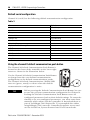
Make Sure that You Have All the Components
These components ship with the controller:
Table 1
Component:
Description:
1769-BA battery
IMPORTANT
The 1769-BA battery is the only battery you can use with the
CompactLogix controller.
1747-KY controller key
You may also use these components with the controller:
Table 2
If you want to:
Then use this component:
add nonvolatile memory
1784-CF64 Industrial CompactFlash card
11
connect a device to the
RS-232 port
1756-CP3 or 1747-CP3 serial cable
18
connect to the ControlNet
network
Either:
• ControlNet taps for connections from
controller channels A or B to the
ControlNet network
or
• 1786-CP cable for connections from a
programming terminal to the
ControlNet network via the
controller’s Network Access
Port (NAP)
Publication 1769-IN070B-EN-P - December 2004
For more information,
see page:
22
23
1769-L32C, -L35CR CompactLogix Controllers
7
Plan the System
Consider the following when planning your CompactLogix system:
• The CompactLogix controller is always the left-most module in the system.
• The CompactLogix controller must be located within four modules of the
power supply.
• Some I/O module’s may be located up to 8 modules away from the power
supply. See the documentation for your 1769 I/O modules for details.
• The 1769-L32C controller supports as many as 16 I/O modules in a
maximum of 3 I/O banks with 2 expansion cables.
• The 1769-L35CR controller supports as many as 30 I/O modules in a
maximum of 3 I/O banks with 2 expansion cables.
• Each I/O bank requires its own power supply.
• Only one controller can be used in a CompactLogix system.
• A 1769-ECR (right end cap) or 1769-ECL (left end cap) is required to
terminate the end of the communication bus.
ATTENTION
This controller has a Network Access Port (NAP) for temporary
connections to the ControlNet network. Do not plug a DH-485
network cable or an RJ-45 connector for EtherNet/IP into the NAP.
Undesirable behavior and/or damage to the port may result.
Publication 1769-IN070B-EN-P - December 2004
8
1769-L32C, -L35CR CompactLogix Controllers
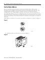
Set the Node Address
Every ControlNet network requires at least one module that is able to store
parameters and configure the network with those parameters upon start-up. The
CompactLogix controller is called a ‘keeper’ because it keeps the network
configuration. The CompactLogix controller can keep the network parameters at
any legal node address (01 to 99). Multiple devices on any one network can act as
the network keepers. Each device capable of being the network keeper acts to back
up the current keeper. This backup function is automatic and requires no action on
your part.
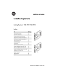
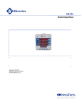
Node address switches are set to the 99 position at shipment, as shown in Figure 1.
Figure 1
43868
1. Slide the side cover forward, as shown in Figure 2.
Figure 2
43860
Publication 1769-IN070B-EN-P - December 2004
1769-L32C, -L35CR CompactLogix Controllers
9
2. Set the node address via the controller switches and a small screwdriver, as
shown in Figure 3.
6 7
01 2
34
5
Figure 3
6 7
01 2
5
89
34
89
31504-M
After setting the node address switches, write the node address on the front
panel overlay.
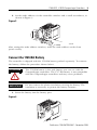
Connect the 1769-BA Battery
The controller is shipped with the 1769-BA battery packed separately. To connect
the battery, follow the procedure shown below.
ATTENTION
The 1769-BA battery is the only battery you can use with the
CompactLogix controllers. The 1747-BA battery is not compatible
with the CompactLogix controllers and may cause problems.
IMPORTANT
Do not remove the plastic insulation covering the battery. The
insulation is necessary to protect the battery contacts.
1. Insert the battery into the battery port.
Figure 4
31499-M
Publication 1769-IN070B-EN-P - December 2004
10
1769-L32C, -L35CR CompactLogix Controllers
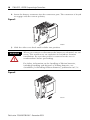
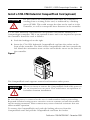
2. Insert the battery connector into the connector port. The connector is keyed
to engage with the correct polarity.
Figure 5
31500-M
3. Slide the side cover back until it clicks into position.
WARNING
When you connect or disconnect the battery an electrical arc can
occur. This could cause an explosion in hazardous location
installations. Be sure that power is removed or the area is
nonhazardous before proceeding.
For Safety information on the handling of lithium batteries,
including handling and disposal of leaking batteries, see
Guidelines for Handling Lithium Batteries, publication AG 5-4.
Figure 6
31501-M
Publication 1769-IN070B-EN-P - December 2004
1769-L32C, -L35CR CompactLogix Controllers
11
Install a 1784-CF64 Industrial CompactFlash Card (optional)
ATTENTION
Do not remove the CompactFlash card while the controller is
reading from or writing to the card, as indicated by a flashing
green CF LED. This could corrupt the data on the card or in the
controller, as well as corrupt the latest firmware in the controller.
A 1784-CF64 Industrial CompactFlash card provides nonvolatile memory for a
CompactLogix controller. This is an optional feature and is not required to operate
the controller. Install the card as follows:
1. Push the locking tab to the right.
2. Insert the 1784-CF64 Industrial CompactFlash card into the socket on the
front of the controller. The label of the CompactFlash card faces towards the
left. Match the orientation arrow on the card with the arrow on the front of
the controller.
Figure 7
The CompactFlash card supports removal and insertion under power.
WARNING
When you insert or remove the CompactFlash Card while power is
on, an electrical arc can occur. This could cause an explosion in
hazardous location installations.
Be sure that power is removed or the area is nonhazardous before proceeding.
Repeated electrical arcing causes excessive wear to contacts on both the module
and its mating connector. Worn contacts may create electrical resistance that can
affect module operation.
To remove the CompactFlash card, push the locking tab away from the
CompactFlash card and pull the CompactFlash card from the socket.
Publication 1769-IN070B-EN-P - December 2004
12
1769-L32C, -L35CR CompactLogix Controllers
Assemble the System
The controller can be attached to an adjacent I/O module or power supply before
or after mounting. For mounting instructions, see Panel mounting on page 17 or
DIN rail mounting on page 17.
WARNING
The CompactLogix controller is not designed for removal and
insertion under power. If you connect or disconnect the
communications cable while power is applied to this module or
the wiring while the field-side power is on, an electrical arc can
occur. This could cause an explosion in hazardous location
installations.
Be sure that power is removed or the area is nonhazardous before
proceeding.
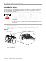
1. Disconnect line power.
2. Make sure the lever of the adjacent module is in the unlocked (fully
right) position.
Figure 8
Adjacent module
Unlocked position
3. Use the upper and lower tongue-and-groove slots to secure the
modules together.
Publication 1769-IN070B-EN-P - December 2004
1769-L32C, -L35CR CompactLogix Controllers
13
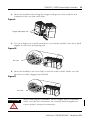
4. Move the module back along the tongue-and-groove slots until the bus
connectors line up with each other.
Figure 9
Tongue-and-groove slots
5. Use your fingers or a small screwdriver to push the module’s bus lever back
slightly to clear the positioning tab.
Figure 10
Bus lever
6. Move the module’s bus lever fully to the left until it clicks. Make sure the
Bus Lever is fully engaged and locked.
Figure 11
Bus lever
ATTENTION
When attaching the controller, power supply and I/O modules,
make sure the bus connectors are securely locked together to
ensure proper electrical connection.
Publication 1769-IN070B-EN-P - December 2004
14
1769-L32C, -L35CR CompactLogix Controllers
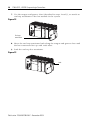
7. Use the tongue-and-groove slots (described in steps 2 and 3), to attach an
end cap terminator to the last module in the system.
Figure 12
End cap
terminator
8. Move the end cap terminator back along the tongue-and-groove slots until
the bus connectors line up with each other.
9. Lock the end cap bus terminator.
Figure 13
Lock
Publication 1769-IN070B-EN-P - December 2004
1769-L32C, -L35CR CompactLogix Controllers
15
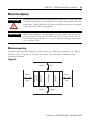
Mount the System
ATTENTION
During panel or DIN rail mounting of all devices, be sure that all
debris (metal chips, wire strands, etc.) is kept from falling into the
controller. Debris that falls into the controller could cause damage
while the controller is energized.
IMPORTANT
When mounting the CompactLogix system, either use screws to
panel mount system OR use DIN rail. Do NOT use both. Use of
both mounting methods may cause hardware damage and cause
the system to fail.
Minimum spacing
Maintain spacing from enclosure walls, wireways, adjacent equipment, etc. Allow
50 mm (2 in.) of space on all sides, as shown. This provides ventilation and
electrical isolation.
Figure 14
Top
50 mm
End Cap
50 mm
Compact I/O
Power Supply
Side
Compact I/O
50 mm
CompactLogix
Controller
50 mm
Side
Bottom
Publication 1769-IN070B-EN-P - December 2004
16
1769-L32C, -L35CR CompactLogix Controllers
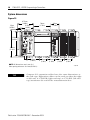
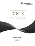
System dimensions
Figure 15
67.5mm
(2.68in)
15mm
(0.59in)
52.5mm
(2.06in)
70mm
(2.76in)
35mm
(1.38in)
118mm
(4.65in)
132mm
(5.20in)
52.5mm
(2.06in)
35mm
(1.38in)
NOTE: All dimensions are in mm (in.).
Hole spacing tolerance: ±0.4 mm (0.016 in.)
TIP
35mm
(1.38in)
35mm
(1.38in)
35mm
(1.38in)
31502-M
Compact I/O expansion cables have the same dimensions as
the end caps. Expansion cables can be used on either the right
or left end. A 1769-ECR (right end cap) or 1769-ECL (left end
cap) terminates the end of the communication bus.
Publication 1769-IN070B-EN-P - December 2004
1769-L32C, -L35CR CompactLogix Controllers
17
Panel mounting
Mount the controller to a panel using two screws per module. Use M4 or #8
panhead screws. Mounting screws are required on every module.
The following procedure allows you to use the assembled modules as a template
for drilling holes in the panel. Due to module mounting hole tolerance, it is
important to follow these procedures:
1. On a clean work surface, assemble no more than three modules.
2. Using the assembled modules as a template, carefully mark the center of all
module-mounting holes on the panel.
3. Return the assembled modules to the clean work surface, including any
previously mounted modules.
4. Drill and tap the mounting holes for the recommended M4 or #8 screw.
5. Place the modules back on the panel and check for proper hole alignment.
6. Attach the modules to the panel using the mounting screws.
TIP
If mounting more modules, mount only the last one of this
group and put the others aside. This reduces remounting
time during drilling and tapping of the next group.
7. Repeat steps 1 to 6 for any remaining modules.
DIN rail mounting
The controller can be mounted using the following DIN rails:
• 35 x 7.5 mm (EN 50 022 - 35 x 7.5)
• 35 x 15 mm (EN 50 022 - 35 x 15)
Before mounting the controller on a DIN rail, close the DIN rail latches. Press the
DIN rail mounting area of the controller against the DIN rail. The latches will
momentarily open and lock into place.
Publication 1769-IN070B-EN-P - December 2004
18
1769-L32C, -L35CR CompactLogix Controllers
Grounding considerations
This product is intended to be mounted to a well-grounded mounting surface such
as a metal panel. Additional grounding connections from the controller’s mounting
tabs or DIN rail (if used), are not required unless the mounting surface cannot be
grounded. Refer to Industrial Automation Wiring and Grounding Guidelines,
Allen-Bradley publication 1770-4.1, for additional information.
ATTENTION
This Product is grounded through the DIN rail to chassis ground.
Use zinc plated yellow-chromate steel DIN rail to assure proper
grounding. The use of other DIN rail materials (e.g. aluminum,
plastic, etc.) that can corrode, oxidize, or are poor conductors,
can result in improper or intermittent grounding.
Connect a Programming Terminal to the Controller Via
RS-232 Connections
Use an RS-232 cable to connect your CompactLogix controller to your programming
terminal. You can use either of the following RS-232 cables:
• 1747-CP3
or
• 1756-CP3
WARNING
If you connect or disconnect the serial cable with power applied
to this module or the serial device on the other end of the cable,
an electrical arc can occur. This could cause an explosion in
hazardous location installations.
Be sure that power is removed or the area is nonhazardous
before proceeding.
Publication 1769-IN070B-EN-P - December 2004
1769-L32C, -L35CR CompactLogix Controllers
19
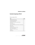
Figure 16 shows the RS-232 cable connections.
Figure 16
9-pin, female D-shell
right-angle cable end
9-pin, male D-shell straight
cable end
1747-CP3 or 1756-CP3
1 CD
1 CD
2 RDX
2 RDX
3 TXD
3 TXD
4 DTR
4 DTR
COMMON
COMMON
6 DSR
6 DSR
7 RTS
7 RTS
8 CTS
8 CTS
9
This cable must be shielded and tied to the
connector housing.
straight cable end
9
right-angle cable end
1. Connect the 9-pin, right-angle connector of the RS-232 cable to the serial
port on your CompactLogix controller.
Figure 17
2. Connect the 9-pin, straight connector of the RS-232 cable to your
programming terminal.
Figure 18
Publication 1769-IN070B-EN-P - December 2004
20
1769-L32C, -L35CR CompactLogix Controllers
Default serial configuration
Channel 0 (serial) has the following default communication configuration.
Table 3
Parameter
Default
Protocol
DF1 full-duplex
Baud Rate
19.2 Kbit/s
Parity
none
Station Address
0
Control Lines
no handshaking
Error Detection
BCC
Embedded Responses
auto detect
Duplicate Packet (Message) Detect
enabled
ACK Timeout
50 (x 20 ms)
NAK Receive Limit
3 retries
ENQ Transmit Limit
3 retries
Data Bits
8
Stop Bits
1
Using the channel 0 default communication push button
The Channel 0 Default Communication Push Button is
located on the front of the controller in the lower right
corner as shown in the illustration below.
Use the Channel 0 Default Communication Push Button
to change from the user-defined communication
configuration to the default communications mode.
The Channel 0 Default Communications (DCH0) LED
turns on (green, steady) to show when the default
communication configuration is active.
TIP
Before pressing the Default Communication Push Button, be sure
to note the present communication configuration for Channel 0.
Pushing the Default Communication Push Button resets all
configured parameters back to their default settings. To return the
channel to its user-configured parameters, you must enter them
manually while online with the controller or download them as
part of an RSLogix 5000 Project file. To accomplish this online
using RSLogix 5000, enter the Controller Properties screen and
use the Serial Port, System Protocol and User Protocol tabs.
Publication 1769-IN070B-EN-P - December 2004
1769-L32C, -L35CR CompactLogix Controllers
21
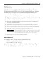
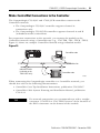
Make ControlNet Connections to the Controller
The CompactLogix 1769-L32C and 1769-L35CR controllers connect to the
ControlNet network.
• The CompactLogix 1769-L32C controller supports channel A
connections only.
• The CompactLogix 1769-L35CR controller supports channels A and B
(redundant media) connections.
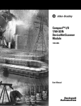
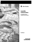
For permanent connections to the network, you connect the module to the
ControlNet network using a ControlNet tap (e.g., 1786-TPR, -TPS, -TPYR, -TPYS).
Figure 19 shows an example ControlNet network using redundant media.
Figure 19
ControlNet node
ControlNet link
redundant media
(available on the
1769-L35CR only)
ControlNet node
43893
When connecting the CompactLogix controller to a ControlNet network, you
should also refer to the following documentation:
• ControlNet Coax Tap Installation Instructions, publication 1786-IN007
• ControlNet Cable System Planning and Installation Manual, publication
1786-6.2.1
TIP
For network connections we recommend taps with a straight
connector (1786-TPS or 1786-TPYS) because of the location of
the BNC connectors on the bottom of the module.
Publication 1769-IN070B-EN-P - December 2004
22
1769-L32C, -L35CR CompactLogix Controllers
Connect the Controller to the Network Via a ControlNet Tap
Typically, ControlNet taps are used to make permanent connections from the
CompactLogix controller to the network. Perform the following steps to connect the
module to the network using a ControlNet tap.
1. Remove and save the dust cap(s) from the ControlNet tap(s).
ATTENTION
Do not allow any metal portions of the tap to contact any
conductive material. If you disconnect the tap from the module,
place the dust cap back on the straight or right angle connector to
prevent the connector from accidentally contacting a metallic
grounded surface.
Figure 20
Segment 1
Segment 2
Dust caps
2. Connect the tap’s straight or right-angle connector to the module’s BNC
connector as shown in Figure 21 on page 23.
WARNING
IMPORTANT
If you connect or disconnect the communications cable with power
applied to this module or any device on the network, an electrical
arc can occur. This could cause an explosion in hazardous location
installations.
To prevent inadvertent reversal of the tap connections (resulting
in incorrect status displays requiring troubleshooting), check the
tap drop cable for the label indicating the attached segment
before making your connection.
Publication 1769-IN070B-EN-P - December 2004
1769-L32C, -L35CR CompactLogix Controllers
23
Figure 21
Tap connected to a CompactLogix
controller not using redundant media
Taps connected to a CompactLogix controller
using redundant media (1769-L35CR only)
Segment 1
Segment 2
Tap
A
A
B
43861
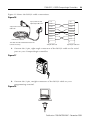
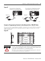
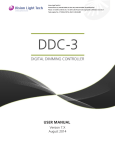
Connect a Programming Terminal to the Network Via a 1786-CP Cable
You can use the CompactLogix controller’s network access port (NAP) to connect a
programming terminal to the ControlNet network. Figure 22 shows the 1786-CP
cable connections.
Figure 22
8
shield
shield
GND REF
GND REF
+24V DC
+24V DC
7
6 PTRx_H
3.05m
(10')
5
PTRx_L
PTTx_L
PTTx_L
PTRx_L
4
3 PTTx_H
2
1
PTTx_H
PTRx_H
+24V DC
+24V DC
GND REF
GND REF
1
2
3
4
5
6
7
8
This cable is not a straight through cable.
ATTENTION
Use the 1786-CP cable when you connect a programming terminal
to the network through the NAP; using another cable could result
in possible network failures or product damage.
The NAP is for temporary local programming purposes only and
not intended for permanent connection.
Publication 1769-IN070B-EN-P - December 2004
24
1769-L32C, -L35CR CompactLogix Controllers
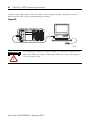
Connect one end of the 1786-CP cable to the CompactLogix controller and the
other end to NAP of the programming terminal.
Figure 23
31503-M
ATTENTION
Do not plug a DH-485 network cable or an RJ-45 connector for
EtherNet/IP to the NAP. Undesirable behavior and/or damage to
the port may result.
Publication 1769-IN070B-EN-P - December 2004
1769-L32C, -L35CR CompactLogix Controllers
25
Install the Appropriate Electronic Data Sheet (EDS) Files
If you have RSLinx software, version 2.43 or greater, the most current EDS files
were installed with the software. If you are using RSLinx software, version 2.42 or
earlier, you might need to install EDS files. You need EDS files for:
•
•
•
•
•
•
1769-L32C controller
1769-L32C ControlNet port
1769-L35CR controller
1769-L35CR ControlNet port
1769 CompactBus
1769 local adapter
All of these EDS files, except for the 1769 CompactBus file, are updated for each
firmware revision. There is also a revision 1.x of the EDS files that you need for
new controllers. Each controller ships with revision 1.x firmware. In order to
update the firmware, you must have these revision 1.x EDS files installed:
• 0001000E00500100.eds for the controller
• 0001000C00A00100.eds for the ControlNet port
The EDS files are available on the CD for RSLogix 5000 Enterprise Series software,
version 13. The files are also available at:
http://www.ab.com/networks/eds.
Load the Controller Firmware
The controller ships without working firmware. You must download the current
firmware before you can use the controller. To load firmware, you can use:
• ControlFlash utility that ships with RSLogix 5000
• AutoFlash that starts through RSLogix 5000 when you try to download a
project and the controller does not have the current firmware.
• 1784-CF64 CompactFlash card with valid memory already loaded
Publication 1769-IN070B-EN-P - December 2004
26
1769-L32C, -L35CR CompactLogix Controllers
The firmware is available with RSLogix 5000 or you can download it from the
support website:
1. Go to http://support.rockwellautomation.com
2. In the left column (frame), select Firmware Updates under Technical Support
3. Select the firmware revision.
The download process will require you to enter the serial number of your
RSLogix 5000 programming software.
If you load (flash) controller firmware via the ControlFlash or AutoFlash utilities,
you need either a serial or ControlNet connection to the controller. Flashing via a
ControlNet connection is faster than the serial connection.
Using ControlFlash to load firmware
You can use ControlFlash to load firmware through either a ControlNet connection
or a serial connection.
1. Make sure the appropriate network connection is made before starting.
2. Start the ControlFlash utility. Click Next when the Welcome screen appears.
3. Select the catalog number of the controller and click Next.
4. Expand the network until you see the controller. If the required network is
not shown, first configure a driver for the network in RSLinx software.
5. Select the controller and click OK
6. Select the revision level to which you want to update the controller and click
Next.
7. To start the update of the controller, click Finish and then click Yes.
8. After the controller is updated, the status box displays Update complete.
Click OK.
9. To close ControlFlash software, click Cancel and then click Yes.
Publication 1769-IN070B-EN-P - December 2004
1769-L32C, -L35CR CompactLogix Controllers
27
Using AutoFlash to load firmware
You can use AutoFlash to load firmware through either a ControlNet connection or
a serial connection.
1. Make sure the appropriate network connection is made before starting.
2. Use RSLogix 5000 programming software to attempt to download to a
controller project. This automatically launches AutoFlash.
3. Select the catalog number of the controller and click Next.
4. Expand the network until you see the controller. If the required network is
not shown, first configure a driver for the network in RSLinx software.
5. Select the controller and click OK
6. Select the revision level to which you want to update the controller and click
Next.
7. To start the update of the controller, click Finish and then click Yes.
8. After the controller is updated, the status box displays Update complete.
Click OK.
9. To close AutoFlash software, click Cancel and then click Yes.
Using a CompactFlash card to load firmware
If you have an existing controller that is already configured and has firmware
loaded, you can store the current controller user program and firmware on
CompactFlash and use that card to update other controllers.
1. Use RSLogix 5000 software to store the controller user program and
firmware of a currently configured controller to the CompactFlash card.
Access the Nonvolatile Memory tab of the Controller Properties dialog. Make
sure to select Load Image On Powerup when you save to the card.
2. Remove the card and insert it into a controller that you want to have the
same firmware and controller user program.
3. When you power up the second controller, the image stored on the
CompactFlash card is loaded into the controller.
Publication 1769-IN070B-EN-P - December 2004
28
1769-L32C, -L35CR CompactLogix Controllers
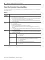
Select the Controller’s Operating Mode
Use the keyswitch on the front panel of the controller to determine the controller’s
operating mode.
Table 4
Keyswitch
Position
Description
RUN
• Upload projects.
• Run the program and enable outputs.
• You cannot create or delete tasks, programs, or routines. You cannot create or delete
tags or edit online while the keyswitch is in the RUN position.
• You cannot change the mode using the programming software while the keyswitch is
in the RUN position.
PROG
•
•
•
•
Disable outputs.
Upload/download projects.
Create, modify, and delete tasks, programs, or routines.
The controller does not execute (scan) tasks while the keyswitch is in the PROG
position.
• You cannot change the mode through the programming software while the keyswitch
is in the PROG position.
REM
• Upload/download projects.
• Change between Remote Program, Remote Test, and Remote Run modes through the
programming software.
Remote Run
• The controller executes (scans) tasks.
• Enable outputs.
• Edit online.
Remote Program
•
•
•
•
•
Remote Test
• Execute tasks with outputs disabled.
• Edit online.
Disable outputs.
Create, modify, and delete tasks, programs or routines.
Download projects.
Edit online.
The controller does not execute (scan) tasks.
Publication 1769-IN070B-EN-P - December 2004
1769-L32C, -L35CR CompactLogix Controllers
29
Verify Proper Controller Operation
To verify that your controller is operating properly, use the controller’s various
status indicators as described in the following pages.
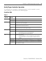
Controller LEDs
Table 5
If this
indicator:
has this
display:
It means:
RUN
off
The controller is in Program or Test mode.
steady green
The controller is in Run mode.
off
No tags contain I/O force values.
I/O forces are inactive (disabled).
steady amber
I/O forces are active (enabled).
I/O force values may or may not exist.
flashing
amber
One or more input or output addresses have been forced to an On or Off
state, but the forces have not been enabled.
off
The battery supports memory.
steady red
Either the battery is:
• not installed. In this case, install the battery.
• 95% discharged and should be replaced.
off
Either of the following:
• There are no devices in the I/O configuration of the controller.
• The controller does not contain a project (controller memory is
empty).
steady green
The controller is communicating with all the devices in its I/O configuration.
flashing green
One or more devices in the controller’s I/O configuration are not responding.
flashing red
The controller is not communicating to any devices.
The controller is faulted.
FORCE
BAT
I/O
Publication 1769-IN070B-EN-P - December 2004
30
1769-L32C, -L35CR CompactLogix Controllers
Table 5
If this
indicator:
has this
display:
It means:
OK
off
No power is applied.
flashing red
If the controller is:
a new controller
Then:
the controller requires a firmware update
not a new controller
A major fault occurred. To clear the fault, either:
- Turn the keyswitch from PROG to RUN to PROG
- Go online with RSLogix 5000
steady red
Controller detected a non-recoverable fault and cleared the project. To
recover:
1. Cycle power to the chassis.
2. Download the project.
3. Change to Run mode.
If the OK LED remains solid red, contact your Rockwell Automation
representative or local distributor.
steady green
Controller is OK.
flashing green
The controller is storing or loading a project to or from nonvolatile memory.
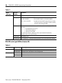
RS-232 serial port LEDs (channel 0)
Table 6
Indicator:
Color:
DCH0
off
Channel 0 is configured differently than the default serial configuration.
steady green
Channel 0 has the default serial configuration.
off
No RS-232 activity.
flashing green
RS-232 activity.
CH0
Description:
Publication 1769-IN070B-EN-P - December 2004
1769-L32C, -L35CR CompactLogix Controllers
31
CompactFlash card LED
Do not remove the CompactFlash card while the controller is
reading from or writing to the card, as indicated by a flashing
green CF LED. This could corrupt the data on the card or in the
controller, as well as corrupt the latest firmware in the controller.
ATTENTION
Table 7
Indicator:
Color:
Description:
CF
off
No activity.
flashing green
The controller is reading from or writing to the CompactFlash card.
flashing red
CompactFlash card does not have a valid file system.
Interpret Status Indicators as Related to the ControlNet Network
Use the following status indicators to determine how your CompactLogix controller
is operating on the ControlNet network:
• Module Status
• Network Status
These status indicators provide information about the controller and the network
when the controller is connected to ControlNet via the BNC connectors. describes
the possible conditions for module and network status indicators.
Table 8
If an indicator is described
in this condition:
It means:
steady
The indicator is on continuously in the defined state.
alternating
Two indicators alternate between the two defined states at the same time
(applies to both indicators when viewed together); the two indicators are
always in opposite states, out of phase.
flashing
The indicator alternates between the two defined states (applies to each
indicator viewed independent of the other); if both indicators are flashing,
they flash together, in phase.
Publication 1769-IN070B-EN-P - December 2004
32
1769-L32C, -L35CR CompactLogix Controllers
IMPORTANT
Keep in mind that the Module Status indictor reflects the module state
(e.g., self-test, firmware update, normal operation but no connection
established). The network status indicators, A and B, reflect network
status. Remember that the host is able to engage in local messaging with
the card although it is detached from the network. Therefore, the Module
Status LED is flashing green if the host has successfully started the card.
Note, however, that until the host removes reset, all LEDs on the
daughtercard will remain off.
When you view the indicators, always view the Module Status indicator
first to determine the state of the daughtercard. This information may help
you to interpret the network status indicators. As a general practice, view
all status indicators (Module Status and Network Status) together to gain a
full understanding of the daughtercard’s status.
Module Status (MS) indicator
Table 9
If the Module
Status (MS)
indicator is:
off
It means:
Take this action:
the controller has no power.
Apply power.
the controller is faulted.
Make sure that the controller is firmly seated
in the slot.
steady red
a major fault has occurred on the
controller.
flashing red
a minor fault has occurred because a
firmware update is in progress.
No action required (firmware update in
progress.)
a node address switch change occurred.
The controller’s node address switches
may have been changed since power-up.
Change the node address switches back to
the original setting. The module will continue
to operate properly.
the controller uses invalid firmware.
Update the controller firmware with the
ControlFlash Update utility.
the controller’s node address duplicates
that of another device.
steady green
connections are established.
flashing green
no connections are established.
flashing red/green the controller is performing
self-diagnostics.
Publication 1769-IN070B-EN-P - December 2004
1. Cycle power.
2. If the problem persists, replace the
controller.
1. Remove power.
2. Change the node address to a
unique setting.
3. Reapply power.
None
Establish connections, if necessary.
Wait briefly to see if problem corrects itself
If problem persists, check the host. If the
daughtercard cannot communicate with the
host, the card may remain in self-test mode.
1769-L32C, -L35CR CompactLogix Controllers
33
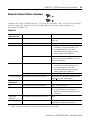
Network Channel Status indicators
Channel B is only labelled on the 1769-L35CR controller. The 1769-L32C controller
only has channel A but uses the second indicator in some LED patterns as
described in Table 10.
Table 10
If both channel
indicators are:
It means:
Take this action:
off
a channel is disabled.
Program network for redundant media, if
necessary.
steady green
normal operation is occurring.
None
flashing green/off
temporary network errors have occurred.
the node is not configured to go online.
1. Check media for broken cables, loose
connectors, missing terminators, etc.
2. If condition persists, refer to the
ControlNet Planning and Installation
Manual, publication 1786-6.2.1.
Make sure the network keeper is present and
working and the selected address is less or
equal to the UMAX(1).
flashing red/off
media fault has occurred.
1. Check media for broken cables, loose
connectors, missing terminators, etc.
2. If condition persists, refer to the
ControlNet Planning and Installation
Manual, publication 1786-6.2.1.
no other nodes present on the network.
Add other nodes to the network.
flashing red/green the network is configured incorrectly.
Reconfigure the ControlNet network so that
UMAX > the card’s node address.
If either channel
indicator is:
It means:
Take this action:
off
you should check the MS indicators.
Check the MS indicators.
steady red
the controller is faulted.
alternating
red/green
the controller is performing a self-test.
alternating red/off the node is configured incorrectly.
(1)
1. Cycle power.
2. If the fault persists, contact your
Rockwell Automation representative or
distributor.
None
Check the card’s network address and other
ControlNet configuration parameters.
UMAX is the highest node address on a ControlNet network that can transmit data.
Publication 1769-IN070B-EN-P - December 2004
34
1769-L32C, -L35CR CompactLogix Controllers
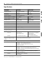
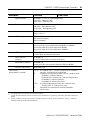
Specifications
Description
1769-L32C
1769-L35CR
Communication Ports
RS-232, NAP, ControlNet
channel A
RS-232, NAP, ControlNet channels
A and B
User Memory
750 Kbytes
1.5 Mbytes
Nonvolatile Memory
1784-CF64 CompactFlash
Maximum Number of I/O Modules
16 I/O modules
30 I/O modules
Maximum Number of I/O Banks
3 banks
3 banks
Backplane Current(1)
650 mA at 5V dc
40 mA at 24V dc
680 mA at 5V dc
40 mA at 24V dc
Power Dissipation
4.21W
4.36W
Power Supply Distance Rating
4 (The controller must be within four slot positions of the power supply.)
Replacement Battery
1769-BA
Weight
0.32 kg (0.70 lb.)
Programming Cable
1747-CP3 or 1756-CP3
Panel Mounting Screw Torque
(using M4 or #8 screws)
10 - 16 in-lb (1.1 - 1.8 Nm)
Wiring
Connectors
1 BNC connector
1 NAP (1786-CP cable)
2 BNC connectors for redundant
media operation
1 NAP (1786-CP cable)
Category
2 – On communication ports(3)
2 – On communication ports(3)
Isolation Voltage
(continuous-voltage withstand
rating)
30V dc
Tested to withstand 710V dc for 60 seconds
Environmental Conditions
Operational Temperature
IEC 60068-2-1 (Test Ad, Operating Cold),
IEC 60068-2-2 (Test Bd, Operating Dry Heat),
IEC 60068-2-14 (Test Nb, Operating Thermal Shock):
0 to 60°C (32 to 140°F)
Storage Temperature
IEC 60068-2-1 (Test Ab, Un-packaged Non-operating Cold),
IEC 60068-2-2 (Test Bb, Un-packaged Non-operating Dry Heat),
IEC 60068-2-14 (Test Na, Un-packaged Non-operating Thermal Shock):
-40 to 85°C (-40 to 185°F)
Relative Humidity
IEC 60068-2-30 (Test Db, Un-packaged Non-operating Damp Heat):
5 to 95% non-condensing
Vibration
IEC 60068-2-6 (Test Fc, Operating):
5g @ 10-500Hz
Publication 1769-IN070B-EN-P - December 2004
1769-L32C, -L35CR CompactLogix Controllers
Description
(2)
(3)
1769-L35CR
Operating Shock
IEC 60068-2-27 (Test Ea, Unpackaged Shock):
DIN mount - Operating: 20G
Panel mount - Operating: 30G
Non-Operating Shock
IEC 60068-2-27 (Test Ea, Unpackaged Shock):
DIN mount - Non-operating: 30G
Panel mount - Non-operating: 40G
Emissions
CISPR 11:
Group 1, Class A
ESD Immunity
IEC 61000-4-2:
4kV contact discharges
8kV air discharges
Radiated RF Immunity
IEC 61000-4-3:
10V/m with 1kHz sine-wave 80%AM from 80MHz to 2000MHz
10V/m with 200Hz 50% Pulse 100%AM at 900Mhz
10V/m with 200Hz 50% Pulse 100%AM at 1890Mhz
EFT/B Immunity
IEC 61000-4-4:
+/-2kV at 5kHz on communications ports
Surge Transient
Immunity
IEC 61000-4-5:
+/-2kV line-earth(CM) on communications ports
Conducted RF Immunity
IEC 61000-4-6:
10Vrms with 1kHz sine-wave 80%AM from 150kHz to 80MHz
Enclosure Type Rating
None (open-style)
Certifications:(2)
(when product is marked)
(1)
1769-L32C
35
c-UL-us UL Listed for Class I, Division 2 Group A,B,C,D Hazardous
Locations, certified for U.S. and Canada
CE
European Union 89/336/EEC EMC Directive, compliant with:
EN 50082-2; Industrial Immunity
EN 61326; Meas./Control/Lab., Industrial Requirements
EN 61000-6-2; Industrial Immunity
EN 61000-6-4; Industrial Emissions
C-Tick Australian Radiocommunications Act, compliant with:
AS/NZS CISPR 11; Industrial Emissions
CI
ControlNet Int'l conformance tested to ControlNet
specifications
This specification is also known as Power Consumption.
See the Product Certification link at www.ab.com for Declarations of Conformity, Certificates, and other certification
details.
Use this Conductor Category information for planning conductor routing. Refer to Publication 1770-4.1, "Industrial
Automation Wiring and Grounding Guidelines".
Publication 1769-IN070B-EN-P - December 2004
Obtain Related Documentation
This product also uses the following manuals:
• CompactLogix System User Manual, publication 1769-UM0011
• ControlNet Modules in Logix5000 Control Systems User Manual,
publication CNET-UM001
• Logix5000 Controllers Common Procedures, publication 1756-PM001
• Logix5000 Controllers General Instructions Reference Manual, publication
1756-RM003
• Logix5000 Controllers Process Control and Drives Instructions Reference
Manual, publication 1756-RM006
To view manuals, visit www.rockwellautomation.com/literature. To obtain a hard
manual, contact your distributor or Rockwell Automation representative.
ö
Publication 1769-IN070B-EN-P - December 2004
Supersedes Publication 1769-IN070A-EN-P - September 2004
PN 957944-01
Copyright © 2004 Rockwell Automation, Inc. All rights reserved. Printed in the U.S.A.