1
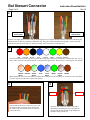
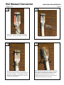
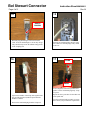
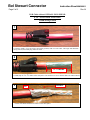
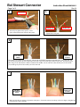
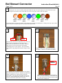
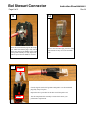
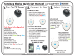
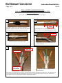
Bel Stewart Connector
Instruction Sheet MN390011
Page 1 of 8
Rev A1
PLUG ASSEMBLY INSTRUCTIONS FOR
Cable with INDIVIDUALLY SHIELDED PAIRS (PIMF or SFTP)
T568B Wiring Pattern
For Cable with Overall Foil Shield (FTP), See Page 9
1
2
1 to 1 ¼
INCHES
Cut cable to length. If you are using a strain relief
grommet, slide it over the cable. The larger ends should
be facing outward, toward the plug end of the cable.
Cut and strip off 1 to 11/4 inches of the outer jacket.
Be careful not to cut or nick the braid and foil shields.
3
4
¼ INCH
Pull the braid back over the cable jacket.
Spread out the 4 wire pairs and trim foil to ¼
inch on all 4 pairs.
5
BROWN PAIR
ORANGE PAIR
TAPERED END
OF PLASTIC
WIRE ALIGNER
OTHER END OF CABLE SHOWING GREEN
PAIR IN FRONT
Place plastic wire aligner between the pairs. The tapered end should be toward the braid and jacket. The orange pair will
go to the deep channel on the left side and the brown pair will go toward the deep channel on the right. The blue and
green pairs will go to the sides that have shallow channels at the middle.
Bel Stewart Connector
Instruction Sheet MN390011
Page 2 of 8
Rev A1
6
END WITH BLUE
PAIR IN FRONT
END WITH GREEN
PAIR IN FRONT
Push the wire aligner down as far as it will go and push pairs into wire aligner channels. Flatten out the wires and arrange the
insulation colors so that they match the T568B color map. Keep the red on left and the brown on right. On one end of the
cable the blue pair will be towards you, and the green pair will be towards you on the other end.
7
RED
ORANGE
BLACK
BLUE
WHITE
GREEN
YELLOW
BROWN
The color pattern shown in these pictures represent the wiring colors used by one manufacturer. Wiring colors may vary by
cable.
Please verify the color pattern specific to your particular requirements. Shown below is a more typical color scheme.
.
ORANGE
/WHITE
ORANGE
GREEN
/WHITE
BLUE
BLUE
/WHITE
GREEN
BROWN
/WHITE
BROWN
When aligning the wires to the color pattern, maintain the existing twist of the wire pairs. Do not add or remove more than
½ twist to any pair to achieve the required color pattern.
8
9
SLOTS
Trim the ends of the wires to make them even. This
will make it easier to insert the wires into the load
bar. Remove the least amount of wire necessary to
even out the wires.
WEDGE
Insert the ends of the wires into the wide end of
the load bar, maintaining the wire color sequence.
The side with the slots and the wedge shaped end
should be facing towards you
Bel Stewart Connector
Instruction Sheet MN390011
Page 3 of 8
10
Rev A1
11
Bring the loadbar down, tight against the plastic
wire aligner. Trim the wires flush to the loadbar.
12
Wrap the braid over the jacket. Press the foil
covered pairs fully into the slots in the channels of
the plastic wire aligner. Ensure that the foil does
not stick out as this makes it difficult to insert this
assembly into the plug body.
Dress the braid to one side of the jacket.
13
Keep the orange pair to the left and the brown to the
right. Push the assembled wires, loadbar, and plastic
wire aligner into the plug body subassembly. The
plug latch tab should be facing away from you.
Firmly push the plug until the wires come in contact
with the front inside surface of the plug.
Bel Stewart Connector
Instruction Sheet MN390011
Page 4 of 8
Rev A1
14
15
SHIELD
FINGERS
Bend the plug shield fingers inward toward the
cable. Press the shield fingers as far as they will go.
They should easily fit into the Shield Crimp portion
of the crimping tool.
16
Insert the un-terminated plug into the crimp
tool. Make sure that the plug is fully seated
in the tool.
17
PUSH
PUSH
If used, align the strain relief grommet and
push it over the terminated plug body. Snap
it in place.
Squeeze the handles of the crimp tool together until
they are fully depressed, and will open when the
handle is released.
Remove the terminated plug from the crimp tool.
Repeat the above procedure for the other end
of the patch cord.
Test the completed cable assembly to ensure
that it meets your performance requirements.
Bel Stewart Connector
Instruction Sheet MN390011
Page 5 of 8
Rev A1
FOR Cable with an OVERALL FOIL SHIELD
(FTP – Foil Screened Twisted Pair)
T568B Wiring Pattern
1
Cut cable to length. If you are using a strain relief grommet, slide it over the cable. The larger ends should be
facing outward, toward the plug end of the cable.
2
1 to 1 1/4 INCHES
1
Cut and strip off 1 to 1 /4 inches of the outer jacket. Be careful not to cut or nick the drain wire and foil shield.
3
FOIL
Fold the foil shield and drain wire back over the cable jacket.
DRAIN WIRE
Bel Stewart Connector
Instruction Sheet MN390011
Page 6 of 8
4
Rev A1
WIRE SPLINE
5
ORANGE PAIR
Trim away any plastic film, spacers, or wire
spline. All should be flush with the cable jacket.
BROWN PAIR
Separate the 4 wire pairs.
6
END WITH
BLUE PAIR IN
FRONT
END WITH
GREEN PAIR
IN FRONT
Place plastic wire aligner between the pairs. The tapered end should be toward the braid and jacket. The orange pair will
go to the deep channel on the left side and the brown pair will go toward the deep channel on the right. The blue and green
pairs will go to the sides that have shallow channels at the middle. On one end of the cable the blue pair will be towards
you, and the green pair will be towards you on the other end.
7
END WITH
BLUEPAIR IN
FRONT
END WITH
GREEN PAIR
IN FRONT
Make sure that the wire aligner is tight to the cable jacket. Untwist the wire back to the top of the wire aligner. Straighten the
exposed wires as flat as possible.
Bel Stewart Connector
Instruction Sheet MN390011
Page 7 of 8
8
Rev A1
Arrange the wire colors so that they match the T568B color map. Keep the orange pair on left and the brown pair
on right. Do not add or remove more than ½ of a twist to any pair to achieve this color pattern.
ORANGE
/WHITE
ORANGE
GREEN
/WHITE
BLUE
BLUE
/WHITE
GREEN
BROWN
/WHITE
BROWN
Color pattern above represents an example of the wiring colors used by one manufacturer. Wiring colors may vary by cable.
Please verify the color pattern specific to your particular requirements.
9
10
SLOTS
WEDGE
Trim the ends of the wires to make them even. This will
make it easier to insert the wires into the load bar.
Remove the least amount of wire necessary. Insert the
ends of the wires into the wide end of the load bar,
maintaining the wire color sequence. The side with the
slots and the wedge shaped end should be facing towards
you.
11
Bring the loadbar down, tight against the plastic
wire aligner. Trim the wires flush to the loadbar.
12
SHIELD
FINGERS
Wrap the drain wire around the foil near the wire aligner.
Keep the orange pair to the left. Push the assembled wires,
loadbar, and plastic wire aligner into the plug body
subassembly. The plug latch tab should be facing away
from you. Firmly push the plug until the wires come in
contact with the front inside surface of the plug.
Bend the plug shield fingers inward toward the
cable. Press the shield fingers as far as they will
go. They should easily fit into the Shield Crimp
portion of the crimping tool.
Bel Stewart Connector
Instruction Sheet MN390011
Page 8 of 8
Rev A1
14
13
Insert the un-terminated plug into the crimp
tool. Make sure that the plug is fully seated
in the tool. Squeeze the handles of the crimp
tool together until they are fully depressed,
and will open when the handle is released.
15
Remove the terminated plug from the crimp
tool and trim off any excess foil and drain
wire.
PUSH
If used, align the strain relief grommet and push it over the terminated
plug body. Snap it in place.
Repeat the above procedure for the other end of the patch cord.
PUSH
Test the completed cable assembly to ensure that it meets your
performance requirements.