1
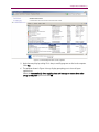
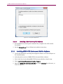
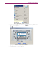
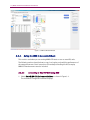
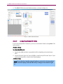
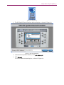
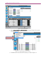
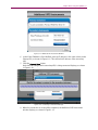
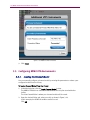
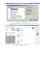
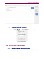
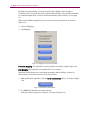
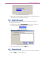
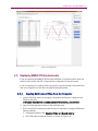
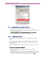
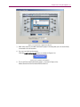
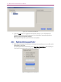
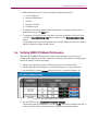
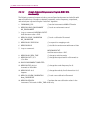
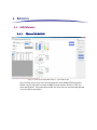
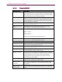
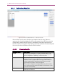
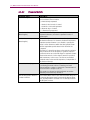
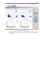
MIMO OTA Environment Builder
User Manual
Spirent
541 Industrial Way West
Eatontown, NJ 07724 USA
Email: [email protected]
Web: http://www.spirent.com
AMERICAS 1-800-SPIRENT • +1-818-676-2683 • [email protected]
EUROPE AND THE MIDDLE EAST +44 (0) 1293 767979 • [email protected]
ASIA AND THE PACIFIC +86-10-8518-2539 • [email protected]
This manual applies to MIMO OTA Environment Builder Version 1.10 or higher.
Page Part Number: 71-006654, Version A2
Copyright © 2012 Spirent. All Rights Reserved.
All of the company names and/or brand names and/or product names referred to in this document, in particular, the
name “Spirent” and its logo device, are either registered trademarks or trademarks of Spirent plc and its
subsidiaries, pending registration in accordance with relevant national laws. All other registered trademarks or
trademarks are the property of their respective owners.
The information contained in this document is subject to change without notice and does not represent a
commitment on the part of Spirent. The information in this document is believed to be accurate and reliable;
however, Spirent assumes no responsibility or liability for any errors or inaccuracies that may appear in the
document.
Table of Contents
1.
Introduction ....................................................................................... 1
1.1.
2.
Overview ........................................................................................... 1
Installation......................................................................................... 2
2.1.
Overview ........................................................................................... 2
2.2.
2.3.
MIMO OTA for New Systems ............................................................... 2
MIMO OTA for Existing Systems .......................................................... 2
2.3.1. Upgrading VR5 Software on the Instrument .............................................. 2
2.3.2. Upgrading VR5 Software on the Controller Laptop .................................... 4
2.3.3. Installing MIMO OTA Environment Builder Software ................................. 6
2.4.
Updating the VR5 Password ............................................................... 8
2.4.1. Installing the MIMO OTA Password File .................................................... 8
2.4.2. Connecting the Dongle............................................................................. 9
3.
Using MIMO OTA Environment Builder Software ............................... 10
3.1.
Overview ......................................................................................... 10
3.2.
Modes of Operation ......................................................................... 10
3.2.1. Using the MEB in Localhost Mode .......................................................... 10
3.2.2. Using the MEB in Connected Mode ......................................................... 12
3.3.
Configuring MIMO OTA Environments ............................................... 18
3.3.1. Loading the Channel Model ................................................................... 18
3.3.2. Configuring Chamber Parameters .......................................................... 20
3.3.3. Configuring Base Station Parameters ..................................................... 20
3.3.4. Configuring RF Setup Parameters ........................................................... 21
3.4.
Building MIMO OTA Environments .................................................... 21
3.4.1. Build Environment - Mapping Algorithms ............................................... 21
3.4.2. Saving the Environment ......................................................................... 23
3.4.3. Viewing the Results ............................................................................... 23
3.5.
Replaying MIMO OTA Environments .................................................. 25
3.5.1. Copying Environment Files from the Computer ....................................... 25
3.5.2. Copying Environment Files to the VR5 ..................................................... 26
3.5.3. Loading Environments ........................................................................... 26
ii | MIMO OTA Environment Builder User Manual
3.5.4. Real-time Environment Control ............................................................... 28
4.
3.6.
Verifying MIMO OTA Model Performance ........................................... 29
3.7.
Remote Control ................................................................................ 30
Reference ......................................................................................... 35
4.1.
GUI Reference .................................................................................. 35
4.1.1. Channel Model Tab ................................................................................ 35
4.1.2. Chamber Setup Tab ............................................................................... 37
4.1.3. Calibration Data Tab .............................................................................. 38
4.1.4. Base Station Tab .................................................................................... 39
4.1.5. Plots Tab ............................................................................................... 41
4.1.6. Details Tab ............................................................................................ 42
4.1.7. RF Setup Parameters .............................................................................. 43
1. Introduction
1.1. Overview
The Spirent MIMO OTA Environment Builder (MEB) is a PC-based application designed to
create MIMO OTA models that can be emulated on the Spirent VR5 Spatial Channel
Emulator. MIMO OTA Environment Builder allows you to select from various user-defined
or industry-standard MIMO channel models, chamber configurations, and base station
parameters to build complex models. The software is easy to use, and provides many
graphical and tabular outputs to help you understand various aspects of the emulated
MIMO OTA environment.
This manual provides information on installing the software, building environments, and
downloading them to the VR5 hardware.
Figure 1-1: MIMO OTA Environment Builder Window
2. Installation
2.1. Overview
MIMO OTA Environment Builder is designed to be installed on any 64-bit Microsoft
Windows 7 computer. The software is not supported on Windows XP or 32-bit Windows 7
computers. If MIMO OTA Environment Builder is purchased with a new Spirent VR5, it
comes installed on the included laptop. If you purchase MIMO OTA Environment Builder
after receiving the VR5 instrument, you can install the software onto the laptop using the
procedure below. We do not recommend installing MIMO OTA Environment Builder
directly onto the embedded PC in the VR5.
2.2. MIMO OTA for New Systems
If you purchased MIMO OTA Environment Builder at the same time as your VR5
instrument, the controller laptop comes installed with MIMO OTA software. In this case,
you can skip ahead to Chapter 3 on page 10 of this document to learn how to use your
new software.
2.3. MIMO OTA for Existing Systems
If you are upgrading your system to support MIMO OTA, follow the instructions below.
2.3.1.
Upgrading VR5 Software on the Instrument
1. Repeat the steps in Sections 2.3.1and 2.3.2 for each VR5 units in your MIMO OTA
system.
NOTE: It can take up to 45 minutes for a complete upgrade. At the conclusion of the
procedure, you may be asked to reboot the instrument to complete the upgrades.
We recommend that you extract the zipped installation files to a portable USB
device. These files are needed to update both your Controller Laptop and the
VR5.The location of these files will be referred to as < VR5 Installer Root> throughout
the remainder of this document.
2. Connect a mouse to one of the USB ports on the VR5 front panel.
3. Connect the USB device containing the .vr5lic file into the other USB port on the VR5
front panel.
4. Uninstall any previous versions of VR5 software.
Chapter Two: Installation | 3
5. Select Control Panel>Programs>Uninstall a Program.
6. Right-click VR5 HD Spatial Channel Emulator and click Uninstall from the menu, as
shown in Figure 2-1.
Figure 2-1: Uninstalling the Previous VR5 Software
7. A window may display asking if it is ok to modify programs on the local computer.
Click Yes.
8. The window shown in Figure 2-2 may display prompting you to close all open
applications. Select the Automatically close applications and attempt to restart
them after setup is complete option and click OK.
4 | MIMO OTA Environment Builder User Manual
Figure 2-2: Closing Open Applications
2.3.1.1
Installing a New Version of VR5 Software
1. On the USB device containing the installation files, navigate to the <VR5 Installer
Root> folder.
2. Run the VR5Install.exe file and follow the installation instructions.
3. During the installation process, you may be prompted to upgrade instrument
firmware. Click Yes and allow the new firmware to be installed.
4. If prompted, reboot the instrument.
2.3.2.
Upgrading VR5 Software on the Controller Laptop
1. Connect the USB device containing the unzipped installer to one of the USB ports on
the controller laptop.
2. Uninstall any previous versions of VR5 software.
3. Select Control Panel>Programs>Uninstall a Program.
4. Right-click VR5 Spatial Channel Emulator and click Uninstall from the menu, as
shown in Figure 2-3.
Chapter Two: Installation | 5
Figure 2-3: Uninstalling the Previous VR5 Software
5. A window may display asking if it is okay to modify programs on the local computer.
Click Yes.
6. The window shown in Figure 2-4 may display prompting you to close all open
applications.
Select the Automatically close applications and attempt to restart them after
setup is complete option and click OK.
6 | MIMO OTA Environment Builder User Manual
Figure 2-4: Closing Open Applications
2.3.2.1
Installing a New Version of VR5 Software
1. On the USB device containing the installation files, navigate to the <VR5 Installer
Root> folder.
2. Run the VR5Install.exe file and follow the installation instructions.
2.3.3.
Installing MIMO OTA Environment Builder Software
1. Connect the USB device containing the unzipped installer to one of the USB ports on
the controller laptop.
2. Uninstall previous version of MIMO OTA Environment Builder software.
3. If this is the first time installing MIMO OTA Environment Builder, skip this step.
4. Select Control Panel>Programs>Uninstall a Program.
5. Right-click MIMO OTA Environment Builder and select Uninstall from the menu, as
shown in Figure 2-5.
Chapter Two: Installation | 7
Figure 2-5: Uninstalling the Software
2.3.3.1
Installing a New Version of MEB Software
1. On the USB device containing the installation files, navigate to the MIMO OTA
Environment Builder install directory.
Figure 2-6: Installing the New Software
2. Run the setup.exe file, as shown in Figure 2-6 and follow the instructions to install
the software.
8 | MIMO OTA Environment Builder User Manual
2.4. Updating the VR5 Password
You can update the password through the VR5 front panel or the Controller laptop.
1. If using VR5 front panel, connect a mouse to one of the USB ports on the front panel.
2. Connect the USB device containing the unzipped installer into the other USB port on
the VR5 front panel.
3. From the VR5 GUI menu bar, select Help>Password Utility.
Figure 2-7: VR5 GUI – Help Menu Item
4. The Password Utility window displays, as shown in Figure 2-8.
Figure 2-8: Password Utility Window
5. Click the Browse button and select the .vr5lic password file.
6. Click Apply.
7. A window displays indicating that the password file upgrade is successful.
2.4.1.
Installing the MIMO OTA Password File
A password file for the laptop PC is provided with every purchase of MIMO OTA
Environment Builder.
Copy the provided file to the following directory on your laptop computer:
C:\Program Files (x86)\Spirent Communications\MIMO OTA Environment Builder.
After copying the file, rename the file to: "password".
Chapter Two: Installation | 9
2.4.2.
Connecting the Dongle
Before running MIMO OTA Environment Builder, you must connect the provided hardware
dongle. Connect the hardware dongle to any USB port on the Controller laptop.
Figure 2-9: Connecting the USB Dongle
You are now ready to use the MIMO OTA Environment Builder software.
3. Using MIMO OTA Environment Builder Software
3.1. Overview
This chapter provides information on using the MIMO OTA Environment Builder software.
It includes basic instructions to build and load new environments onto the VR5(s). For
detailed information, including a definition of all the fields and parameters in the MEB,
refer to Chapter 4 on page 35.
3.2. Modes of Operation
MIMO OTA Environment Builder can be used in one of two modes of operation:
1. The Offline or Localhost mode can be used to run the software when not connected
to the VR5. This may be useful when you would like to experiment with MIMO OTA
environment creation from the comfort of your cubicle.
2. Online or Connected mode is used when you are connected to a VR5. The following
sections describe each of these cases in detail.
3.2.1.
Using the MEB in Localhost Mode
This mode can be used when experimenting with building new MIMO OTA environments.
This is the fastest way to create and save new environments.
To launch the application, follow the steps in the sections below.
3.2.1.1
Launching the Application
1. Navigate to C:\Program Files (x86)\Spirent Communications\VR5\.
2. Run the SystemControlServiceHost.exe file.
3. Select Start>MIMO OTA Environment Builder, as shown in Figure 3-1.
The Instrument Configuration window displays.
Chapter Three: Using the Software | 11
Figure 3-1: Windows Menu – Launching the Application
4. In the Instrument Configuration window, type localhost in the PrimaryVR5 IP address
field, as shown in Figure 3-2.
Click OK.
Figure 3-2: Instrument Configuration Window
5. The MEB launches, as shown in Figure 3-3.
12 | MIMO OTA Environment Builder User Manual
Figure 3-3: MIMO OTA Main Window
3.2.2.
Using the MEB in Connected Mode
This mode is used when you are running MIMO OTA tests on one or more VR5 units.
The following sections describe how to copy, load, replay, and verify the performance of
the new environments. Basic instructions for remotely controlling the VR5 to replay
MIMO OTA environments are also included.
3.2.2.1
Connecting to One VR5 Unit using MEB
1. Select Start>MIMO OTA Environment Builder, as shown in Figure 3-1.
The Instrument Configuration window displays.
Chapter Three: Using the Software | 13
Figure 3-4: Windows Menu – Launching the Application
2. In the Instrument Configuration window, type the IP address of the VR5, as shown in
Figure 3-2. Click OK.
Figure 3-5: Instrument Configuration Window
14 | MIMO OTA Environment Builder User Manual
3. The MIMO OTA Environment Builder launches, as shown in Figure 3-3.
Figure 3-6: MIMO OTA Main Window
3.2.2.2
Configuring Multiple VR5 Units
If you have multiple VR5 instruments, you must connect them before loading MIMO OTA
environments.
Hardware Setup
To set up the VR5 units:
1. Connect the HDMI cable that came with the VR5 to digitally synchronize the two
VR5s.
2. Connect from the "Sync Out" port on DSPB 2 on the Primary VR5 to the "Sync In" port
on the secondary VR5 as shown in the following figure
Software Setup
NOTE: Ensure that the Controller Laptop IP address is set to 192.168.0.xxx subnet.
On the Controller Laptop, launch the VR5 GUI by clicking the icon shown in Figure
3-7.
Chapter Three: Using the Software | 15
Figure 3-7: VR5 GUI Icon
1. The VR5 Spatial Channel Emulator window displays, as shown in Figure 3-8.
Figure 3-8: VR5 GUI Start Window
2. In the field Primary VR5 IP Address, enter 192.168.0.151.
3. Click Connect.
The VR5 GUI Main window displays, as shown in Figure 3-9.
16 | MIMO OTA Environment Builder User Manual
Figure 3-9: VR5 GUI Main Window
4. Select Configure>Additional VR5 Instruments, as shown in Figure 3-10 to connect
the secondary VR5 unit.
Figure 3-10: Configuring Additional VR5 Instruments
5. The Additional VR5 Instruments window displays, as shown in Figure 3-11.
Chapter Three: Using the Software | 17
Figure 3-11: Additional VR5 Instruments Window
6. In the Enter IP Address of Unit #2 field, enter an IP address in the same subnet as the
Primary VR5, as shown in Figure 3-11. This will be the IP address of the secondary
VR5.
7. Click the Connect Now button.
A window indicating that the secondary VR5 is being connected displays, as shown
in Figure 3-12.
Figure 3-12: Connecting to Instrument Message
8. When the connection is successfully completed, the Additional VR5 Instruments
window displays, as shown in Figure 3-13.
18 | MIMO OTA Environment Builder User Manual
Figure 3-13: Additional VR5 Instruments
9. Click Close.
3.3. Configuring MIMO OTA Environments
3.3.1.
Loading the Channel Model
You can manually configure a channel model by entering the parameters or select a preconfigured model from the Library.
To load a Channel Model from the Library:
1. In the Main window, click the Load Channel Model button.
The MIMO OTA folder has channel models that are in use by the standardization
bodies.
The User Created folder is where your channel models will be saved.
2. Open the desired folder and select a model, as shown in Figure 3-14.
In this example, the SCME Urban Micro model is used.
Click OK.
Chapter Three: Using the Software | 19
Figure 3-14: Load Channel Model Window
3. The Channel Model tab updates to reflect the newly selected model, as shown in
Figure 3-15.
Figure 3-15: Main Window – Channel Model Tab
20 | MIMO OTA Environment Builder User Manual
3.3.2.
Configuring Chamber Parameters
1. Under the Chamber Setup tab, select the Number of Probes and the Probe Layout,
as shown in Figure 3-16.
Figure 3-16: Chamber Setup Tab
3.3.3.
Configuring Base Station Parameters
1. Under the Base Station tab, select the desired Antenna Configuration, as shown in
Figure 3-17.
Chapter Three: Using the Software | 21
Figure 3-17: Base Station Tab
3.3.4.
Configuring RF Setup Parameters
1. Enter the Carrier Frequency and Nominal Output Level, as shown in Figure 3-18.
Figure 3-18: RF Setup Parameters
3.4. Building MIMO OTA Environments
3.4.1.
Build Environment - Mapping Algorithms
You may build new environments in either Localhost or Connected mode. The procedure
is the same for both modes.
22 | MIMO OTA Environment Builder User Manual
Building new environments in Connected mode takes slightly more time than in
Localhost mode, but avoids the need to copy the environments onto the VR5 instrument.
For a detailed explanation on how to build environments, refer to Section 3.3 on page
18.
There are two different algorithms you can use to build an environment, as shown in
Figure 3-19:
1. Precision Mapping
2. Fast Mapping
Figure 3-19: Mapping and Control Parameters
Precision Mapping: This algorithm is more accurate but may take a little longer to run.
Fast Mapping: This algorithm runs quicker but is a bit coarser.
Real-time Control allows you to vary select parameters after building or loading an
environment. It cannot be used to build an environment.
1. After selecting the algorithm, click the Build Environment button, as shown in Figure
3-20.
Figure 3-20: Build Environment Button
2. The MIMO OTA algorithm now starts running.
During this time a progress bar displays, as shown in Figure 3-21.
Chapter Three: Using the Software | 23
Figure 3-21: MIMO OTA Algorithm Status Bar
3. Depending on the input parameters configured in Section 3.3, the build process can
take a few seconds to several minutes to complete.
3.4.2.
Saving the Environment
After building an environment, save it in the Environment Library for future use by
following the instructions below.
1. In the Main window, click the Save Environment button, as shown in Figure 3-22.
The Save Environment window displays, as shown in Figure 3-23.
Figure 3-22: Save Environment Button
Figure 3-23: Save Environment Window
2. Name the new environment and click the Save button.
3.4.3.
Viewing the Results
After building an environment, you can view the results under the Plots and Details tabs.
1. Select the Plots tab, as shown in Figure 3-24.
24 | MIMO OTA Environment Builder User Manual
a. The plots on the upper half of the window display information about the power
distribution per-path on each antenna probe.
b. The plots on the lower half of the window display theoretical and emulated
Doppler spectra for each of the paths.
Figure 3-24: Plots Tab
2. Select the Details tab, as shown in Figure 3-25.
This tab displays information on the set and expected power levels at each VR5
output and each antenna probe.
Chapter Three: Using the Software | 25
Figure 3-25: Details Tab
3.5. Replaying MIMO OTA Environments
If you are operating the MIMO OTA Environment Builder in Connected mode, when you
build an environment, the VR5 is automatically configured to that environment.
If you are operating in Localhost mode, you need to copy the created environment files
from your computer on to the VR5 using the following procedure.
3.5.1.
Copying Environment Files from the Computer
1. Insert a USB flash drive into the laptop. Using Windows Explorer, navigate to the
following directory:
C:\Program Data\Spirent Communications\VR5\db\mimo_ota\env\user
2. Copy all of the new environments to the USB flash drive.
3. If you cannot find the directory listed above, you may need to change the Windows
Explorer defaults.
a. In Windows Explorer, click Organize>Folder and Search Options.
b. The Folder Options window displays, as shown in Figure 3-26.
26 | MIMO OTA Environment Builder User Manual
c. Select the Show hidden files, folders, and drives option.
Figure 3-26: Folder Options Window
3.5.2.
Copying Environment Files to the VR5
1. Connect a mouse and a USB flash drive to the Primary VR5 front panel.
2. Using Windows Explorer on the VR5, copy the new environment files to the following
location on your VR5 file system:
C:\Program Data\Spirent Communications\VR5\db\mimo_ota\env\user
3. If you cannot find this directory, refer to Step #3 in Section 3.5.1.
3.5.3.
Loading Environments
You can load Environment previously built files using the MIMO OTA Environment
Builder.
In Localhost mode, the "load environment" loads the environment on your computer.
This is useful for studying the Plots and other details of your environment, such as
output power levels.
If you want to run MIMO OTA tests using your environment, you must connect to a VR5
unit.
To load and use environments on VR5 units:
1. When you are ready to load environments onto your VR5, you must be in
“Connected” mode.
2. If you are currently running in “Localhost” mode, close the application and restart
MIMO OTA Environment Builder. When prompted to configure the instrument, enter
the IP address of the Primary VR5, as shown in Figure 3-27 and click OK.
Chapter Three: Using the Software | 27
Figure 3-27: Instrument Configuration Window
3. After a few seconds, the Main window displays indicating that you are successfully
connected to the instrument.
4. You can now load environments.
Click the Load Environment button, as shown in Figure 3-28.
Figure 3-28: Load Environment Button
5. The Load Environment window displays, as shown in Figure 3-29.
Select the desired environment file from the list.
28 | MIMO OTA Environment Builder User Manual
Figure 3-29: Load Environment Window
6. Click the Load button to recall the environment settings on your VR5 hardware.
If there is more than one VR5 instrument, both instruments automatically update
with the correct environment settings.
This operation may take up to one minute to complete.
3.5.4.
Real-time Environment Control
1. After the environment is loaded onto the target instrument(s), you can modify certain
parameters in real-time.
To modify parameters immediately, select Real-time Control Mode after building or
loading your new environment, as shown in Figure 3-30.
Figure 3-30: Mapping and Control Options
Chapter Three: Using the Software | 29
2. After selecting this mode, you can modify the following parameters:
a. Carrier Frequency
b. Nominal Output Level
c. Velocity
d. Direction of Travel
e. Calibration Data
3. To update the above parameters, with the exception of Calibration Data, type in a
new value and press the Enter key.
4. To update the Calibration Data in real-time, manually update the Calibration Table,
or click the Load Calibration Data button followed by the Send Calibration Data
button.
This updates the RF Power Setting table and the output power of the VR5 instrument
with the calibration offsets entered above.
3.6. Verifying MIMO OTA Model Performance
After loading the MIMO OTA environment onto the VR5 hardware, you may want to
confirm correct performance of the model. The procedure below explains a simple way to
ensure the model is behaving correctly.
1. Using a signal generator, inject a CW tone into Port 1 on the Primary VR5.
2. Set the signal generator frequency to match the frequency in your environment.
3. On the VR5 GUI, click the Autoset button on Port A1, as shown in Figure 3-31.
Figure 3-31: RF Setup and Measurement – Autoset
4. On the VR5 GUI, select Configure>Power Meter Settings.
Change the output port settings on Port B1 to 6.9s. This setting configures the VR5 to
take 6.9 seconds worth of measurements using the internal power meters.
30 | MIMO OTA Environment Builder User Manual
Figure 3-32: Output Port Settings – Number of Averages
5. Wait for at least one minute for the averaging of the signal to be completed.
Record the value of the power level displayed at the outputs of MIMO Channel #1
(Ports B1 and B2).
6. In MIMO OTA Environment Builder, select the Details tab. Under the Expected Power
column, verify the Power Level at Probe ID 1H - 3dB matches the measured power at
B1, and that Probe ID 1V - 3dB matches the measured power at B2, as shown in
Figure 3-33.
Figure 3-33: Details Tab – RF Power Setting
NOTE: If you are using an LTE signal, then the power in the Details table will exactly
match the measured power in the VR5 GUI. In that case there is no need to subtract
3dB from the expected power.
If the velocity in your model is slow (<10km/hr), it may be necessary to increase the
number of averages for a stable result.
3.7. Remote Control
It is possible to build new applications that utilize MIMO OTA capabilities within the VR5.
This section provides details about building these applications. Before proceeding with
this section, you should create and download new environments using the instructions
provided in this document.
The diagram shown in Figure 3-34 illustrates the necessary hardware configuration to
create a custom MIMO OTA application. In this configuration, the custom application
uses TCP/IP communications to remotely control the VR5 hardware system.
Chapter Three: Using the Software | 31
Figure 3-34: Hardware Setup for Custom Application Diagram
3.7.1.1
Communications Transport
VR5 supports remote programming through TCP/IP communications. By default, the VR5
embedded PC is listening on port 3000 for requests from remote applications. To control
one or more VR5 instruments in a system, your application should only send commands
to the primary VR5. The default IP address for the primary VR5 is: 192.168.0.100.
32 | MIMO OTA Environment Builder User Manual
3.7.1.2
Remote Programming Interface (RPI) Commands for MIMO OTA
The following table contains a list of relevant remote commands to configure MIMO OTA
in your VR5 system. For a complete list of remote commands, refer to the VR5 HD Spatial
Channel Emulator User Manual.
Command
Description
Default Value
Range of Values
*IDN?
Queries the identity of the
instrument
ERR?
Polls for any errors generated in
the instrument
MEB:CMB:LIB <filename>
Loads the Chamber Setup
named <filename>
DEFAULT
MEB:CMB:LIB?
Queries the name of the current
Chamber Setup file
DEFAULT
MEB:CMB:LIBAV?
Returns the list of Chamber
Setups available in the Chamber
Library
MEB:CAL:LIB <filename>
Loads the amplitude calibration
data file identified by the
<filename> parameter.
MEB:ENV:OUTP <value>
Sets the nominal output power
level of the MEB. This
determines the set point used to
calculate the actual power levels
of the output ports of the VR5.
This command can be used only
in real-time mode.
-30.0
-20.0 to -110.0
MEB:ENV:VEL <value>
Sets the MS velocity for all paths
to the <value> in km/hr. This
command can be used only in
real-time mode.
10.0
0 to 5400.0
MEB:ENV:DOT <value>
Sets the MS direction of travel in
degrees for all paths. This API
can be called in real-time mode.
0.0
-180.0 to 180.0
MEB:ENV:FREQ <value>
Sets the carrier frequency in
MHz of all VR5 output ports used
in the current MIMO OTA
environment. This command can
be used only in real-time mode.
2600.0
380.0 to 6000.0
MEB:ENV:ALG <value>
Sets the algorithm type for the
MIMO OTA Environment Builder.
PRECISION
PRECISION, FAST,
REAL_TIME
MEB:ENV:SENDCAL
Sets the Amplitude Calibration
values. This command can be
used only in real-time mode.
MEB:ENV:BUILD
Builds the MIMO OTA
environment and configures the
VR5 accordingly.
Chapter Three: Using the Software | 33
Command
Description
MEB:ENV:BDSTAT?
Queries the build status.
MEB:ENV:LIB <filename>
Loads the environment file
identified by the <filename>
parameter.
MEB:ENV:LDSTAT?
Queries the Load status.
MEB:ENV:LIB?
Queries the name of the current
environment file.
MEB:ENV:LIBAV?
Returns the list of environments
available in the Environment
Library.
FADM
Sets the fading mode of the VR5
instrument
MEB:ENV:SETPower?
Returns a comma-separated list
of set power levels for each of
the VR5 output ports used in the
current MIMO OTA environment.
This command can be used only
in real-time mode..
MEB:ENV:EXPPower?
Returns a comma-separated list
of expected power levels for
each of the VR5 output ports
used in the current MIMO OTA
environment. This command can
be used only in real-time mode..
Default Value
Range of Values
IDLE, COMPuting,
INStrumentConfig
DEFAULT
IDLE, COMPuting,
INStrumentConfig
DEFAULT
CLASSICAL
CLASSICAL,
GEOMETRIC,
MIMO_OTA
34 | MIMO OTA Environment Builder User Manual
3.7.1.3
Sample Command Sequence to Program MIMO OTA
Functionality
The following command sequence loads a pre-configured environment and rebuilds with
new calibration data. Changes to selected parameters such as frequency, output level,
and velocity are adjusted using the “real-time” algorithm.
1. FADM:MIMO_OTA
//sets the instrument to MIMO OTA mode
2. MEB:ENV:LIB MY_ENVIRONMENT
MY_ENVIRONMENT
// loads an environment named
3. Loop on command: MEB:ENV:LDSTAT?
Until the return value = IDLE.
4. MEB:CAL:LIB MY_CALIBRATION
MY_CALIBRATION
// loads a calibration file named
5. MEB:ENV:ALG PRECISION
// use precision mapping mode
6. MEB:ENV:BUILD
// rebuilds the environment with new cal data
7. Loop on command:
MEB:ENV:BDSTAT?
Until the return value = IDLE.
8. MEB:ENV:ALG REAL_TIME
// change to real-time mode
9. MEB:ENV:OUTP -37.0
37.0 dBm
// change the output level for all channels to -
10. BUILD ENVIRONMENT COMPLETED.
11. MEB:ENV:FREQ 2140.0
channels to 2140 MHz
// change the carrier frequency for all
12. MEB:ENV:VEL 40.5
degrees
// change the velocity for all channels to 40.5
13. MEB:CAL:LIB NEW_CALIBRATION
New_CALIBRATION
// loads a new calibration file named
14. MEB:ENV:SENDCAL
//updates the new calibration values in the
instrument. This works in REAL_TIME mode only.
4. Reference
4.1. GUI Reference
4.1.1.
Channel Model Tab
Figure 4-1: Environment Builder Main Window – Channel Model Tab
This tab allows you to load, save, and edit channel models. MIMO OTA Environment
Builder comes loaded with a number of MIMO channel models defined in 3GPP and
other specifications. The power/delay profile and other plots are automatically updated
as you modify the parameters.
36 | MIMO OTA Environment Builder User Manual
4.1.1.1
Parameter Details
Parameter Name
Description
Number of Paths
This parameter specifies the number of delay taps in the channel
impulse response and is normally specified by the channel model.
Each path is assumed to experience "frequency flat" fading, which
is also referred to as a zero delay spread cluster
Power Angle Spectrum
The shape of the cluster may be selected from: Laplacian,
Gaussian, or Uniform distributions. The Cluster PDF describes the
Power Angle Spread of the received signal. The Transmit signal is
always specified as a Laplacian.
Velocity (km/hr)
Emulated Mobile Velocity that is used to time evolve the fading
samples within the test volume
MS Direction of travel
(deg)
Emulated Direction for travel, which determines the Doppler
characteristics of the signals in the test volume
XPR (dB)
Power Ratio in dB of the polarized signal.
XPRv = Pvv/Pvh
XPRh = Phh/Phv
For practical modeling, XPRv = XPRh is assumed.
BS Angle Spread (deg)
The second central moment of the normalized power weighted
angle profile of a Path leaving the Base Station
AoA (deg)
Average angle of the arriving path at the test volume
Relative Path Loss (dB)
Difference in path loss observed between path delays of the power
delay profile or channel impulse response
Delay (microseconds)
Time of arrival of the path delays measured from the first arriving
path in units of microseconds
AoD (deg)
Average angle of the departing path with respect to the bore-sight
of the emulated Base Station antenna array
Mid-paths enabled?
Paths are split into mid-paths that are slightly delayed at reduced
power; the total path power remains the same, but a small amount
of delay spread is observed. This produces some frequency
selectivity which improves the path model when the channel
bandwidth is above 5-10 MHz.
MS Angle Spread (deg)
The second central moment of the normalized power weighted
angle profile of a path arriving at the receiver.
Mid-path powers
(fractional)
Fractional power distribution of the mid-paths that sum to unity.
These values are specified in some standard models like SCME
and Winner II.
Mid-path delays
(microseconds)
Relative delays of each mid-path with respect to the original path
delay.
Chapter Four: Reference | 37
4.1.2.
Chamber Setup Tab
Figure 4-2: Environment Builder Main Window – Chamber Setup Tab
This tab allows you to enter parameters related to a specific Chamber Setup while the
plot updates in real-time. The location of the antenna probes display, numbered in red.
You can load and save different Chamber Setup configurations as needed.
4.1.2.1
Parameter Details
Parameter Name
Description
Number of probes
Counts the number of physical probes, which may consist of one
element (V only) or two elements (V&H).
Probe layout
Select between Circular or Sector layouts.
Path Gain
The path gain represents the normalized gain measured between
the output of the channel emulators and the test volume, where
the receive antenna and cable are removed.
The normalized gain represents the weakest signal measured
during calibration on all of the probe signals. This is the Path gain
for the output that has a calibration offset of 0dB.
This value enables the calculation of the expected output power at
the test volume.
The expected output power is called the "Combined Output" and is
found under the Details tab. The Combined output value is: (dBm)
= Output Power Setting (dBm) + the RF Power Boost (dB) that
results from the channel model +_Path Gain(dB).
38 | MIMO OTA Environment Builder User Manual
4.1.3.
Calibration Data Tab
Figure 4-3: Environment Builder Window – Calibration Data Tab
This tab allows you to enter Calibration Data related to the test setup. This data
represents the normalized path gain in dB from the output of each VR5 channel to the
corresponding antenna probe. The data is normalized to the path of maximum loss.
Enter the maximum loss value in the Path Gain parameter under the Chamber Setup tab.
You can load and save different calibration files as needed.
4.1.3.1
Parameter Details
Parameter Name
Description
Probe #
The probes are numbered in a counter-clockwise direction. The
probe numbering is displayed in the Plots tab for the circular and
sector configurations depending on what is selected.
Vertical
The calibration factors are currently pre-normalized, so that the
weakest of all of the output calibrations is not changed by the
calibration and is assigned 0dB. The stronger paths are assigned
values in negative dBs of gain that results in the same output
power after the calibration offsets are applied.
If the model is changed, for example, fewer probes are used; the
set of probes must still contain the 0dB probe. If there are not, the
set must be renormalized.
Horizontal
The Horizontal probe cal factors are specified together with the
vertical probe cal factors.
Chapter Four: Reference | 39
4.1.4.
Base Station Tab
Figure 4-4: Environment Builder Window – Base Station Tab
This tab allows you to specify information related to the base station emulator. You can
load and save base station files as needed.
40 | MIMO OTA Environment Builder User Manual
4.1.4.1
Parameter Details
Parameter Name
Description
Antenna Configuration
There are several base station antenna assumptions that
can be selected. These include:
| | = Vertical Only separated
+ = Vertical + Horizontal co-located
| - = Vertical + Horizontal separated
X = Slant 45 deg co-located
\ / = Slant 45 deg separated
Base Station Antenna Distance
(Wavelengths)
For those antenna configurations above that include
separated elements, the value is specified in units of
wavelengths.
Receiver Antenna Separation
(Wavelengths)
The receiver separation distance is not directly related to
the device under test. For instance, the electrical distance
between receiver elements is not needed to specify this
value. It is the distance at which the ideal spatial cluster
and the equivalent spatial cluster in the chamber are
compared.
The value of 0.5 lambda produces a theoretical correlation
that produces the most sensitivity on spatial correlation
because it varies across the full range for standard clusters.
These values are also in the range observed for practical
device antennas. In this case, 0.5 is the recommended
standard value for the receiver separation, independent of
the device under test.
Remove V to H coupling
Select this option if Vertical-only probes are used without
considering polarization due to scattering, and each
channel emulator output is connected to separate vertical
probes that are in unique locations.
This results in a channel model distributed among the
available probes without polarization.
Remove Base Station Antenna
Correlation effects
Uncorrelated Base Stations are often used when the goal is
to measure the antenna performance at the Device Under
Test, and Base Station Correlation is not directly related to
the DUT performance.
Chapter Four: Reference | 41
4.1.5.
Plots Tab
Figure 4-5: Environment Builder Window – Plots Tab
The plots in the upper half of the table show the fractional power contribution for each
path per antenna probe. The plots in the bottom half of the table illustrate the Doppler
spectra per-path.
42 | MIMO OTA Environment Builder User Manual
4.1.6.
Details Tab
Figure 4-6: Environment Builder Window – Details Tab
This table provides detailed information about power levels in the system. The Detailed
Result parameters are described in the following table.
4.1.6.1
Parameter Details
Parameter Name
Description
Gain over Nominal Output
Power
(dB)
This represents the difference between the sum of all port
powers and the nominal power level. For instance, a
Uniform channel model with equal power on each of 8
probes will have a 10*log10(8) = 9.1 dB output power
boost
Chapter Four: Reference | 43
Parameter Name
Description
Combined Output Power of all
probes (dBm)
This is the expected power level in the test volume due to
the transmission of the nominal set power at the channel
emulators combined with the channel model. This results in
a power boost value with the normalized path gain
included.
The value of the Combined output (dBm) = Output Power
Setting (dBm) + the RF Power Boost (dB) that results from
the channel model + Path Gain(dB).
See also: Path Gain
Set Power
(dBm)
This is the power set point specified on each output port of
the VR5.
This is an analog power setting. By itself, it is only useful as
an intermediate value.
Expected Power
(dBm)
This is the actual output power expected on each output
port of the VR5.It is a combination of analog, digital gains
and calibration offsets.
Probe Angle
(degrees)
Along with the first column identifying the probe number
and polarization, this column specifies the angle that the
probe is located. This probe angle is also given in the polar
plot on the Plot tab.
4.1.7.
RF Setup Parameters
Figure 4-7: RF Setup Parameters
These parameters allow you to configure the frequency and nominal output power of all
channels in the system. After an environment is loaded on the hardware, click the
Autoset button to apply the correct power levels at the output of each channel.