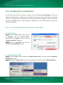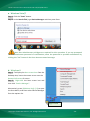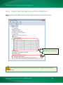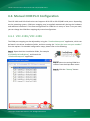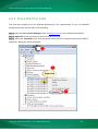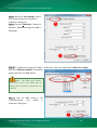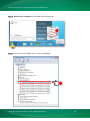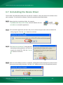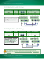
1
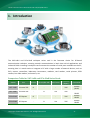
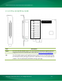
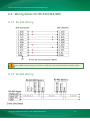
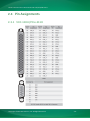
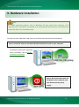
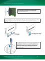
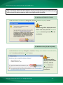
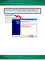
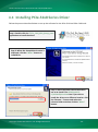
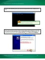
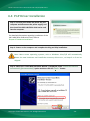
VXC-1x8U/PCIe-S1x8 Series User Manual SSeerriiaall CCoom mm muunniiccaattiioonn BBooaarrdd w wiitthh 88 RRSS--223322//442222//448855 PPoorrttss WARRANTY All products manufactured by ICP DAS are warranted against defective materials for a period of one year from the date of delivery to the original purchaser. WARNING ICP DAS assumes no liability for damages consequent to the use of this product. ICP DAS reserves the right to change this manual at any time without notice. The information furnished by ICP DAS is believed to be accurate and reliable. However, no responsibility is assumed by ICP DAS for its use, nor for any infringements of patents or other rights of third parties resulting from its use. COPYRIGHT Copyright © 2015 by ICP DAS. All rights are reserved. TRADEMARKS Names are used for identification purposes only and may be registered trademarks of their respective companies. CONTACT US If you have any questions, please feel free to contact us at: Email: [email protected], [email protected] We guarantee to give you response within 2 working days. VVeerrssiioonn 11..11..33,, JJaann.. 22001155 SUPPORT This manual relates to the following cards: VXC-118U, VXC-148U PCIe-S118, PCIe-S148 Serial Communication Board with 8 RS-232/422/485 Ports Table of Contents PACKING LIST........................................................................................................................................................................ 3 MORE INFORMATION .......................................................................................................................................................... 3 1. INTRODUCTION ........................................................................................................................................................ 4 1.1 FEATURES .............................................................................................................................................. 5 1.2 SPECIFICATIONS ....................................................................................................................................... 7 1.2.1 VXC-118U/PCIe-S1x8 ..................................................................................................................................... 7 1.2.2 VXC-148U/PCIe-S148 .................................................................................................................................... 8 1.3 2. OPTIONS ............................................................................................................................................. 9 HARDWARE CONFIGURATION................................................................................................................................. 10 2.1 BOARD LAYOUT..................................................................................................................................... 10 2.1.1 VXC-118U/VXC-148U .................................................................................................................................. 10 2.1.2 PCIe-S118/PCIe-S148................................................................................................................................... 11 2.2 WIRING NOTES FOR RS-232/422/485 ...................................................................................................... 12 2.2.1 RS-232 Wiring ............................................................................................................................................. 12 2.2.2 RS-485 Wiring ............................................................................................................................................. 12 2.2.3 RS-422 Wiring ............................................................................................................................................. 13 2.3 PIN ASSIGNMENTS ................................................................................................................................. 14 2.3.1 VXC-118U/PCIe-S118 .................................................................................................................................. 14 2.3.2 VXC-148U/PCIe-S148 .................................................................................................................................. 15 3. HARDWARE INSTALLATION ..................................................................................................................................... 16 4. SOFTWARE INSTALLATION ...................................................................................................................................... 20 4.1 OBTAINING THE DRIVER INSTALLER PACKAGE................................................................................................. 20 4.2 INSTALLING VXC-1X8U SERIES DRIVER........................................................................................................ 21 4.3 INSTALLING PCIE-S1X8 SERIES DRIVER ........................................................................................................ 24 4.4 PNP DRIVER INSTALLATION ...................................................................................................................... 26 4.5 VERIFYING THE INSTALLATION ................................................................................................................... 28 4.5.1 Accessing Windows Device Manager .......................................................................................................... 28 4.5.2 Check the Configuration of the COM Port ................................................................................................... 30 4.6 MANUAL COM PORT CONFIGURATION ....................................................................................................... 31 4.6.1 4.6.2 4.7 5. VXC-118U/VXC-148U .................................................................................................................................. 31 PCIe-S118/PCIe-S148................................................................................................................................... 33 UNINSTALLING THE DEVICE DRIVER ............................................................................................................. 36 TESTING THE MULTIPORT SERIES CARD ................................................................................................................ 37 5.1 SELF-TEST WIRING ................................................................................................................................. 37 5.2 EXECUTE THE TEST PROGRAM.................................................................................................................... 39 Copyright © 2015 ICP DAS CO., Ltd. All Rights Reserved. -2- Serial Communication Board with 8 RS-232/422/485 Ports Packing List The shipping package includes the following items: Note: One VXC-1x8U or PCIe-S1x8 Series Card If any of these items are missing or damaged, please contact the local distributor for more Quick Start One Quick Start Guide information. Save the shipping materials and cartons in case you need to ship the card in the One Software Utility CD future. One CA-PC62M Connector More Information Manual/DataSheet/QuickStart: CD:\NAPDOS\multiport\document http://ftp.icpdas.com/pub/cd/iocard/pci/napdos/multiport/document/ Software/Drivers: CD:\NAPDOS\multiport\windows http://ftp.icpdas.com/pub/cd/iocard/pci/napdos/multiport/windows/ Software/Test2COM/Utility: CD:\NAPDOS\multiport\utility http://ftp.icpdas.com/pub/cd/iocard/pci/napdos/multiport/utility/ Copyright © 2015 ICP DAS CO., Ltd. All Rights Reserved. -3- Serial Communication Board with 8 RS-232/422/485 Ports 1. Introduction The VXC-1x8U and PCIe-S1x8 multiport series card is the foremost choice for PC-based communication solutions, ensuring smooth communication in both time-critical applications and industrial fields. Installing a multiport card increases the number of serial ports available on the PC, meaning that it is much easier to integrate a PC with a large number of external devices, such as PLCs, meters, controllers, laboratory instruments, modems, card readers, serial printers, RFID readers, bar code readers, and sensors, etc. Comparison Table for VXC-1x8U and PCIe-S1x8 Series Cards: Model Bus RS-232 RS-422/RS-485 Self-Tuner FIFO Size (bytes) VXC-118U Universal PCI 8 - - 256 VXC-148U Universal PCI - 8 Yes 256 PCIe-S118 PCI Express 8 - - 256 PCIe-S148 PCI Express - 8 Yes 256 Copyright © 2015 ICP DAS CO., Ltd. All Rights Reserved. Connector Female DB-62 Female DB-62 Female DB-62 Female DB-62 -4- Serial Communication Board with 8 RS-232/422/485 Ports 1.1 Features Universal PCI (3.3 V/5 V) for VXC-1x8U Series Card The Universal PCI card works with both newer 3.3 V PCI bus that is widely-used in servers, and the traditional 5 V PCI bus. The Universal PCI interface will be the standard for every card developed by ICP DAS in the near future. PCI Express for PCIe-S1x8 Series Card PCI Express (PCIe) is a computer expansion card standard. A key difference between PCIe and earlier PC buses is a topology based on point-to-point serial links, rather than shared parallel bus architecture. Conceptually, the PCIe bus can be thought of as a 'high-speed serial replacement' of the older PCI/PCI-X bus. Hardware FIFO up to 256 bytes FIFO is an acronym for "First In, First Out", and is a method used for organizing and manipulating data relative to time and prioritization. FIFO is used for buffering and flow control while the data is transmitted from the hardware to the software. When using a hardware FIFO (buffer), a small delay in either the software or the operating system will not cause any data loss. VXC-1x8U/PCIe-S1x8 series cards are equipped with a large 256-byte hardware FIFO for each port. A large hardware FIFO is useful for preventing data loss if the loading on your system is heavy, e.g. while running a multi-task operating system, such as Windows, or Linux, etc. Copyright © 2015 ICP DAS CO., Ltd. All Rights Reserved. -5- Serial Communication Board with 8 RS-232/422/485 Ports Self-Tuner The VXC-148U/PCIe-S148 card is equipped with an internal “Self-Tuner” chip that is used to automatically control the direction of the transmission and receiving of signals on the RS-485 ports. Without the help inclusion of the Self-Tuner, the RS-485 transmitter would need to be manually enabled before transmitting, and then disabled once the transmission is complete. The timing method that is used to enable and disable the transmitter (direction control) is major source of many communication problems, and is very difficult to rectify. The built-in Self-Tuner embedded on the VXC-148U/PCIe-S148 card can help effectively any issues related to direction control and also simplifies the software programming required for communication applications. Automatically Select COM Port Numbers The VXC-1x8U/PCIe-S1x8 series card support drivers choose an available COM port number automatically. Users can specify the COM port number of the VXC-1x8U/PCIe-S1x8 card under software control. Various Accessories There are a lot of optional accessories for the VXC-1x8U and PCIe-S1x8 multiport series cards, such as RS-232 cables and daughter boards. These tools make wiring much easily than ever. Copyright © 2015 ICP DAS CO., Ltd. All Rights Reserved. -6- Serial Communication Board with 8 RS-232/422/485 Ports 1.2 Specifications 1.2.1 VXC-118U/PCIe-S1x8 Models PCIe-S118 VXC-118U Communication Port COM1 - COM8 RS-232 (TxD, RxD, RTS, CTS, DTR, DSR, DCD, GND) UART 16c950 compatible Baud Rate 2400 – 921600 bps Data Bits 5, 6, 7, 8 Stop Bits 1, 1.5, 2 Parity None, Even, Odd, Mark, Space FIFO Internal 256 bytes 50 - 115200 bps General Bus Type PCI Express x1 COM-Selector No Connector DB-62 (Female) Power Consumption 120 mA @ 5 V Operating Temperature 0°C ~ +60°C Storage Temperature -20°C ~ +70°C Humidity 0 ~ 90% RH, non-condensing Dimensions (L x W x D) 131 mm x 121 mm x 22 mm Copyright © 2015 ICP DAS CO., Ltd. All Rights Reserved. Universal PCI, 3.3 V/5 V, 33 MHz, 32-bit 132 mm x 121 mm x 22 mm -7- Serial Communication Board with 8 RS-232/422/485 Ports 1.2.2 VXC-148U/PCIe-S148 Models PCIe-S148 VXC-148U Communication Port RS-422/485 The RS-422 and RS-485 Cannot be used simultaneously. RS-422 RS-422 (TxD+, TxD-, RxD+, RxD-, GND) COM1 COM8 2-Wire RS-485 Bias Resistor Nodes RS-485 (Data+, Data-, GND) Yes, 1 KΩ 256 (max.) UART 16c950 compatible Baud Rate 2400 –921600 bps Data Bits 5, 6, 7, 8 Stop Bits 1, 1.5, 2 Parity None, Even, Odd, Mark, Space FIFO Internal 256 bytes 50 - 115200 bps General Bus Type PCI Express x1 COM-Selector No Connector DB-62 (Female) Power Consumption 120 mA @ 5 V Operating Temperature 0°C ~ +60°C Storage Temperature -20°C ~ +70°C Humidity 0 ~ 90% RH, non-condensing Dimensions (L x W x D) 128 mm x 121 mm x 22 mm Universal PCI, 3.3 V/5 V, 33 MHz, 32-bit Note: The combination of 5 data bits and 1.5 stop bits is not supported for a Baud Rate of 921,600 bps for VXC-148U only. Copyright © 2015 ICP DAS CO., Ltd. All Rights Reserved. -8- Serial Communication Board with 8 RS-232/422/485 Ports 1.3 Options Item & Description VXC-118U VXC-148U PCIe-S118 PCIe-S148 CA-9-6210 DB-62 Male(D-sub) to 8-Port DB-9 Male(D-sub) Cable 1 m (180 º) CA-PC09F 9-pin Female D-sub Connector with Plastic Cover CA-PC62M 62-pin Male D-sub Connector with Plastic Cover DN-09-2/DN-09-2F I/O Connector Block with DIN-Rail Mounting and two 9-pin Male Headers CA-0910F 9-pin Female-Female D-sub Cable, 1 m CA-0915 9-pin Male-Female D-sub Cable, 1.5 M Copyright © 2015 ICP DAS CO., Ltd. All Rights Reserved. -9- Serial Communication Board with 8 RS-232/422/485 Ports 2. Hardware Configuration 2.1 Board Layout 2.1.1 VXC-118U/VXC-148U For VXC-148U Only Item Description CON1 RS-232 or RS-422/RS-485 Signal. For more detailed information regarding the pin assignments for the VXC-1x8U series card, refer to Section 2.3 Pin Assignments. JPx The VXC-148U supports pull-high/low jumpers allow the Port1/2/3/4/5/6/7/8 can be selected to either pull-high or pull-low via placement of the JP1/2/3/4/5/6/7/8 jumpers. The JP1/2/3/4/5/6/7/8 default settings: pull-high. Copyright © 2015 ICP DAS CO., Ltd. All Rights Reserved. - 10 - Serial Communication Board with 8 RS-232/422/485 Ports 2.1.2 PCIe-S118/PCIe-S148 For PCIe-S148 Only Item Description CON1 RS-232 or RS-422/RS-485 Signal. For more detailed information regarding the pin assignments for the PCIe-S1x8 series card, refer to Section 2.3 Pin Assignments. JPx The PCIe-S148 supports pull-high/low jumpers allow the Port1/2/3/4/5/6/7/8 can be selected to either pull-high or pull-low via placement of the JP1/2/3/4/5/6/7/8 jumpers. The JP1/2/3/4/5/6/7/8 default settings: pull-high. Copyright © 2015 ICP DAS CO., Ltd. All Rights Reserved. - 11 - Serial Communication Board with 8 RS-232/422/485 Ports 2.2 Wiring Notes for RS-232/422/485 2.2.1 RS-232 Wiring Note: FGND is the frame ground that is soldered to the metal shield on the DB-9 cable. 2.2.2 RS-485 Wiring Copyright © 2015 ICP DAS CO., Ltd. All Rights Reserved. - 12 - Serial Communication Board with 8 RS-232/422/485 Ports 2.2.3 RS-422 Wiring Note: 1. Usually, you have to connect all signal grounds of RS-422/485 devices together to reduce common-mode voltage between devices. 2. Twisted-pair cable must be used for the DATA+/- wires. 3. Both two ends of the cable may require a termination resistor connected across the two wires (DATA+ and DATA-). Typically 120 Ω resisters are used. 4. The Data+ and B pins are positive-voltage pins, and Data- and A pins are negative-voltage pins in the above figure. The B/A pins may be defined in another way depending on devices, please check it first. Copyright © 2015 ICP DAS CO., Ltd. All Rights Reserved. - 13 - Serial Communication Board with 8 RS-232/422/485 Ports 2.3 Pin Assignments 2.3.1 VXC-118U/PCIe-S118 Copyright © 2015 ICP DAS CO., Ltd. All Rights Reserved. - 14 - Serial Communication Board with 8 RS-232/422/485 Ports 2.3.2 VXC-148U/PCIe-S148 Copyright © 2015 ICP DAS CO., Ltd. All Rights Reserved. - 15 - Serial Communication Board with 8 RS-232/422/485 Ports 3. Hardware Installation Note: As certain operating systems, such as Windows XP may require the computer to be restarted after a new driver is installed, it is recommended that the driver is installed first, which will reduce the installation time. To install the VXC-1x8U/PCIe-S1x8 series card, follow the procedure described below: Step 1: Install the driver for the VXC-1x8U/PCIe-S1x8 series card on your computer. For detailed information regarding driver installation, refer to Chapter 4 Software Installation. Step 2: Shut down and switch off the power to the computer, and then disconnect the power supply. Copyright © 2015 ICP DAS CO., Ltd. All Rights Reserved. - 16 - Serial Communication Board with 8 RS-232/422/485 Ports Step 3: Remove the cover from the computer. Step 4: Select an empty PCI/PCI Express slot. Step 5: Unscrew and remove the PCI/PCI Express slot cover from the computer case. Copyright © 2015 ICP DAS CO., Ltd. All Rights Reserved. - 17 - Serial Communication Board with 8 RS-232/422/485 Ports Step 6: Remove the connector cover from the VXC1x8U/PCIe-S1x8 series card. Step 7: Carefully insert the VXC-1x8U/PCIe-S1x8 series card into the PCI/PCI Express slot by gently pushing down on both sides of the card until it slides into the PCI connector. Step 8: Confirm that the card is correctly inserted in the motherboard, and then secure the VXC-1x8U/PCIe-S1x8 series card in place using the retaining screw that was removed in Step 5. Copyright © 2015 ICP DAS CO., Ltd. All Rights Reserved. - 18 - Serial Communication Board with 8 RS-232/422/485 Ports Step 9: Replace the covers on the computer. Step 10: Re-attach any cables, insert the power cord and then switch on the power to the computer. Once the computer reboots, follow the onscreen messages to complete the Plug and Play installation process. For more information, refer to Chapter 4 Software Installation. Copyright © 2015 ICP DAS CO., Ltd. All Rights Reserved. - 19 - Serial Communication Board with 8 RS-232/422/485 Ports 4. Software Installation The VXC-1x8U/PCIe-S1x8 series card can be used with both 32 and 64-bit Windows XP/2003/Vista/7/8 systems, and also supports Plug and Play (PnP) functions for easy installation. This chapter provides detailed description of how to install the drivers for the VXC-1x8U/PCIe-S1x8 series card. 4.1 Obtaining the Driver Installer Package The installer package for the ICP DAS VXC-1x8U/PCIe-S1x8 series driver can be obtained from either the companion CD-ROM, the FTP site, or the ICP DAS web site. The locations and addresses are shown below: CD:\\ NAPDOS\MultiPort\Windows\ ftp://ftp.icpdas.com/pub/cd/iocard/pci/napdos/multiport/windows/ http://ftp.icpdas.com/pub/cd/iocard/pci/napdos/multiport/windows/ Install the appropriate driver for your VXC-1x8U/PCIe-S1x8 series card. Driver Name Suitable Multiport Card VXC_1x8U_Win_Setup_xxx.exe for the VXC-118U and VXC-148U. PCIe_S1x8_Win_Setup_xxx.exe for the PCIe-S118 and PCIe-S148. Copyright © 2015 ICP DAS CO., Ltd. All Rights Reserved. - 20 - Serial Communication Board with 8 RS-232/422/485 Ports 4.2 Installing VXC-1x8U Series Driver Follow the process described below to set up the software for the VXC-118U and VXC-148U card: Step 1: Double-click the “VXC_1x8_Win_Setup_xxxx” application to install the driver. Step 2: When the Setup Wizard screen is displayed, click the “Next>” button to installation. Step 3: Select the folder where the drivers are to be install. The default path is C:\ICPDAS\VXC-1x8. But if you wish to install the drivers to a different location, click the “Browse…” button and select the relevant folder and then click the “Next>” button. Copyright © 2015 ICP DAS CO., Ltd. All Rights Reserved. - 21 - Serial Communication Board with 8 RS-232/422/485 Ports Step 4: The Setup Wizard will then display a warning message asking you to confirm that you wish to install the device software. Refer to the figures below for details. For Windows XP/2003 (32-/64-bit) In the “Hardware Installation” dialog box, click the “Continue Anyway” button. Note: The warning will be displayed several times. In all cases, click the “Continue Anyway” button to proceed with the installation. For Windows Vista/7/8 (32-bit/64-bit) In the “Windows Security” dialog box, check the “Always trust software from ICP DAS Co., Ltd.” Checkbox and click the “Install” button. Note: This warning will be displayed several times. All cases, click the “Install” button to proceed with the installation. Copyright © 2015 ICP DAS CO., Ltd. All Rights Reserved. - 22 - Serial Communication Board with 8 RS-232/422/485 Ports Step 5: Once the driver has been installed, the Setup Wizard will be displayed to advise that the computer must be restarted in order to complete the installation. Select the “No, I will restart the computer later” option, and then click the “Finish” button to exit the Wizard. Copyright © 2015 ICP DAS CO., Ltd. All Rights Reserved. - 23 - Serial Communication Board with 8 RS-232/422/485 Ports 4.3 Installing PCIe-S1x8 Series Driver Follow the process described below to set up the software for the PCIe-S118 and PCIe-S148 card: Step 1: Double-click the “PCIe_S1x8_Win_Setup_xxxx” application to install the driver. Step 2: When the Setup Wizard screen is displayed, click the “Next>” button to installation. Step 3: Select the folder where the drivers are to be install. The default path is C:\ICPDAS\PCIe-S1x8. But if you wish to install the drivers to a different location, click the “Browse…” button and select the relevant folder and then click the “Next>” button. Copyright © 2015 ICP DAS CO., Ltd. All Rights Reserved. - 24 - Serial Communication Board with 8 RS-232/422/485 Ports Step 4: In the installation process, the Command Prompt windows will be displayed, don't care. Note: Please do not close this Command Prompt window in installation process. Step 5: Once the driver has been installed, the Setup Wizard will be displayed to advice that the computer must be restarted in order to complete the installation. Select the “No, I will restart the computer later” option, and then click the “Finish” button to exit the Wizard. Copyright © 2015 ICP DAS CO., Ltd. All Rights Reserved. - 25 - Serial Communication Board with 8 RS-232/422/485 Ports 4.4 PnP Driver Installation Step 1: Correctly shut down and power off your computer and disconnect the power supply, and then install the VXC-1x8U/PCIe-S1x8 series card into the computer. For detailed information regarding installation of the VXC-1x8U/PCIe-S1x8 series card, refer to Chapter 3 Hardware Installation. Step 2: Power on the computer and complete the Plug and Play installation. Note: More recent operating systems, such as Windows Vista/7/8 will automatically detect the new hardware and install the necessary drivers etc., so Steps 3 to 5 can be skipped. Step 3: When the “Found New Hardware Wizard” is displayed, select “Install the software automatically [Recommended]” option and then click the “Next>” button. Copyright © 2015 ICP DAS CO., Ltd. All Rights Reserved. - 26 - Serial Communication Board with 8 RS-232/422/485 Ports Step 4: The “Found new Hardware Wizard” will be displayed to advice that the software installation has been completed. Click the “Finish” button to exit the Wizard. Step 5: If the “Found New Hardware Wizard” dialog box is displayed again, repeat Steps 3 and 4 to complete the installation for all COM ports. Copyright © 2015 ICP DAS CO., Ltd. All Rights Reserved. - 27 - Serial Communication Board with 8 RS-232/422/485 Ports 4.5 Verifying the Installation To verify that the driver was correctly installed, use the Windows Device Manager to view and update the device drivers installed on the computer, and to ensure that the hardware is operating correctly. The following is a description of how access the Device Manager in each of the major versions of Windows. Refer to the appropriate description for the specific operating system to verify the installation. 4.5.1 Accessing Windows Device Manager Windows XP Step 1: Click the “Start” button and then point to “Settings” and click “Control Panel”. Double-click the “System” icon to open the “System Properties” dialog box. Step 2: Click the “Hardware” tab, and then click the “Device Manager” button. Windows Server 2003 Step 1: Click the “Start” button and point to “Administrative Tools”, and then click the “Computer Management” option. Step 2: Expand the “System Tools” item in the console tree, and then click the “Device Manager”. Copyright © 2015 ICP DAS CO., Ltd. All Rights Reserved. - 28 - Serial Communication Board with 8 RS-232/422/485 Ports Windows Vista/7 Step 1: Click the “Start” button. Step 2: In the Search field, type Device Manager and then press Enter. Note that Administrator privileges are required for this operation. If you are prompted for an administrator password or confirmation, enter the password or provide confirmation by clicking the “Yes” button in the User Account control message. Windows 8 Step 1: To display the Start screen icon from the desktop view, hover the mouse cursor over the bottom-left corner of screen. Step 2: Right-click the Start screen icon and then click “Device Manager”. Alternatively, press [Windows Key] +[ X] to open the Start Menu, and then select Device Manager from the options list. Right-click Copyright © 2015 ICP DAS CO., Ltd. All Rights Reserved. - 29 - Serial Communication Board with 8 RS-232/422/485 Ports 4.5.2 Check the Configuration of the COM Port Step 3: Verify that the COM Ports for the VXC-1x8/PCIe-S1x8 series card listed correctly. Installation successful Note: Depending on the operating system, the COM port mapping may be applied automatically. Copyright © 2015 ICP DAS CO., Ltd. All Rights Reserved. - 30 - Serial Communication Board with 8 RS-232/422/485 Ports 4.6 Manual COM Port Configuration The VXC-1x8U and PCIe-S1x8 series card supports 8 RS-232 or RS-422/485 serial ports. Depending on the operating system, COM port mapping may be applied automatically during the hardware and software installation. If the auto-configuration for COM Port is messy or that is not you need, you can change the COM Port mappings by manual configuration. 4.6.1 VXC-118U/VXC-148U The COM port mapping can be adjusted by using the “ComPortRemap.exe” application, which can be found in the driver installation folder, and then setting the “Select the start com port number” from the options. For detailed configuration steps, please refer to the following: Step 1: Open the driver installation folder, for example C:\ICPDAS\VXC-1x8\Driver\, and launch the “ComPortRemap.exe” application. 1 Step 2: Select the starting COM Port number from the drop-down menu. Step 3: Click the “Remap” button. 2 3 Copyright © 2015 ICP DAS CO., Ltd. All Rights Reserved. - 31 - Serial Communication Board with 8 RS-232/422/485 Ports Step 4: Once the remapping has been completed, a window will be displayed indicating the new COM Port numbers. 4 Copyright © 2015 ICP DAS CO., Ltd. All Rights Reserved. - 32 - Serial Communication Board with 8 RS-232/422/485 Ports 4.6.2 PCIe-S118/PCIe-S148 The COM port mapping can be adjusted depending on the requirements of you. For detailed configuration steps, please refer to the following: Step 1: Open Windows Device Manager. Refer to Section 4.5.1 for more detailed information. Step 2: Right click on the serial port of the PCIe-S1x8 series card. Step 3: Select the “Properties” item from the popup menu and the “Communications Port (COM n) Properties” dialog box will be displayed. 1 2 Right-click 3 Copyright © 2015 ICP DAS CO., Ltd. All Rights Reserved. - 33 - Serial Communication Board with 8 RS-232/422/485 Ports Step 4: Select the “Port Settings” item in the “Communications Port (COM n) Properties” dialog box. Step 5: Click the “Advanced…” button to open the “Advanced Settings for COM n” dialog box. 4 5 Step 6: In “Advanced Settings for COM n” dialog box, select the appropriate COM Port number from the “COM Port Number:” drop-down options and click the “OK” button. 6 Note: The COM port display “(in use)” means this COM port is being used. Therefore, please do not select it. Step 7: Click the “OK” button in the “Communications Port (COM n) Properties” dialog box. 7 Copyright © 2015 ICP DAS CO., Ltd. All Rights Reserved. - 34 - Serial Communication Board with 8 RS-232/422/485 Ports Step 8: Restart your computer to complete the configuration. 8 Step 9: Confirm the new COM Ports is correctly displayed. 9 Copyright © 2015 ICP DAS CO., Ltd. All Rights Reserved. - 35 - Serial Communication Board with 8 RS-232/422/485 Ports 4.7 Uninstalling the Device Driver The ICP DAS VXC-1x8U/PCIe-S1x8 series card driver includes a utility that allows the software from your computer. To uninstall the software, follow the procedure described below: Step 1: Open the driver installation folder, for example C:\ICPDAS\VXC-1x8 (or PCIe-S1x8), and then double click the unins000.exe uninstaller application. Step 2: The uninstaller application will then ask you to confirm that you want wish to remove the utility program. Click the “Yes” button to continue. Step 3: The “Remove Shared File?” dialog box will be displayed asking whether you wish to remove the shared file. Click the “Yes to All” button to continue. Step 4: After the uninstallation process is complete, a dialog box will be displayed to notify that the driver was successfully removed. Click the “OK” button to finish the uninstallation process. Copyright © 2015 ICP DAS CO., Ltd. All Rights Reserved. - 36 - Serial Communication Board with 8 RS-232/422/485 Ports 5. Testing the Multiport Series Card This chapter provides detailed information regarding the “self-test” process, which enables the user to confirm whether or not the VXC-1x8U/PCIe-S1x8 series card is operating correctly. Before performing the “self-test”, the hardware and driver installation must be completed. For detailed information regarding hardware and driver installation, refer to Chapter 3 Hardware Installation and Chapter 4 Software Installation. Preparing the device Before beginning the “self-test”, ensure that the following items are available: A DN-09-2 (optional) terminal board A CA-9-6210 (optional) cable A CA-0910F (optional) cable 5.1 Self-test Wiring Step 1: Connect the DN-09-2 terminal board to the VXC-1x8U/PCIe-S1x8 series card using the CA-9-6210 and CA-0910F cables. VXC-118U/148U Card PCIe-S118/S148 Card Copyright © 2015 ICP DAS CO., Ltd. All Rights Reserved. - 37 - Serial Communication Board with 8 RS-232/422/485 Ports VXC-118U/PCIe-S118 Card (RS-232 Wiring): Pin Assignment Pin No. Pin No. Pin Assignment TxD0 3 2 RxD1 RxD0 2 3 TxD1 GND 5 5 GND Step 2: Perform the “self-test” by shorting the RxD, TxD and GND pins of both Port0 and Port1. VXC-148U/PCIe-S148 Card (RS-485 Wiring): Pin Assignment Pin No. Pin No. Pin Assignment Data0- 1 1 Data1- Data0+ 2 2 Data1+ GND 5 5 GND Step 2: Perform the “self-test” by shorting the Port0 Data+ and Port1 Data+, the Port0 Data- and Port1 Data- pins and the Port0 GND and Port1 GND pins. Note: For detailed information regarding wiring and pin assignments for the RS232/422/485, refer to Section 2.2 Wiring Notes for RS-232/422/485 and Section 2.3 Pin Assignments. Copyright © 2015 ICP DAS CO., Ltd. All Rights Reserved. - 38 - Serial Communication Board with 8 RS-232/422/485 Ports 5.2 Execute the Test Program Step 1: Execute the “Test2COM.exe” application, which can be found on the companion CD at: CD\Napdos\multiport\utility Or download it from: http://ftp.icpdas.com/pub/cd/iocard/pci/napdos/multiport/utility/ Step 2: Set the appropriate COM Ports, Baud Rate and Data Format information to the values shown in the image below. 1: COM Ports: Enter COM3(First), COM4(Second). 4: Stop Bits: Check “1” 2: Data Bits: Check “8” 3: Parity: Check “None” 5: Baud Rates: Check values 9600 to 115200 6: Loop: Type “1” 7: Click the “Start Test” button to begin the test. 1 2 3 4 5 6 Copyright © 2015 ICP DAS CO., Ltd. All Rights Reserved. 7 - 39 - Serial Communication Board with 8 RS-232/422/485 Ports Notes: 1. Depending on the operating system, COM port mapping may be applied automatically. You should first confirm the number of the COM Port for VXC-1x8U/PCIe-S1x8 series card through Device Manager (see Section 4.5 Verifying the Installation) and then test this COM Port using the Test2COM.exe application. 2. The Baud Rate and Data Format settings used in the Test2COM application depend on the COM ports being used by the VXC-1x8U/PCIe-S1x8 series card. Refer to Section 1.2 Specifications for more detailed information. Step 3: Refer to the test results. If the test was successful, the message “Failed Test: 0” will be displayed. The “self-test” process is now complete and your COM port program can now be operated using this extended COM Port. Test Successful Copyright © 2015 ICP DAS CO., Ltd. All Rights Reserved. - 40 -