1
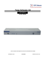
Temp Defender G2
USER MANUAL
D-PK-TDFG2
Visit our website at www.dpstelecom.com for the latest PDF manual and FAQs.
November 22, 2013
D-UM-TDFG2
Firmware Version 1.0A
Revision History
November 22, 2013 Added Conditional Halt, ~evalMt & corrected ~evalMn in
Provisioning Sensors
November 13, 2013 Added ~intCnt mode description
November 8, 2013
Fixed timing on ~evailMn mode to 15 sec
October 10, 2013
Modbus and Sensor clarifications
October 4, 2013
Sensor slot equation explanation, tables and examples
October 3, 2013
Added images and instructions for Modbus functionality
September 6, 2013
Updated Images, Specifications, Shipping List & Misc. Details
for G2
August 20, 2013
Updated Images & Misc. Details
August 15, 2013
Updated Specifications and Images
August 14, 2013
Initial Release
This document contains proprietary information which is protected by copyright. All rights are reserved. No part of this
document may be photocopied without prior written consent of DPS Telecom.
All software and manuals are copyrighted by DPS Telecom. Said software and manuals may not be reproduced, copied,
transmitted or used to make a derivative work, by either mechanical, electronic or any other means in whole or in part, without
prior written consent from DPS Telecom, except as required by United States copyright laws.
© 2013 DPS Telecom
Notice
The material in this manual is for information purposes and is subject to change without notice. DPS Telecom shall not be
liable for errors contained herein or consequential damages in connection with the furnishing, performance, or use of this
manual.
Contents
Visit our w ebsite at w w w .dpstelecom .com for the latest PDF m anual and FAQs
1 TempDefender G2 Overview
1
2 Specifications
3
3 Shipping List
4
3.1 Optional Shipping Items - Available by Request
4 Installation
5
6
4.1 Tools Needed
6
4.2 Mounting
6
4.3 Power Connection
7
5 Temp Defender G2 Front Panel
8
6 Quick Start: How to Connect to the Temp Defender G2
9
6.1 ...via Craft Port (using TTY Interface)
9
6.2 ...via LAN
15
7 TTY Interface
16
7.1 Configure Serial Port via TTY
8 Quick Turn Up
17
17
8.1 How to Send Email Notifications
18
8.2 How to Send SNMP Traps
20
9 Provisioning Menu Field Descriptions
22
9.1 System
23
9.2 User Profiles
24
9.3 Ethernet
25
9.4 Serial Port
26
9.5 SNMP
27
9.6 Notifications
28
9.6.1
Notification Settings
28
9.6.2
Schedule
29
9.7 Alarms
30
9.8 Controls
31
9.9 User Analogs
32
9.10 Sensors
33
9.11 Ping Targets
36
9.12 System Alarms
37
9.13 Timers
38
9.14 Date and Time
39
10 Monitoring via the Web Browser
10.1 Alarms
40
40
10.2 Controls
41
10.3 Sensors
42
10.4 User Analogs
43
10.5 Ping Targets
44
10.6 System Alarms
45
10.7 Graph
46
11 Device Access Descriptions
48
12 Backup Configuration
49
13 Firmware Upgrade
50
14 Reference Section
51
14.1 Display Mapping
51
14.2 System Alarms
59
14.3 SNMP Manager Functions
60
14.4 SNMP Granular Trap Packets
61
15 Frequently Asked Questions
62
15.1 General FAQs
62
15.2 SNMP FAQs
63
16 Technical Support
64
17 End User License Agreement
66
1
1
TempDefender G2 Overview
The TempDefender G2
Could you estimate how much money your company has invested in your IT server room or data
center? How much is your network uptime worth to you? These questions might be difficult to answer,
but monitoring your valuable IT equipment certainly doesn’t have to be.
You need a compact, simple, and reliable device to monitor basic environmental conditions (like
temperature, humidity, smoke...) around your valuable equipment. Without this basic visibility, it’s just a
matter of time before your investment in your server room is seriously damaged.
8 Discrete Alarm Inputs
1 to 4 D-Wire sensor input jacks (Build option), supporting up to 32 sensors (sold separately)
3 Control Relay Outputs (Build option)
Fast, integrated web browser
32 ping targets to monitor other devices on the network
Meet the TempDefender G2
This small device keeps tabs on all the environmental levels that affect your servers, phone closets,
data centers, and other equipment locations. The 8 discrete alarms on the back panel are used to
monitor dry contacts, such as motion sensors, UPS, smoke detectors, flood sensors, AC and room
entry.
What’s the current room temperature? When was the last time someone entered the room? Get all of
this information - right from your network PC.
Don’t wait until the day your AC unit fails and your server closet overheats to start protecting your
gear. This small, 1RU device alerts you of changing conditions 24 hours a day, 7 days a week, either to
your cell or SNMP manager. The TempDefender G2 is the cost-effective way to stay proactive in your
monitoring.
2
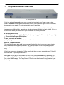
Common Applications for the TempDefender G2
The TempDefender G2 reports alarms as SNMP traps over LAN and supports DCP polling over RS-232, RS-485 or
LAN. The TempDefender G2 supports simultaneous SNMP and DCP operation.
The TempDefender G2 supports both LAN and serial port connectivity. The LAN connection and serial port can be
used at the same time to support simultaneous SNMP and DCP alarm reporting. However, only one DCP channel
can be used, therefore the TempDefender G2 cannot simultaneously report DCP over LAN and DCP over serial port
connection.
In addition to its 8 discrete input points, the TempDefender G2 has 3 control relays, all form A, user defined NO/NC
with short, 8 analogs, and dwire. The control relays allow network administrators to respond remotely to threats to
system integrity. Using the control relays, network administrators can turn on backup generators, open doors and
gates for emergency access, reboot equipment, or perform other functions. The TempDefender G2 also allows you
to reverse the logic state of the alarm on a point by point basis for discrete alarms.
Another feature of the TempDefender G2 is user-defined alarm qualification times. This will allow you to clearly
distinguish momentary status changes from serious problems.
3
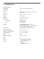
2
Specifications
Discrete Alarm Inputs:
8
Control Relays:
3 (Form A) user defined NO/NC (Optional)
Ping Targets:
32
Protocols:
SNMPv1, SNMPv2c, SNMPv3, DCPx, TELNET, HTTP,
HTTPS, Email
Dimensions:
17.026" W x 1.720" H x 5.136" D
Weight:
3.5 lbs (1.56 kg)
Mounting:
19" or 23" rack or wall mount
Power Input:
-48VDC (-36 to -72 VDC)
Current Draw:
100mA @ 48 VDC
200mA @ 24 VDC
Fuse:
3/4 Amp GMT Fuse
Interfaces:
1 RJ45 10/100BaseT full-duplex Ethernet port
1 USB front-panel craft port
1-4 RJ11 connector for D-Wire sensor network (Optional)
1 Serial port: RS232 or RS485 (Optional)
Visual Interface:
8 Front Panel LEDs, 1 push button, 5 back LED's
Operating Temperature:
32° - 140° F (0° - 60° C)
Industrial Temperature Option:
-22° to 158° F (-30° to 70° C)
Operating Humidity:
0% - 95% non-condensing
MTBF:
60 years
Windows Compatibility:
XP, Vista, 7 (32 or 64 bit)
RoHS
5/6
Sensors:
Up to 32 dwire sensors (8 per plug)
-1 built-in temp sensor (Optional)
Analogs:
8 analog inputs (Optional)
6 user
1 power input
1 temperature / power input
4
3
Shipping List
Please make sure all of the following items are included with your TempDefender G2. If parts are missing, or if you
ever need to order new parts, please refer to the part numbers listed and call DPS Telecom at 1-800-622-3314.
TempDefender G2 IT
D-PK-TMPDF
TempDefender G2 Resource CD
TempDefender G2 IT User Manual
D-UM-TDFG2
6 ft. USB Download Cable
D-PR-046-10A-06
x3
½-Amp GMT Fuses
2-741-00500-00
x2
Lg. Power Connector (Main Pwr)
2-820-00862-02
x2
19" Rack Ear
D-CS-325-10A-00
23" Rack Ear
D-CS-325-10A-01
x8
Four 3/8" Ear Screws
1-000-60375-05
x4
Two Metric Rack Screws
2-000-80750-03
x2
5
x4
Two Standard Rack Screws
1-000-12500-06
Pads
2-015-00030-00
14ft. Ethernet Cable
D-PR-932-10B-14
3.1
Optional Shipping Items - Available by Request
Temp Sensor Node
D-PK-DSNSR-12001
Small WAGO connector
2-802-01020-00
Temp/Humidity Sensor Node
D-PK-DSNSR-12002
6
4
4.1
Installation
Tools Needed
To install the TempDefender G2, you'll need the following tools:
Phillips No. 2 Screwdriver
Small Standard No. 2 Screwdriver
PC with terminal emulator,
such as HyperTerminal
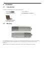
4.2
Mounting
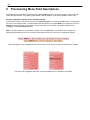
The TempDefender G2 can be flush or rear-mounted
The TempDefender G2 mounts in a 19" rack or a 23" rack using the provided rack ears for each size. Two rack ear
locations are provided. Attach the appropriate rack ears in the flush-mount or rear-mount locations shown in
Figure 6.2.1.
Note: Rack ears can be rotated 90° for wall mounting or 180º for other mounting options (not shown).
7
4.3
Power Connection
The TempDefender G2 uses single or dual (Optional) power inputs, powered through two barrier plug power
connectors.
TempDefender G2 Power Terminals and Fuses
To connect the TempDefender G2 to a power supply:
1. Locate the metal grounding lug next to the symbol
. Use the grounding lug to connect the unit to earth
ground.
2. Insert the eyelet of the earth ground cable between the two nuts on the grounding lug (Ground cable not included).
3. Choose a barrier plug power connector to attach your power cable to. One plug is used for main power and the
other is used for backup power. Both plugs are interchangeable so it does not matter which plug you select. Each
plug's right terminal is Ground and its left terminal is Battery Lead.
4. Insert a battery ground into the power connector plug's right terminal (GND) and tighten the screw.
5. Insert a battery lead to the plug's left terminal and tighten its screw.
6. Insert fuse into the fuse distribution panel.
7. Check the power status LED for polarity.
8. Measure voltage. Connect the black cable onto the ground connector of your Digital Voltage Meter (DVM) and
red cable onto the other connector of your DVM. The voltmeter should read between the values listed on the silk
screen next to the power connector.
9. Insert the local fuse into the power fuse slot. The power plug can be inserted into the power connector only one
way to ensure the correct polarity.
Note: The negative voltage terminal is on the left and the GND terminal is on the right.
10.Verify that the
LED is lit. To confirm that power is correctly connected, the front panel status LED will flash
RED and GREEN, indicating that the firmware is booting up.
8
5
Temp Defender G2 Front Panel
LED
A
B (Optional)
FA
Status
Alarm
Remote Alarm Block 176N G2 Front Panel
Status
Description
Solid Green
Off
No Voltage (or) Power Leads Reversed
Solid Green
Off
Power
(Lamp)
USB
Solid Red
Off
Flashing Green
Application Running
Flashing Red
Bootloader Running
Flashing Red
New Alarm
Solid Red
LAN
100BT
Flashing Green
Flashing Red
Solid Green
Off
Flashing Green
Flashing Red
Flashing Green
Flashing Red
Data Received on Serial Connection
Processor has power
Data Transmitted over USB
Data Received over USB
At least 1 dwire enabled, no alarm
Standing acknowledged alarm (Threshold)
New Alarm
No D-Wire Alarms
Solid Green
Off
LAN Connected
LAN Not Connected
Flashing Yellow
Off
Activity over Ethernet Connection
No Activity
Solid Green
LAN Connection Speed is 100BaseT
Off
LAN Connection Speed is 10BaseT
Solid Red
Flashing Red
Off
Flashing Green
Off
Analogs enabled, no alarm
Standing acknowledged alarm (Threshold)
New Alarm
No Analogs enabled
Solid Green
Relay
Data Transmitted on Serial Connection
Processor does not have power
Solid Green
Analog
Standing Alarm Acknowledged via DCP poll
No Alarms
Off
Lnk
Blown Fuse
Fuse OK
Solid Green
D-Wire
Power Supply B OK
No Voltage (or) Power Leads Reversed
Off
Serial
Power Supply A OK
1 or more relays latched
New relay latched or released
All relay off
Front Panel LED Descriptions
9
6
Quick Start: How to Connect to the Temp Defender G2
Most TempDefender G2 users find it easiest to give the unit an IP address, subnet and gateway through the front
craft port (TTY interface) to start. Once these settings are saved and you reboot the unit, you can access it over
LAN to do the rest of your databasing via the Web Browser interface.
Alternative option: You can skip the TTY interface by using a LAN crossover cable directly from your PC to the
TempDefender G2 and access its Web Browser.
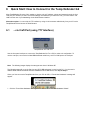
6.1
...via Craft Port (using TTY Interface)
TempDefender G2 Craft Port
Use the front panel craft port to connect the TempDefender G2 IT to a PC for onsite unit configuration. To
use the craft port, connect the included DB9 download cable from your PC's COM port to the craft port.
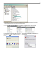
Note: The following images display the setup process done in Windows XP.
The following steps will occur the first time any DPS USB equipment is used on this PC. If you've used a
different DPS USB device before and have installed the DPS USB drivers, then skip to Step 9.
When you first connect the TempDefender G2 to your PC via USB, a "Found New Hardware" message will
appear:
1. Click the "Found New Hardware" message/icon to launch the "Found New Hardware Wizard".
10
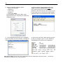
2. Select "Install from a list or specific location (Advanced)"
3. Click "Next >"
4. Select "Search for the best driver in these locations."
5. Insert TempDefender G2 Resource Disc (CD) into your PC.
6. Click "Browse"
11
7. Select the "Driver" folder of your TempDefender G2 Resource Disc Disc (CD) and click "OK"
The following message will confirm installation of a new "USB Communications Port"
8. Click "Finish" to close the Wizard.
Now that the driver has been installed, a new COM port is being emulated on your PC. Before using
hyperterminal, you must confirm the identity of that new COM port (COM1, COM2, COM3...) in the Windows
Device Manager.
12
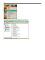
9. Right-click the "My Computer" icon on your desktop, then click "Manage"
10.Click "Device Manager" in the left pane.
13
11.Expand the "Ports (COM & LPT)" section in the right pane. Look for "USB Communications Port (COMx)".
Note the number of the COM port ("COM3" in the example above).
12.Click on the Start menu > select Programs > Accessories > Communications > HyperTerminal.
13. At the Connection Description screen, enter a name
for this connection. You may also select an icon. The
name and icon do not affect your ability to connect to
the unit.
14. At the Connect To screen, use the drop-down
menu to select the COM port you found earlier in the
Device Manager.
14
15. Select the following COM port options:
• Bits per second: 9600
• Data bits: 8
• Parity: None
• Stop bits: 1
• Flow control: None
Once connected, you will see a blank, white
HyperTerminal screen. Press Enter to activate the
configuration menu.
16. When prompted, enter the default user name
admin and password dpstelecom. NOTE: If you
don't receive a prompt for your user name and
password, check the Com port you are using on your
PC and make sure you are using the cable provided.
Additional cables can be ordered from DPS Telecom.
17. The TempDefender G2's main menu will appear.
Type C for C)onfig, then E for E)thernet. Configure the
unit's IP address, subnet mask, and default gateway.
18. ESC to the main menu. When asked if you'd like
to save your changes, type Y for Y)es. Reboot the
TempDefender G2 to save its new configuration.
Now you're ready to do the rest of your configuration via LAN. Please refer to the next section "...via LAN" for
instructions on setting up your LAN connection.
15
6.2
...via LAN
TempDefender G2 Ethernet Port
To connect to the TempDefender G2 via LAN, all you need is the unit's IP address (Default IP address is
192.168.1.100).
If you DON'T have LAN, but DO have physical access to the TempDefender G2, connect using a LAN
crossover cable. NOTE: Newer PCs should be able to use a standard straight-through LAN cable and handle the
crossover for you. To do this, you will temporarily change your PC's IP address and subnet mask to match the
TempDefender G2's factory default IP settings. Follow these steps:
1.
Get a LAN crossover cable and plug it directly into the TempDefender G2's LAN port.
2.
Look up your PC's current IP address and subnet mask, and write this information down.
3.
Reset your PC's IP address to 192.168.1.200. Contact your IT department if you are unsure how to do this.
4.
Reset your PC's subnet mask to 255.255.0.0. You may have to reboot your PC to apply your changes.
5.
Once the IP address and subnet mask of your computer coincide with the unit, you can access the unit via
a Telnet session or via Web browser by using the unit's default IP address of 192.168.1.100.
6.
Provision the TempDefender G2 with the appropriate information, then change your computer's IP
address and subnet mask back to their original settings.
Now you're ready to do the rest of your configuration via LAN. Plug your LAN cable into the TempDefender G2 and
see "Logging On to the TempDefender G2" to continue databasing using the Web Browser.
16
7
TTY Interface
The TTY interface is the TempDefender G2's built-in interface for basic configuration. From the TTY interface, you
can:
Edit the IPA, subnet, and gateway
Set DCP info for T/Mon polling
Configure primary port
Ping other devices on the network
Set unit back to factory defaults
Debug and troubleshoot
For more advanced configuration tools, please use the Web Browser Interface.
For Telnet, connect to the IP address at port 2002 to access the configuration menus after initial LAN/WAN setup.
Telnet sessions are established at port 2002, not the standard Telnet port as an added security measure.
If you're using Windows 7, then you'll need to install telnet before you can use the TTY interface. To install telnet,
open up your command line (type "cmd" into the search bar in the Start Menu). Select cmd.exe to run the
command line.
From the command line, type in pkgmgr /iu:"TelnetClient" then press enter. When the command prompt
appears again, the installation is complete.
Menu Shortcut Keys
The letters before or enclosed in parentheses () are menu shortcut keys. Press the shortcut key to access that
option. Pressing the ESC key will always bring you back to the previous level. Entries are not case sensitive.
17
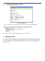
7.1
Configure Serial Port via TTY
Serial port configuration
1. To enter configuration setting for the Serial Port, login to the TTY interface and press C)onfig > s(E)rial.
2. Press the hot keys to toggle through the following options. (* Indicates default settings:)
NOTE: Default settings may not reflect the primary interface that shipped in the unit.
Port Type: 232*, 485
Baud: 9600*, 57600, 19200, 9600, 4800, 2400, 1200
Parity: None*, even, odd
Stop bits: 1*, 2
3. Set the RTS head / tail (Carrier time) Suggested settings are: 0,0 if using RS232.
8
Quick Turn Up
The next sections of this manual will walk you through some of the most common tasks for using the TempDefender
G2. You will learn how to send email notifications, and send SNMP traps to your alarm master - all using the Web
browser. For details on entering your settings into each Web browser menu, the section "Provisioning Menu Field
Descriptions" section.
18
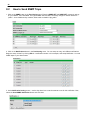
8.1
How to Send Email Notifications
1. Click on the Notifications button in the Provisioning menu. You can setup as many as 8 different notifications.
Begin the setup "wizard" by clicking Edit for a notification number. In this example, we'll setup Notification 1 to send
emails.
2. At the Notification Setting screen, use the drop down box to set what events to use for this notification. Now,
select the Send Email Notification button and click Save and Next.
3. At the Email Notification screen, you'll enter your email server settings. Enter the IP address or Host Name of
your email server. Enter the Port Number (usually 25) and the "To" Email Address of the technician that will
receive these emails. If authentication is required, chose the type and fill in the necessary fields. Click Next.
19
4. At the Schedule screen, you'll select the exact days/times you want to receive email notifications. You can set
2 schedules per notification. For example, you may want to receive notifications at certain times during the week,
and at different hours on the weekend. Use the check boxes to select the days of the week, and select the time
from the drop down menus. Click Finish. To try a test notification, click the Test button (See next step.)
5. If you chose to test the email notification you've just setup, you will prompted with a pop up . Click OK to send a
test email alarm notification. Confirm all your settings by checking your email to see if you've received it. NOTE:
This test only means that your notification settings are correct, but you still need to assign the notification to an
alarm point. See the next step.
6. Now you will associate this notification to an alarm (system, base, analog, etc.) You have 8 notification devices
available to use. In the image below, you might assign Notification Device 1 to Alarm 1. This means that you
would receive an email notification when an alarm for Alarm 1 (SERVER ROOM) occurs.
20
8.2
How to Send SNMP Traps
1. Click on the SNMP button in the Provisioning menu. Enter the SNMP GET and SNMP SET community strings
for your network, then click Save. The typical SNMP SET and GET community strings for network devices is
"public". As an added security measure, we've made our default "dps_public".
2. Click on the Notifications button in the Provisioning menu. You can setup as many as 8 different notifications.
Begin the setup "wizard" by clicking Edit for a notification number. In this example, we'll setup Notification 1 to send
SNMP traps to your alarm master.
3. At the Notification Setting screen, use the drop down box to set what events to use for this notification. Now,
select the Send SNMP Notification button and click Next.
21
4. At the SNMP Notification screen, you'll enter your network's SNMP settings. Enter the IP address of your
SNMP Trap Server. Enter the Trap Port Number (usually 162) and the Trap Community password. Click Save
and Next.
5. At the Schedule screen, you'll select the exact days/times you want to receive SNMP notifications. You can
set 2 schedules per notification. For example, you may want to receive notifications at certain times during the
week, and at different hours on the weekend. Use the check boxes to select the days of the week, and select the
time from the drop down menus. Click Save and Finish. To try a test notification, click the Test button (See next
step.)
6. If you chose to test the email notification you've just setup, you will prompted with a pop up . Click OK to send a
test SNMP alarm notification. Confirm all your settings by checking your alarm master to see if the SNMP trap was
received.
NOTE: This test only means that your notification settings are correct, but you still need to assign the notification to
an alarm point. See Step 6 in "How to Send Email Notifications" for more detail.
22
9
Provisioning Menu Field Descriptions
TempDefender G2 configuration is performed from the Provisioning menus, the menu options in green on the leftside of the web interface. The following pages provide a brief description of the options available in each menu.
Saving Configuration Changes to the TempDefender G2:
At the bottom of each screen you access from the Provisioning Menu, you will see a Save button. Clicking Save
will cache your changes locally. The web interface will then prompt you to either Write your changes to the unit or
Reboot the unit for changes to take effect in the top-left corner of your browser. The relevant options will be
highlighted in the Device Access options.
Note: If the unit prompts you to both Write changes to the unit and Reboot, you will Write your changes first.
Rebooting without writing to the unit (if a Write is required) will cause you to lose your configuration changes.
Status messages on the TempDefender G2 Device Access menu, inform you how to implement your changes
The control menu highlights items that must be completed for your changes to tak e effect
23
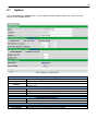
9.1
System
From the Provisioning > System menu, you will configure and edit the global system, call, T/Mon and control
settings for the TempDefender G2.
The Provisioning > System menu
Name
Location
Contact
DCP Unit ID
DCP Unit Protocol
DCP over LAN port
LAN Protocol
Modbus Unit ID
Modbus Port
Get History
Erase History
Global System Settings
A name for this TempDefender G2 unit. {Optional field)
The location of this TempDefender G2 unit. {Optional field)
Contact telephone number for the person responsible for this TempDefender G2 unit.
{Optional field)
DCP Responder Settings (For use with T/Mon)
User-definable ID number for the target unit (DCP Address)
Drop-down menu of available protocols for use with DCP Address
Enter the DCP port for the target unit (UDP/TCP port)
Drop-down menu of available protocols for use over LAN
Modbus Responder Settings
User-definable ID number (Modbus Address)
Enter the Modbus port number
Sensors History
Download a log of all configured analog and sensor values.
Erase the log of all configured analog and sensor values.
24
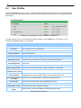
9.2
User Profiles
Clicking User Profiles gives you access to modify the default username and password, and to edit the administrator
profile and create up to 9 additional unique user profiles, each with different access rights to the TempDefender G2's
web interface.
Configure access privileges for users in the User Profile screen
To create or edit any of the 10 user profiles (including the Admin), click the Edit button. From there, you can
change all configurable settings for a user profile.
User Profile
Suspend this Profile
If this box is checked, the profile will not be able to access the TempDefender G2.
Username
Enter a username or a user description
Password
Enter a unique user password Note: All passwords are AES 128 encrypted.
Confirm Password
Re-enter the password.
Access Rights
Check all
Edit logon profiles
Enables all Access Rights
Enables the user to add/modify user profiles and password information.
Write Config (change
unit configuration)
Enables the user to change the unit config by accessing the Write feature in the
control menu.
View monitor pages
Allows the user to access Monitor menu options.
Send relay commands Allows the user to send commands to operate the device's control relays.
TTY access (access via Grants the user access to the unit via TTY interface (via craft or telnet).
Craft port or via Telnet)
Initialize config to
factory defaults
Allows the user to use the Initialize option in the Device Access menu, resetting the
TempDefender G2 to factory default settings. All user settings will be lost.
Upload new firmware, Allows the user to upload firmware or backed-up configuration files.
or config
Get audit log
Allows the user to access the Audit Log (Get Log command).
Purge (delete) audit log Allows the user to deletes the existing audit log.
Get (backup) config
Backs-up all user profile configuration settings.
Get and delete analog
Allows the user to access and delete the analog and sensor history.
history
User profile field descriptions
25
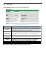
9.3
Ethernet
The Edit > Ethernet menu allows you to define and configure Ethernet settings.
The Provisioning > Ethernet menu
MAC Address
Host Name
Enable DHCP
Unit IP
Subnet Mask
Gateway
DNS Server 1
DNS Server 2
Ethernet Settings
Hardware address of the TempDefender G2. (Not editable - For reference only.)
Used only for web browsing. Example: If you don't want to remember this TempDefender
G2's IP address, you can type in a name is this field, such as "MyTempDefender G2".
Once you save and reboot the unit, you can now browse to it locally by simply typing in
"MyTempDefender G2" in the address bar. (no "http://" needed).
Used to turn on Dynamic Host Connection Protocol. NOT recommended, because the
unit is assigned an IP address from your DHCP server. The IP you've already assigned to
the unit becomes inactive. Using DHCP means the unit will NOT operate in a T/Mon
environment.
IP address of the TempDefender G2.
A road sign to the TempDefender G2, telling it whether your packets should stay on your
local network or be forwarded somewhere else on a wide-area network.
An important parameter if you are connected to a wide-area network. It tells the
TempDefender G2 which machine is the gateway out of your local network. Set to
255.255.255.255 if not using. Contact your network administrator for this info.
Primary IP address of the domain name server. Set to 255.255.255.255 if not using.
Secondary IP address of the domain name server. Set to 255.255.255.255 is not using.
Note: DNS Server settings are required if a hostname is being used for ping targets.
26
9.4
Serial Port
The Provisioning > Serial Port menu allows you to change settings depending on the port type of your
TempDefender G2. From this menu, you can select a mode of operation and enable reach-through serial port
functionality.
The Provisioning > Serial Ports menu
Location
A reminder that your primary serial port is located on the back of the TempDefender G2
chassis.
Port Configuration
Select the serial port for your build of the TempDefender G2.
Port Type
Choose from 232, 485...
Baud, Parity, and Stop Bits Select the appropriate settings from the drop-down menu.
Only used if your TempDefender G2 was built with a 202
RTS Head
modem. The most commonly used value is 30.
Only used if your TempDefender G2 was built with a 202
RTS Tail
modem. The most commonly used value is 10.
Reach-Through
Checking this box enables the port to be used as a terminal
server. Most commonly used to Telnet through the port over
LAN to a hub, switch, or router. From a command prompt,
Enable Reach-through
type the following (note the spaces between each entry):
telnet [IP address] [port]
Example: telnet 192.168.1.100 3000
Port
Port number used for reach-through to a serial device.
Select TCP or UDP traffic to be passed through to a serial
Type
device.
27
9.5
SNMP
The Provisioning > SNMP menu allows you to define and configure the SNMP settings.
SNMP Menu
Global Settings
Get Community
Community name for SNMP requests.
Set Community
Community name for SNMP SET requests.
Read and Write
Access
This field defines how the TempDefender G2 unit may be accessed via SNMP. This can
be set to the following:
Access Disabled- Restricts all access to unit via SNMP
SNMPv2c only- Allows SNMPv2c access only
SNMPv2c and SNMPv1-Only- Allows SNMPv1 and SNMPv2c access
SNMPv3, SNMPv2c and SNMPv1- Allows SNMPv3, SNMPv2c and SNMPv1 access
Fields in the Provisioning > SNMP settings
28
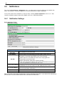
9.6
Notifications
From the initial Provisioning > Notifications menu, you will see which of the 8 notifications are enabled, their
server, and schedule. Click on the Edit link for one of the notifications to begin configuration.
Once you've chosen which notification you want to setup, check the Enable Notification to turn it "on." Then
choose a notification method, either email, SNMP, voice call, or TRIP Dialup (T/Mon).
9.6.1
Notification Settings
Email Notification Fields
Editing Email Notification Settings
Email Notification
SMTP Server IP or
Host Name
Port Number
The IP address of your email server.
The port used by your email server to receive emails, usually set to 25.
Check this box to use SSL encryption. Currently this feature has been tested
with Gmail. To send with Gmail SMTP server, do the following:
SMTP Server IP or Host Name should be set to "smtp.gmail.com"
Use SSL
Port number must be set to 465.
SMTP authentication radio button must be selected.
User name and password (below under "How to Authenticate") are the user
name and password for the Gmail account in use.
Displays the email address (defined in the Edit menu > System) that the
"From" E-mail Address
TempDefender G2 will send emails from. Not editable from this screen.
The email address of the person responsible for this TempDefender G2, who
"To" E-mail Address
will receive email alarm notifications.
User Name
User name for the Gmail account being used.
Password
Password for the Gmail account being used.
Note: If you want to send authenticated emails, click the appropriate radio button. If you enable POP authentication,
you will have to enter the relevant authentication information the fields below.
29
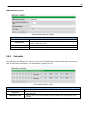
SNMP Notification Fields
Editing SNMP notification settings
SNMP Trap Server IP
Trap Port No.
Trap Community
Trap Type
9.6.2
SNMP Notification
The SNMP trap manager's IP address.
The SNMP port (UDP port) set by the SNMP trap manager to receive
traps, usually set to 162.
Community name for SNMP TRAP requests.
Indicate whether you would like to send SNMP v1, v2c or v3 traps.
Schedule
The notifications scheduling menu is where you will tell the TempDefender G2 exactly which days and times you
want to receive alarm notifications. You set 2 different schedules for each.
The Schedule creation screen
Days of the week
Any Time
Notification Time
Notification Scheduling
From either Schedule 1 or 2, check which days you want to receive notifications.
Select this is if you want to receive alarm notifications at any time for the day(s)
you've selected.
Tells the unit to only send notifications during certain hours on the day(s) you've
selected.
30
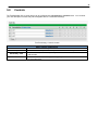
9.7
Alarms
Discrete alarms are configured from the Provisioning > Alarms menu. Descriptions for the alarm points, polarity
(normal or reversed) and notification type(s) are defined from this menu. You also have the option to use Basic or
Advanced configuration methods, explained in this section.
The Provisioning > Alarms menu
ID
Description
Rev (Reverse)
Notification Devices
On Set
On Clear
Qual. Time (Qualification
Time)
Qual. Type (Qualification
Type)
Basic Alarm Configuration
Alarm ID number.
User-definable description for the discrete alarm point.
Reverse: Check this box to reverse the polarity of the alarm point. Leaving this option
un-checked means a normally open contact closure is an alarm. When polarity is
reversed, a normally closed alarm point is clear when closed.
Check which notification device(s), 1 through 8, you want to send alarm notifications
for that alarm point.
Advanced Alarm Configuration (Advanced>>)
User-definable description (condition) that will appear for the discrete alarm input on
Set. Example: "Alarm".
User-definable description (condition) that will appear for the discrete alarm input on
Clear: "Example: "Alarm Cleared".
The length of time that must pass, without interruption, in order for the condition to be
considered an Alarm or a Clear.
Allows you to choose whether you want to apply the Qualification Time to the alarm
Set, Clear, or Both.
31
9.8
Controls
The TempDefender G2's 3 control relays can be configured in the Provisioning > Controls menu. You can enter
your own description for these relays and designate them to a notification device(s).
The Provisioning > Controls screen
ID
Description
Momentary Time
Notification Devices
Basic Controls Configuration
ID number for the control relay.
User-definable description for the TempDefender G2's control relay.
Control on time (in milliseconds) when you execute the MOM command. Max limit of
600 seconds.
Check which notification device(s), 1 through 8, you want to send alarm notifications
for the control relay.
32
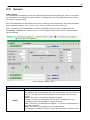
9.9
User Analogs
The TempDefender G2's sixteen multi-purpose analog inputs measure continuous ranges of voltage or current.
Analog alarms are typically used to monitor battery voltage, charging current, temperature, humidity, wind speed, or
other continuously changing conditions. To configure a user analog, simply fill in your description, thresholds, and
other fields listed in the table below, then click Save.
The Provisioning > User Analogs menu
Note: Analog channels 7 and 8 are for internal voltage monitoring (On a single power input build, channel 7 is
unused.)
User Analogs
Default monitoring to Checking this box sets the default view in the Monitor>User Analogs menu to the gauge
gauge view
view.
Enab (Enable)
Checking the box in the Enab column enables monitoring of the analog channel.
Description
User-definable description for the analog channel
Checking the reverse button changes negative values to positive, and positive values to
Rev
negative.
Check which notification device(s), 1 through 8, you want to send alarm notifications for
Notifications
this analog input.
Details
Record Freq
The frequency with which the NetGuardian will record the analog reading
The additional qualifying value the NetGuardian requires above/below your alarm thresholds
Deadband
in order to set an alarm.
Units
The unit(s) of measurement reported by a connected analog input.
Low ref and High Ref The low and high values for scaling voltage to your display units.
MjU (Major Under)
MnU (Minor Under) Threshold settings that, when crossed, will prompt the NetGuardian to set an alarm.
MnO (Minor Over) Recorded values less than an under value or greater than an over value will cause alarms.
MjO (Major Over)
Enable
Checking this box enables Push-to-Talk feature for this analog.
Discrete Input
Assign the alarm point associated with this analog.
Length of time, in milliseconds, that an alarm point must be set before before an analog
Qual. Time (ms)
can post.
Select the type of analog gauge represented in the Monitor>User Analogs>Gauge View
Analog Gauge Type
menu
33
9.10
Sensors
D-Wire Sensors
The TempDefender G2 supports up to 32 daisy-chained D-Wire sensors via its D-Wire input. Sensors connected to
the TempDefender G2 will appear on the web interface. The background color of the ROM field informs the user of
the sensor's configuration state.
Also the TempDefender G2's first D-Wire sensor used to monitor the internal temperature. The internal temperature
sensor measures a range of -40° F to 180° F (-40° C to 82.2° C) within an accuracy of about ± 2°.
Basic configuration for the TempDefender G2's D-Wire temperature sensors can be accomplished from the
Provisioning > Sensors menu. From this screen, you can configure D-Wire sensors, select notification devices,
and set thresholds.
The Provisioning > Sensors menu
ID
ROM ID
Basic Sensor Configuration
Sensor ID number.
The ID number found on the sticker of the temperature sensor node. Your
TempDefender G2 will automatically detect the sensor ID when you plug a sensor into
the unit. The color of the sensor ID field will tell you the status of the connected
sensor.
Green - The sensor is connected and properly configured.
Yellow - The sensor is connected but has not yet been configured (fill in your
configuration fields and click Save to configure the sensor).
Red - The sensor is not detected and configured (i.e. a previous configured sensor is
no longer connected).
Blue - The sensor is not supported by the TempDefender G2.
To reconfigure or disable the Sensor ID, simply delete any data in this field and click
34
Description
Parse
Notification Devices
Record Freq
Deadband
Qual Time (Qualification
Time)
Qual. Type (Qualification
Type)
Thresholds
Analog Gauge Type
Save.
The unit will refresh the sensor ID on that channel.
User-definable description for the sensor channel.
Checks to see if the Description field contains a valid equation.
Check which notification device(s), 1 through 8, you want to send alarm notifications
for that alarm point.
Advanced Sensor Configuration (Details>>)
The amount of time, in minutes (min) or seconds (s), between each recorded sensor
value.
The amount (in native units) that the channel needs to go above or below a threshold
in order to cause an alarm.
The length of time that must pass, without interruption, in order for the condition to be
considered an Alarm or a Clear.
Allows you to choose whether you want to apply the Qualification Time to the alarm
Set, Clear, or Both.
These settings are set to indicate the severity of the alarm depending on which
threshold values have been passed. Enter values for Major Under (MjU), Minor Under
(MnU), Minor Over (MnO), and Major Over (MjO).
Select the color-coded gauge that best represents your data. Selecting None will
disable the analog gauge and only a numerical representation of the value will be
displayed under Monitor > Sensors.
Note: Before plugging in any additional D-Wire Sensors, set up the internal sensor.
Script Sensors
A Script Sensor can be setup by entering a script type in the sensor ID field. The following types are currently
supported:
~count - The equation will be evaluated continuously. If the evaluation changes at any point, the sensor's value
increases by an increment of 1. This mode can be useful for counting the number of times a discrete input
toggles.
Evaluation Sensor; every tenth of a minute (6 seconds).
~evalMt - The equation is evaluated every 6 seconds and its result becomes the sensor's value.
Evaluation Sensor; every minute.
~evalMn - The equation is evaluated every 60 seconds and its result becomes the sensor's value.
Interval counter.
Interval Sensor
~intCnt - Sensor value will increment when the associated input's pulse length (high or low) is within a set
interval. Example: D5 V1 0 0 0 > V6 0 0 0 0 < means the sensor value will increment when a 1ms to 60ms pulse
is detected on Discrete Input 5. This is useful for frequency detection/tracking.
A Script Sensor is configured to evaluate Reverse Polish Notation equations. A data token in an equation can
represent a discrete alarm, analog reading, sensor reading, relay status, system alarm status, or a constant value.
The format for a token in an equation must be a data type followed by an index (for example: Discrete Input 1 in an
equation would be represented as "d1", Analog Channel 3 would be "a3", etc.). Each token is typically followed by
another token or an operator. The equations are entered in the description field for the Script Sensor.
35
Valid data types:
d Discrete Input
a Analog Channel
r Relay State
n Sensor
v Positive Integer Constant
s System Alarm
Valid operations:
+ Addition
- Subtraction
* Multiplication
/ Division1
> Greater than
< Less than
| Conditional Halt2
1. Division is NOT executed if the denominator's absolute value is less than 1!
2. An equation is evaluated until it reaches the Conditional Halt. If the running value at that point is zero, then the
evaluation stops, otherwise the evaluation continues as a new equation.
How equations are evaluated:
Calculations are performed from left-to-right until the end of the equation is reached. As the equation is parsed,
each token's value is pushed onto a stack until an operator is found. When an operator is found, the previous 2
values are popped from the stack and are used to perform the operation (the first item popped is the SECOND
operand). The result of the operation is then pushed onto the stack. This repeats until the end of the equation is
reached. An equation is valid only if there is exactly ONE item left in the stack when the end of the equation is
reached.
Example of how an equation is evaluated:
Equation: a8 a5 a6 + * a4 Input
a8
a5
Operation
Push value
Push value
Stack
Comment
a8
a5
a8
a6
Push value
a6
a5
a8
+
Add
(a5+a6)
Pop a6 and a5, add them, push result to stack
a8
*
Multiply
a8*(a5+a6)
Pop (a5+a6) and a8, multiply them, push result to stack
a4
Push value
a4
a8*(a5+a6)
Subtract a8*(a5+a6) - a4 Pop a4 and a8*(a5+a6), subtract them, push result to stack
In this example, after the subtraction there is only ONE item left in the stack (which is the result of all of the
previous computations), mak ing this a valid equation.
36
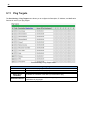
9.11
Ping Targets
The Provisioning > Ping Targets menu allows you to configure the Description, IP Address, and Notification
Devices for each of your ping targets.
The Provisioning > Ping Targets menu
ID
Enab
Description
Server (IP or
Hostname)
Notification Devices
Provisioning Ping Targets
ID number for the ping target.
Check this box to enable the ping target.
User-definable description for the ping target.
IP address or hostname of the device you would like to ping.
Check which notification device(s), 1 through 8, you want to send alarm
notifications for ping target.
37
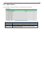
9.12
System Alarms
See "Display Mapping" in the Reference Section for a complete description of system alarms.
The Provisioning > System Alarms menu
Editing System Alarms
The system alarm point number
Non-editable description for this System (housekeeping) Alarm.
Check this box to choose to silence this alarm.
Check which notification device(s), 1 through 8, you want to send alarm
Notification Devices
notifications for that alarm point.
Pnt (Point)
Description
Silence
38
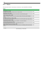
9.13
Timers
Enter the amount of time in seconds (sec) or minutes (m), in each value field and click Save.
The Provisioning > Timers menu
39
9.14
Date and Time
The Provisioning > Date and Time menu
Unit Time
Set today's date.
Set the current time.
Automatic Time Adjustment (NTP)
Enable NTP
Check this box to enable Network Time Protocol.
Enter the NTP server's IP address or host name, then click Sync.
NTP Server Address or Host Name Example: us.pool.ntp.org. Note: Make sure to configure DNS before using
host name instead of IP address.
Time Zone
Select your time zone from the drop-down menu.
Adjust Clock for Daylight Savings Time (DST)
Enable DST
Check this box to have the TempDefender G2 observe Daylight Savings.
Start Day
Select the month, weekday, and time when Daylight Savings will begin.
End Day
Select the month, weekday, and time when Daylight Savings will end.
Date
Time
40
10 Monitoring via the Web Browser
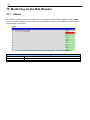
10.1
Alarms
This selection provides the status of the base alarms by indicating if an alarm has been triggered. Under the State
column, the status will appear in red if an alarm has been activated. The status will be displayed in green when the
alarm condition is not present.
Click on Alarms in the Monitor menu to see if any base alarms (1-8) have been triggered.
ID
Description
State
Basic Alarm Monitoring
Alarm ID number.
User-definable description for the discrete alarm point.
The current state of the alarm. (Clear or Alarm)
41
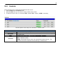
10.2
Controls
Use the following rules to operate the TempDefender G2's control:
1. Select Controls from the Monitor menu.
2. Under the State field, you can see the current condition of the control.
3. To issue the control, click on a command (OPR - operate, RLS - release, or MOM - momentary)
View and operate control relays from the Monitor > Controls menu
ID
Description
State
Command
Control Relay Operation
ID number for the control relay.
Description for the TempDefender G2's control relay defined in the Provisioning >
Controls menu.
Status of the control relay. Can either be Released or Latched.
OPR - Latch the relay.
RLS - Release the relay.
MOM - Momentarily latch the relay, then automatically release the relay. The
duration of the latch is defined in the Provisioning > Controls menu.
42
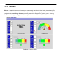
10.3
Sensors
This selection provides the status of the system's analog channels by indicating if an alarm has been triggered. The
Monitor > Sensors screen provides a description of each analog channel, the current reading, the units being read,
and alarm conditions (major under, minor under, major over, minor over) according to your temperature settings. If
configured under Provisioning > Sensors, your analog values will be displayed as a graphical gauge. Selecting
Table View will display a non-graphical interface of your values.
The Monitor > Sensors menu
43
10.4
User Analogs
On the Monitor > User Analogs menu, you can monitor all analog inputs. The most recent
measurement will be shown, and any alarm thresholds crossed will be shown in shown in either orange
for minor alarms or red for major alarms.
Fig. 12.5 Current status of all analog inputs in the Monitor > User Analogs in Table View.
Fig. 12.6 Current status of all analog inputs in the Monitor > User Analogs in Gauge View.
Note: The analog gauges do not account for the user definable Deadband. This may result in an alarm threshold to
appear crossed in the gauge animation when the point has not set or cleared.
44
10.5
Ping Targets
Ping Targets can be viewed by going to Monitor > Ping Targets. Here you can view the state (either Clear or
Alarm) for each of your configured Ping Targets.
View the status of Ping Targets from the Monitor > Ping Targets menu.
45
10.6
System Alarms
System alarms are not-editable, housekeeping alarms that are programmed into TempDefender G2. The Monitor >
System Alarms screen provides the status of the system alarms by indicating if an alarm has been triggered. Under
the State column, the status will appear in red if an alarm has been activated. The status will be displayed in green
when the alarm condition is not present.
See "Display Mapping" in the Reference Section for a complete description of system alarms.
View the status of System Alarms from the Monitor > System Alarms menu.
46
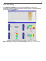
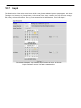
10.7
Graph
The Graph section of the monitor menu lets you build a graph of past analog and sensor measurements, which gives
you a visual indication of data over time and points out trending values. To create your Graph, specify the Channel
(Analogs 1-8 or Sensors 1-32), Group Interval (1-120 minutes, hours, days, or weeks), the Group Function (Average,
Min, Max), and Start & End Times. Once you have entered all of the desired values, click "Build Graph."
Provision the Channels, Group Interval, Group Function and more - all from the
Graph Parameters section of the web browser interface.
47
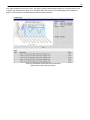
Your graph will appear on the next screen. This graph is Adobe Flash-based and allows you to mouse over the lines
to quickly view measurements (date, time, and value) within their context of the overall graphing trend. Below the
graph is a full textual list of all indexed points with their dates and values.
Specify your parameter values and build an interactive
graph based on the alarm point history.
48
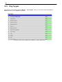
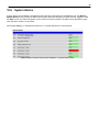
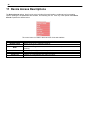
11 Device Access Descriptions
The Device Access options, listed in pink on the left side of the web interface, provide options for generating
reports, updating the TempDefender G2's firmware, and rebooting the unit. Click any of the options under Device
Access to perform the desired action.
The control menu is located in the bottom left of the web interface
Device Access Option
Backup Config
Read
Write
Initialize
Get Log
Purge Log
Reboot
Description
Backs up the units configuration settings
Reads a configuration file from the unit
Commits all changes made in the web interface to the TempDefender G2's non-volatile
memory
Sets the unit's configuration to factory default values
Opens the TempDefender G2's event log in Notepad (or another plain text editor).
Deletes the TempDefender G2's event log history.
Reboots the TempDefender G2.
49
12 Backup Configuration
With the TempDefender G2 you can backup your current configuration from the Web Interface. These configuration
files can then be uploaded later, or uploaded to other TempDefender G2 units.
The Back up Config tab is located in the Device Access menu shown above.
How to backup your current configuration:
1. Click the Backup Config tab from the Device Access menu.
2. When prompted by your web browser, download the file to your desktop or other location on your computer.
3. Now your configuration should be saved. If you need to upload a configuration, follow the steps below.
To upload your configuration file, click on Upload on the top right corner of the web interface
How to upload a saved configuration:
1. Click the upload button at the top right corner of the Welcome screen.
2. Click the Browse... button
3. Browse to the location of the .bin file from the steps above.
4. Select that .bin file and press the Upload button.
5. You should now have the same configuration settings loaded from when you saved the .bin file above.
50
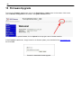
13 Firmware Upgrade
To access the Firmware Load screen, click on the Provisioning > System menu. At the bottom of this screen,
click the Restore Configuration link located in the System Controls section.
To upload firmware, click on Upload on the top right corner of the web interface
At the Firmware Load screen, simply browse for the firmware update you've downloaded from www.dpstele.com
and click Load.
Browse for downloaded firmware upgrade
51
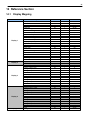
14 Reference Section
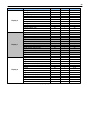
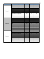
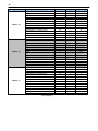
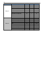
14.1
Display Mapping
Display 1
Display 2
Display 3
Display 4
Display 5
Description
Discrete Alarms 1-8
Undefined
Controls 1-3
Undefined
Default Configuration
DIP Switch Config
MAC Address Not Set
IP Address Not Set
LAN Hardware Error
SNMP Processing Error
SNMP community error
LAN TX packet drop
Notification Failed 1-8
NTP failed
Timed Tick
Serial 1 RcvQ full
Dynamic memory full
Unit reset
DCP poller inactive
Reserved
Modbus poller inactive
Reserved
Ping Alarms 1-32
Undefined
Analog 1 Minor Under
Analog 1 Minor Over
Analog 1 Major Under
Analog 1 Major Over
Control
Value
Analog 2 Minor Under
Analog 2 Minor Over
Analog 2 Major Under
Analog 2 Major Over
Control
Value
Analog 3 Minor Under
Analog 3 Minor Over
Analog 3 Major Under
Analog 3 Major Over
Control
Value
Analog 4 Minor Under
Analog 4 Minor Over
Analog 4 Major Under
Analog 4 Major Over
Control
Value
Analog 5 Minor Under
Port
99
99
99
99
99
99
99
99
99
99
99
99
99
99
99
99
99
99
99
99
99
99
99
99
99
99
99
99
99
99
99
99
99
99
99
99
99
99
99
99
99
99
99
99
99
99
99
99
99
Address
1
1
1
1
1
1
1
1
1
1
1
1
1
1
1
1
1
1
1
1
1
1
1
1
1
1
1
1
1
1
1
1
1
1
1
1
1
1
1
1
1
1
1
1
1
1
1
1
1
Point
1-8
9-16
17-19
22-32
33
34
35
36
37
38
39
40
41-48
49
50
51
52
53
54
55
56
57-64
1-32
33-64
1
2
3
4
9-16
17-32
33
34
35
36
41-48
49-64
1
2
3
4
9-16
17-32
33
34
35
36
41-48
49-64
1
52
Analog 5 Minor Over
Analog 5 Major Under
Analog 5 Major Over
Control
Value
Analog 6 Minor Under
Analog 6 Minor Over
Analog 6 Major Under
Analog 6 Major Over
Control
Value
99
99
99
99
99
99
99
99
99
99
99
Display Mapping
1
1
1
1
1
1
1
1
1
1
1
2
3
4
9-16
17-32
33
34
35
36
41-48
49-64
53
Display 6
Display 7
Display 8
Description
Analog 7 Minor Under
Analog 7 Minor Over
Analog 7 Major Under
Analog 7 Major Over
Control
Value
Analog 8 Minor Under
Analog 8 Minor Over
Analog 8 Major Under
Analog 8 Major Over
Control
Value
Digital sensor 1 Minor Under
Digital sensor 1 Minor Over
Digital sensor 1 Major Under
Digital sensor 1 Major Over
Digital sensor 1 Sensor not detected
Control
Value
Digital sensor 2 Minor Under
Digital sensor 2 Minor Over
Digital sensor 2 Major Under
Digital sensor 2 Major Over
Digital sensor 2 Sensor not detected
Control
Value
Digital Sensor 3 - Minor Under
Digital Sensor 3 - Minor Over
Digital Sensor 3 - Major Under
Digital Sensor 3 - Major Over
Digital Sensor3 Sensor Not Detected
Control
Value
Digital Sensor 4 - Minor Under
Digital Sensor 4 - Minor Over
Digital Sensor 4 - Major Under
Digital Sensor 4 - Major Over
Digital Sensor 4 Sensor Not Detected
Control
Value
Display Mapping
Port
99
99
99
99
99
99
99
99
99
99
99
99
99
99
99
99
99
99
99
99
99
99
99
99
99
99
99
99
99
99
99
99
99
99
99
99
99
99
99
99
Address
1
1
1
1
1
1
1
1
1
1
1
1
1
1
1
1
1
1
1
1
1
1
1
1
1
1
1
1
1
1
1
1
1
1
1
1
1
1
1
1
Point
1
2
3
4
9-16
17-32
33
34
35
36
41-48
49-64
1
2
3
4
5
9-16
17-32
33
34
35
36
37
41-48
49-64
1
2
3
4
5
9-16
17-32
33
34
35
36
37
41-48
49-64
54
Display 9
Display 10
Display 11
Description
Digital Sensor 5 - Minor Under
Digital Sensor 5 - Minor Over
Digital Sensor 5 - Major Under
Digital Sensor 5 - Major Over
Digital Sensor 5 - Not Detected
Control
Value
Digital Sensor 6 - Minor Under
Digital Sensor 6 - Minor Over
Digital Sensor 6 - Major Under
Digital Sensor 6 - Major Over
Digital Sensor 6 - Not Detected
Control
Value
Digital Sensor 7 - Minor Under
Digital Sensor 7 - Minor Over
Digital Sensor 7 - Major Under
Digital Sensor 7 - Major Over
Digital Sensor 7 - Not Detected
Control
Value
Digital Sensor 8 - Minor Under
Digital Sensor 8 - Minor Over
Digital Sensor 8 - Major Under
Digital Sensor 8 - Major Over
Digital Sensor 8 - Not Detected
Control
Value
Digital Sensor 9 - Minor Under
Digital Sensor 9 - Minor Over
Digital Sensor 9 - Major Under
Digital Sensor 9 - Major Over
Digital Sensor 9 - Not Detected
Control
Value
Digital Sensor 10 - Minor Under
Digital Sensor 10 - Minor Over
Digital Sensor 10 - Major Under
Digital Sensor 10 - Major Over
Digital Sensor 10 - Not Detected
Control
Value
Display Mapping
Port
99
99
99
99
99
99
99
99
99
99
99
99
99
99
99
99
99
99
99
99
99
99
99
99
99
99
99
99
99
99
99
99
99
99
99
99
99
99
99
99
99
99
Address
1
1
1
1
1
1
1
1
1
1
1
1
1
1
1
1
1
1
1
1
1
1
1
1
1
1
1
1
1
1
1
1
1
1
1
1
1
1
1
1
1
1
Point
1
2
3
4
5
9-16
17-32
33
34
35
36
37
41-48
49-64
1
2
3
4
5
9-16
17-32
33
34
35
36
37
41-48
49-64
1
2
3
4
5
9-16
17-32
33
34
35
36
37
41-48
49-64
55
Display 12
Display 13
Display 14
Description
Digital Sensor 11 - Minor Under
Digital Sensor 11 - Minor Over
Digital Sensor 11 - Major Under
Digital Sensor 11 - Major Over
Digital Sensor 11 - Not Detected
Control
Value
Digital Sensor 12 - Minor Under
Digital Sensor 12 - Minor Over
Digital Sensor 12 - Major Under
Digital Sensor 12 - Major Over
Digital Sensor 12 - Not Detected
Control
Value
Digital Sensor 13 - Minor Under
Digital Sensor 13 - Minor Over
Digital Sensor 13 - Major Under
Digital Sensor 13 - Major Over
Digital Sensor 13 - Not Detected
Control
Value
Digital Sensor 14 - Minor Under
Digital Sensor 14 - Minor Over
Digital Sensor 14 - Major Under
Digital Sensor 14 - Major Over
Digital Sensor 14 - Not Detected
Control
Value
Digital Sensor 15 - Minor Under
Digital Sensor 15 - Minor Over
Digital Sensor 15 - Major Under
Digital Sensor 15 - Major Over
Digital Sensor 15 - Not Detected
Control
Value
Digital Sensor 16 - Minor Under
Digital Sensor 16 - Minor Over
Digital Sensor 16 - Major Under
Digital Sensor 16 - Major Over
Digital Sensor 16 - Not Detected
Control
Value
Display Mapping
Port
99
99
99
99
99
99
99
99
99
99
99
99
99
99
99
99
99
99
99
99
99
99
99
99
99
99
99
99
99
99
99
99
99
99
99
99
99
99
99
99
99
99
Address
1
1
1
1
1
1
1
1
1
1
1
1
1
1
1
1
1
1
1
1
1
1
1
1
1
1
1
1
1
1
1
1
1
1
1
1
1
1
1
1
1
1
Point
1
2
3
4
5
9-16
17-32
33
34
35
36
37
41-48
49-64
1
2
3
4
5
9-16
17-32
33
34
35
36
37
41-48
49-64
1
2
3
4
5
9-16
17-32
33
34
35
36
37
41-48
49-64
56
Display 15
Display 16
Display 17
Description
Digital Sensor 17 - Minor Under
Digital Sensor 17 - Minor Over
Digital Sensor 17 - Major Under
Digital Sensor 17 - Major Over
Digital Sensor 17 - Not Detected
Control
Value
Digital Sensor 18 - Minor Under
Digital Sensor 18 - Minor Over
Digital Sensor 18 - Major Under
Digital Sensor 18 - Major Over
Digital Sensor 18 - Not Detected
Control
Value
Digital Sensor 19 - Minor Under
Digital Sensor 19 - Minor Over
Digital Sensor 19 - Major Under
Digital Sensor 19 - Major Over
Digital Sensor 19 - Not Detected
Control
Value
Digital Sensor 20 - Minor Under
Digital Sensor 20 - Minor Over
Digital Sensor 20 - Major Under
Digital Sensor 20 - Major Over
Digital Sensor 20 - Not Detected
Control
Value
Digital Sensor 21 - Minor Under
Digital Sensor 21 - Minor Over
Digital Sensor 21 - Major Under
Digital Sensor 21 - Major Over
Digital Sensor 21 - Not Detected
Control
Value
Digital Sensor 22 - Minor Under
Digital Sensor 22 - Minor Over
Digital Sensor 22 - Major Under
Digital Sensor 22 - Major Over
Digital Sensor 22 - Not Detected
Control
Value
Display Mapping
Port
99
99
99
99
99
99
99
99
99
99
99
99
99
99
99
99
99
99
99
99
99
99
99
99
99
99
99
99
99
99
99
99
99
99
99
99
99
99
99
99
99
99
Address
1
1
1
1
1
1
1
1
1
1
1
1
1
1
1
1
1
1
1
1
1
1
1
1
1
1
1
1
1
1
1
1
1
1
1
1
1
1
1
1
1
1
Point
1
2
3
4
5
9-16
17-32
33
34
35
36
37
41-48
49-64
1
2
3
4
5
9-16
17-32
33
34
35
36
37
41-48
49-64
1
2
3
4
5
9-16
17-32
33
34
35
36
37
41-48
49-64
57
Display 18
Display 19
Display 20
Description
Digital Sensor 23 - Minor Under
Digital Sensor 23 - Minor Over
Digital Sensor 23 - Major Under
Digital Sensor 23 - Major Over
Digital Sensor 23 - Not Detected
Control
Value
Digital Sensor 24 - Minor Under
Digital Sensor 24 - Minor Over
Digital Sensor 24 - Major Under
Digital Sensor 24 - Major Over
Digital Sensor 24 - Not Detected
Control
Value
Digital Sensor 25 - Minor Under
Digital Sensor 25 - Minor Over
Digital Sensor 25 - Major Under
Digital Sensor 25 - Major Over
Digital Sensor 25 - Not Detected
Control
Value
Digital Sensor 26 - Minor Under
Digital Sensor 26 - Minor Over
Digital Sensor 26 - Major Under
Digital Sensor 26 - Major Over
Digital Sensor 26 - Not Detected
Control
Value
Digital Sensor 27 - Minor Under
Digital Sensor 27 - Minor Over
Digital Sensor 27 - Major Under
Digital Sensor 27 - Major Over
Digital Sensor 27 - Not Detected
Control
Value
Digital Sensor 28 - Minor Under
Digital Sensor 28 - Minor Over
Digital Sensor 28 - Major Under
Digital Sensor 28 - Major Over
Digital Sensor 28 - Not Detected
Control
Value
Display Mapping
Port
99
99
99
99
99
99
99
99
99
99
99
99
99
99
99
99
99
99
99
99
99
99
99
99
99
99
99
99
99
99
99
99
99
99
99
99
99
99
99
99
99
99
Address
1
1
1
1
1
1
1
1
1
1
1
1
1
1
1
1
1
1
1
1
1
1
1
1
1
1
1
1
1
1
1
1
1
1
1
1
1
1
1
1
1
1
Point
1
2
3
4
5
9-16
17-32
33
34
35
36
37
41-48
49-64
1
2
3
4
5
9-16
17-32
33
34
35
36
37
41-48
49-64
1
2
3
4
5
9-16
17-32
33
34
35
36
37
41-48
49-64
58
Display 21
Display 22
Description
Digital Sensor 29 - Minor Under
Digital Sensor 29 - Minor Over
Digital Sensor 29 - Major Under
Digital Sensor 29 - Major Over
Digital Sensor 29 - Not Detected
Control
Value
Digital Sensor 30 - Minor Under
Digital Sensor 30 - Minor Over
Digital Sensor 30 - Major Under
Digital Sensor 30 - Major Over
Digital Sensor 30 - Not Detected
Control
Value
Digital Sensor 31 - Minor Under
Digital Sensor 31 - Minor Over
Digital Sensor 31 - Major Under
Digital Sensor 31 - Major Over
Digital Sensor 31 - Not Detected
Control
Value
Digital Sensor 32 - Minor Under
Digital Sensor 32 - Minor Over
Digital Sensor 32 - Major Under
Digital Sensor 32 - Major Over
Digital Sensor 32 - Not Detected
Control
Value
Display Mapping
Port
99
99
99
99
99
99
99
99
99
99
99
99
99
99
99
99
99
99
99
99
99
99
99
99
99
99
99
99
Address
1
1
1
1
1
1
1
1
1
1
1
1
1
1
1
1
1
1
1
1
1
1
1
1
1
1
1
1
Point
1
2
3
4
5
9-16
17-32
33
34
35
36
37
41-48
49-64
1
2
3
4
5
9-16
17-32
33
34
35
36
37
41-48
49-64
59
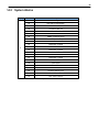
14.2
System Alarms
Display
1
Point
Description
33
Default Configuration
34
DIP Switch Configuration
35
MAC Address Not Set
36
IP Address Not Set
37
LAN hardware error
38
SNMP Process Error
39
SNMP Community Error
40
LAN TX packet drop
41
Notification 1 Failed
42
Notification 2 Failed
43
Notification 3 Failed
44
Notification 4 Failed
45
Notification 5 Failed
46
Notification 6 Failed
47
Notification 7 Failed
48
Notification 8 failed
49
NTP Failed
50
Timed Tick
51
Serial 1 RcvQ full
52
Dynamic Memory Full
53
Unit Reset
54
DCP Poller inactive
System Alarms
60
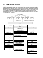
14.3
SNMP Manager Functions
The SNMP Manager allows the user to view alarm status, set date/time, issue controls, and perform a resync. The
display and tables below outline the MIB object identifiers. The table below begins with dpsRTU; however, the MIB
object identifier tree has several levels above it. The full English name is as follows: root.iso.org.dod.internet.private.
enterprises.dps-Inc.dpsAlarmControl.dpsRTU. Therefore, dpsRTU's full object identifier is 1.3.6.1.4.1.2682.1.2. Each
level beyond dpsRTU adds another object identifying number. For example, the object identifier of the Display
portion of the Control Grid is 1.3.6.1.4.1.2682.1.2.3.3 because the object identifier of dpsRTU is 1.3.6.1.4.1.2682.1.4
+ the Control Grid (.3) + the Display (.3).
Tbl. B1 (O.)_OV_Traps
points
_OV_vTraps
(1.3.6.1.4.1.2682.1.2.0)
Tbl. B2 (.1) Identity points
Ident
(1.3.6.1.4.1.2682.1.2.1)
Tbl. B3 (.2) DisplayGrid
points
Manufacturer (.1)
DisplayEntry
(1.3.6.1.4.1.2682.1.2.2.1)
PointSet (.20)
Model (.2)
Port (.1)
PointClr (.21)
Firmware Version (.3)
Address (.2)
SumPSet (.101)
DateTime (.4)
Display (.3)
SumPClr (.102)
ResyncReq (.5)*
DispDesc (.4)*
ComFailed (.103)
* Must be set to "1" to perform the
resync request which will resend TRAPs
for any standing alarm.
PntMap (.5)*
ComRestored (.014)
P0001Set (.10001) through
P0064Set (.10064)
P0001Clr (.20001) through
P0064Clr (.20064)
Tbl. B3 (.3) ControlGrid
points
ControlGrid
(1.3.6.1.4.1.2682.1.2.3)
Tbl. B6 (.6) Analog Channels
Channel Entry
(1.3.6.1.4.1.2682.1.4.6.1)
Tbl. B5 (.5) AlarmEntry
points
Channel Number (.1)
AlarmEntry
(1.3.6.4.1.2682.1.2.5.1)
Port (.1)
Enabled (.2)
Aport (.1)
Address (.2)
Description (.3)
AAddress (.2)
Display (.3)
Value (.4)
ADisplay (.3)
Point (.4)
Thresholds (.5)*
APoint (.4)
Action (.5)
*If Mj, Mn is assumed
APntDesc (.5)*
AState (.6)
* For specific alarm points, see
Table B6
61
14.4
SNMP Granular Trap Packets
The tables below provide a list of the information contained in the SNMP Trap packets sent by the TempDefender
G2.
SNMP Trap managers can use one of two methods to get alarm information:
1. Granular traps (not necessary to define point descriptions for the TempDefender G2) OR
2. The SNMP manager reads the description from the Trap.
UDP Header
Description
1238
Source port
162
Destination port
303
Length
0xBAB0
Checksum
UDP Headers and descriptions
SNMP Header
Description
0
Version
Public
Request
Trap
Request
1.3.6.1.4.1.2682.1.4
Enterprise
126.10.230.181
Agent address
Enterprise Specific
Generic Trap
8001
Specific Trap
617077
Time stamp
1.3.7.1.2.1.1.1.0
Object
TempDefender G2 v1.0K
Value
1.3.6.1.2.1.1.6.0
Object
1-800-622-3314
Value
1.3.6.1.4.1.2682.1.4.4.1.0
Object
01-02-1995 05:08:27.760
Value
1.3.6.1.4.1.2682.1.4.5.1.1.99.1.1.1
Object
99
Value
1.3.6.1.4.1.2682.1.4.5.1.2.99.1.1.1
Object
1
Value
1.3.6.1.4.1.2682.1.4.5.1.3.99.1.1.1
Object
1
Value
1.3.6.1.4.1.2682.1.4.5.1.4.99.1.1.1
Object
1
Value
1.3.6.1.4.1.2682.1.4.5.1.5.99.1.1.1
Object
Rectifier Failure
Value
1.3.6.1.4.1.2682.1.4.5.1.6.99.1.1.1
Object
Alarm
Value
SNMP Headers and descriptions
62
15 Frequently Asked Questions
Here are answers to some common questions from TempDefender G2 users. The latest FAQs can be found on the
TempDefender G2 support web page, http://www.dpstele.com.
If you have a question about the TempDefender G2, please call us at (559) 454-1600 or e-mail us at
[email protected].
15.1
General FAQs
Q. How do I telnet to the TempDefender G2?
A. You must use Port 2002 to connect to the TempDefender G2. Configure your Telnet client to connect using
TCP/IP (not "Telnet," or any other port options). For connection information, enter the IP address of the
TempDefender G2 and Port 2002. For example, to connect to the TempDefender G2 using the standard
Windows Telnet client, click Start, click Run, and type "telnet <TempDefender G2 IP address> 2002."
Q. How do I connect my TempDefender G2 to the LAN?
A. To connect your TempDefender G2 to your LAN, you need to configure the unit IP address, the subnet mask
and the default gateway. A sample configuration could look like this:
Unit Address: 192.168.1.100
subnet mask: 255.255.255.0
Default Gateway: 192.168.1.1
Save your changes by writing to NVRAM and reboot. Any change to the unit's IP configuration requires a reboot.
Q. When I connect to the TempDefender G2 through the craft port on the front panel it either doesn't
work right or it doesn't work at all. What's going on?
A. Make sure your using the right COM port settings. Your COM port settings should read:
Bits per second: 9600 (9600 baud)
Data bits: 8
Parity: None
Stop bits: 1
Flow control: None
Important! Flow control must be set to none. Flow control normally defaults to hardware in most terminal
programs, and this will not work correctly with the TempDefender G2.
Q. The LAN link LED is green on my TempDefender G2, but I can't poll it from my T/Mon.
A. Some routers will not forward packets to an IP address until the MAC address of the destination device has
been registered on the router's Address Resolution Protocol (ARP) table. Enter the IP address of your gateway
and your T/Mon system to the ARP table.
63
15.2
SNMP FAQs
Q. Which version of SNMP is supported by the SNMP agent on the TempDefender G2?
A. SNMP v1, SNMPv2 and SNMPv3.
Q. How do I configure the TempDefender G2 to send traps to an SNMP manager? Is there a separate MIB
for the TempDefender G2? How many SNMP managers can the agent send traps to? And how do I set
the IP address of the SNMP manager and the community string to be used when sending traps?
A. The TempDefender G2 begins sending traps as soon as the SNMP notification type is set up. The
TempDefender G2 MIB can be found on the DPS Telecom website. The MIB should be compiled on your SNMP
manager. (Note: MIB versions may change in the future.) For step-by-step instructions, refer back to the "How
to Send SNMP Traps" section of the user manual.
Q. Does the TempDefender G2 support MIB-2 and/or any other standard MIBs?
A. The TempDefender G2 supports the bulk of MIB-2.
Q. Does the TempDefender G2 SNMP agent support both TempDefender G2 and T/MonXM variables?
A. The TempDefender G2 SNMP agent manages an embedded MIB that supports only the TempDefender G2's
RTU variables. The T/MonXM variables are included in the distributed MIB only to provide SNMP managers with
a single MIB for all DPS Telecom products.
Q. How many traps are triggered when a single point is set or cleared? The MIB defines traps like "major
alarm set/cleared," "RTU point set," and a lot of granular traps, which could imply that more than one
trap is sent when a change of state occurs on one point.
A. Generally, a single change of state generates a single trap.
Q. What does "point map" mean?
A. A point map is a single MIB leaf that presents the current status of a 64-alarm-point display in an ASCIIreadable form, where a "." represents a clear and an "x" represents an alarm.
Q. The TempDefender G2 manual talks about control relay outputs. How do I control these from my
SNMP manager?
A. The control relays are operated by issuing the appropriate set commands, which are contained in the DPS
Telecom MIB.
Q. How can I associate descriptive information with a point for the RTU granular traps?
A. The TempDefender G2 alarm point descriptions are individually defined using the Web Browser.
Q. My SNMP traps aren't getting through. What should I try?
A. Try these three steps:
1. Make sure that the Trap Address (IP address of the SNMP manager) is defined. (If you changed the Trap
Address, make sure you saved the change to NVRAM and rebooted.)
2. Make sure all alarm points are configured to send SNMP traps.
3. Make sure the TempDefender G2 and the SNMP manager are both on the network. Use the unit's ping
command to ping the SNMP manager.
64
16 Technical Support
DPS Telecom products are backed by our courteous, friendly Technical Support representatives, who will give you
the best in fast and accurate customer service. To help us help you better, please take the following steps before
calling Technical Support:
1. Check the DPS Telecom website.
You will find answers to many common questions on the DPS Telecom website, at http://www.dpstele.com/
support/. Look here first for a fast solution to your problem.
2. Prepare relevant information.
Having important information about your DPS Telecom product in hand when you call will greatly reduce the time it
takes to answer your questions. If you do not have all of the information when you call, our Technical Support
representatives can assist you in gathering it. Please write the information down for easy access. Please have
your user manual and hardware serial number ready.
3. Have access to troubled equipment.
Please be at or near your equipment when you call DPS Telecom Technical Support. This will help us solve your
problem more efficiently.
4. Call during Customer Support hours.
Customer support hours are Monday through Friday, from 7 A.M. to 6 P.M., Pacific time. The DPS Telecom
Technical Support phone number is (559) 454-1600.
Emergency Assistance: Emergency assistance is available 24 hours a day, 7 days a week . For emergency
assistance after hours, allow the phone to ring until it is answered with a paging message. You will be ask ed to
enter your phone number. An on-call technical support representative will return your call as soon as possible.
65
66
17 End User License Agreement
All Software and firmware used in, for, or in connection with the Product, parts, subsystems, or derivatives thereof,
in whatever form, including, without limitation, source code, object code and microcode, including any computer
programs and any documentation relating to or describing such Software is furnished to the End User only under a
non-exclusive perpetual license solely for End User's use with the Product.
The Software may not be copied or modified, in whole or in part, for any purpose whatsoever. The Software may not
be reverse engineered, compiled, or disassembled. No title to or ownership of the Software or any of its parts is
transferred to the End User. Title to all patents, copyrights, trade secrets, and any other applicable rights shall
remain with the DPS Telecom.
DPS Telecom's warranty and limitation on its liability for the Software is as described in the warranty information
provided to End User in the Product Manual.
End User shall indemnify DPS Telecom and hold it harmless for and against any and all claims, damages, losses,
costs, expenses, obligations, liabilities, fees and costs and all amounts paid in settlement of any claim, action or
suit which may be asserted against DPS Telecom which arise out of or are related to the non-fulfillment of any
covenant or obligation of End User in connection with this Agreement.
This Agreement shall be construed and enforced in accordance with the laws of the State of California, without
regard to choice of law principles and excluding the provisions of the UN Convention on Contracts for the
International Sale of Goods. Any dispute arising out of the Agreement shall be commenced and maintained only in
Fresno County, California. In the event suit is brought or an attorney is retained by any party to this Agreement to
seek interpretation or construction of any term or provision of this Agreement, to enforce the terms of this
Agreement, to collect any money due, or to obtain any money damages or equitable relief for breach, the prevailing
party shall be entitled to recover, in addition to any other available remedy, reimbursement for reasonable attorneys'
fees, court costs, costs of investigation, and other related expenses.
Warranty
DPS Telecom warrants, to the original purchaser only, that its products a) substantially conform to DPS' published
specifications and b) are substantially free from defects in material and workmanship. This warranty expires two years from the
date of product delivery with respect to hardware and ninety days from the date of product delivery with respect to software.
If the purchaser discovers within these periods a failure of the product to substantially conform to the specifications or that
the product is not substantially free from defects in material and workmanship, the purchaser must promply notify DPS. Within
reasonable time after notification, DPS will endeavor to correct any substantial non-conformance with the specifications or
substantial defects in material and workmanship, with new or used replacement parts. All warranty service will be performed at
the company's office in Fresno, California, at no charge to the purchaser, other than the cost of shipping to and from DPS,
which shall be the responsiblity of the purchaser. If DPS is unable to repair the product to conform to the warranty, DPS will
provide at its option one of the following: a replacement product or a refund of the purchase price for the non-conforming
product. These remedies are the purchaser's only remedies for breach of warranty. Prior to initial use the purchaser shall have
determined the suitability of the product for its intended use. DPS does not warrant a) any product, components or parts not
manufactured by DPS, b) defects caused by the purchaser's failure to provide a suitable installation environment for the
product, c) damage caused by use of the product for purposes other than those for which it was designed, d) damage caused
by disasters such as fire, flood, wind or lightning unless and to the extent that the product specification provides for
resistance to a defined disaster, e) damage caused by unauthorized attachments or modifications, f) damage during shipment
from the purchaser to DPS, or g) any abuse or misuse by the purchaser.
THE FOREGOING WARRANTIES ARE IN LIEU OF ALL OTHER WARRANTIES, EXPRESS OR IMPLIED, INCLUDING BUT
NOT LIMITED TO THE IMPLIED WARRANTIES OF MERCHANTABILITY AND FITNESS FOR A PARTICULAR
PURPOSE.
In no event will DPS be liable for any special, incidental, or consequential damages based on breach of warranty, breach of
contract, negligence, strict tort, or any other legal theory. Damages that DPS will not be responsible for include but are not
limited to, loss of profits; loss of savings or revenue; loss of use of the product or any associated equipment; cost of capital;
cost of any substitute equipment, facilities or services; downtime; claims of third parties including customers; and injury to
property.
The purchaser shall fill out the requested information on the Product Warranty Card and mail the card to DPS. This card
provides information that helps DPS make product improvements and develop new products.
For an additional fee DPS may, at its option, make available by written agreement only an extended warranty providing an
additional period of time for the applicability of the standard warranty.
Technical Support
If a purchaser believes that a product is not operating in substantial conformance with DPS' published specifications or there
appear to be defects in material and workmanship, the purchaser should contact our technical support representatives. If the
problem cannot be corrected over the telephone and the product and problem are covered by the warranty, the technical
support representative will authorize the return of the product for service and provide shipping information. If the product is
out of warranty, repair charges will be quoted. All non-warranty repairs receive a 90-day warranty.
Free Tech Support is Only a Click Away
Need help with your alarm monitoring? DPS Information Services are ready to
serve you … in your email or over the Web!
www.DpsTelecom.com
Free Tech Support in Your Email: The Protocol Alarm Monitoring Ezine
The Protocol Alarm Monitoring Ezine is your free email
tech support alert, delivered directly to your in-box
every two weeks. Every issue has news you can use
right away:
•
Expert tips on using your alarm monitoring
equipment - advanced techniques that will save
you hours of work
•
Educational White Papers deliver fast informal
tutorials on SNMP, ASCII processing, TL1 and
other alarm monitoring technologies
•
New product and upgrade announcements keep
you up to date with the latest technology
•
Exclusive access to special offers for DPS
Telecom Factory Training, product upgrade offers
and discounts
To get your free subscription to
The Protocol register online at
www.TheProtocol.com/register
Free Tech Support on the Web: MyDPS
MyDPS is your personalized, members-only online resource.
Registering for MyDPS is fast, free, and gives you exclusive
access to:
•
•
•
•
Firmware and software downloads and upgrades
Product manuals
Product datasheets
Exclusive user forms
Register for MyDPS online at
www.DpsTelecom.com/register
(800) 622-3314 • www.dpstele.com • 4955 E. Yale Avenue, Fresno, California 93727