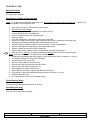
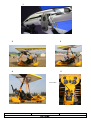
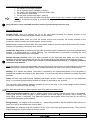
1
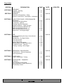
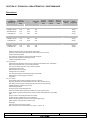
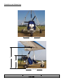
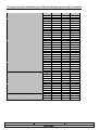
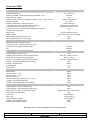
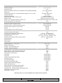
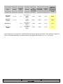
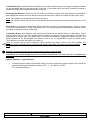
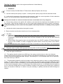
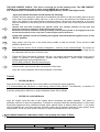
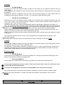
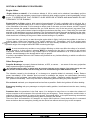
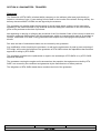
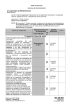
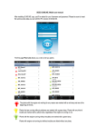
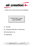
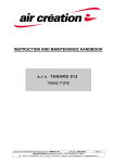
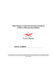
INSTRUCTION MANUAL
Dynamic
VOYAGEUR II
AIRFRAME
Trike n° : ........................................
Model: ............................................
Year:
MAUT – EN VOYAGEUR II
Edition : June 2005
..............................................
Copyright DTA – DTA ULM AU
SECTION 0 / PREAMBLE
Symbols
DANGER
Identifies an instruction which, if not observed, can cause damage
having fatal consequences.
ATTENTION
Identifies a significant instruction which, if not followed, can cause very
serious damage.
Reminder, Note :
Underlines a useful instruction which must be observed for the proper
use and operation of this COMBO airframe.
GMP
CF
Group – Motor/Propeller
See
Warning
The information and the descriptions contained in this Handbook correspond to the current design. That is,
the airframe as specified at the time of this publication. It is in no case exhaustive.
DTA improves its production constantly, and reserves the right to modify the specification, the drawing, the
characteristics, the model and/or the equipment, in the interests of Quality Assurance, without incurring
obligation.
The specifications are given in the metric system.
Note:
DTA SARL, a limited liability company, will not be held responsible for errors in translation. The original and
reference version of this document is in the French language, and held by DTA SARL
Copyright Details:
French Version DTA SARL – France 2005
English Version DTA ULM Australia – Australia 2005
No unauthorized copying of this document can be done with out consent, written or verbal, of DTA SARL
France.
MAUT-EN VOYAGEUR II
Edition : June 2005
Section : 0 - 02
Page Index
SECTION
DESIGNATION
PREAMBLE
Symbols – Warning
PAGE INDEX
SECTION 1 GENERAL
Reminder of Regulations - Safety
Amateur Construction - Description – Addresses
PAGE
SECTION 3
SECTION 4
SECTION 5
SECTION 6
0 – 02
0 – 03
JUNE 05
1 – 01
1 – 02
CARACTERISTIQUES - PERFORMANCES
Dimensions
Illustrations with dimensions
Accessories - Options
Carrying Capacity Calculation
Weight Limitations – Flight envelope
GMP 2 stroke Rotax 582 DCDI 2V
GMP 4 stroke Rotax 912 UL
GMP 4 stroke Rotax 912 ULSFR
Noise Level – Over flight Height
2 – 01
2 – 02
2 – 03
2 – 04
2 – 05
2 – 06
2 – 07
2 – 08
2 – 09
USE
Attaching/detaching the wing on the airframe
Illustrations
Adjustments – Pre-flight Checks
Use of the aircraft
Use of the tricycle
Starting Rotax 582 motors
Starting Rotax 912 and 912S motors
Pre-take off check – Take off
Cruising - Landing - End of flight
3 – 01
3 – 02
3 – 03
3 – 04
3 – 05
3 – 06
3 – 07
3 – 08
3 – 09
EMERGENCY PROCEDURES
Engine failure – Other emergencies
Use of a parachute
4 – 01
4 – 02
OTHER USES
Loads - Parachutist - Towing
5 – 01
GUARANTEES - TRANSFER
Guarantee
Card Transfer of Ownership
Card ULM delivery report (specimen)
Card Quality Control
6 – 01
6 – 02
6 – 03
6 – 04
MAUT – EN VOYAGEUR II
Edition : June 2005
UPDATED
JUNE 05
SECTION 0
SECTION 2
DATE
JUNE 05
JUNE 05
JUNE 05
JUNE 05
JUNE 05
Section : 0 - 03
SECTION 1 / GENERAL
This user's manual is supplemented by a Maintenance Handbook and the maintenance handbooks specific
to the wing, the engine and the parachute if necessary.
These handbooks define the conditions of use, as well as the requirements to maintain the airworthiness of
this aircraft.
The Pilot-in-Command (PIC):
- will use this aircraft (ULM) for sport, leisure and air work only
- is responsible for the state of airworthiness of the aircraft (ULM) which he pilots
- is holder of a valid current certificate and/or license, necessary to the particular activity
- an endorsement for this type of aircraft
- will abide by the Regulations and Rules pertaining to Aviation in the country of use and/or
registration.
- will conform to the recommendations stated in the Maintenance and Instruction manuals relating
to this aircraft (ULM), relating to, amongst other things, the flight envelope, the flight and weight
limitations and maintenance requirements
- will make sure that the aircraft (ULM) is used in conformity with its identification card and that it
has not been modified (it is forbidden to modify a whole or a part of the elements composing the
aircraft or to add elements by modifying the estimate of weight)
- will check that the identification/registration card is valid and that the identification markings (a
minimal height of 50 cm for France), attached to the under-surface of the aerofoil, are easily
readable
- will observe the elementary rules of flight safety: a thorough PRE-FLIGHT, PRE-TAKEOFF, PRELANDING and PRE-MANOEVER procedures and fly always with reference to the ‘CONE OF
FLIGHT SAFETY’, etc….
This document was drawn up in accordance with the current French Regulations, relating to
ultra/microlight (ULM) aircraft.
Note: Be aware of the Regulations regarding the maintenance of Microlight (ULM) aircraft
and the responsibilities of the Pilot in Command and/or owner of a Microlight (ULM) in the
country of registration of the Aircraft. DTA SARL will NOT be held responsible.
Be aware that the ULM in France are not, subject to certification.
Safety
Our aircraft (ULM) are delivered as standard without flight instrumentation. We recommend the installation
of an altimeter (in feet), an Air Speed Indicator (in the unit of speed measurement of the country of
registration), and a compass.
Check with the National Regulatory bodies of the country of use to ascertain the minimum required
instrumentation.
The information given by the instrumentation can be erroneous. The engine can break down. The movement
of air by nature is unpredictable. It can be sudden and violent and thus compromise the safety of the aircraft.
To pilot an aircraft (ULM) is an activity which can involve dangers and which requires adequate training.
MAUT – EN VOYAGEUR II
Edition : June 2005
Section : 1 – 01
Case of Amateur Construction
The DTA Voyageur II airframe, with its various motor combinations can be equipped with other weight-shift
delta wings. When manufactured by other than DTA; provided the characteristics of the wing, weight
limitations, hang bracket characteristics, control bar clearance, keel length, motor combination, etc, are
compatible with the DTA airframe under consideration. The position of the propeller axis requires wings with
"short keels". It is necessary to maintain a minimum distance of 10 cm between the wing (structure/wing)
and the propeller blade tip, this clearance MUST be in the full range if motion of the Control Bar.
The characteristics of the Voyageur II airframe, with its various motor combinations, accessories and
options, must also be compatible with limitations imposed by the manufacturer of the wing.
France: in accordance with the Law of 23 September 98 amended by the decree of May 15, 2001, the
assembler of a wing and a tricycle of different manufacturing origins is considered to be the manufacturer of
the aircraft (ULM), and consequently must ask for a "Carte d’identification provisoire d’ULM" in order to
carry out the flight tests, and to lodge with the Directeur de l’Aviation Civile a “Dossier Technique de
Construction Amateur".
Australia: This aircraft has been accepted as a complete aircraft. Alteration or modification is NOT allowed.
AU CAR 95.32
Worldwide: (please check with you Regulatory Authority)
The amateur builder will assume ALL responsibilities related to any modifications and the flight testing.
Caution: badly attached powerful motors, the presence of badly designed or poorly positioned fairing can
cause interactions between the wing and the airframe which can abruptly and negatively impact the behavior
of the aircraft and make it uncontrolable.
Description
Fuselage:
weight-shift (pendulum) two-seat tandem
Aerofoil:
flexible delta wing, models DYNAMIC 15/430, DYNAMIC 16/430, DYNAMIC 450
Motor:
2 stroke water cooled:
4 stroke water + oil cooled:
4 stroke water + oil cooled:
ROTAX 582 D.C.D.I. - 2V
ROTAX 912 UL
ROTAX 912 ULSFR
Manufacturers Address
Fuselage and Wing: D.T.A SARL
Aérodrome F-26200 MONTELIMAR
Tél. : 04 75 01 20 83 Fax 04 75 51 36 72 [email protected]
Motors:
ROTAX A- 4623 GUNSKIRCHEN – AUSTRIA, imported by
MAD 11 bd Albert 1° 98000 MONACO
Tél. : 00 377 93 30 17 40 Fax 00 377 93 30 17 60
MAUT – EN VOYAGEUR II
Edition : June 2005
Section : 1 - 02
SECTION 2 / TECHNICAL CARACTERISTICS - PERFORMANCE
Dimensions
Overall
lenght with
wing
Wingspan
Height with
wing
DYNAMIC 15/430
3,00
9,80
3,60
196 kg
DYNAMIC16/430
3,00
10,30
3,60
196 kg
DYNAMIC 450
3,00
10,20
3,60
201 kg
DYNAMIC 15/430
3,00
9,80
3,60
221 kg
DYNAMIC 450
3,00
10,20
3,60
226 kg
DYNAMIC 15/430
3,00
9,80
3,60
224 kg
DYNAMIC 450
3,00
10,20
3,60
229 kg
Model
VOYAGEUR II
DYNAMIC range
Lengt of
airframe
bare
Lenght of
airframe
faired
Width of
airframe
bare
2,58
3,02
1,95
Rotax 582C
Rotax 912UL
2,65
Rotax 912ULSFR
2,65
2,95
2,95
1,95
1,95
Width with
Empty
fairing
weight (std)
2,00
2,00
2,00
Airframe with aerodynamic profiles (powder coated white)
Cantileve vertical mast (with wing incidence angle limiter) and no front strut
Large all-moving foot pedals
Front wheel with suspension, brake and polyester mudguard
Aerodynamically profiled rear landing gear struts
2 positions adjustable front fork
For your security
Airframeand rigid passenger support frame constructed with stainless steel - TIG welded
Engine mount and rear axles - 4130 aircraft grade steel
Front and rear bucket ergonomic seats, carbon composite
6 plys 600x6'' aviation tyres
Powerful brakes on all 3 wheels
Parking brake on all 3 wheels
Foot and hand throttles (hand throttle protected by pilot seat)
Oleopneumatic rear landing gear suspension
Key ignition
For your comfort
Forward-tilting seats for better passenger access and refueling
Ergonomic seats with removable padded seat covers, blue (or black colours)
Easy raising of the wing due to specially placed pivot point and mast geometry
Padded passenger headrest blue (or black)
Rear passenger footrest
Documen,t pouch in rear passenger seat
Delivery with Rotax toolkit, spare fuses, butterfly nuts, hyper syphon fueling
Large capacity Voyageur side bags bue (or black), 20 litres, detachable with carry handles
GMP
Enngine mount 4130 aircrtaft grade steel TIG welved
75 litres injection moulded fuel tank with fuel gauge
Rubber mounted polyester instrument console (for integrate radio)
Ignition swithes / engine kill-swith / starter by key
Fuel gauge
Instrument console cover blue (or black)
GMP, accessories and instrumentation: CF section 2 - 06 à 2 - 08
MAUT – EN VOYAGEUR II
Edition : June 2005
Section : 2 - 01
Illustrations and dimensions
1.79
2.5 0
1.40
1.72 / 1.82
MAUT-EN VOYAGEUR II
Edition : June 2005
Section : 2 - 02
Accessories
Definition
Comments
Spats for rear wheels 6' '
Front fairing
Requires wheel spats
Skirt with integrated satchels
requires front fairing
Front bag
requires front fairing
Simple skirt
requires front fairing
Parachute GRS 3/450 out of container with attachments for 582
Parachute GRS 3/450 out of container with attachments for 912/912S
Dual nose-wheel steering controls
Dual foot throttle controls
Rear Seat Dual ignition controls
Towing Kit – Hang glider or Banner
specify 582 or 912/912S
Altimeter – 3 hand, barometric subscale Ø80mm
Analogue Air Speed indicator Ø 57mm or Ø 80mm
Variometer – analogue Ø 57mm
Pedestal Compass with mount on front bar
Compass – panel mount Ø 80mm
Radio VHF Icom ICA3
Case for radio VHF ICOM ICA3
Antenna whip granted
Intercom- Lynx external power or Alphatec
radio Filter type Lynx with 2 outlets (type RCA)
requires an auxiliary battery
requires an auxiliary battery
Battery 12V 7A for radio or strobe
Becker Radio
require a battery bracket
Becker Transponder – ‘Mode C’ type
Becker radio + Becker transponder
Strobe (flash-light)
Oil injection
requires console XXL Voyageur
requires an auxiliary battery
Rotax 582
Cylinder Head Temperature (CHT) in degrees Celsius
Exhaust Gas Temperature (EGT) in degrees Celsius
Rotax 582
Rotax 582
Intake Temperature
Carburettor heat – intake pre-heat by exhaust
Rotax 912/912S
Rotax 912 and 912S
Carburettor heat - intake pre-heat by liquid cooling circuit
Rotax 912 and 912S
Thermostat on the liquid coolant circuit
Rotax 912 and 912S
Torque limiter
Landing lights - Hella Xenon
Parking Cover
Control bar sleeves
Fuselage - Yellow - Colour RAL 1028
Rotax 912
according to motor and fairing
Options
Definition
Comment
Electric fuel priming pump (replaces the manual pump)
Electric starter (E type gearbox, replaces C type)
Rotax 582 with starter
Rotax 582
Propeller – Arplast three blade (replaces DUC F300 – three blade)
Rotax 582, 912, 912S
Propeller - Arplast four blade (replaces DUC F300 - three blade)
Rotax Flydat (replaces the standard analog instrumentation)
Rotax 582 - reduction i=3,47 becomes i=4
Rotax 912 et 912S
Console XXL (replaces STD console)
Inertia reel three-point seatbelt (mount plate replaces)
X-Large Satchels ‘Cape to Cape III’ (replaces Voyageur STD satchels)
MAUT – EN VOYAGEUR II
Edition : June 2005
passenger and/or pilot
Section : 2 - 03
Carrying Capacity Calculation guide with the following options and accessories
Motor / gearbox:
Empty weight – Voyageur II:
Wing:
DYNAMIC 15/430
DYNAMIC 16/430
DYNAMIC 450 (472,5)
Options:
Carb Heat – exhaust type (912/S)
Coolant circuit thermostat (912/S)
Oil circuit thermostat (912/S)
Torque limiter 912
Intake temperature
EGT or CHT (2 Stroke)
Starter 2-stroke + battery 16A
Oil injection
Option Arplast – three blade propeller
Option Arplast – four blade propeller
Option front strut (for cantilever mast)
Option 1 – inertial reel seatbelt
Side satchels XXL
Wheel Spats – type Feeling 6'' R + L
Front fairing including mounts
Simple skirt
Skirt with integrated satchels
Front bag
Altimeter 3 hand Ø 80mm
Airspeed indicator Ø 57mm ou Ø 80mm
Compass panel mount or pedestal
Vario or Altimeter Ø 57
Battery 12V8AH for radio or strobe
Intercom Lynx external mount
2 outlets RCA : Filter - Fusible
Antenna whip
Option Console XXL
Option Radio Becker
Dual Command nose gear wheel / gas foot / ignition
Training bars (for wing)
Parachute GRS 3 / 450 with bracket
Towing Kit Hang glider or Banner
Landing light – Hella Xenon
Wing Cover
Empty weight:
Maximum Takeoff Weight:
Carrying Capacity:
MAUT – EN VOYAGEUR II
Kg
582/C
142
912
167
912S
170
54,00
54,00
59,00
0,90
0,60
1,00
2,00
0,30
0,20
11,00
1,50
0,40
2,00
1,70
0.70
1,20
4,00
4,80
1,80
2,90
0,40
0,60
0,30
0,30
0,30
2,70
0,60
0,30
0,15
0,80
1,00
1,80
2,20
14.8
1,10
0,90
1,80
Edition : June 2005
Included
Section : 2 - 04
Empty weight
The empty weight indicated is that of a standard machine, complete, in flying condition, without options,
flight instrumentation, toolkit, documents or fuel.
Shown on the Weight Card given with the machine at the time of the delivery, the empty weight indicated is
that of the referred machine, with the accessories and options defined in the Delivery order and/or the final
Invoice, without toolkit, documents and fuel.
Weight Limits and COG
For your safety, in all the configurations, the maximum empty weight will be lower than:
DYNAMIC 450: 260 kg
DYNAMIC 16/430: 240 kg
DYNAMIC 15/430: 240 kg
CF: WING MANUEL
All loads should be carried as close to the COG of the aircraft as possible, i.e around the back seat, The
Maximum Take-Off Weight (MTOW) of each wing should ALWAYS be taken into account.
- The side satchels located on both sides of the back seat can carry 2 x 4 kg.
- The document pocket located at the rear the seat cover of the pilot seat can carry 2 kg.
- The front bag (front fairing configuration) can carry 3 kg.
To maintain the fuselage’s in-flight balance, the front seat, in all adjusted positions, should carry a
minimum of 50 kg and a maximum of 110 kg. The aircraft should NEVER be flown solo from the rear seat.
Load Limits
Operational Load Limits for the Voyageur fuselage:
• in flight:
+ 4 g 0 (- 2 g in gusts) at 472.5 kg
• on the ground:
+ 3g at 472.5 kg
Operational Load Limits of the Voyageur Aircraft (ULM): CF WING MANUEL (MAUT-DYN - EN)
Air Speed at MTOW
CF WING MANUEL
Flight Envelope Limitations
CF WING MANUEL
•
•
Maximum Angle of Bank
Maximum Pitch
60°
+/- 45°
The observance of this flight envelope is imperative. This Aircraft (ULM) is NOT designed for aerobatic flight.
Flight manoeuvres which result in negative load factors are completely prohibited.
Tow-release operations are authorized only by a progressive increase in pitch, idling engine, in straight and
level flight, nose down, at an minimum altitude of 500 meters.
Beyond the limits (bank 60°; pitch ± 45°), loss of stability or control, structural failure, or tumbling can occur.
MAUT – EN VOYAGEUR II
Edition : June 2005
Section : 2 - 05
Power Unit (GMP)
Brand - type - cycle
Rotax - 582 DCDI 2V - 2 stroke
A number of cylinders
2 cyl. - 580,7 cm3
Rotation of propeller (Aircraft (ULM) viewed from behind – PTO)
Double electronic ignition
Ignition check at 3500 rpm – max difference between circuit 1 and 2: 120 rpm
Integrated alternator
Number of carburettors or electronic injectors
Fuel (adapted according to climatic zone or conditions)
2-stroke oil (injected or mixed) and rotary valve
Proportion oil in mixture (advised semi-synthetic) 50:1 fuel/oil mix
Separate lubricating system
Gear box Oil
Radiator coolant
Manual priming pump for the fuel system
Electric priming pump for the fuel system
Maximum power output – maximum revolutions
Duration in minutes at maximum power
Continuous power – revolutions continuous power
Maximum governed speed not to be exceed
Idle
Fuel Consumption at 75% continuous power
Cooling fluid (radiator expansion-bottle recovery system)
Vanne thermostat on water circuit
Cylinder Head Temperature (CHT) in degree Celsius
Liquid Coolant Temperature in degree Celsius
Exhaust Gas Temperature (EGT) in degree Celsius
Exhaust – Steel (high temperature paint coating)
Exhaust – stainless Steel
Exhaust Silencer
Intake Silencer
Pull-start
Electric starter
Gear-box type B i = 2,58
Gear-box type C i = 3,47
Gear-box type C i = 4
Gear-box with electric starter type E i = 3,47 or 4
Propeller – Duc three-bladed F300
Propeller – Arplast three-bladed or four-bladed
Regulator – 3 phases with 2200 MF condenser
Ignition switches / engine kill-switch by key
Ignition switches / engine kill-switch / starter by key
Battery with power switch for the instrumentation
Fused electric circuit protection
Tachometer
Hour meter
Water Temperature Gauge
Cylinder Head Temperature (CHT)
Clockwise
STD
maximum drop 300 rpm
12V - 155W
2 Bing carburettors
min RON 90 or AVGAS 100LL
ASTM/CEC STD class API-TC
2,0%
O
API-GL5, SAE 85W-140 EP
Anti-freeze anti-corrosion for AL block
STD
Option
48 kW at 6500 rpm
6800 rpm
2000 rpm
20 L/h
STD
STD
Max 150° - optimal 110°/130°
Max 80° - min 65°
Max 650° - optimal 500°/620°
STD
Option
STD
STD
STD
Option
Option
STD
Option
Option
STD
Option
STD
STD
Option
Option (radio, strobe, electric starter)
STD
STD (analogue)
STD (analogue)
STD (analogue)
Option
Exhaust Gas Temperature (EGT)
Option
Manufacturer Data - also see the Rotax Maintenance & Users Handbooks
MAUT – EN VOYAGEUR II
Edition : June 2005
Section : 2 - 06
Make - type - cycle
Rotax - 912 UL - 4 stroke
Number of cylinders
4 cyl. - 1211 cm3
Compression ratio
Direction of propeller rotation from rear (rotation in reverse direction prohibited)
Dual ignition
Ignition check at 4000 rpm – maximum difference between 1 and 2: 120 rpm
Integrated alternator
Number of carburettors
Fuel (adapted according to climatic zone)
Radiator coolant
Engine oil (3L- adapted according to climatic zone)
Electric prime pump for the fuel system
Maximum power output – maximum revolutions
Duration in minutes at maximum power
Continuous power – revolutions continuous power
Maximum governed speed not to be exceed
Mini idle
Fuel consumption at 75% continuous power
Cooling fluid (radiator expansion-bottle recovery system)
Cooling oils (reservoir and radiator)
Cylinder Head Temperature in degree Celsius
Oil Temperature in degree Celsius
Oil Pressure in bar
Exhaust Gas Temperature (EGT) in degree Celsius
Stainless Exhaust
Exhaust Silencer
Intake Silencer
Electric starter
Integrated gearbox i = 2,27 or 2,43
Gearbox Torque limiter
Propeller – Duc three-bladed F300
Propeller –Arplast Three-bladed
Voltage regulator with condenser 22000 MF
Ignition switches / engine kill-switch / starter by key
Battery with power switch for the instrumentation
Fused electric circuit protection
Tachometer
Hour meter
Cylinder Head Temperature Indicator
Oil Pressure Gauge
Oil Temperature Gauge
Exhaust Gas Temperature (EGT)
Charge and Oil Pressure warning lights
Intake temperature gauge
Digital replacement of Analogue instrumentation
Carburettor heat – intake pre-heat by exhaust
Carburettor heat - intake pre-heat by liquid cooling circuit
Thermostat on water coolant circuit
Thermostat on oil circuit
9,0:1
left, counter clockwise
STD
Maximum drop 300 rpm
12V - 240W
2 Bing carburettors
min RON 90 or AVGAS 100 LL
antigel anti-corrosion for Al block
oil motor bike 4 stroke semi synth. API SG or SG
STD
59,6 kW at 5800 rpm
5 min at 5800 rpm
58 kW at 5500 rpm
5800 rpm
1400 rpm
16,2 L/h
STD
STD
max 150° - optimal 80°/100°
min 50° - max 140° - optimal 90/110°
min 1,5 bar - max 7 bar - optimal 2 - 5 bar
Max 650° - optimal 500°/620°
STD
STD
STD i =2,27
Option
STD
Option
STD
STD
STD
STD
STD (analogue)
STD (analogue)
STD (analogue)
STD (analogue)
STD (analogue)
Option
STD
Option
Option
Option
Option
Option
Option
Manufacturer Data - also see the Rotax Maintenance Handbook & Users Handbook
MAUT – EN VOYAGEUR II
Edition : June 2005
Section : 2 - 07
Make - type - cycle
Rotax - 912 ULSFR - 4 stroke
Number of cylinders
4 cyl. – 1352 cm3
Compression ratio
Direction of propeller rotation from rear (rotation in reverse direction prohibited)
Twin ignition
Ignition check at 4000 rpm – maximum difference between 1 and 2: 120 rpm
Integrated alternator
Number of carburettors or electronic injectors
Fuel (adapted according to climatic zone)
Radiator coolant
Engine oil (3L- adapted according to climatic zone)
Electric prime pump for the fuel system
Maximum power output – maximum revolutions
Duration in minutes at maximum power
Continuous power – revolutions continuous power
Maximum governed speed not to be exceed
Mini idle
Fuel consumption at 75% continuous power
Cooling fluid (radiator expansion-bottle recovery system)
10.5:1
left, counter clockwise
STD
Maximum drop 300 rpm
12V - 240W
2 Bing carburettors
min RON 90 or AVGAS 100 LL
Anti-freeze anti-corrosion for Al block
oil motor bike 4 stroke semi synthetic.
API SG SG
STD
73,5 kW at 5800 rpm
5 min at 5800 rpm
59 kW at 5250 rpm
5800 rpm
1400 rpm
18,2 L/h
STD
Cooling oils (reservoir and radiator)
Cylinder Head Temperature in degree Celsius
Oil Temperature in degree Celsius
Oil Pressure in bar
Exhaust Gas Temperature (EGT) in degree Celsius
Stainless Exhaust
Exhaust Silencer
Intake Silencer
Electric starter
Integrated gearbox i = 2,27 or 2,43
Gearbox Torque limiter
Propeller – Duc three-bladed F300
Propeller –Arplast Three-bladed
Voltage regulator with condenser 22000 MF
Ignition switches / engine kill-switch / starter by key
Battery with power switch for the instrumentation
Fused electric circuit protection
Tachometer
Hour meter
Cylinder Head Temperature Indicator
Oil Pressure Gauge
Oil Temperature Gauge
Exhaust Gas Temperature (EGT)
Charge and Oil Pressure warning lights
Intake temperature gauge
Digital replacement of Analogue instrumentation
Carburettor heat – intake pre-heat by exhaust
Carburettor heat - intake pre-heat by liquid cooling circuit
STD
max 150° - optimal 80°/100°
min 50° - max 140° - optimal 90/110°
min 1,5 bar - max 7 bar - optimal 2 - 5 bar
Max 650° - optimal 500°/620°
STD
STD
STD i =2,43
Option
STD
Option
STD
STD
STD
STD
STD (analogue)
STD (analogue)
STD (analogue)
STD (analogue)
STD (analogue)
Option
STD
Option
Option
Option
Option
Thermostat on water coolant circuit
Thermostat on oil circuit
Engine Cap
Option
Option
STD
Manufacturer Data - also see the Rotax Maintenance & Users Handbook
MAUT – EN VOYAGEUR II
Edition : June 2005
Section : 2 - 08
Height of
pass
Minimum
Height of pass
for a noise on
the ground of
65 dB
70 dB
150 m
253 m
69 dB
69 dB
150 m
228 m
DUC F300 ou
Arplast 3
Blade
71 dB
71 dB
150 m
280 m
DUC F300 ou
Arplast 3
Blade
70 dB
70 dB
150 m
253 m
Noise Level
noise level
Lm
Max weight Lr corrected
max power
Motor
Gearbox
Reduction
ratio
Propeller
Rotax 582
DCDI 2V
C (or E)
3,47
DUC F300 ou
Arplast
3Blade
70 dB
Rotax 582
DCDI 2V
C (or E)
4
Arplast
4 Blade
Rotax 912 UL
-
2,27
Rotax 912
ULSFR
-
2,43
Noise perceived on the ground Lh emitted when the aircraft flies at the height h, with maximum weight and
power, calculated according to the figures above, by applying the formula: Lh = Lr – 22 Log h/H.
MAUT – EN VOYAGEUR II
Edition : June 2005
Section : 2 - 09
SECTION 3 / USE
Wing Assembly
CF Wing Users Manuel
Attachment of wing on the fuselage
Note: for all the bolts assembled with wing nuts, the washer is placed under the wing nut. A safety pin
makes it possible to secure these nuts.
• Wing facing into wind, nose placed on the ground
• Rock the rear seat forward
• front fairing => remove the windshield (6 screws ¼ turn)
• remove the Ø 25 front strut (M6 bolt)
• remove the M10 locking bolt from the mast
• lower the mast
• bring the trike base’s, nose wheel to the wing control bar
• place the two parts of the wing’s hang cube around the keel, between the centring rings
• engage the trike base’s parking brake (the toothed brake lever)
• raise the wing by making it swivel on the control bar, centre and stabilize it
• slip the metal plates on both sides of the wing’s hang cube
• position, tighten and secure the M10 hang bolt
• position the security cable=> make a complete turn around the keel tube
• pass the cable under the tensioning cables and through the loop of the transverse bars
Note: the safety cable does not make a turn of the kingpost (1)
• screw without tightening the M10 wing nut of the wing safety cable (no washer) – secure
• Pre-Flight the Wing (CF Wing User’s Manual)
• grip the wing by the control bar
• raise the wing; holding it horizontal (2)
• slip the mast into its housing on the trike frame
• replace the mast’s M10 locking bolt (3)
• firmly tighten the wing nut and secure
• place the Ø 25 front strut, tighten the M6 bolt and secure
• front fairing => place the windscreen and screw the 6 screws ¼ turn (4)
• fold back the back seat
• Pre-Flight the trike frame (CF following pages)
Detaching the Wing
Follow the wing attachment procedure in reverse.
Refolding the wing
See the User's manual for the wing
MAUT – EN VOYAGEUR II
Edition : June 2005
Section : 3 - 01
1
2
3
4
5
Power switch
MAUT – EN VOYAGEUR II
Edition : June 2005
Section : 3 - 02
Adjustments
Trike Base:
• 2 positions of the front forks are possible. This modification requires the removal of the instrument
console.
• The front seat can be rolled slightly forward by unscrewing the support plugs, 10 mm at the
maximum. It is then necessary that a counter-nut be installed.
Wing:
• CF Wing Maintenance and Instruction Manual
Pre-Flight: a thorough and methodically pre-flight must be conducted before each flight.
Wing: CF Wing Maintenance and Instruction Manual
Trike Base:
Wing nuts tight and secured by the safety pin:
• M10 wing hang bolt
• M10 wing safety cable
• M6 front strut sleeve
• M10 Mast/frame locking bolt
Visually check the airworthiness and establish the serviceability of:
• the mast and the trike base
• the fairing of the trike base, the windscreen, the front removable bag, the side satchels
NOTE: ensure the side satchels and the front bag are closed
• the fork, the nose wheel and the front suspension
NOTE: move the machine several revolutions of the wheel in order to check for the absence of
suspicious noises
• the console and the electrical wire harness/loom to the engine
• sparkplugs, regulator, starter relay, battery
• front and rear seats
• seat belts, passed through the loops on the seat covers
Note : for solo flight => the rear seat belt must be locked and roller buckles it not used must be
secured by the safety pin connected to the body of the roller.
• Rear foot-rests
• fuel tank => fuel cap secured
• the fuel line to the engine, and that the fuel breather is functioning
• the fuel filter, the hand or electric priming pump, the fuel pump
• the carburettors, the air filter(s), the intake silencer (582)
• the throttles (hand, foot, double command) and the choke (cables and sheaths)
• the suspension tie rods and links, the ball joints, the axle assembly and the rear tyres
• the suspension arms with their oil and air shock absorbers (make – Fournalés)
• (the wheel spats)
• the motor cap (912/912S)
• the engine bracket, the mounts, the engine
• the radiator/s (security and free of blockage)
• radiator hoses for both the oil and water
• the exhaust system (springs, mounts, EGT probe security etc…)
• the propeller (damage, general airworthy state)
MAUT – EN VOYAGEUR II
Edition : June 2005
Section : 3 - 03
Check the security of the plugs and the levels in:
• the radiator of overflow container
• the oil injection tank (if installed) (2 temps)
• the rotary valve lubricating oil reservoir bottle (582)
• the oil reservoir (912/912S)
• the fuel tank (sufficient for flight + reserve)
Note : check that the fuel filter and the fuel tank is free of any trace of water or other impurities,
and also. A manual fuel pump is provided with each machine to make it possible to purge the
fuel tank.
Verify that there is FULL and FREE movement of the wing and nothing hinders the wing
Use of the tricycle
Throttle Pedal: when you depress the top of the right pedal forwards, the tension exerted on the
accelerator cable increases the engine speed, and conversely.
Throttle Control lever: when you push the throttle control lever forwards, the tension exerted on the
accelerator cable increases the engine speed, and conversely.
Choke Lever: located on the left side of the base beam, between the front seat and the instrument console.
Chokes are opened by pushing the lever forward.
Carburettor Heat Lever: located on the right side of the base beam, between the front seat and instrument
console, it is differentiated by a yellow marking. The carburettor-heat is activated by pushing the lever
forward. If activated always open completely
Ground Direction Control: when you exert pressure on the right-hand side pedal, the front steering
assembly the wheel turns towards the left. So, the aircraft (ULM) moves towards the left and conversely.
Because of the low stability of this type of machine, Powered Ground movement, is completely prohibited
without the wing attached.
Note: the geometry of the rear wheel-axle unit is such that when the tricycle is moved backwards, the shock
absorbers can be compressed slightly. Some forward movement will return them to their initial position.
Braking: all 3 wheels are braked. The brake is actuated by the forward depression of the left pedal. A
toothed rack enables the setting of the ‘park brake’. It is set manually and is released by rocking the pedal
forwards.
Seats: the front seat rocks forward, facilitating passenger access. It rests on its frame on two adjustable
plugs. In its normal upright position forward movement is restricted by the seat belt.
The rear seat, rocks forwards making it possible to remove the wing. In its normal upright position forward
movement is restricted by the seat belt.
The front seat must carry a pilot of greater than 55 kg and lower than 110 kg.
Pilot and passenger apparel: sport or walking shoes ensure good purchase of the feet on the pedals.
Helmet with visor or safety goggles in good condition (clean and without scratches), warm clothing, not
loose fitting, gloves if necessary. Pay particular attention that scarves and/or long hair do not come in
contact with the engine or the propeller.
Being Seating - the engine must be turned off - : when being seated in the rear position, take care not to
catch your foot in the hand throttle control cable.
Seat Belts: the seatbelts must be positioned at the level of the hips and tightened firmly. They must be
slipped through the loops located on the seat covers.
MAUT – EN VOYAGEUR II
Edition : June 2005
Section : 3 - 04
3-Point Seat belts: the blade of the shoulder belt must be located exactly on the nipple receptacle located
on the adjustable plate on the lap section of the belt. If the inertia reel is not used, a safety pin makes it
possible to secure the seatbelt blade to the inertia reel.
Fastening the Satchels: There are four (4) straps with buckles connect each side satchel to the airframe;
after clipping the buckle, the loose length of strap must be securely fasten to a higher section of the strap.
Note: each satchel can be loaded to a maximum of 4 kg.
Note: the satchels disturb the air flow on the radiator and can increase the coolant temperature by a few
degrees.
Fuel tank: is an injection moulded tank holding 75 litres and has a fuel quantity gauge. There is no fuel
cock on the standard model. There is NO purge valve. The manual pump delivered with the machine makes
it possible to purge the bottom of the tank.
Instrument Power: this relates to only those aircraft fitted with an electric starter or 7Ah battery. Check
that the ignition key is in the OFF position before actuating the electric circuit power switch. This switch is
protected by a ‘missile type’ red switch cover. The circuit is enabled by toggling the switch forward. The
electric starter can not be engaged if the Power Circuit is live. It is preferable to leave the switch in the
“ON" position as long as the engine is running (5).
Note: the electric circuit has a condenser. After switching the power circuit to the OFF position, the
discharge of this condenser takes a few seconds, during which time, the starter can still be engaged.
Note: the ignition switch and the light switches are independent of the instrument power switch.
After use, remove the ignition key to avoid accidental starting of the aircraft.
AUSTRALIA: It is a Federal Regulation that all Aircraft be disabled when not in use. The use of a propeller lock
is advised.
Ignition Switches – Light Switches:
•
The keyed ignition switch controls both ignition circuits as well as the electric starter, this carried out
using a keyed ignition switch by selecting OFF – L – R – BOTH - START
CF « Instrument Power».
MAUT – EN VOYAGEUR II
Edition : June 2005
Section : 3 - 05
Starting the engine: (refer to the engine manufacturer’s Users Manual)
•
582 Motors
1° - Fill the fuel tank (Fuel Mix Ratio: CF Rotax Users Manuel) Replace the fuel cap.
2° - Use the manual prime pump (or option – auxiliary electric prime pump) to fill the carburettor bowls
3° - Verify the full movement of the hand and foot throttles; verify the correct operation of both carburettor
barrels. You should hear both carburettor barrels closing together
Start-up at full throttle can cause the aircraft to become uncontrollable and is very dangerous.
4° - Ensure easy access to the ignition ‘kill’ switches, verify that both the hand and foot throttles are in the
idle position, verify that the machine can not move (park brake engaged and hold the aircraft if necessary).
Verify that nothing can be sucked into the propeller and finally that there is nobody in the propeller
arc.
5° - Actuate the choke (except when the engine is warm),
6°- Ensure that the hand throttle control lever is in the closed position.
7° - The Start:
• Hand start. Stand in front of the wing control bar which will be resting against the pilot seat. Turn the
ignition key to the "BOTH" position. Ensure that you are able to carry out an emergency engine stop
if necessary. Gentle draw the starter cord until some resistance is felt, then pull the start cord very
vigorously.
• Electric starter. Sit in the front seat, turn the ignition key to the “BOTH” position (CF above) then turn
the key to the "START" in order to engage the electric starter. Let the key return to the “BOTH”
position.
Note: the starter should not be engaged for more than 10 seconds at a time, after which, an uninterrupted
cooling period of two minutes should be observed.
8° - Bring the engine to about 2500 rpm and close the choke as soon as possible. Make sure that the hand
start cord is fully rewound, and that the hand start handle is secure against the pulley.
9° - Keep the engine at 2500 rpm.
10° - The ignition check is carried out at 3500 rpm: the engine revolution drop on only one of the two
ignition circuits should not drop by more than 300 rpm; the difference between the rev drop of both circuits
(L and R) should not exceed more than 120 rpm: Turn the key to "L" for 5 seconds, then "R" for 5 seconds,
then return the key to "BOTH"
11° - The thermostat installed in the liquid coolant circuit allows the engine to come to running temperature
quickly. The water radiator is situated at the back, under the airframe; avoid prolonged stationary engine
operation so as not to cause overheating. It is recommended that the coolant temperature not exceed 80°C
on the coolant temperature gauge. If conducting a fully loaded ground run, it is advisable that the engine be
run for 2 minutes at 3000 rpm to avoid the formation of vapour in the cylinder head, follow-up by a period of
about 10 seconds at 2000 rpm. In winter it may be necessary to partially occlude the airflow through the
radiator.
MAUT – EN VOYAGEUR II
Edition : June 2005
Section : 3 - 06
•
912 and 912S Motors
1° - Fill the fuel tank (Fuel : CF Rotax Users Manuel) Replace the fuel cap
2° - Turn the key on (CF above) : the discharge and oil pressure indicator lamps will come on. For the
Flydat : the discharge indicator lamp will come on and Flydat activates. Then to activate the auxiliary
electric fuel pump for at least 30 seconds to fill the carburettors bowls.
3° - Visually verify that both the carburettor butterfly valves are closed. This can be accomplished by,
several movements of the hand throttle lever then foot throttle pedal; this will let you verify the correct
operation of carburettor butterfly valves. A start-up with the butterflies wedged in the full throttle position can
cause the aircraft to become uncontrollable and is very dangerous.
4° - Ensure easy access to the ignition ‘kill’ switches, verify that both the hand and foot throttles are in the
idle position, verify that the machine can not move (park brake engaged and hold the aircraft if necessary).
Verify that nothing can be sucked into the propeller and finally that there is nobody in the propeller
arc.
5° - Actuate the choke (except when the engine is warm),
6°- Position the hand throttle lever a nearly closed position (no more than 10% open).
7° - Sit in the front seat, turn the ignition key to the "START" position in order to engage the starter.
Note: the electric starter should not be engaged for more than 10 seconds after which a cooling period of
two minutes should be observed.
8° - Set the engine revolutions to 2000 rpm. The electrical discharge indicator lamp as well as the oil
pressure indicator lamp must go out. For the Flydat refer to the Flydat Instruction Manual.
9° - The oil pressure must become stable within 2 to 4 second. (between 1,5 – 6 bars).
10° - Close the choke gradually, then visually check that the choke butterflies have returned to the off
position. Let the engine idle at up to 2500 rpm until oil temperature gauge indicates 60°C.
11° - The ignition check should be carried out at 3500 rpm. the engine revolution drop on only one of the
two ignition circuits should not drop by more than 300 rpm; the difference between the rev drop of both
circuits (L and R) should not exceed more than 120 rpm: Turn the key to "L" for 5 seconds, then "R" for 5
seconds, then return the key to "BOTH"
12° - The installation of the optional thermostats (three different options) on the coolant circuit, on the oil
circuit, or both; will allow a faster rise in engine temperature. As the water and oil radiators are placed at the
rear, avoid prolonged stationary operation of the engine as it may cause engine overheating.
Note: it is advised that a Cylinder Head Temperature of greater than 115° never be exceeded. If conducting
a fully loaded ground run, it is advisable that the engine be run for 30 seconds at 3000 rpm to avoid the
formation of vapour in the cylinder head, follow-up by a period of about 10 seconds at 2000 rpm. In winter it
may be necessary to partially occlude the airflow through the radiator(s).
Note: the oil pressure must stabilize in less than 10 seconds. An unstable oil pressure (oscillating between
1 and 3 bars, for example) is sign of air in the oil lubrication circuit => Turn off the engine immediately.
The propeller should not be hand turned in a direction opposite to its normal rotation direction.
MAUT – EN VOYAGEUR II
Edition : June 2005
Section : 3 - 07
THE PRE-TAKEOFF CHECK: This check is carried out at the holding point; The PRE-TAKEOFF
CHECK is an important procedure which should NEVER be overlooked.
It is a vital moment, concentrate on the ensuing flight and carry out the final flight checks.
A good pre-takeoff checklist should include the following
Visually check the hang bolt, particular the installation and security of the three safety pins at the top
of the mast (hang bracket, safety cable etc.), and on the wing, the tensions of the battens and dive
sticks, the closing of the under-surface inspection hatches, the security and presence of the nose
cap, the installation of the safety pins for the tensioning levers at the nose of the wing and the back of
the keel.
-
-
Helmets and seat belts (including the optional inertia reel shoulder harness) for the pilot and
passenger and than all luggage is firmly fastened and secured.
Ensure full movement of the front steering assembly, that the parking brake is not engaged, and of the
full and free movement of the control bar in both the pitch and roll directions.
Check both ignition circuits (CF Starting the engine) and check that the ignition key is in the
“BOTH” position.
-
Apply power until just prior to the brake being unable to hold the aircraft. There should be NO
propeller vibration at all.
-
Verify that the volume of fuel carried is adequate (+ reserve) for the intended flight. The volume of
unusable fuel is approximately one (1) litre. It is not recommended that even a very short flight should
be undertaken with less than 10 litres of fuel.
-
Check the Flight Instruments (Altimeter ASI etc.), the engine instruments (according to the type of
engine: oil pressure and temperature, cylinder head temperature / liquid coolant temperature,
electrical discharge light extinguished etc.).
NOTE: BRS parachute: Remove the safety pin
-
Check outside, other aircraft traffic, the direction of the wind…
-
Verify the correct operation and channel selection of the radio
Takeoff
•
ROTAX 582 Motor
Align the aircraft track with that of the runway before increasing the power gradually.
It is recommended that full-power is used during climb-out after takeoff. Co-incidentally, a reduction of
power causes the fuel/oil mixture to be reduced and must be avoided.
Avoid any quick power reduction or engine shutdown below 150 m altitude.
•
ROTAX 912 and 912S Motors
Align the aircraft track with that of the runway before increasing the power gradually. 75% power is
generally sufficient for pilot-only operations. Full power is necessary with pilot and passenger or in the case
single-seat operations when conditions dictate (short takeoff areas, at altitude heavy load…). Full power
can be sustained for only three minutes. Carefully watch the oil pressure and the oil and cylinder head
temperatures. Avoid any quick power reduction or engine shutdown below 150 m altitude.
NO takeoff should be undertaken with a fuel quantity less than 10 litres.
MAUT – EN VOYAGEUR II
Edition : June 2005
Section : 3 - 08
Cruising
• ROTAX 582 Motor
According to the load, and indicated speed, straight and level flight can be maintained between 50% and
100% power.
Avoid rapid and brutal changes in power which generate quick fluctuations in temperature and overly stress
the gearbox.
Although not common, carburettor icing can occur with two-stroke engines; at cruise speed when the
atmospheric temperature is between -10° and + 10° and that the relative humidity is high.
•
ROTAX 912 and 912S Motors
According to the load, and indicated speed, straight and level flight can be maintained between 40% and
75% of the power. Avoid rapid and brutal changes in power which generate quick fluctuations in
temperature and overly stress the gearbox.
Carburettor icing can occur, even at cruising speed, when the atmospheric temperature is between -10°
and + 10° and that the relative humidity is high. Symptoms include a gradual decrease in engine speed and
rough running. DO NOT decrease the throttle, but to increase to FULL POWER to allow the carburettors "to
swallow" the ice particles forming in the carburettors, then return the throttle to the desired position.
Option carburettor de-icing by exhaust preheat: push the ‘carb heat’ lever fully forward (remember: all or
nothing). The power loss, fully open, will be approximately 300 rpm.
Option carburettor de-icing by heat scavenge from the liquid coolant: with this option the ‘warmed’ air intake
is always on.
The translucent fuel tank carries 75 litres, and is equipped with an analogue fuel level gauge on the
instrument console.
A landing MUST take place before the remaining fuel volume decreases to less than 5 litres.
Landing
When flying in conditions conducive to icing, (see above), the throttle reduction should be gradually in order
to enable the detection of the start of carburettor icing.
The approach, in calm weather, should be carried out at 1.3 of Vso, that is, close to 80 km/h. Factors such
as altitude, the temperature, the load, the atmospheric instability, wind conditions are some of the many
factors which would suggest an increased approach speed.
End of the flight
• ROTAX 582 Motor
Let the engine run at 3000rpm for 2 minutes to facilitate even cooling, this should be followed by a short
period of 10 seconds at idle before shutting down.
• 912 and 912S Motors
Let the engine run at 3000 rpm for 30 seconds to facilitate even cooling before shutting down.
For any engine equipped with an electric starter: switch the Instrument Power switch to the OFF position and
to remove the key of the keyed ignition.
For any Aircraft equipped with a pyrotechnic parachute (BRS): secure the parachute safety pin.
Secure the park brake, secure the aircraft wing and, if possible, park the aircraft out of direct sunlight.
NOTE: after engine shutdown, the muffler can retain heat capable of causing burns for ten minutes.
MAUT VOYAGEUR II
Edition : June 2005
Section : 3 - 09
SECTION 4 / EMERGENCY PROCEDURES
Engine failure
Engine failure on takeoff : if an minimum altitude of 100 m could not be obtained, immediately pull the
control bar in; gain and maintain a speed close to 80 km/h while seeking a place to land immediately in front
to you. IT IS IMPERATIVE THAT CORRECT GLIDE SPEED BE ATTAINED AND MAINTAINED! DO NOT
TURN BACK TO THE RUNWAY!
Engine failure in flight: adopt a glide speed of approximately 70 km/h. preferably with a tail wind. As a
careful pilot, you should always fly in "a cone of flight of safety", at sufficient altitude, with an understanding
of the orientation of the wind. It is not enough to simply land on the area you have chosen, do NOT forget to
take into account the possible obstacles that you could discover only at the last minute (eg power lines,
ditches etc…) and ground related or/and mechanical turbulence that may occur. Check that your seat belt
and that of the passenger is securely fastened. The final approach should be made preferably into the wind.
With the onset of night the approach should be with the sun at the rear if possible. Your aircraft will be quiet,
check that there is nobody on the ground. Make a short landing run if possible.
If you have time, you can try to start the engine again whilst in flight. Verify that the problem is not from a
memory lapse: choke lever actuated, icing, ignition switches off... Remember, even if the engine starts
again remains in the cone of flight safety and land on the area initially considered, so as to determine the
possible origin of the engine failure BEFORE continuing the flight.
NOTE. In most countries any accident or any incident affecting or which can affect the safety of an aircraft,
on the ground or in that country’s airspace MUST be declared by the pilot in command to the relevant
Authorities. Within the accident or any incident report is a specific declaration as to if the accident or the
incident, caused damage to the aircraft and/or injury to people.
It is often a punishable offence to NOT declare any accident or any incident affecting or which can affect the
safety of an aircraft
Other Emergencies
Propeller Breakage: improperly fastened helmets, a GPS, a camera … are some of the many projectiles
likely to pass through the propeller arc.
All removable objects taken on board must be securely fastened to the airframe. The helmet clasp, the seat
belt (and the seat belt shoulder harness strap) are to be checked during the PRE TAKEOFF check.
The vibration caused by the breakage of, or damage to a propeller blade/s is extremely violent. Reduce
power immediately! (If the vibration does not seem to endanger the engine, the carburettors (becoming
detached) or the occupants, land safely before cutting the engine.) Otherwise switch the ignitions to the
OFF position immediately. Then verify the state of the sail/wing before making any other decision.
Fire on board: maintain your airspeed and land as fast as possible. Switch the ignitions off before landing.
Emergency landing: ask your passenger to adopt the safety position, head lowered onto the arms, leaning
forward.
Parachute Use: the parachute is the final resort; it is designed to save lives or to reduce the chance of
serious wounds to the occupants of the aircraft during an emergency. These emergencies could include: a
collision in flight, a total loss of control of the aircraft, a structural failure, or the pilot becoming unconscious
without the possibility of the passenger being able to control/fly the aircraft.
There are other circumstances, for example; an engine failure above a forest and the pilot in command
does not believe that an emergency landing can be carried out without serious injury to the occupants.
MAUT – EN VOYAGEUR II
Edition : June 2005
Section : 4 - 01
As far as possible, the engine should be stopped before releasing the parachute.
The parachute release handle is positioned between the front seat and the instrument console, on the base
beam, between the legs of the person in the front seat. Although difficult, the release handle can be
reached from the back seat. The release handle is pulled upward. (CF The parachute manufacturer’s
Handbook). This parachute release sequence should be explained by the pilot to the passenger, before
flight.
After a normal opening, the aircraft will have a strong nose-down attitude.
If the engine could not be stopped, it is possible that the wire rope connecting the parachute to the Airframe
could be entangled in the propeller. The nose-down attitude will be even more significant.
Before impact adopt the safety position.
Note: before starting a flight, remove the parachute release safety pin. The parachute release procedure
must be explained to the passenger.
The parachute release safety pin must be reinstalled after the landing and before leaving the aircraft.
Note: the installation of a parachute is an option.
Installation of a parachute: CF Voyageur II Maintenance Manuel (MANE – EN VOYAGEUR II) Section 3-06
« Appendices »
Safety pin
Parachute
MAUT – EN VOYAGEUR II
Edition : June 2005
Section : 4 - 02
SECTION 5 / OTHER USES
Load carriage, Reconnaissance Equipment, Surveillance, Line Inspection
The load must be situated close to the back seat, those places nearest to the centre of gravity of the
aircraft, accounting for the MTOW (maximum takeoff weight) indicated for the wing used. The freedom of
movement of the wing must be unhindered, in particular take care that no load, blocks or rubs on the back
longitudinal cables.
The attachment of a video or still camera on the wing tip is acceptable, with the proviso that a weight limit of
1,5 kg be observed and that a counter weight (of equal weight) is mounted in a similar position on the
opposite wing tip. The wing’s inertia will be greatly increased.
Dropping of parachutists
The parachutist must be seated in the back seat (in NO case in the front seat).
Jump Procedure: cut engine, best glide speed, make a gentle turn. The parachutist jumps to the outside of
the turn. It is imperative that this procedure be practiced on the ground.
Glider, hang glider or banner towing
It is essential the tow release mechanism is able to quickly release the glider or banner, even under
tension/load. A ‘weak link’ rated at 40daN MUST be installed between the ‘Tug aircraft’ and the glider or
banner.
NOTE :
BE AWARE THAT EACH COUNTRY HAS ITS OWN RULES AND REGULATIONS REGARDING
WHAT CONSITUTES RECREATIONAL AVIATION AND WHAT CONSTITUTES AIRWORK.
THERE ARE OFTEN LISCENCING REQUIRMENTS FOR THE TWO DIFFERENT ACTIVITIES. IT
IS IMPERATIVE THAT EACH OWNER/PILOT BE AWARE OF THE RULES AND REGULATIONS
PERTAINING TO THE OPERATIONS THEY INTEND TO CARRY OUT. DTA DOES NOT
CONDONE ANY UNLAWFUL AERIAL ACTIVITY.
MAUT VOYAGEUR II
Edition : June 2005
Section : 5 - 01
SECTION 6 / GUARANTEES - TRANSFER
Guarantee
The Guarantee of DTA SARL (a limited liability company) on the airframe (trike base) and the wing is
limited to a duration of one (1) year starting from the date on the invoice of the aircraft. During delivery, the
delivery document MUST be filled out and signed by the customer.
The guarantee only applies within the framework of aircraft usage which conforms to the instructions
appearing in the User's manuals or any technical document stating the conditions of use of the aircraft
given to the purchaser at the time of purchase.
Not respecting or obeying or infringing the provisions of the Civil Aviation Code (of the country in which the
aircraft is registered or being flown) and the related texts, which as a consequence result in an accident or
incident, exonerates DTA SARL of any guaranteed with respect to the infringing aircraft operator or the
aircraft.
Fair wear and tear of maintenance items are not covered by this guarantee.
Any modification of the aircraft by the purchaser, as well as the replacement of parts by parts not being of
DTA origin, will involve the forfeiture of the guarantee of DTA SARL unless the replacement has first been
approved in writing by DTA SARL.
The guarantee is limited to the replacement or repair in the workshops of DTA SARL or by a DTA SARL
approved workshop.
The guarantee covering the engine and its accessories, the propeller, that equipment not built by DTA
SARL, are covered by the conditions and guarantee by the manufacturers of those products.
The obligations of DTA SARL stated above constitute the limit of the guarantee.
MAUT – EN VOYAGEUR II
Edition : June 2005
Section : 6 - 01
Transfer of Ownership
We hope that you are fully satisfied with your DTA Microlight and that it enables you to enjoy many hours of
flying pleasure.
In the event of a transfer of ownership or of a second hand purchase and in order to carry out follow-up,
DTA SARL would be grateful to you if you agree to return the document below to the following address:
DTA SARL
Aérodrome de Montélimar Ancône
26200 MONTELIMAR
France
Tél : +33 (0)4 75 01 20 83
Fax : +33 (0)4 75 51 36 72
Former owner:
Name :
Address :
Post/Zip Code and City:
Country
DTA Microlight / trike base / wing *
Year of issue of 1st Identification Card ** :
Number of hours:
Base * Evolution / Voyageur / Feeling / Combo
Serial n° **
Wing * DYNAMIC 16-99
DYNAMIC16 / 430
DYNAMIC 15-99 DYNAMIC 15/430 DYNAMIC 450
Other :
Serial n° **
Make, type and serial n° **of motor :
* cross out incorrect choice
** See the Identification Card and/or cover of your
Handbooks
New owner:
Name:
Address:
Post/Zip Code and City:
Country:
Telephone :
E-mail :
MAUT – EN VOYAGEUR II
Edition : June 2005
Section : 6 - 02
ULM DELIVERY STATEMENT
Wing:
Serial N°:
DYNAMIC 15/430 - 16-430
………………………..
Trike Frame:
Serial N°:
COMBO
EVOLUTION
……………………….
Motor :
Serial N°:
503 - 582 Gearbox C - E
………………………..
-
450
FEELING
VOYAGEUR II
912 - 912 S
I the undersigned, ……………………………………………………………………………………..
Residing at
…………………………………………………………………………………………
Testify:
• that the aircraft (ULM) delivered by …………………………………………………….. the
Distributor is in conformity with the Purchase order
• that the commissioning tests of this aircraft (ULM) was carried out in my presence
• that indications relating to « Wing tests » and « Trike tests » are in conformity with what the
instruments indicate.
• that I have received the DTA SARL Users and Maintenance Handbooks specific to the trike
base, the engine, the wing and the parachute if necessary, have read the documentation, have
accepted and understood the instructions, the recommendations and the prohibitions stated in
these documents.
• taken note that the empty weight of the delivered Aircraft is …………………Kg, the MTOW
(Maximum Take Off Weight) is …………………. Kg, is able to carry ………………….. Kg.
Signature of Purchaser
…………………………………
Date
..............................................
Signature of Witness
..............................................
Print Witness Name
............................................
MAUT – EN VOYAGEUR II
Edition : June 2005
Section : 6 - 03
Quality Control Card
We are very attentive to the comments and remarks of our users and clients! We endeavour to constantly
improve our products. The maintenance of the quality of our manufacture is an abiding concern. Many
procedural checks have been installed at each stage of manufacture and assembly of your aircraft so that it
is in conformity with our stringent quality requirements.
Nevertheless if you encounter a problem while using your machine, no matter what, we would appreciate if
you would fill out this card and return it as soon as possible. We can try to remedy your problem as fast as
possible.
Name: ……………………………………………………………………………….
Address : ……………………………………………………………………………
Address : ……………………………………………………………………………
Post/Zip Code: …………………… City : …………………………………………
Country : …………………………………………………………………………….
Telephone N°: ………………………………………………………………………
E–Mail : ………………………………………………………………………………
Aircraft Type :………………………………………………………………………..
Frame N° : ……………………… Year : ………………………………………..
Wing N° : …………………………... Motor N° : ……………………………………
Distributor :………………………………………………………………………….
N° hours of flight : ……………………………………………………………………
Encountered problem (schema, photograph if possible) :
MAUT – EN VOYAGEUR II
Edition : June 2005
Section : 6 - 04