1
ABB Drives
User's Manual
FlashDrop
MFDT-01
บริษัท ที.จี. คอนโทรล จำกัด
1683 ทาวน์อินทาวน์ ซอย 9 แขวงพลับพลา เขตวังทองหลาง กรุงเทพฯ 10310
โทร. 02-530-9090 แฟกซ์. 02-530-9933 www.tgcontrol.com, www.facebook.com/tgcontrol
FlashDrop
MFDT-01
User's Manual
3AFE68591074 Rev B
EN
EFFECTIVE: 5.3.2007
2007 ABB Oy. All R ghts Reserved.
บริษัท ที.จี. คอนโทรล จำกัด
1683 ทาวน์อินทาวน์ ซอย 9 แขวงพลับพลา เขตวังทองหลาง กรุงเทพฯ 10310
โทร. 02-530-9090 แฟกซ์. 02-530-9933 www.tgcontrol.com, www.facebook.com/tgcontrol
บริษัท ที.จี. คอนโทรล จำกัด
1683 ทาวน์อินทาวน์ ซอย 9 แขวงพลับพลา เขตวังทองหลาง กรุงเทพฯ 10310
โทร. 02-530-9090 แฟกซ์. 02-530-9933 www.tgcontrol.com, www.facebook.com/tgcontrol
5
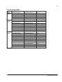
Table of contents
About the manual . . . . . . . . . . . . . . . . . . . . . . . . . . . . . . . . . . . . . . . . . . . . . . . . . . . . . . . . . . . . . . 9
What th s chapter conta ns . . . . . . . . . . . . . . . . . . . . . . . . . . . . . . . . . . . . . . . . . . . . . . . . . . . . . . . . 9
Intended aud ence . . . . . . . . . . . . . . . . . . . . . . . . . . . . . . . . . . . . . . . . . . . . . . . . . . . . . . . . . . . . . . . 9
Add t onal nformat on for users . . . . . . . . . . . . . . . . . . . . . . . . . . . . . . . . . . . . . . . . . . . . . . . . . . . . . 9
Product tra n ng . . . . . . . . . . . . . . . . . . . . . . . . . . . . . . . . . . . . . . . . . . . . . . . . . . . . . . . . . . . . . . . . . 9
Product and serv ce nqu r es . . . . . . . . . . . . . . . . . . . . . . . . . . . . . . . . . . . . . . . . . . . . . . . . . . . . . . 9
Prov d ng feedback on ABB Dr ves manuals . . . . . . . . . . . . . . . . . . . . . . . . . . . . . . . . . . . . . . . . . . . 9
Getting started . . . . . . . . . . . . . . . . . . . . . . . . . . . . . . . . . . . . . . . . . . . . . . . . . . . . . . . . . . . . . . . . 11
What th s chapter conta ns . . . . . . . . . . . . . . . . . . . . . . . . . . . . . . . . . . . . . . . . . . . . . . . . . . . . . . . 11
Overv ew . . . . . . . . . . . . . . . . . . . . . . . . . . . . . . . . . . . . . . . . . . . . . . . . . . . . . . . . . . . . . . . . . . . . . 11
Unpack ng . . . . . . . . . . . . . . . . . . . . . . . . . . . . . . . . . . . . . . . . . . . . . . . . . . . . . . . . . . . . . . . . . . . . 12
Type des gnat on label . . . . . . . . . . . . . . . . . . . . . . . . . . . . . . . . . . . . . . . . . . . . . . . . . . . . . . . . . . 12
Compat b l ty . . . . . . . . . . . . . . . . . . . . . . . . . . . . . . . . . . . . . . . . . . . . . . . . . . . . . . . . . . . . . . . . . . 13
Safety nstruct ons . . . . . . . . . . . . . . . . . . . . . . . . . . . . . . . . . . . . . . . . . . . . . . . . . . . . . . . . . . . . . . 13
Installat on and comm ss on ng flowchart . . . . . . . . . . . . . . . . . . . . . . . . . . . . . . . . . . . . . . . . . . . . 14
Prov d ng the programm ng t p w th a safety l ne . . . . . . . . . . . . . . . . . . . . . . . . . . . . . . . . . . . . . . . 15
Charg ng . . . . . . . . . . . . . . . . . . . . . . . . . . . . . . . . . . . . . . . . . . . . . . . . . . . . . . . . . . . . . . . . . . . . . 15
Connect ng . . . . . . . . . . . . . . . . . . . . . . . . . . . . . . . . . . . . . . . . . . . . . . . . . . . . . . . . . . . . . . . . . . . 15
Ma ns electr c ty supply (AC power source) - charger - base un t . . . . . . . . . . . . . . . . . . . . . . . 15
FlashDrop Control Panel - base un t . . . . . . . . . . . . . . . . . . . . . . . . . . . . . . . . . . . . . . . . . . . . . 15
PC - base un t . . . . . . . . . . . . . . . . . . . . . . . . . . . . . . . . . . . . . . . . . . . . . . . . . . . . . . . . . . . . . . 15
FlashDrop - dr ve . . . . . . . . . . . . . . . . . . . . . . . . . . . . . . . . . . . . . . . . . . . . . . . . . . . . . . . . . . . . 16
How to nstall Dr vePM tool, vers on 1.1 or later . . . . . . . . . . . . . . . . . . . . . . . . . . . . . . . . . . . . . . . 16
How to download parameter templates to the FlashDrop . . . . . . . . . . . . . . . . . . . . . . . . . . . . . . . . 17
Stor ng . . . . . . . . . . . . . . . . . . . . . . . . . . . . . . . . . . . . . . . . . . . . . . . . . . . . . . . . . . . . . . . . . . . . . . . 17
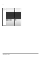
Operation . . . . . . . . . . . . . . . . . . . . . . . . . . . . . . . . . . . . . . . . . . . . . . . . . . . . . . . . . . . . . . . . . . . . 19
What th s chapter conta ns . . . . . . . . . . . . . . . . . . . . . . . . . . . . . . . . . . . . . . . . . . . . . . . . . . . . . . . 19
Us ng the FlashDrop for parametr zat on of dr ves . . . . . . . . . . . . . . . . . . . . . . . . . . . . . . . . . . . . . 19
FlashDrop parametr zat on flowchart . . . . . . . . . . . . . . . . . . . . . . . . . . . . . . . . . . . . . . . . . . . . . 21
FlashDrop Control Panel and ts operat on . . . . . . . . . . . . . . . . . . . . . . . . . . . . . . . . . . . . . . . . . . . 22
Control panel overv ew . . . . . . . . . . . . . . . . . . . . . . . . . . . . . . . . . . . . . . . . . . . . . . . . . . . . . . . . 22
Status l ne . . . . . . . . . . . . . . . . . . . . . . . . . . . . . . . . . . . . . . . . . . . . . . . . . . . . . . . . . . . . . . . 23
Operat on pr nc ples . . . . . . . . . . . . . . . . . . . . . . . . . . . . . . . . . . . . . . . . . . . . . . . . . . . . . . . . . . 23
How to do common tasks . . . . . . . . . . . . . . . . . . . . . . . . . . . . . . . . . . . . . . . . . . . . . . . . . . . . 24
Check ng the propert es and compat b l ty . . . . . . . . . . . . . . . . . . . . . . . . . . . . . . . . . . . . . . . . . 24
T me & Date mode . . . . . . . . . . . . . . . . . . . . . . . . . . . . . . . . . . . . . . . . . . . . . . . . . . . . . . . . . . . 25
How to set the date and t me . . . . . . . . . . . . . . . . . . . . . . . . . . . . . . . . . . . . . . . . . . . . . . . . . 25
How to adjust the d splay contrast . . . . . . . . . . . . . . . . . . . . . . . . . . . . . . . . . . . . . . . . . . . . . 26
How to v ew nformat on about the dr ve connected to the FlashDrop . . . . . . . . . . . . . . . . . . 27
บริษัท ที.จี. คอนโทรล จำกัด
1683 ทาวน์อินทาวน์ ซอย 9 แขวงพลับพลา เขตวังทองหลาง กรุงเทพฯ 10310
โทร. 02-530-9090 แฟกซ์. 02-530-9933 www.tgcontrol.com, www.facebook.com/tgcontrol
6
How to download templates from the Internet . . . . . . . . . . . . . . . . . . . . . . . . . . . . . . . . . . . .
Parameters mode . . . . . . . . . . . . . . . . . . . . . . . . . . . . . . . . . . . . . . . . . . . . . . . . . . . . . . . . . . .
How to n t al ze (create) a parameter set . . . . . . . . . . . . . . . . . . . . . . . . . . . . . . . . . . . . . . .
How to upload a parameter set from the dr ve . . . . . . . . . . . . . . . . . . . . . . . . . . . . . . . . . . .
How to v ew the parameter set nformat on . . . . . . . . . . . . . . . . . . . . . . . . . . . . . . . . . . . . . .
How to ed t a parameter set . . . . . . . . . . . . . . . . . . . . . . . . . . . . . . . . . . . . . . . . . . . . . . . . .
How to ed t the value of a parameter n a set . . . . . . . . . . . . . . . . . . . . . . . . . . . . . . . . . . . .
How to v ew and ed t the values of changed parameters n a set . . . . . . . . . . . . . . . . . . . . .
How to ed t the v s b l ty of a parameter n a set . . . . . . . . . . . . . . . . . . . . . . . . . . . . . . . . . .
How to ed t the v s b l ty of a parameter group n a set . . . . . . . . . . . . . . . . . . . . . . . . . . . . .
How to delete a parameter set . . . . . . . . . . . . . . . . . . . . . . . . . . . . . . . . . . . . . . . . . . . . . . .
How to download a parameter set to a dr ve . . . . . . . . . . . . . . . . . . . . . . . . . . . . . . . . . . . . .
How to v ew nformat on about the FlashDrop . . . . . . . . . . . . . . . . . . . . . . . . . . . . . . . . . . .
How to f nd out the control panel vers on . . . . . . . . . . . . . . . . . . . . . . . . . . . . . . . . . . . . . . .
28
29
30
32
34
35
36
38
40
41
42
43
44
44
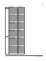
Fault tracing . . . . . . . . . . . . . . . . . . . . . . . . . . . . . . . . . . . . . . . . . . . . . . . . . . . . . . . . . . . . . . . . .
45
What th s chapter conta ns . . . . . . . . . . . . . . . . . . . . . . . . . . . . . . . . . . . . . . . . . . . . . . . . . . . . . . .
Error messages . . . . . . . . . . . . . . . . . . . . . . . . . . . . . . . . . . . . . . . . . . . . . . . . . . . . . . . . . . . . . . .
45
45
Maintenance and hardware diagnostics . . . . . . . . . . . . . . . . . . . . . . . . . . . . . . . . . . . . . . . . . .
47
What th s chapter conta ns . . . . . . . . . . . . . . . . . . . . . . . . . . . . . . . . . . . . . . . . . . . . . . . . . . . . . . .
Safety . . . . . . . . . . . . . . . . . . . . . . . . . . . . . . . . . . . . . . . . . . . . . . . . . . . . . . . . . . . . . . . . . . . . . . .
Ma ntenance ntervals . . . . . . . . . . . . . . . . . . . . . . . . . . . . . . . . . . . . . . . . . . . . . . . . . . . . . . . . . .
Software . . . . . . . . . . . . . . . . . . . . . . . . . . . . . . . . . . . . . . . . . . . . . . . . . . . . . . . . . . . . . . . . . . . . .
Base un t . . . . . . . . . . . . . . . . . . . . . . . . . . . . . . . . . . . . . . . . . . . . . . . . . . . . . . . . . . . . . . . . . . . .
Battery replacement . . . . . . . . . . . . . . . . . . . . . . . . . . . . . . . . . . . . . . . . . . . . . . . . . . . . . . . . . .
Control panel . . . . . . . . . . . . . . . . . . . . . . . . . . . . . . . . . . . . . . . . . . . . . . . . . . . . . . . . . . . . . . . . .
Clean ng . . . . . . . . . . . . . . . . . . . . . . . . . . . . . . . . . . . . . . . . . . . . . . . . . . . . . . . . . . . . . . . . . . .
Battery . . . . . . . . . . . . . . . . . . . . . . . . . . . . . . . . . . . . . . . . . . . . . . . . . . . . . . . . . . . . . . . . . . . .
LEDs . . . . . . . . . . . . . . . . . . . . . . . . . . . . . . . . . . . . . . . . . . . . . . . . . . . . . . . . . . . . . . . . . . . . . . . .
47
47
47
47
48
48
48
48
48
49
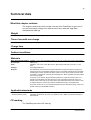
Technical data . . . . . . . . . . . . . . . . . . . . . . . . . . . . . . . . . . . . . . . . . . . . . . . . . . . . . . . . . . . . . . .
51
What th s chapter conta ns . . . . . . . . . . . . . . . . . . . . . . . . . . . . . . . . . . . . . . . . . . . . . . . . . . . . . . .
We ght . . . . . . . . . . . . . . . . . . . . . . . . . . . . . . . . . . . . . . . . . . . . . . . . . . . . . . . . . . . . . . . . . . . . . .
T me of use w th one charge . . . . . . . . . . . . . . . . . . . . . . . . . . . . . . . . . . . . . . . . . . . . . . . . . . . . .
Charge t me . . . . . . . . . . . . . . . . . . . . . . . . . . . . . . . . . . . . . . . . . . . . . . . . . . . . . . . . . . . . . . . . . .
Amb ent cond t ons . . . . . . . . . . . . . . . . . . . . . . . . . . . . . . . . . . . . . . . . . . . . . . . . . . . . . . . . . . . . .
Mater als . . . . . . . . . . . . . . . . . . . . . . . . . . . . . . . . . . . . . . . . . . . . . . . . . . . . . . . . . . . . . . . . . . . . .
Appl cable standards . . . . . . . . . . . . . . . . . . . . . . . . . . . . . . . . . . . . . . . . . . . . . . . . . . . . . . . . . . .
CE mark ng . . . . . . . . . . . . . . . . . . . . . . . . . . . . . . . . . . . . . . . . . . . . . . . . . . . . . . . . . . . . . . . . . . .
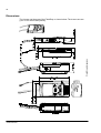
D mens ons . . . . . . . . . . . . . . . . . . . . . . . . . . . . . . . . . . . . . . . . . . . . . . . . . . . . . . . . . . . . . . . . . . .
51
51
51
51
51
51
51
51
52
บริษัท ที.จี. คอนโทรล จำกัด
1683 ทาวน์อินทาวน์ ซอย 9 แขวงพลับพลา เขตวังทองหลาง กรุงเทพฯ 10310
โทร. 02-530-9090 แฟกซ์. 02-530-9933 www.tgcontrol.com, www.facebook.com/tgcontrol
7
Glossary . . . . . . . . . . . . . . . . . . . . . . . . . . . . . . . . . . . . . . . . . . . . . . . . . . . . . . . . . . . . . . . . . . . . . 53
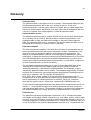
Additional information . . . . . . . . . . . . . . . . . . . . . . . . . . . . . . . . . . . . . . . . . . . . . . . . . . . . . . . . . 55
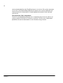
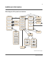
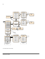
State d agram of the panel user nterface . . . . . . . . . . . . . . . . . . . . . . . . . . . . . . . . . . . . . . . . . . . . 55
Dr ve rat ngs table . . . . . . . . . . . . . . . . . . . . . . . . . . . . . . . . . . . . . . . . . . . . . . . . . . . . . . . . . . . . . . 57
บริษัท ที.จี. คอนโทรล จำกัด
1683 ทาวน์อินทาวน์ ซอย 9 แขวงพลับพลา เขตวังทองหลาง กรุงเทพฯ 10310
โทร. 02-530-9090 แฟกซ์. 02-530-9933 www.tgcontrol.com, www.facebook.com/tgcontrol
8
บริษัท ที.จี. คอนโทรล จำกัด
1683 ทาวน์อินทาวน์ ซอย 9 แขวงพลับพลา เขตวังทองหลาง กรุงเทพฯ 10310
โทร. 02-530-9090 แฟกซ์. 02-530-9933 www.tgcontrol.com, www.facebook.com/tgcontrol
9
About the manual
What this chapter contains
Th s chapter conta ns nformat on about ntended aud ence of th s manual and where
the user can get add t onal nformat on, product and serv ce nqu r es, product
tra n ng and prov de feedback on th s manual.
Intended audience
The manual s ntended for persons us ng the FlashDrop. Read t before use.
The manual s wr tten for readers worldw de. Both SI and mper al un ts are shown.
Additional information for users
Please v s t at FlashDrop product page for more nformat on about FlashDrop.
• Go to the s te http://www.abb.com w th your Internet browser
• Select Our offer ngs: ABB Product Gu de
• -> Motors, Dr ves and Power Electron cs: Dr ves
• -> Low Voltage AC Dr ves: e ther Component dr ves or General Mach nery dr ves
or Standard dr ves
• Select FlashDrop under the L nks t tle
There you w ll also f nd l nks to FlashDrop product tra n ng.
Product training
For nformat on on ABB product tra n ng, nav gate to www.abb.com/dr ves and select
Drives - Training courses on the r ght pane.
Product and service inquiries
Address any nqu r es about the product to your local ABB representat ve, quot ng
the type code and ser al number of the un t n quest on. A l st ng of ABB sales,
support and serv ce contacts can be found by nav gat ng to www.abb.com/dr ves and
select ng Drives - World wide service contacts on the r ght pane.
Providing feedback on ABB Drives manuals
Your comments on our manuals are welcome. Go to www.abb.com/dr ves, then
select success vely Drives - Document Library - Manuals feedback form on the r ght
pane.
About the manual
10
About the manual
11
Getting started
What this chapter contains
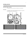
The chapter descr bes the construct on and nstallat on of the FlashDrop.
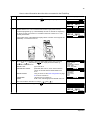
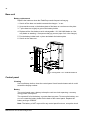
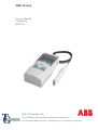
Overview
The FlashDrop s a dev ce used to ed t parameter values and v s b l ty and for
copy ng parameters fast to unpowered dr ves.
8
8
10
9
1
1
11
7
2
12
6
13
3
5
3
14
4
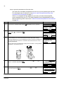
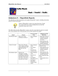
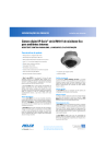
1 Base un t
8 Programm ng t p cable
2 FlashDrop Control Panel
9 Cl p for the programm ng t p cable
3 Programm ng t p
10 Battery charger connect on
4 Programm ng t p cap
11 Battery charge level nd cators (four LEDs)
5 Programm ng t p safety l ne (not prov ded)
12 Power sw tch
6 Programm ng t p cl p
13 FlashDrop Control Panel and PC connect on
7 Programm ng t p holder
14 Power OK and Fault LEDs (see LEDs on page 49)
Getting started
12
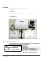
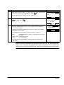
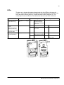
Unpacking
The del very package conta ns the follow ng tems:
• FlashDrop (1)
• PC cable (2)
• battery charger (3)
• battery charger ma ns (AC power) cable w th a set of plugs (not shown n the f
gure) (4)
• user's manual (5)
• Dr vePM CD (6).
3
2
4
6
1
5
Check that there are no s gns of damage. Not fy the sh pper mmed ately f damaged
components are found.
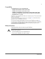
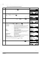
Type designation label
The type des gnat on label s attached to the back of the base un t. An example label
and explanat on of the label contents are shown below.
1 Type code
ABB Oy
2 SW version: 1.04E
lllllllllllllllllllllllllllllllllllllllllllllll
3
3 ABB MRP code
4 Ser al number of format YWWRXXXX, where
MRP code: 68566380
1 TYPE: MFDT-01
2 F rmware vers on
4 S/N: 648C0001
Type des gnat on label
Y:
5.9, A, . for 2005.2009, 2010, .
WW:
01, 02, 03, . for week 1, week 2, week 3, .
R:
A, B, C . for product rev s on number
XXXX: Integer start ng every week from 0001
Getting started
13
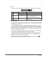
Compatibility
The FlashDrop base unit is compatible with:
• ACS1S0, drive firmware version 1.31b or later
• ACS3S0, drive firmware version 2.41a or later
• ACSSS0-01 and ACHSS0-01, drive firmware version 3.10b or later. There
needs to be a FlashDrop connector in the drive under the control panel.
• DrivePM version 1.1 or later
FlashDrop s non-compat ble w th older dr ve f rmware vers ons. The use w th older f
rmware s not allowed.
To f nd out the f rmware vers on of your dr ve, see page 27, or check the value of
parameter 3301 FW VERSION n the dr ve.
To f nd out the f rmware and hardware vers ons of your FlashDrop, see page 44.
To create and ed t FlashDrop parameter sets w th the Dr vePM PC tool or FlashDrop,
correct templates are needed. Both Dr vePM and FlashDrop templates can be
downloaded from the ABB Internet s te.
Safety instructions
Follow these safety nstruct ons when us ng the FlashDrop.
WARNING! Ignor ng the follow ng nstruct ons can cause phys cal njury or death, or
damage to the equ pment.
• Use the FlashDrop only w th an unpowered dr ve.
• Do not use the FlashDrop f the cable s broken.
Getting started
14
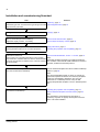
Installation and commissioning flowchart
Task
Unpack and check the un ts.
See/note
Unpacking, page 12
Check the type code nd cated on the type des gnat on label Type designation label, page 12
aga nst the or g nal order.
Charge the FlashDrop base un t.
Charging, page 15
Spec fy clock sett ngs for the FlashDrop.
How to set the date and time, page 25
Adjust the d splay contrast, f necessary.
How to adjust the display contrast, page 26
Check the compat b l ty.
Safety instructions, page 13
Check parameter table vers on and other propert es.
Checking the properties and compatibility, page 24
Install the Dr vePM tool.
How to install DrivePM tool, version 1.1 or later, page 16
Conf rm that your computer meets the m n mum system
requ rements to nstall Dr vePM tool. See Dr vePM CD-ROM
cover for requ rements or readme.txt f le n the root d rectory
of the CD-ROM.
Note:
Download the FlashDrop base un t parameter templates
from the Dr vePM to the FlashDrop.
How to download templates from the Dr vePM to FlashDrop
base un t, page 28.
Parameter templates suppl ed by Dr vePM CD-ROM are
also nstalled n ded cated Dr vePM subfolders for ACS150,
ACS350, ACS550 and ACH550 products.
Note:
The del vered FlashDrop base un t does not nclude any
parameter templates as default. The necessary templates
need to be downloaded to FlashDrop. The ed t ng of
parameter set n FlashDrop base un t requ res that
appropr ate parameter template s saved n FlashDrop base
un t.
If necessary, download templates from the Internet and
download to the FlashDrop.
Checking the properties and compatibility, page 24
How to download templates from the Internet, page 28.
Note:
The download ng of templates from the Internet s
necessary only when an appropr ate template cannot be
found n Dr vePM subfolder.
Getting started
15
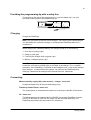
Providing the programming tip with a safety line
To avo d los ng the cap of the programm ng t p, you can attach a th n l ne (not
prov ded) to the eyelets of the programm ng t p.
Charging
Charge the FlashDrop.
Note: The l ght refers to the LED on the charger. The LEDs on the FlashDrop base
un t are always all l t when the charger s connected and FlashDrop base un t s
sw tched on.
When charg ng the FlashDrop battery, the charger operat on s the follow ng:
1. In t al zat on (orange l ght)
2. Charg ng (red l ght)
3. F nal z ng the charge (bl nk ng green l ght)
4. Battery s charged (green l ght).
Note: To charge the battery aga n, the charger must be removed from the FlashDrop
so that the n t al zat on (orange l ght) s act vated n the charger. Th s s a safety
procedure. If the FlashDrop s sw tched on and charged once, t can not be charged
aga n before t s removed from the charger. You can use the FlashDrop wh le
charg ng. Please see the charger user's manual for more nformat on.
Connecting
Mains electricity supply (AC power source) - charger - base unit
Charge the base un t w th the prov ded charger only.
FlashDrop Control Panel - base unit
The control panel s connected to the base un t w th the prov ded RJ-45 connector.
PC - base unit
To load parameter sets between the Dr vePM PC tool and the FlashDrop, connect
your PC to the base un t w th the PC cable. Use the prov ded cable only. The
FlashDrop panel has to be removed for PC connect on.
Getting started
16
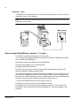
FlashDrop - drive
The FlashDrop s connected to the dr ve w th the programm ng t p. The dr ve can be
nstalled or rema n n the package.
Note: The dr ve must be d sconnected from the ma ns (AC power source) when the
FlashDrop s connected.
Main power
OFF ON
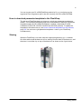
How to install DrivePM tool, version 1.1 or later
Dr vePM (Dr ve Parameter Manager) s a PC tool for
1) creat ng and ed t ng parameter sets of ACS150, ACS350, ACS550 and ACH550
to be su table for FlashDrop un t,
2) transferr ng these sets between PC and FlashDrop,
3) transferr ng template f les to FlashDrop and
4) updat ng FlashDrop f rmware.
Dr vePM s des gned to run under the M crosoft W ndows 2000 or W ndows XP
operat ng systems on IBM -compat ble PCs.
You should qu t all appl cat ons before start ng the nstallat on. Un nstall any prev ous
vers on of Dr vePM before nstall ng. You must have Adm n strator pr v leges to be
able to do the nstall ng. Before cont nu ng, k ndly remove all f les that W ndows was
not able to remove from Dr vePM d rectory and t's subd rector es.
1. Run the SETUP.EXE from the root d rectory of th s CD.
2. Follow the nstruct ons g ven by the Installat on W zard.
Dr vePM conta ns onl ne help wh ch can started by press ng 'F1' key or from the
'Help' Menu. Onl ne Help requ res MS InternetExplorer 3.0 or later nstalled n the
computer.
Getting started
17
You can reg ster your Dr vePM/FlashDrop product by f ll ng n and return ng the
reg strat on form (reg strat on.pdf n the root d rectory of the Dr vePM CD-ROM).
How to download parameter templates to the FlashDrop
The del vered FlashDrop base un t does not nclude any parameter templates as
default. The necessary templates need to be downloaded to FlashDrop. Parameter
templates suppl ed by Dr vePM CD-ROM are nstalled n ded cated Dr vePM
subfolders for ACS150, ACS350, ACS550 and ACH550 products. To update the
templates to the latest vers on, see How to download templates from the Internet,
page 28. You can have e ght parameter templates n total n your FlashDrop
s multaneously.
Storing
When the FlashDrop s not used, keep the capped programm ng t p n ts holder.
W nd the cable round the base un t tw ce, start ng from the back of the base un t, and
then tw st t round the cl p on top of the base un t as shown on the f gure below.
Getting started
18
Getting started
19
Operation
What this chapter contains
The chapter g ves a general v ew of us ng the FlashDrop w th the Dr vePM PC tool to
parameter ze dr ves. It descr bes n deta l the FlashDrop Control Panel keys and
d splay f elds and how to use the FlashDrop for the dr ve parametr zat on. The state
d agram of the panel user nterface s ncluded n Additional information, page 55.
See also Glossary, page 53.
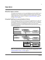
Using the FlashDrop for parametrization of drives
W th the FlashDrop, parameters can be fast cop ed to unpowered dr ves, before del
very from the warehouse or dur ng the mechan cal nstallat on at the s te. Because
the FlashDrop s used w th an unpowered dr ve, the dr ve can rema n n the package
dur ng the parametr zat on. The FlashDrop also allows you to h de selected
parameters to protect the dr ve and connected mach nery and show only nformat on
relevant to the appl cat on.
DrivePM PC tool
Template
DriveWindowlight 2
parameter file (.dwp)
FlashDrop set
FlashDrop set
FlashDrop set
Edit values
& visibility
FlashDrop
Template
FlashDrop set
FlashDrop set
FlashDrop set
Edit values
& visibility
Drive
FlashDrop set
- values
- visibility
Active
parameters
Note: The pr mary way to create and ed t parameter sets s by us ng the Dr vePM
PC tool. For nstruct ons on us ng the Dr vePM, see the Dr vePM help and How to
install DrivePM tool, version 1.1 or later, page 16.
Operation
20
Us ng the FlashDrop to download parameters to dr ves cons sts of four phases.
1. Create a FlashDrop parameter set w th the Dr vePM from a template or
a Dr veW ndowL ght parameter f le. The name and author n the header
nformat on can be ed ted. See the Dr vePM help.
or
Create a FlashDrop parameter set w th the FlashDrop Control Panel from a
template. The header nformat on of the set conta ns data about the set, nclud ng
ID, name, author and creat on t me. The nformat on s generated automat cally.
See How to initialize (create) a parameter set on page 30.
or
Upload a parameter set from the dr ve to the FlashDrop. The header nformat on s
generated automat cally. See How to upload a parameter set from the drive on
page 32.
2. Ed t the set w th the FlashDrop Control Panel by g v ng values to parameters and
sett ng v s b l t es of parameters and parameter groups. See How to edit a
parameter set on page 35.
or
Ed t the set w th the Dr vePM by g v ng values to parameters and sett ng
v s b l t es of parameters and parameter groups. Then download the set to the
FlashDrop (FlashDrop menu -> Download To FD). You can cont nue ed t ng w th
the FlashDrop Control Panel f necessary. See the Dr vePM help.
3. Download the set from the FlashDrop to one or more unpowered dr ves. Ensure
that the dr ve s d sconnected from the ma ns (AC power source). See How to
download a parameter set to a drive on page 43.
4. Power up the dr ve to act vate the downloaded parameter values and v s b l t es.
See also the flowchart of the dr ve parametr zat on w th the FlashDrop on page 21.
Note: Also parameters 9902 APPLIC MACRO and 1611 PARAMETER VIEW can be
made nv s ble n a FlashDrop parameter set. After the set has been downloaded to a
dr ve and act vated, to be able to change these parameters n the dr ve, e.g. to use a
macro, you have to f rst make them v s ble w th the FlashDrop. Upload the set from
the dr ve to the FlashDrop, make parameters 9902 APPLIC MACRO and
1611 PARAMETER VIEW v s ble, and then download the set aga n to the dr ve. You
can sw tch the dr ve to use other parameter sets (macros) w th parameter
9902 APPLIC MACRO. To react vate the parameter values def ned by the
downloaded FlashDrop parameter set, set parameter 9902 to value
31 (FD PAR SET). You can sw tch the dr ve to use the default v s b l t es of the
parameters and parameter groups by sett ng parameter 1611 PARAMETER VIEW to
value 0 (DEFAULT). To react vate the v s b l t es def ned by the downloaded
FlashDrop parameter set, set parameter 1611 to value 1 (FLASHDROP).
Operation
21
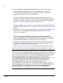
FlashDrop parametrization flowchart
Task in ...
DrivePM (PC)
Create a set from a
template or a
Dr veW ndowL ght
parameter f le.
Convert the parameter set
the same as n the target
dr ve.
FlashDrop
Upload a set from a dr ve.
See How to upload a
parameter set from the
drive on page 32.
No
Yes
Create a set from a
template. See How to
initialize (create) a
parameter set on page
30.
Is the parameter table vers
on the same as n target dr
ve? See How to view
information about the drive
connected to the
FlashDrop on page 27.
Ed t the name and author
n the set header
nformat on.
Ed t parameter values &
parameter and
parameter group
v s b l t es.
Download the set to the
FlashDrop. FlashDrop
menu -> Download To
FD. See Dr vePM
Help.
Ed t parameter values & parameter and parameter
group v s b l t es. See How to edit a parameter set
on page 35.
Download the set to an unpowered dr ve. See How to
download a parameter set to a drive on page 43.
Power up the dr ve.
Operation
22
FlashDrop Control Panel and its operation
The FlashDrop Control Panel s the user nterface for us ng the FlashDrop.
Note: It s not poss ble to use the FlashDrop Control Panel as the control panel for
the dr ve.
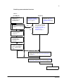
Control panel overview
The follow ng table summar zes the key funct ons and d splays n the FlashDrop
Control Panel.
No. Use
1
2a NC
MAIN MENU
PARAMETERS
2b TIME & DATE
DRIVE INFO
2c
OO:OO
3
5
7
9
6
1
Status LED - See LEDs on page 49.
2
LCD d splay - D v ded nto three ma n areas:
1
a. Status l ne - var able, depend ng on the mode of operat on, see Status line
on page 23.
b. Center - var able; n general, shows parameter values, menus or l sts.
c. Bottom l ne - shows current funct ons of the two soft keys and, f enabled,
the clock d splay.
SELECT
3
Soft key 1 - Funct on depends on the context. The text n the lower left corner
of the LCD d splay nd cates the funct on.
4
Soft key 2 - Funct on depends on the context. The text n the lower r ght
corner of the LCD d splay nd cates the funct on.
5
Up • Scrolls up through a menu or l st d splayed n the center of the LCD d splay.
• Increments a value f a parameter s selected.
Hold ng the key down changes the value faster.
6
Down • Scrolls down through a menu or l st d splayed n the center of the LCD
d splay.
• Decrements a value f a parameter s selected.
Hold ng the key down changes the value faster.
7
LOC/REM - Not used.
8
Help - D splays context sens t ve nformat on when the key s pressed n the
parameter menu. The nformat on d splayed descr bes the parameter currently
h ghl ghted n the center of the d splay.
9
STOP - Not used.
4
8
10
10 START - Downloads the selected set when you are n the set select on
d splay (SET SELECT shown on the status l ne) or n the Set act on menu
(SET ACTIONS shown on the status l ne), see How to download a parameter
set to a drive on page 43.
Operation
23
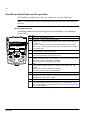
Status line
The top l ne of the LCD d splay shows the bas c status nformat on of the FlashDrop.
NC
1
No. Field
Alternatives
1 Dr ve connect on NC
DRV
2 Panel operat on
mode
MAIN MENU
2
1
3
Significance
Not connected to a dr ve.
Connected to a dr ve.
• Name of the current mode
• Name of the l st or menu shown
• Name of the operat on state, e.g. PAR EDIT.
3 Number of the
selected tem
Number of the h ghl ghted tem, e.g mode or
parameter group.
Operation principles
You operate the control panel w th the help of menus and keys. The keys nclude two
context-sens t ve soft keys, whose current funct on s nd cated by the text shown n
the d splay above each key.
You select an opt on, e.g. operat on mode or parameter, by scroll ng the
and
arrow keys unt l the opt on s h ghl ghted ( n reverse v deo) and then press ng
the relevant soft key. W th the r ght soft key you usually enter a mode, accept an opt
on or save the changes. The left soft key s used to cancel the made changes and
return to the prev ous operat on level.
The control panel has the follow ng panel modes: Parameters, T me & Date and Info.
The operat on n the d fferent modes s descr bed n th s chapter.
In t ally, the control panel s n the Ma n menu, where you select the appropr ate
mode for your task. The status l ne (see sect on Status line on page 23) shows the
name of the current menu, mode, tem or state.
When an error occurs, the control panel shows the error message. Press
reset. For more nformat on, see chapter Fault tracing.
OK
to
Operation
24
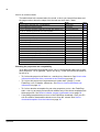
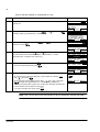
How to do common tasks
The table below l sts common tasks, the mode n wh ch you can perform them and
the page number where the steps to do the task are descr bed n deta l.
Task
Mode
How to set the date and t me n the FlashDrop
T me & Date
Page
25
How to adjust the d splay contrast
Ma n menu
26
How to check the parameter table vers ons and other propert es of
the dr ve, FlashDrop parameter sets and templates
Info and Parameters
24
How to v ew nformat on about the dr ve connected to the FlashDrop Info
27
How to download templates from the Internet
Dr vePM (PC)
28
How to n t al ze (create) a parameter set
Parameters
30
How to upload a parameter set from the dr ve
Parameters
32
How to v ew the parameter set nformat on
Parameters
34
How to ed t a parameter set
Parameters
35
How to ed t the value of a parameter
Parameters
36
How to v ew and ed t the values of changed parameters
Parameters
38
How to ed t the v s b l ty of a parameter
Parameters
40
How to ed t the v s b l ty of a parameter group
Parameters
41
How to clear (delete) a parameter set
Parameters
42
How to download a parameter set to a dr ve
Parameters
43
How to v ew nformat on about the FlashDrop
Info
44
How to f nd out the control panel vers on
At power up
44
Checking the properties and compatibility
To be able to download a parameter set to a dr ve, the parameter table vers on and
other propert es - dr ve type and, f spec f ed, rat ng - of the set must be the same as
for the dr ve.
• To f nd out the propert es of the dr ve, v ew the dr ve nformat on. See How to view
information about the drive connected to the FlashDrop on page 27.
• To f nd out the propert es of a parameter set (other than "[ empty ]") n the
FlashDrop, v ew ts header nformat on. See How to view the parameter set
information on page 34.
• To f nd out whether a template for part cular propert es ex sts n the FlashDrop,
start n t al z ng an empty set and check whether any of the shown templates has
these propert es. See How to initialize (create) a parameter set on page 30.
• If a su table template does not ex st n the FlashDrop, download t from your PC
w th Dr vePM or download the latest vers on from the nternet. See How to
download templates from the Internet on page 28.
Operation
25
Time & Date mode
In the T me & Date mode, you can spec fy clock sett ngs for the FlashDrop.
The control panel conta ns a battery to ensure the funct on of the clock when the
control panel s not powered by the base un t.
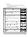
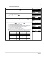
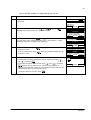
How to set the date and time
Step
1.
Action
If you are not n the Ma n menu, press
Display
EXIT
repeatedly unt l you get there.
NC
MAIN MENU
PARAMETERS
TIME & DATE
DRIVE INFO
OO:OO
1
SELECT
2.
Go to the T me & Date mode by select ng TIME & DATE on the menu w th keys
SELECT
and
, and press ng
.
NC
TIME & DATE
1
CLOCK VISIBILITY
TIME FORMAT
DATE FORMAT
SET TIME
SET DATE
EXIT
OO:OO SELECT
3.
• To set the v s b l ty of the clock on the bottom l ne of the LCD d splay, select
SELECT
CLOCK VISIBILITY on the menu and press
. Select the preferred sett ng
SELECT
w th keys
and
, and press
.
NC
CLOCK VISIB
Show clock
Hide clock
CANCEL
• To set the t me format of the clock, select TIME FORMAT on the menu and
SELECT
press
. Select the preferred sett ng w th keys
and
, and
SELECT
press
.
NC
TIME FORMAT
24-hour
12-hour
CANCEL
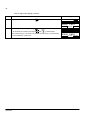
• To set the format of the date, select DATE FORMAT on the menu and press
SELECT
. dd means the day, mm the month and yy or yyyy the year. Select the
OK
preferred sett ng w th keys
and
, and press
.
• To set the t me, select SET TIME on the menu and press
. Spec fy the
OK
hours w th keys
and
, and press
.Then spec fy the m nutes.
OK
CANCEL
Press
to save or
to cancel your changes.
NC
• To set the date, select SET DATE on the menu and press
. Spec fy the
f rst part of the date (day or month depend ng on the date format) w th keys
OK
and
, and press
. Repeat for the second part. After
OK
CANCEL
spec fy ng the year, press
. To cancel your changes, press
.
15:41
NC
OO:OO
OK
SET DATE
19.O3. O6
CANCEL
• To set the used dayl ght sav ng, select DAYLIGHT SAVING on the menu and
SELECT
press
. Select your area or off w th keys
and
, and press
SELECT
.
OK
OO:OO
SET TIME
CANCEL
SELECT
SELECT
OO:OO
NC
TIME FORMAT
dd.mm.yy
mm/dd/yy
dd.mm.yyyy
mm/dd/yyyy
CANCEL
SELECT
SELECT
OO:OO
OO:OO
OK
NC
TIME FORMAT
Off
EU US
Australia1:NSW,Vict..
Australia2:Tasmania..
CANCEL
OO:OO
SELECT
Operation
26
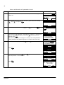
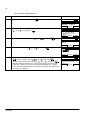
How to adjust the display contrast
Step
1.
Action
Display
EXIT
If you are not n the Ma n menu, press
repeatedly unt l you get there.
NC
MAIN MENU
PARAMETERS
TIME & DATE
DRIVE INFO
OO:OO
2.
• To ncrease the contrast, press keys
SELECT
• To decrease the contrast, press keys
and
SELECT
and
s multaneously.
s multaneously.
The contrast sett ng s not saved. The default contrast sett ng s resumed each
t me the FlashDrop s started up.
Operation
1
NC
SELECT
MAIN MENU
1
PARAMETERS
TIME & DATE
DRIVE INFO
OO:OO
SELECT
27
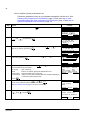
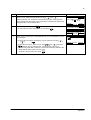
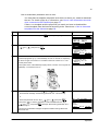
How to view information about the drive connected to the FlashDrop
Step
1.
Action
Display
EXIT
If you are not n the Ma n menu, press
repeatedly unt l you get there.
NC
MAIN MENU
PARAMETERS
TIME & DATE
DRIVE INFO
SELECT
OO:OO
2.
Ensure that the dr ve s d sconnected from the ma ns (AC power source).
Insert the programm ng t p n the FlashDrop connect on of the dr ve. Depend ng
on the dr ve type, the connect on s located on the front of the dr ve or n the
control panel recess.
DRV
Go to the Dr ve Info mode by select ng DRIVE INFO on the menu w th keys
SELECT
and
, and press ng
. The d splay shows the follow ng
nformat on about the dr ve:
DRIVE TYPE:
PARAMETER TABLE:
DRIVE RATING:
FIRMWARE:
AREA:
type of the dr ve
parameter table vers on, wh ch must match the
vers on of the sets that are downloaded to the
dr ve.
rat ng of the dr ve. See Drive ratings table on page
57 for more nformat on.
f rmware vers on of the dr ve
EUR or US, selects appropr ate defaults and un ts
You can scroll the nformat on w th keys
4.
Return to the Ma n menu by press ng
EXIT
and
.
MAIN MENU
1
PARAMETERS
TIME & DATE
DRIVE INFO
SELECT
OO:OO
The top left corner of the FlashDrop d splay shows now DRV nd cat ng that the
FlashDrop s connected to a dr ve.
3.
1
DRV
DRIVE INFO
DRIVE TYPE:
ACS35O
PARAMETER TABLE:
241A hex
DRIVE RATING:
EXIT
OO:OO
DRV
DRIVE INFO
2A41 hex
FIRMWARE:
241A hex
AREA:
EUR
EXIT
OO:OO
.
DRV
MAIN MENU
PARAMETERS
TIME & DATE
DRIVE INFO
OO:OO
1
SELECT
Operation
28
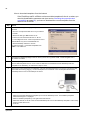
How to download templates from the Internet
If the FlashDrop and Dr vePM do not have su table templates for the dr ve where you
ntend to download the parameter set (see sect on Checking the properties and
compatibility on page 24), you have to download the correct templates from the
Internet w th Dr vePM.
Step
1.
Action
Go to the FlashDrop product page w th your Internet
Browser:
• Go to the s te http://www.abb.com w th your Internet
browser
• Select Our offer ngs: ABB Product Gu de
-> Motors, Dr ves and Power Electron cs: Dr ves
-> Low Voltage AC Dr ves: e ther Component dr ves or
General Mach nery dr ves or Standard dr ves
• Select FlashDrop under the L nks t tle
Or select F le menu -> Download Templates from
ABB. n Dr vePM tool.
2.
Download the template package to the PC where you are runn ng the Dr vePM, n folder Program F les /
Dr veWare / Dr vePM.
3.
Extract the package.
The Dr vePM templates are now v s ble n the Dr vePM PC tool. Download next the FlashDrop base un t
templates to the FlashDrop, as nstructed n steps 4. and 5.
4.
Remove the control panel from the FlashDrop. Connect the Flash Drop base un t to the PC w th the prov ded
data cable OPCA-02 by plugg ng t to the control panel / PC connect on n the control panel recess of the
FlashDrop base un t and to the COM port of the PC.
5.
Download the FlashDrop base un t templates from the Dr vePM to the FlashDrop:
• Select the Download FlashDrop Template opt on from the FlashDrop menu. The FlashDrop Template
Download d alog box s d splayed.
• Select a FlashDrop template by cl ck ng Browse under Source.
• Select the dest nat on f le set of the connected FlashDrop dev ce from the FlashDrop Template Locat on dropdown l st under Dest nat on.
• Cl ck OK.
Operation
29
Parameters mode
In the Parameters mode, you can:
• download a parameter set to a dr ve
•
n t al ze (create) a parameter set
• upload a parameter set from the dr ve
• v ew the header nformat on of a parameter set
• ed t a parameter set
• ed t values of parameters for the act ve parameter set
• ed t values of parameters for the user sets (user set1-3 and overr de set)
• v ew and ed t values of changed parameters n the set
• ed t the v s b l t es of parameters n the set
• ed t the v s b l t es of whole parameter groups n the set
• clear (delete) a parameter set.
Operation
30
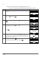
How to initialize (create) a parameter set
Create the parameter set by us ng a template compat ble w th the dr ve. See
Checking the properties and compatibility, page 24. See also How to view
information about the drive connected to the FlashDrop, page 27 and How to
download templates from the Internet, page 28.
Step
1.
Action
Display
If you are not n the Ma n menu, press
EXIT
repeatedly unt l you get there.
NC
MAIN MENU
1
PARAMETERS
TIME & DATE
DRIVE INFO
OO:OO
SELECT
2.
Go to the Parameters mode by select ng PARAMETERS on the menu w th keys
SELECT
and
, and press ng
.
NC
SETS
1
1. Demo
2. Varying speed
3. 2 Cycles DI2
FlashDrop set O4
[ empty ]
EXIT
OO:OO SELECT
3.
Select an empty set ("[ empty ]") on the menu w th keys
INIT
start ts n t al zat on by press ng
.
NC
SETS
5
2. Varying speed
3. 2 Cycles DI2
FlashDrop set O4
[ empty ]
6. Traverse Ctrl
EXIT
INIT
OO:OO
4.
Select "Create a new set" on the menu w th keys
SELECT
cont nue by press ng
.
and
and
, and
, and
NC
5
Select init mode
Create a new set
Upload from drive
CANCEL
5.
Select the appropr ate template w th keys
each template are shown below t:
Dr ve type:
Area:
Param table:
Control mode:
Press
6.
and
. The propert es of
type of the dr ve
EUR or US, selects appropr ate defaults and un ts
parameter table vers on of the set.
scalar or vector mode. All parameter sets created by FlashDrop
w ll have the same control mode.
SELECT
.
Select the dr ve rat ng w th keys
and
f the set parameters depend
SELECT
on the rat ng, otherw se select "Not def ned". Press
.
See Drive ratings table on page 57 for more nformat on.
Select the default v s b l ty for parameters and parameter groups w th keys
SELECT
and
. Press
.
NC
SET INIT
Drive rating
2A42
NC
OO:OO
SELECT
SET INIT
Select visibility
Visible as default
CANCEL
Operation
SELECT
NC
SET INIT
Select Template
O1
Drive type:
ACS35O
Area:
EUR
Param table: 2 3OA
Control mode:S CALAR
CANCEL OO:OO SELECT
CANCEL
7.
OO:OO
OO:OO
SELECT
31
Step
8.
Action
Message "Sav ng parameter set" s shown. If the sav ng succeeds, the panel
LED s green for a moment and message "Set save OK" s shown br efly.
The FlashDrop ass gns automat cally the follow ng header nformat on to the
set:
Name:
FLASHDROP SET nn, where nn s the ndex of the set n the
FlashDrop
T me and date: current t me and date
Author:
text "FLASHDROP".
Display
NC
SET SELECT
5
2. Varying speed
3. 2 Cycles DI2
FLASHDROP SET O4
FLASHDROP SET O5
6. Traverse Ctrl
EXIT
OO:OO SELECT
The panel returns to the set select on d splay and shows the name of the
n t al zed set.
Operation
32
How to upload a parameter set from the drive
You must have a template compat ble w th the dr ve you are upload ng the set from.
For check ng the dr ve nformat on, see How to view information about the drive
connected to the FlashDrop on page 27.
If there s no template w th the propert es you need, you have to download the
correct template from your PC. The latest templates can be downloaded from the
Internet accord ng to the nstruct ons n How to download templates from the Internet
on page 28.
Step
1.
Action
If you are not n the Ma n menu, press
Display
EXIT
repeatedly unt l you get there.
NC
MAIN MENU
1
PARAMETERS
TIME & DATE
DRIVE INFO
OO:OO
SELECT
2.
Go to the Parameters mode by select ng PARAMETERS on the menu w th keys
SELECT
and
, and press ng
.
NC
SETS
1
1. Demo
2. Varying speed
3. 2 Cycles DI2
FlashDrop set O4
[ empty ]
EXIT
OO:OO SELECT
3.
Ensure that the dr ve s d sconnected from the ma ns (AC power source).
DRV
SETS
1
1. Demo
2. Varying speed
3. 2 Cycles DI2
FlashDrop set O4
[ empty ]
EXIT
OO:OO SELECT
Insert the programm ng t p n the FlashDrop connect on of the dr ve. Depend ng
on the dr ve type, the connect on s located on the front of the dr ve or n the
control panel recess.
The top left corner of the FlashDrop d splay shows now DRV nd cat ng that the
FlashDrop s connected to a dr ve.
4.
Select an empty set ("[ empty ]") on the menu w th keys
INIT
.
start ts n t al zat on by press ng
5.
Select "Upload from dr ve" on the menu w th keys
SELECT
cont nue by press ng
.
and
and
, and
, and
DRV
SETS
5
2. Varying speed
3. 2 Cycles DI2
FlashDrop set O4
[ empty ]
6. Traverse Ctrl
EXIT
INIT
OO:OO
DRV
5
Select init mode
Create a new set
Upload from drive
CANCEL
Operation
OO:OO
SELECT
33
Step
6.
Action
Display
Select the dr ve rat ng w th keys
and
f the set parameters depend
SELECT
on the rat ng, otherw se select "Not def ned". Press
.
See Drive ratings table on page 57 for more nformat on.
DRV
UPLOAD SET
Drive rating
2A42
CANCEL
7.
Select the default v s b l ty for parameters and parameter groups w th keys
SELECT
and
. Press
.
DRV
UPLOAD SET
Select visibility
Visible
CANCEL OO:OO
8.
Message "Upload ng parameter set" s shown. Control modes of the user sets
w ll be cop ed from the dr ve. If a user set s empty the control mode of the
act ve set w ll be appl ed.
If the sav ng succeeds, the panel LED s green for a moment and message
"Upload OK" s shown br efly.
SELECT
OO:OO
SELECT
DRV
SETS
5
2. Varying speed
3. 2 Cycles DI2
FLASHDROP SET O4
FLASHDROP SET O5
6. Traverse Ctrl
EXIT
OO:OO SELECT
The FlashDrop ass gns the follow ng header nformat on to the set:
Name:
FLASHDROP SET nn, where nn s the ndex of the set n the
FlashDrop
T me and date: current t me and date
Author:
text "FLASHDROP".
The panel returns to the set select on d splay and shows the name of the
n t al zed set.
Note: You can only download the uploaded set to a dr ve w th the same parameter
table vers on. Otherw se the uploaded set must be converted to a correct parameter
table vers on us ng the Dr vePM PC tool. See the Dr vePM help for more nformat on.
Operation
34
How to view the parameter set information
Step
1.
Action
If you are not n the Ma n menu, press
Display
EXIT
repeatedly unt l you get there.
NC
MAIN MENU
PARAMETERS
TIME & DATE
DRIVE INFO
OO:OO
2.
Go to the Parameters mode by select ng PARAMETERS on the menu w th keys
SELECT
and
, and press ng
.
3.
Select the parameter set w th keys
and
, and press
SELECT
.
4.
Select INFO w th keys
and
, and press
the follow ng nformat on about the parameter set:
. The d splay shows
SET INDEX:
SET NAME
ndex of the set n the FlashDrop
name of the set, free text ed ted n the Dr vePM or
created automat cally when n t al zed n the
FlashDrop (of format "FlashDrop set nn", where nn
s the set ndex)
TIME:
creat on t me of the set
DATE:
creat on date of the set
AUTHOR:
creator of the set, free text ed ted n the Dr vePM or
created automat cally when n t al zed n the
FlashDrop ("FlashDrop")
DRIVE RATING:
rat ng of the dr ve
DRIVE TYPE:
type of the dr ve
AREA:
EUR or US, selects appropr ate defaults and un ts
CONTROL MODE:
scalar or vector mode
PARAMETER TABLE VER parameter table vers on of the set.
You can scroll the nformat on w th keys
5.
and
.
After read ng the text, return to the prev ous d splay by press ng
EXIT
.
NC
SET ACTIONS
DOWNLOAD
INFO
EDIT
DELETE
OO:OO
1
SELECT
NC
PAR SET INFO
SET INDEX:
4
SET NAME:
FlashDrop set O4
TIME:
EXIT
OO:OO
NC
PAR SET INFO
12:23:5O
DATE:
12.O3.2OO6
AUTHOR:
FlashDrop
EXIT
OO:OO
NC
PAR SET INFO
DRIVE RATING:
2A42
DRIVE TYPE:
ACS35O
AREA:
EXIT
OO:OO
NC
PAR SET INFO
EUR
CONTROL MODE:
SCALAR
PARAMETER TABLE VE R:
23OA
EXIT
OO:OO
NC
SET ACTIONS
DOWNLOAD
INFO
EDIT
DELETE
EXIT
Operation
SELECT
NC
SETS
1
1. Demo
2. Varying speed
3. 2 Cycles DI2
FlashDrop set O4
[ empty ]
EXIT
OO:OO SELECT
EXIT
SELECT
1
OO:OO
2
SELECT
35
How to edit a parameter set
Step
1.
Action
Display
If you are not n the Ma n menu, press
EXIT
repeatedly unt l you get there.
NC
MAIN MENU
PARAMETERS
TIME & DATE
DRIVE INFO
SELECT
OO:OO
2.
Go to the Parameters mode by select ng PARAMETERS on the menu w th keys
SELECT
and
, and press ng
.
3.
Select the parameter set w th keys
and
, and press
SELECT
.
NC
SETS
1
1. Demo
2. Varying speed
3. 2 Cycles DI2
FlashDrop set O4
[ empty ]
EXIT
OO:OO SELECT
NC
SET ACTIONS
DOWNLOAD
INFO
EDIT
DELETE
EXIT
4.
Select EDIT w th keys
and
, and press
SELECT
.
• To ed t the values of parameters, see page 36.
• To ed t the values of parameters whose values have been changed before
(us ng a l st that shows changed parameters only), see page 38.
• To ed t the v s b l ty of parameters, see page 40.
Note: The v s ble menu cho ces depends on the type of the dr ve to wh ch the
set s for. See the follow ng table for a l st of the sets supported by the dr ves
ACS1S0
ACS3S0
ACSSS0
ACHSS0
X
X
X
X
User set 1
X
X
X
User set 2
X
X
X
User set 3
X
Active parameters
Override set
1
SELECT
OO:OO
NC
EDIT MENU
1
ACTIVE SET
PARAMETER VISIBILITY
GROUP VISIBILITY
USER SET1
USER SET2
EXIT
OO:OO SELECT
NC
EDIT MENU
USER SET3
OVERRIDE SET
• To ed t the v s b l ty of parameter groups, see page 41.
1
EXIT
OO:OO
6
SELECT
X
Operation
36
How to edit the value of a parameter in a set
Step
Action
Display
1.
If you are not n the Ed t menu, see How to edit a parameter set on page 35 for
nstruct ons.
NC
EDIT MENU
1
ACTIVE SET
PARAMETER VISIBILITY
GROUP VISIBILITY
USER SET1
USER SET2
EXIT
OO:OO SELECT
2.
Select the set (act ve set, user set1, user set2 .) you want to ed t w th keys
SELECT
and
, and press
.
NC
EDIT MENU
PARAMETERS
CHANGED PARAMETERS
CANCEL
3.
Select the PARAMETERS w th keys
and
, and press
SELECT
.
OO:OO
NC
Show hidden?
No
Yes
CANCEL OO:OO
4.
If you want to see all parameters n the FlashDrop wh le ed t ng, nclud ng those
that are h dden n the set, select Yes w th key
, otherw se leave No
ENTER
selected. Press
.
Note: Select ng Yes does not change the v s b l ty of the h dden parameters.
H dden parameters and parameter groups are nd cated w th an aster sk (*).
5.
Select the parameter group w th keys
Press
6.
.
.
EDIT
.
ENTER
NC
GROUPS
O1
O1 OPERATING DATA
O3*FB ACTUAL SIGNALS
O4 FAULT HISTORY
1O START/STOP/DIR
11 REFERENCE SELECT
EXIT
OO:OO SELECT
NC
GROUPS
12
O4 FAULT HISTORY
1O START/STOP/DIR
11 REFERENCE SELECT
12 CONSTANT SPEEDS
13 ANALOGUE INPUTS
EXIT
OO:OO SELECT
NC
PARAMETERS
12O1 CONST SPEED SEL
DI3,4
12O2 CONST SPEED 1
12O3 CONST SPEED 2
12O4 CONST SPEED 3
EXIT
EDIT
OO:OO
SELECT
Select the parameter w th keys
and
selected parameter s shown below t.
Press
and
SELECT
. The current value of the
NC
PARAMETERS
12O1 CONST SPEED SEL
12O2 CONST SPEED 1
5.O Hz
12O3 CONST SPEED 2
12O4 CONST SPEED 3
EXIT
EDIT
OO:OO
NC
PAR EDIT
12O2 CONST SPE ED 1
5.O H z
CANCEL
Operation
OO:OO
SAVE
37
Step
7.
Action
Display
Spec fy a new value for the parameter w th keys
and
.
Press ng the key once ncrements or decrements the value. Hold ng the key
down changes the value faster. Press ng the keys s multaneously replaces the
d splayed value w th the default value.
8.
• To save the new value, press
SAVE
.
• To cancel the new value and keep the or g nal, press
9.
CANCEL
.
When you ex t the Ed t menu of the parameter set, you are requested to conf rm
your changes.
• To cancel the new values and keep the or g nal, select No w th keys
• To save the new values, select Yes w th keys
and
, and press
ENTER
. Message "Sav ng parameter set" s shown br efly. If the sav ng
succeeds, the panel LED s green for a moment and message "Set save OK"
s shown before return ng the ma n Ed t menu.
• To return to the prev ous menu, press
NC
PAR EDIT
12O2 CONST SPE ED 1
5.5 H z
CANCEL
OO:OO
SAVE
NC
PARAMETERS
12O1 CONST SPEED SEL
12O2 CONST SPEED 1
5.5 Hz
12O3 CONST SPEED 2
12O4 CONST SPEED 3
EXIT
EDIT
OO:OO
NC
Confirm changes?
No
Yes
CANCEL OO:OO
ENTER
CANCEL
.
Operation
38
How to view and edit the values of changed parameters in a set
Th s opt on s a shortcut to those parameters that have already been mod f ed.
Step
Action
Display
1.
If you are not n the Ed t menu, see How to edit a parameter set on page 35 for
nstruct ons.
NC
EDIT MENU
1
ACTIVE SET
PARAMETER VISIBILITY
GROUP VISIBILITY
USER SET1
USER SET2
EXIT
OO:OO SELECT
2.
Select the set (act ve set, user set1, user set2 .) you want to ed t w th keys
SELECT
and
, and press
.
NC
EDIT MENU
PARAMETER
CHANGED PARAMETERS
CANCEL
3.
Select CHANGED PARAMETERS w th keys
SELECT
.
4.
Select the parameter w th keys
and
selected parameter s shown below t.
Press
EDIT
and
, and press
. The current value of the
SELECT
NC
CHANGED PARS
12O1 CONST SPEED SEL
DI3,4
12O2 CONST SPEED 1
13O1 MINIMUM AI1
13O2 MAXIMUM AI1
EXIT
EDIT
OO:OO
NC
CHANGED PARS
12O1 CONST SPEED S EL
12O2 CONST SPEED 1
5.5 Hz
13O1 MINIMUM AI1
13O2 MAXIMUM AI1
EXIT
EDIT
OO:OO
NC
.
OO:OO
PAR EDIT
12O2 CONST SPE ED 1
5.5 H z
CANCEL
5.
Spec fy a new value for the parameter w th keys
and
.
Press ng the key once ncrements or decrements the value. Hold ng the key
down changes the value faster. Press ng the keys s multaneously replaces the
d splayed value w th the default value.
6.
• To save the new value, press
SAVE
.
• To cancel the new value and keep the or g nal, press
Operation
CANCEL
.
NC
OO:OO
SAVE
PAR EDIT
12O2 CONST SPE ED 1
5.8 H z
CANCEL
OO:OO
SAVE
NC
CHANGED PARS
12O2 CONST SPEED 1
5.8 Hz
13O1 MINIMUM AI1
13O2 MAXIMUM AI1
14O1 RELAY OUTPUT
EXIT
EDIT
OO:OO
39
Step
7.
Action
Display
When you ex t the Ed t menu of the parameter set, you are requested to conf rm
your changes.
• To cancel the new values and keep the or g nal, select No w th keys
• To save the new values, select Yes w th keys
and
, and press
ENTER
. Message "Sav ng parameter set" s shown br efly. If the sav ng
succeeds, the panel LED s green for a moment and message "Set save OK"
s shown before return ng to the ma n Ed t menu.
• To return to the prev ous menu, press
NC
Confirm changes?
No
Yes
CANCEL OO:OO
ENTER
CANCEL
.
Operation
40
How to edit the visibility of a parameter in a set
Step
Action
Display
1.
If you are not n the Ed t menu, see How to edit a parameter set on page 35 for
nstruct ons.
2.
Select PARAMETER VISIBILITY w th keys
and
Message "Open ng parameter set" s shown br efly.
3.
Select the parameter group w th keys
SELECT
are shown. Press
.
4.
Select the parameter w th keys
and
. The current v s b l ty
(V s ble/H dden) of the selected parameter s shown below t. H dden
parameters are nd cated w th an aster sk (*).
5.
• To h de a v s ble parameter, press
HIDE
• To show a h dden parameter, press
6.
and
, and press
SELECT
.
. Only v s ble groups
.
When you ex t the Groups menu, you are requested to conf rm your changes.
• To cancel the new values and keep the or g nal, select No w th keys
ENTER
and
, and press
.
• To save the new values, select Yes w th keys
and
, and press
ENTER
. Message "Sav ng parameter set" s shown br efly. If the sav ng
succeeds, the panel LED s green for a moment and message "Set save OK"
s shown before return ng the ma n Ed t menu.
• To return to the prev ous menu, press
NC
GROUPS
O1
O1 OPERATING DATA
O4 FAULT HISTORY
1O START/STOP/DIR
11 REFERENCE SELECT
12 CONSTANT SPEEDS
EXIT
OO:OO SELECT
NC
PARAMETERS
12O1 CONST SPEED SEL
Visible
12O2 CONST SPEED 1
12O3 CONST SPEED 2
12O4*CONST SPEED 3
EXIT
HIDE
OO:OO
NC
PARAMETERS
12O1 CONST SPEED SEL
12O2 CONST SPEED 1
Visible
12O3 CONST SPEED 2
12O4*CONST SPEED 3
EXIT
HIDE
OO:OO
NC
PARAMETERS
12O1 CONST SPEED SEL
12O2*CONST SPEED 1
Hidden
12O3 CONST SPEED 2
12O4*CONST SPEED 3
EXIT
SHOW
OO:OO
.
SHOW
NC
EDIT MENU
1
ACTIVE SET
PARAMETER VISIBILITY
GROUP VISIBILITY
USER SET1
USER SET2
EXIT
OO:OO SELECT
NC
Confirm changes?
No
Yes
CANCEL OO:OO
ENTER
CANCEL
.
Note: The v s b l ty def n t ons are common to act ve parameter set and user sets.
Operation
41
How to edit the visibility of a parameter group in a set
Step
Action
Display
1.
If you are not n the Ed t menu, see How to edit a parameter set on page 35 for
nstruct ons.
2.
Select GROUP VISIBILITY w th keys
and
Message "Open ng parameter set" s shown br efly.
3.
Select the parameter w th keys
and
. The current v s b l ty
(V s ble/H dden) of the selected parameter group s shown below t. H dden
parameter groups are nd cated w th an aster sk (*).
4.
• To h de a v s ble group, press
parameters h dden.
• To show a h dden group, press
parameters v s ble.
5.
HIDE
, and press
SELECT
.
. H d ng a group also makes all of ts
SHOW
. Show ng a group also makes all of ts
When you ex t the Groups menu, you are requested to conf rm your changes.
• To cancel the new values and keep the or g nal, select No w th keys
ENTER
and
, and press
.
• To save the new values, select Yes w th keys
and
, and press
ENTER
. Message "Sav ng parameter set" s shown br efly. If the sav ng
succeeds, the panel LED s green for a moment and message "Set save OK"
s shown before return ng to the ma n Ed t menu.
• To return to the prev ous menu, press
NC
EDIT MENU
6
ACTIVE SET
PARAMETER VISIBILITY
GROUP VISIBILITY
USER SET1
USER SET2
EXIT
OO:OO SELECT
NC
GROUPS
O1 OPERATION DATA
Visible
O3*FB ACTUAL SIGNALS
O4 FAULT HISTORY
1O START/STOP/DIR
EXIT
HIDE
OO:OO
NC
GROUPS
11 REFERENCE SELECT
12 CONSTANT SPEEDS
Visible
13 ANALOGUE INPUTS
14 RELAY OUTPUS
EXIT
OO:OO
HIDE
NC
GROUPS
11 REFERENCE SELECT
12*CONSTANT SPEEDS
Hidden
13 ANALOGUE INPUTS
14 RELAY OUTPUS
EXIT
SHOW
OO:OO
NC
Confirm changes?
No
Yes
CANCEL OO:OO
ENTER
CANCEL
.
Operation
42
How to delete a parameter set
Step
1.
Action
Display
If you are not n the Ma n menu, press
EXIT
repeatedly unt l you get there.
NC
MAIN MENU
PARAMETERS
TIME & DATE
DRIVE INFO
OO:OO
2.
Go to the Parameters mode by select ng PARAMETERS on the menu w th keys
SELECT
and
, and press ng
.
3.
Select the parameter set w th keys
and
, and press
SELECT
4.
Select DELETE w th keys
and
, and press
NC
SET ACTIONS
DOWNLOAD
INFO
EDIT
DELETE
.
OO:OO
• To cancel the clear ng of the set and return to the Set Act ons menu, press
CANCEL
ENTER
or select Cancel w th keys
and
, and press
.
ENTER
• To clear the set, select Delete w th keys
and
, and press
.
Message "Delet ng parameter set" s shown. If the clear ng succeeds, the
panel LED s green for a moment and message "Delete set OK" s shown
br efly. The control panel returns to the set select on d splay. The cleared set s
now shown as "[ empty ]".
Operation
1
SELECT
NC
Confirm delete?
Cancel
Delete
.
CANCEL OO:OO
5.
SELECT
NC
SET SELECT
1
1. Demo
2. Varying speed
3. 2 Cycles DI2
FlashDrop set O4
[ empty ]
EXIT
OO:OO SELECT
EXIT
ENTER
1
ENTER
NC
SET SELECT
1
[ empty ]
2. Varying speed
3. 2 Cycles DI2
FlashDrop set O4
[ empty ]
EXIT
OO:OO SELECT
43
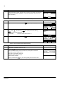
How to download a parameter set to a drive
You must have a template compat ble w th the dr ve where you ntend to download
the set. For check ng the dr ve nformat on, see How to view information about the
drive connected to the FlashDrop on page 27.
If there s no template w th the propert es you need, you have to download the
correct template from the Internet accord ng to the nstruct ons n How to download
templates from the Internet on page 28.
Step
1.
Action
Display
If you are not n the Ma n menu, press
EXIT
repeatedly unt l you get there.
NC
MAIN MENU
PARAMETERS
TIME & DATE
DRIVE INFO
OO:OO
1
SELECT
2.
Go to the Parameters mode by select ng PARAMETERS on the menu w th keys
SELECT
and
, and press ng
.
NC
SETS
1
1. Demo
2. Varying speed
3. 2 Cycles DI2
FlashDrop set O4
[ empty ]
EXIT
OO:OO SELECT
3.
Ensure that the dr ve s d sconnected from the ma ns (AC power source).
DRV
SETS
1
1. Demo
2. Varying speed
3. 2 Cycles DI2
FlashDrop set O4
[ empty ]
EXIT
OO:OO SELECT
Insert the programm ng t p n the FlashDrop connect on of the dr ve. Depend ng
on the dr ve type, the connect on s located on the front of the dr ve or n the
control panel recess.
The top left corner of the FlashDrop d splay shows now DRV nd cat ng that the
FlashDrop s connected to a dr ve.
4.
• Select the parameter set w th keys
and
, and press
to start
the download. Message "Download ng parameter set" s shown br efly.
or
• Select the parameter set w th keys
Then press
and
shown br efly.
and
, and press
SELECT
.
to start the download, or select DOWNLOAD w th keys
SELECT
and press
. Message "Download ng parameter set" s
DRV
SET ACTIONS
DOWNLOAD
INFO
EDIT
DELETE
EXIT
OO:OO
1
SELECT
The amount of parameter changes compared to default sett ngs affects the
download t me.
Operation
44
Step
5.
Action
Display
If the download succeeds, the panel LED s green for a moment and message
"Download successfully completed" s shown br efly before return ng to the
prev ous d splay.
DRV
MESSAGE
Download successfully
completed
OK
OO:OO
How to view information about the FlashDrop
Step
1.
Action
Display
If you are not n the Ma n menu, press
EXIT
repeatedly unt l you get there.
NC
MAIN MENU
PARAMETERS
TIME & DATE
DRIVE INFO
OO:OO
2.
Go to the FlashD Info mode by select ng FLASHD INFO on the menu w th keys
SELECT
and
, and press ng
. The d splay shows the follow ng
nformat on about the FlashDrop:
FIRMWARE:
3.
f rmware vers on of the base un t
Return to the Ma n menu by press ng
EXIT
.
1
SELECT
NC
FLASHD INFO
FIRMWARE
1O1A
EXIT
NC
OO:OO
MAIN MENU
TIME & DATE
DRIVE INFO
FLASHD INFO
OO:OO
1
SELECT
How to find out the control panel version
Step
Action
Display
1.
If the power s sw tched on, sw tch t off.
2.
Keep key ? pressed down wh le you sw tch on the power and read the
nformat on. The d splay shows the follow ng control panel nformat on:
Panel SW: panel f rmware vers on
Rom CRC: panel ROM check sum
Flash Rev: flash content vers on
Flash content comment.
When you release the
Operation
?
key, the control panel goes to the Ma n menu.
PANEL VERSION INFO
Panel SW:
x.xxx
Rom CRC:
xxxxxxxxxx
Flash Rev:
x.xx
xxxxxxxxxxxxxxxxxxxxx
45
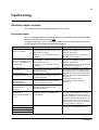
Fault tracing
What this chapter contains
The chapter l sts error messages and correct ve act ons.
Error messages
An error message shown on the panel d splay nd cates abnormal FlashDrop status.
Reset the FlashDrop by press ng OK .
Us ng the nformat on g ven n the table below, most error causes can be dent f ed
and corrected. If not, contact an ABB representat ve.
ERROR
CAUSE
WHAT TO DO
Download/Upload error 16
1) The programm ng t p s not nserted n
the FlashDrop connect on of the dr ve or
the connect on s loose.
1) Check that the programm ng t p s f rmly
nserted n the FlashDrop connect on of
the dr ve, see page 43.
2) The dr ve s not compat ble w th the
FlashDrop.
2) Check that the dr ve s compat ble w th
the FlashDrop, see page 13.
1) The programm ng t p s not nserted n
the FlashDrop connect on of the dr ve or
the connect on s loose.
1) Check that the programm ng t p s f rmly
nserted n the FlashDrop connect on of
the dr ve, see page 32.
2) The dr ve s not compat ble w th the
FlashDrop.
2) Check that the dr ve s compat ble w th
the FlashDrop, see page 13.
The dr ve type of the set s not the same
as the type of the dr ve where you are
download ng the set.
The dr ve rat ng of the set s not the same
as the rat ng of the dr ve where you are
download ng the set.
Download a compat ble set. If t does not
ex st, create a new set us ng the correct
template, see page 30. If the FlashDrop or
Dr vePM does not have the appropr ate
template, download t from the Internet,
see page 28.
The parameter table vers on of the set s
not the same as that of the dr ve where
you are download ng the set.
For check ng the set and dr ve
nformat on, see pages 34 and 27,
respect vely.
No dr ve connected
Upload error 51
Dr ve not connected or the
dr ve s not compat ble w th
the FlashDrop.
Download error 64
Incompat ble dr ve type
Download error 65
Incompat ble dr ve rat ng
Download error 68
Incompat ble dr ve
parameter table vers on
Download error 99
Incompat ble dr ve
local zat on
Set Open/Ed t/Download/
Upload error 35
No compat ble template
found
F le open fa led
F le save fa led
The local sat on of the set s not the same
as that of the dr ve where you are
download ng the set.
The set has been created us ng a
template that does not currently ex st n
the FlashDrop.
Download the m ss ng template from the
Dr vePM. If the Dr vePM does not have a
su table template, download t from the
Internet, see page 28. For f nd ng out the
propert es of the template used n the set,
check the dr ve type, area, control mode,
parameter table vers on and dr ve rat ng n
the set nformat on, see page 34.
F le system error
Try aga n. If the operat on st ll fa ls,
contact your local ABB representat ve.
F le clear fa led
CRC error
Fault tracing
46
Fault tracing
47
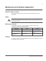
Maintenance and hardware diagnostics
What this chapter contains
The chapter conta ns prevent ve ma ntenance nstruct ons and LED nd cator
descr pt ons.
Safety
WARNING! Read the nstruct ons n sect on Safety instructions on page 13 before
perform ng any ma ntenance on the equ pment. Ignor ng the safety nstruct ons can
cause njury or death.
Maintenance intervals
The FlashDrop requ res very l ttle ma ntenance. The table l sts the rout ne
ma ntenance ntervals recommended by ABB.
Maintenance
Interval
Instruction
Base un t battery charg ng
Approx mately every four hours
See Charging on page 15.
Base un t battery replacement
As needed
See Battery replacement on
page 48.
Control panel battery
replacement
Every ten years
See Battery on page 48.
Software
It s poss ble to update the FlashDrop software us ng the Dr vePM program. See the
Dr vePM help for more nformat on.
Maintenance and hardware diagnostics
48
Base unit
Battery replacement
Replace the batter es when the FlashDrop needs frequent recharg ng.
1. Sw tch off the base un t and d sconnect the charger f n use.
2. Unscrew the screws n the bottom plate of the base un t and remove the plate.
3. T p the base un t sl ghtly to get out the battery holder.
4. Replace all the four batter es w th rechargeable 1.2 V AA N MH batter es. Use
only batter es stand ng 1.3 amperes charg ng current (spec f ed n the charger).
5. Put the battery holder back n place and attach the bottom plate.
6. Sw tch on the base un t.
3
2
4
3
4
4 rechargeable 1.2 V AA N MH batter es
Control panel
Cleaning
Use a soft damp cloth to clean the control panel. Avo d harsh cleaners wh ch could
scratch the d splay w ndow.
Battery
The control panel uses a battery to keep the real t me clock operat ng n memory
dur ng power nterrupt ons.
The expected l fe for the battery s greater than ten years. To remove the battery, use
a co n to rotate the battery holder on the back of the control panel. Replace the
battery w th type CR2032.
Note: The battery s NOT requ red for any control panel funct ons, except the clock.
Maintenance and hardware diagnostics
49
lEDs
The base un t nd cates the battery charge level w th four LEDs on the top r ght
corner (1 n the f gure). In add t on, the base un t has a green and a red LED on the
front (beh nd the control panel) to nd cate the status of the FlashDrop (2). The
control panel has one LED (3). The table below descr bes the LED nd cat ons.
Where
lED off
lED lit and steady
On the top r ght corner
of the base un t (1)
All LEDs off - no charge Green
left
lED blinking
Number of LEDs l t
nd cates the charge
level, dur ng charg ng all
LEDs are l t.
On the front of the base No power
un t (2).
If the control panel s
attached to the base
un t, remove t to be able
to see the LEDs.
Green
Ready
Green
-
Red
Operat on fa led. Press
OK to reset.
Red
-
At the top left corner of
the control panel (3)
Green
Set download, sav ng or Green
clear ng has succeeded.
-
Red
-
Operat on fa led. Press
OK to reset.
Ready
Red
1
3
2
Maintenance and hardware diagnostics
50
Maintenance and hardware diagnostics
51
Technical data
What this chapter contains
The chapter conta ns the techn cal spec f cat ons of the FlashDrop: we ght, t me of
use w th one charge, charge t me, amb ent cond t ons, mater als, appl cable
standards and mark ngs.
Weight
Approx mately 0.4 kg (0.88 lb).
Time of use with one charge
Approx mately four hours w th typ cal use.
Charge time
Approx mately 1.5 hours.
Ambient conditions
Temperature -10 to +40°C (14 to 104°F). No frost allowed.
Materials
Base unit and programming PC/ABS 1.5.2.0 mm and PA66+25%GF 1.0 mm, all n colour NCS 1502-Y (RAL 9002 /
tip enclosure
PMS 420 C)
Panel
PC/ABS 1.5.2.0 mm, colour NCS 1502-Y (RAL 9002 / PMS 420 C) and PC 1.2 mm,
clear
Package
Corrugated cardboard.
Disposal
The FlashDrop conta ns raw mater als that should be recycled to preserve energy and
natural resources. The package mater als are env ronmentally compat ble and recyclable.
All metal parts can be recycled. The plast c parts can e ther be recycled or burned under
controlled c rcumstances, accord ng to local regulat ons. Most recyclable parts are marked
w th recycl ng marks.
If recycl ng s not feas ble, all parts exclud ng electrolyt c capac tors and pr nted c rcu t
boards can be landf lled. The DC capac tors conta n electrolyte and the pr nted c rcu t
boards conta n lead, both of wh ch are class f ed as hazardous waste w th n the EU. They,
as well as batter es, must be removed and handled accord ng to local regulat ons.
For further nformat on on env ronmental aspects and more deta led recycl ng nstruct ons,
please contact your local ABB d str butor.
Applicable standards
• IEC/EN 61800-3 (2004)
The FlashDrop compl es w th the follow ng standard:
Adjustable speed electr cal power dr ve systems. Part 3: EMC requ rements and spec f c
test methods
CE marking
The FlashDrop carr es the CE mark ng.
Technical data
52
Dimensions
EMC VAR
Technical data
FlashDrop dimensions
The d mens onal draw ng of the FlashDrop s shown below. The d mens ons are
g ven n m ll metres and [ nches].
53
Glossary
Parameter table
The parameter table s the feature of dr ve's f rmware. The parameter table prov des
the parameters needed to def ne the user nterface to a dr ve. The dr ve's
parameters and the r ndexes, types, descr pt ve names, opt ons, value ranges and
select ons, default values, dependenc es on each other and act on flags are def ned
n the dr ve f rmware. All th s data together s called as parameter table.
Parameter table version
The parameter table has vers on number (P3305) wh ch has the same format as the
dr ve f rmware vers on (P3301). Whenever there s added new parameter n the
parameter table or there are made other changes n attr butes of the parameter
table, the parameter table vers on s changed. Typ cally the parameter table vers on
s changed when new dr ve f rmware vers on s released.
Parameter template
The dea of parameter template s the same as w th Power Po nt templates that are
turned nto presentat ons by add ng more nformat on to them. The template s the
descr pt on of dr ve's parameter table for offl ne data process ng purposes. For
nstance, the template makes t poss ble to ed t the values of parameters n offl ne
mode wh ch s always the case when operat ng w th FlashDrop base un t or Dr vePM
tool. The templates def ne all requ red parameter table attr butes (e.g. descr pt ve
names, value ranges and default values of parameters) n a form wh ch s supported
by both FlashDrop base un t and Dr vePM tool.
The templates are parameter table vers on spec f c b nary and ASCII f les. When
nstall ng the Dr vePM tool, the templates suppl ed by Dr vePM CD-ROM are
nstalled automat cally n ded cated Dr vePM subfolders. The template f le name
ncludes the parameter table vers on number. The templates supported by Dr vePM
tool have the f le extens on .par and the templates supported by FlashDrop base un t
have the f le extens on .fdt. For example, the template f le
251A_EUR_400V_Scalar_Industr al_En.par descr bes the parameter table of
European vers on of 400V ACS350 dr ve when used n scalar control mode n a form
that s supported by Dr vePM tool and the f le ACS350_251A_Eur_Scalar.fdt
descr bes the same content n a form that s supported by FlashDrop base un t.
To ensure that FlashDrop parameter sets are always 100% compat ble w th the dr ve f
rmware, t s requ red that the target dr ve and the parameter set have exactly the
same parameter table vers on. The parameter template s the base for the parameter
set. W thout template the creat ng and ed t ng of a parameter set s not poss ble.
Parameter set
The parameter set stores the parameter values and v s b l ty nformat on together
w th header and template related nformat on (e.g. set's name, author, creat on date
and t me, dr ve type and rat ng, local zat on and control mode). Based on the use of
selected template the FlashDrop parameter set s created w th FlashDrop base un t
or w th Dr vePM PC tool (and then downloaded to the base un t). The parameter set
Glossary
54
can be downloaded from the FlashDrop base un t to a dr ve. Dur ng the next power
up of a dr ve, the downloaded parameter set comes over to act ve parameter set,
custom zes dr ve's control panel v ew and updates the content of user sets and
overr de set.
Size dependent / Size independent
The dr ve s ze dependent parameter set s compat ble only w th dr ves wh ch s ze
(rat ng) compl es w th the s ze of the set n quest on. The dr ve s ze ndependent
parameter set can be downloaded n a dr ve w thout rat ng l m tat on.
Glossary
55
Additional information
State diagram of the panel user interface
Start
Main menu
Enter
Parameters
Exit
01: OEM A
Download
View
Parameter set
info screen
Download
Exit
Drive info
screen
Exit
Sel
Sel
02: OEM B
View
Drive info
Parameter set
actions
Parameter set
selection
Exit
Info Edit
Sel
03: FD 03
Open set
View
FlashDrop info
FlashDrop
info screen
Exit
Delete
Exit
04: John 3
Time & date
05: [ empty ]
Sel
Exit
Enter
Cancel
Cancel
Clock menu
Init
Clear
Confirm delete
dialog
Set time
Create type
selection
Set date
Upload
Clock visibility
Time format
Date format
Daylight saving
New set
Attribute selection
Attribute selection
Drive rating
selection
Template
selection
Default visibility
selection
Drive rating
selection
Default visibility
selection
Saving...
Cont nues to the next page.
Additional information
56
Parameter groups
01 Operating data
Parameter list
0102 Speed
Sel
03 ...
0103 ...
Exit
04 ...
0104 ...
Yes
No
Save
Cancel
Parameter
edit
0105 ...
10 ...
Show hidden?
Edit
99 ...
Parameter value
is shown
Exit
Sel
Changed Par list
Edit menu
Edit values
Active set
Exit
User set1
Sel
Exit
Exit
Cancel
Override set
No
Saving...
Edit parameter
visibility
Confirm
changes
Yes
Edit group
visibility
Exit Sel
Sel
Parameter groups
Show/
Hide
03 ...
02 ...
04 ...
03 ...
10 ...
04 ...
99 ...
Visibility setting of the
selected item is shown.
Toggle setting with
soft key 2.
Cont nued from the prev ous page.
Parameter visibility
list
01 Operating data
01 Operating data
Additional information
Save
Cancel
9905 ...
Changed
parameters
User set3
Group visibility list
Edit
1004 ...
5101 ...
Sel
User set2
Exit
1003 Direction
Sel
Exit
0102 Speed
0103 ...
0104 ...
0105 ...
Current setting
is shown
Show/Hide
Parameter
edit
57
Drive ratings table
200V,
1phase
200V,
3phase
400V,
3phase
ACS1S0
ACS3S0
short size code
ACS150-01x-02A4-2
ACS350-01x-02A4-2
2A41
ACS150-01x-04A7-2
ACS350-01x-04A7-2
4A71
ACS150-01x-06A7-2
ACS350-01x-06A7-2
6A71
ACS150-01x-07A5-2
ACS350-01x-07A5-2
7A51
ACS150-01x-09A8-2
ACS350-01x-09A8-2
9A81
ACS150-03x-02A4-2
ACS350-03x-02A4-2
2A42
ACS150-03x-03A5-2
ACS350-03x-03A5-2
3A52
ACS150-03x-04A7-2
ACS350-03x-04A7-2
4A72
ACS150-03x-06A7-2
ACS350-03x-06A7-2
6A72
ACS150-03x-07A5-2
ACS350-03x-07A5-2
7A52
ACS150-03x-09A8-2
ACS350-03x-09A8-2
9A82
ACS350-03x-13A3-2
0132
ACS350-03x-17A6-2
0172
ACS150-03x-01A2-4
ACS350-03x-01A2-4
1A24
ACS150-03x-01A9-4
ACS350-03x-01A9-4
1A94
ACS150-03x-02A4-4
ACS350-03x-02A4-4
2A44
ACS150-03x-03A3-4
ACS350-03x-03A3-4
3A34
ACS150-03x-04A1-4
ACS350-03x-04A1-4
4A14
ACS150-03x-05A6-4
ACS350-03x-05A6-4
5A64
ACS150-03x-07A3-4
ACS350-03x-07A3-4
7A34
ACS150-03x-08A8-4
ACS350-03x-08A8-4
8A84
ACS350-03x-12A5-4
0124
ACS350-03x-15A6-4
0154
ACS350-03x-23A1-4
0234
Additional information
58
200V,
3phase
ACS&ACHSS0
short size code
ACx550-xx-04A6-2
4A62
ACx550-xx-06A6-2
6A62
ACx550-xx-07A5-2
7A52
ACx550-xx-012A-2
0122
ACx550-xx-017A-2
0172
ACx550-xx-024A-2
0242
ACx550-xx-031A-2
0312
ACx550-xx-046A-2
0462
ACx550-xx-059A-2
0592
ACx550-xx-075A-2
0752
ACx550-xx-088A-2
0882
ACx550-xx-114A-2
1142
ACx550-xx-143A-2
1432
ACx550-xx-178A-2
1782
ACx550-xx-221A-2
2212
ACx550-xx-248A-2
2482
Additional information
59
400V,
3phase
400V,
3phase
ACS&ACHSS0
short size code
ACH550-01-02A4-4
2A44
ACx550-xx-03A3-4
3A34
ACx550-xx-04A1-4
4A14
ACx550-xx-05A4-4
5A44
ACx550-xx-06A9-4
6A94
ACx550-xx-08A8-4
8A84
ACx550-xx-012A-4
0124
ACx550-xx-015A-4
0154
ACx550-xx-023A-4
0234
ACx550-xx-031A-4
0314
ACx550-xx-038A-4
0384
ACx550-xx-044A-4
0444
ACx550-xx-045A-4
0454
ACx550-xx-059A-4
0594
ACx550-xx-072A-4
0724
ACx550-xx-077A-4
0774
ACx550-xx-078A-4
0784
ACx550-xx-087A-4
0874
ACx550-xx-096A-4
0964
ACx550-xx-097A-4
0974
ACx550-xx-124A-4
1244
ACx550-xx-125A-4
1254
ACx550-xx-157A-4
1574
ACx550-xx-180A-4
1804
ACx550-xx-195A-4
1954
ACx550-xx-246A-4
2464
ACx550-xx-02A7-6
2A76
ACx550-xx-03A9-6
3A96
ACx550-xx-06A1-6
6A16
ACx550-xx-09A0-6
9A06
ACx550-xx-011A-6
0116
ACx550-xx-017A-6
0176
ACx550-xx-022A-6
0226
ACx550-xx-027A-6
0276
ACx550-xx-032A-6
0326
ACx550-xx-041A-6
0416
ACx550-xx-052A-6
0526
ACx550-xx-062A-6
0626
ACx550-xx-077A-6
0776
ACx550-xx-099A-6
0996
ACx550-xx-125A-6
1256
ACx550-xx-144A-6
1446
Additional information
60
Additional information
บริษัท ที.จี. คอนโทรล จำกัด
ABB limited
Daresbury Park
Daresbury
Warr ngton
Chesh re
WA4 4BT
UNITED KINGDOM
Telephone
+44 1925 741111
Fax
+44 1925 741212
ABB Oy AC
Dr ves P.O.
Box 184
FI-00381 HELSINKI
FINLAND
Telephone
+358 10 22 11
Fax
+358 10 22 22681
Internet
www.abb.com
ABB Inc.
Automat on Technolog es
Dr ves & Motors
16250 West Glendale Dr ve
New Berl n, WI 53151
USA
Telephone
262 785-3200
800-HELP-365
Fax
262 780-5135
ABB Beijing Drive Systems Co. ltd.
No. 1, Block D, A-10 J ux anq ao Be lu
Chaoyang D str ct
Be j ng, P.R. Ch na, 100015
Telephone
+86 10 5821 7788
Fax
+86 10 5821 7618
Internet
www.abb.com
3AFE68591074 Rev B / EN
EFFECTIVE: 5.3.2007
1683 ทาวน์อินทาวน์ ซอย 9 แขวงพลับพลา เขตวังทองหลาง กรุงเทพฯ 10310
โทร. 02-530-9090 แฟกซ์. 02-530-9933 www.tgcontrol.com, www.facebook.com/tgcontrol