1
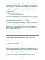
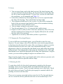
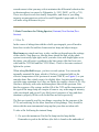
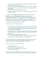
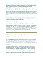
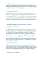
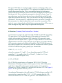
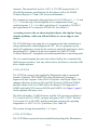
A Taste of ESPRESSO
or
How to Use The San Pedro Martir
REOSC Echelle Spectrograph
S. Levine
Observatorio Astronómico Nacional
IA-UNAM, Ensenada, B.C., Mex.
[email protected]
and
D. Chakrabarty
California Institute of Technology
Pasadena, CA, USA
IA-UNAM
TECHNICAL REPORT # MU-94-04
submitted 24 August 1994
1.0a - revised 4 October 1994
1.0b - revised 20 April 1995
version 1.0b
Contents:
1. Spectrograph Characteristics
1.1 General Information
1.2 The Cameras
1.3 Efficiency and Response
2. How to Adjust the Spectrograph for Your Needs
2.1 Focusing the Spectrograph
2.2 Changing the Wavelength Region
2.3 Rotating the Slit
3. Basic Procedures for Taking Spectra
1 of 22
3.1 How To
3.2 Taking Standard Star Spectra
4. The UCL Camera
4.1 UCL Camera Specifications
4.2 Positioning the Spectrum
5. The REOSC Camera
5.1 REOSC Camera Specifications
5.2 Positioning the Spectrum
5.3 Moving the Focal Plane Stage
6. Detectors
6.1 The CCD-Mil
6.2 The CCD-Tek
6.3 The CCD-UMass
7. General Caveats
8. Appendix - Some Basic Optics
9. References and Other Useful Documents
10. Pictures of the Spectrum
List of Tables
List of Figures
1. Spectrograph Characteristics (Contents| Next Section)
The Echelle Spectrograph at San Pedro Martir (SPM) was constructed in the
late 1970's by the French Optical firm of REOSC. The echelle is capable of a
resolution of R ~ 18,000 at 5,000Å, with either of its two camera/detector
setups. This translates into a 2 pixel velocity resolution of roughly 17 km/s
A note on the choice of name. The echelle (unlike the newer instruments at
San Pedro) has not been graced with a name other than to call it ``the echelle''
(at least as far as the author is aware). While writing this manual, I had a free
moment to ponder this terrible state of affairs, and propose to call the echelle
ESPRESSO (for ESPectrografo Reosc Echelle de Sierra San pedro martir,
Observatorio or if you prefer, Echelle SPectrograph from REosc for the Sierra
San pedro martir Observatory). Thus, this is the ESPRESSO User's Guide, and
if you like, you can tell your friends that you are up on the mountain using the
ESPRESSO Machine.
1.1 General Information
The layout of the main optical elements of the spectrograph is shown in Figure
2 of 22
1, and the instrument controls in Figure 2. The main echelle grating is ruled
on a 254mm×128mm area, and has 79 lines/mm. The blaze angle is 63°433,
and the incidence angle is 71°. The beam is dispersed into an angle of ±2°63.
The dispersion depends upon the order, and ranges from 4Å/mm to 16Å/mm.
The values differ slightly depending upon which of the two available cameras
you are using (see the sections on the two cameras - ucl or reosc).
The two grating cross-dispersers available are listed in Table 1 . The 900
lines/mm cross-disperser (B) was most useful when the detector was a
photographic plate. With a CCD (and its much smaller detector surface area),
the 300 lines/mm grating (A) is more useful. With this, it is possible to fit
between 8 (near Halpha) and 16 (near 4,000Å) orders onto the chip with the
REOSC/UMass setup, or between 12 and 30 orders onto the UCL/Mil setup.
The current default setup uses cross-disperser A, with the UCL camera and the
CCD-Mil detector.
There are half a dozen comparison lamps available (see Table 2). The lamp
housing has three permanently mounted lamps, and one hole that permits the
easy interchange of additional lamps. Currently mounted in the permanent
sockets are lamps of Argon, Cesium and Rubidium. In the open hole, a
Thorium-Argon lamp (with its own voltage supply) can be mounted. The flat
lamp mounting socket also fits in the same hole, and Neon and Helium-Argon
bulbs can be fitted into this socket. On the underside of the lamp housing, a
sliding diffuser is mounted. To insert the diffuser, push up (in). It should click
into position. This is used with the flat lamp to help ensure even illumination
of the slit. The most commonly used comparison lamps currently are the
Th-Ar and the He-Ar.
Each of the permanently mounted lamps has a switch on the lamp housing.
There is a mirror in the housing that can be rotated to select which lamp is
reflected onto the slit assembly. The mirror can be pulled out (and should be)
when using light sources that mount in the open socket (the flat lamp, the
Th-Ar, He-Ar, etc.). To remove the mirror from the light path, pull outward on
the knob which rotates the mirror.
The spectrograph has a continuously adjustable slit , with a minimum slit
width of 30µm, and a maximum of 900µm. Presuming that you are using the
f/7.5 secondary, the plate scale 1.33×10¯²''/µm. The optimum slit width
(matched to 2 pixel resolution) is close to 2 arcseconds (150µm) (see Table 11
in the appendix). We present some typical slit sizes in microns and arcseconds
in Table 3.
3 of 22
The slit viewer observes an 18 mm diameter field around the slit. An
intensified CCD camera that can be used to view the slit is currently being
tested out. This replaces the eyepiece, and should allow the observer to both
acquire objects and guide on the slit (the ability to guide on the slit is
dependent upon the slit size used). As it exists now, the camera has no
difficulty reaching tenth magnitude objects (as faint as I have seen tried) and
should be able to image at least as faint as twelfth magnitude for useful
guiding.
The slit length is 30 mm (6'.7) but it can be shortened using a series of masks
or deckers. The masks typically come in pairs, and there are 10 masks all
together. Each pair consists of a central mask, and a double mask positioned
outside the central mask. This permits the observer to make two
non-overlapping exposures on the same image (subject to the inter-order
spacing). The widths of the masks are given Table 4. Pulling the mask slide all
the way out (beyond mask position 10) permits the user to view the whole slit
length (or at least the full field of view of the slit viewer eyepiece). Which
mask you use is dependent upon the wavelength region you wish to observe.
The further towards the blue you wish to observe, the more closely spaced the
orders become, thus limiting the length of the slit that you can effectively use
without getting overlap of the orders. The cross disperser and camera optics
magnify the image of the length of the slit (see the appendix), just as the
echelle grating and camera optics magnify the slit width (hence the derived
optimum slit width). In Figure 3, the distance between the order centers is
plotted, and overlaid upon that are dashed lines showing the length of the slit
as it actually appears on the detector. For the orders NOT to overlap, the
inter-order spacing must be greated than the image length. So, with the 2 mm
mask (#7), all the orders redward of order 50 (lambda > 4400Å) should not
overlap. Of course, you will want to leave some space between the orders, so
effectively, this means that you should not go all the way to order 50. At
4200Å the maximum slit length for no overlap is 1 mm = 13''.3 (decker
number 8, see the Figure accompanying Table 4 and also Figure 3 ).
1.2 The Cameras
There are now two cameras available for use with the echelle. The first has
been recently constructed at University College London, and is paired with a
1024×1024 CCD detector (either the CCD-Mil or the CCD-Tek). We shall
refer to this system as the UCL camera. This is the current default
configuration for the echelle.
The second camera is the original REOSC camera, which is used with a
4 of 22
512×512 CCD run by a system put together by Photometrics (CCD-UMass).
We shall call this combined camera and CCD setup the REOSC camera.
1.3 Efficiency and Response
Be aware that there is a very wide range in response with wavelength of the
system as a whole (including the CCD), and it is likely that some regions of
your spectra will be saturated while others are barely exposed. The blaze
functions for the first order of the cross dispersers are shown in the top panel
of Figure 4, along with the typical blaze function along each of the echelle
orders (bottom panel).
To help point out somewhat more the wide dynamic range of the system as a
whole, Figure 5 shows first the (panel 1), and the the product of the QE and
the cross disperser A blaze function (panel 2). To illustrate how these might
combine with some typical input spectra, panel 3 shows black body spectra for
objects of temperatures 3200°K (an approximation of a tungsten flat lamp)
and 5800°K (roughly solar), and panel 4 shows what the relative output
intensities would be. Note that the total relative intensities are better than you
will actually get, since we have not included transmission and reflection loss
from all of the rest of the various optical elements.
How long do you need to integrate to reach a given Signal to Noise ratio (S/N)
for a given magnitude?
S/N(lambda) = sqrt[e¯/(pixel in echelle dispersion direction)]
= sqrt{[gamma = # photons above the atmosphere/(s cm² Å)]
× [epsilon = % transmission of atmosphere, telescope, & echelle]
× [A = collecting area = pi r² (cm²)]
× [Delta x = Å / pixel]
× [QE = e¯ / photon]
× [t = integration time in seconds] }
We can re-write gamma in terms of V magnitudes (lambda = 5556Å) as
gamma(V) = 948 × 10^{-V/2.5} photons/(cm² s Å) ,
where the 948 is the number of photons from a star of magnitude
V=0.(Actually, this is the monochromatic flux at 5556Å, but for a rough
estimate it will be close enough. See Mihalas & Binney, 1981,Galactic
Astronomy, p. 62.) So,
S/N(lambda) = sqrt{ 948 × 10^(-V/2.5)
× epsilon A (Delta x)(QE) t }.
5 of 22
For the 2 meter telescope at SPM, at 5,000Å, A=31416cm². With the UCL
camera and CCD-Mil chip, (Delta_x) = 0.14Å/pixel. We'll assume that the
CCD QE is about 15%, and that the combined transmission epsilon~6% (this
presumes 90% transmission or reflectance at every optical element and
through the atmosphere, and 40% at each of the gratings). When combined
with the QE of the CCD this gives a throughput of just under 1%. So, the
S/N(lambda) will be
S/N(lambda) ~ sqrt{ 39,000 × 10^(-V/2.5) t
× e¯/(pixel in echelle dispersion direction)}.
This is the S/N you should get after you sum together the pixels dispersed in
the spatial direction. For those who cannot do this, divide this number by the
number of pixels in the cross-disperser direction (let us estimate it at 4 for ease
of illustration) making the S/N(pixel)=1/2×S/N(lambda).
The example above is probably a bit optimistic. Remember too that the S/N is
also going to depend upon the wavelength, and the spectral structure of the
object under study. You are advised to take several spectra of various
magnitude objects to get an empirical value for the constant term in the S/N
relations, which are summarized below: (a) S/N given V and t, (b) t given S/N
and V, (c) V limit given t and S/N.
(a) S/N = sqrt { const × 10^(-V/2.5) t }
(b) t = (S/N)² × 10^(V/2.5) / const
(c) V = -2.5 log10 [(S/N)² /(const × t)]
2. How to Adjust the Spectrograph for Your Needs (Contents| Next
Section| Prev. Section)
First, don't forget to focus the telescope.
2.1 Focusing the Spectrograph
In addition to focusing the telescope, it is also necessary to make sure that the
spectrograph is focused. The spectrograph is focused by moving the
collimator using the micrometer on the bottom of the instrument housing. The
telescope should be pointing at or near the zenith for focusing. This procedure
can be done fairly rapidly with two people, and should be done everytime the
dewar is removed and replaced. We found that once done in the early evening,
the focus would remain ok for the rest of the night. The smallest line widths
(FWHM) you will realistically be able to achieve are about 2.5 pixels.
6 of 22
To focus:
1. Turn on an arc lamp, push in the knob on top of the lamp housing, and
set up a small slit (say about 40µm - the key point here is really only that
the slit be small enough that the CCD pixel size, not the slit width limits
the resolution - see the appendix and Table 11).
2. Unlock the collimator by loosening the three set screws spaced around
the side of the housing. These should only be finger tight.
3. The collimator should now be free to move. It is moved by turning the
knob of the micrometer found on the bottom of the instrument housing.
This micrometer can be difficult to turn.
4. Take an image, noting the micrometer setting.
5. Turn the micrometer 0.5 or 1.0 turns and take another image.
6. Repeat (4) and (5) until you have acheived a satisfactory focus. Be aware
that the optimum focus settings may be slightly different for the red and
the blue ends of the spectrum.
7. Tighten the set screws by hand when you have a good focus.
2.2 Changing the Wavelength Region
To access different wavelength regions, you will need to rotate the cross
disperser. On your images, you will see that this causes motion perpendicular
to the dispersion direction of the orders. The cross disperser angle is set with a
circular micrometer on the lower side of the instrument housing. Course
adjustment is done by loosening the right thumb screw and turning the grating
holder by hand. Fine adjustment is done using the left thumb screw. The right
hand thumb screw should be tightened before doing fine adjustment. Using the
vernier, you can read the grating tilt angle to one minute of arc.
Maps of grating angles, blaze wavelengths and visible orders are given in each
of the sections on the two possible camera setups.
2.3 Rotating the Slit
To rotate the echelle slit, the whole instrument is rotated on the telescope
mounting. There are two locking knobs and a third knob that causes the
mounting platen to rotate. There is an angle indicator next to this knob. Check
the value when you begin. Usually the spectrograph is mounted with the slit
pointing in an east-west direction.
There are two reasons you might wish to rotate the slit. The first and obvious
one is to orient the slit in a particular direction on an extended object. The
7 of 22
second reason is that you may wish to minimize the differential refraction due
to the atmosphere (see paper by Filippenko, A. 1982, PASP, vol. 94, p.715).
These two objectives are not usually compatible, and those of you doing
intensity measurements are advised to read Filippenko's paper and see if this
will make a big difference for you.
3. Basic Procedures for Taking Spectra (Contents| Next Section| Prev.
Section)
3.1 How To
In the course of taking data with the echelle spectrograph, you will need to
know how to take flat and bias frames and arc lamp and object images.
Bias frames are simple and easy to take, and do not depend upon the settings
of the echelle. Note however, that the dome should be dark, as the whole
system is not totally light tight, and if you take a bias with bright lights on in
the dome, you will notice a gradient in the bias images (this has been seen
with both the CCD-Mil and the CCD-UMass). There is also some scattered
light in the system.
When taking flat field images, you have several options. You can use the
internally mounted flat lamp, which is (I believe) a tungsten bulb (so the
effective temperature of the spectrum is around 3200°K, see Figure 5) or you
can take dome flats, which seem to be slightly bluer, but take much longer to
reach the same saturation level (they are fainter by roughly a factor of 10). Sky
flats have difficulty with solar and atmospheric lines in the spectrum. Note
that the response of the system, and the QE of the CCD and the temperature of
the typical flat image lamp all conspire to cause a very wide range in intensity
with wavelength, and you will very likely need exposures of long and short
duration to properly fill the wells in the blue and red respectively.
The flats are typically used for two things, correcting for the response of the
CCD, and correcting for the blaze functions of the gratings. They should be
taken with the same instrumental setup up that your data are taken with.
To take a flat field using the internal lamp:
1. Go up to the instrument. Put the flat lamp into the lamp holder.
Remember to push in the diffuser (the slide is found on the underside of
8 of 22
the lamp housing), and pull out the rotating mirror. The diffuser helps to
ensure even illumination of the slit.
2. Push the knob on top of the lamp housing IN. This reflects the lamp light
down through the spectrograph slit, and blocks out the optical path from
the telescope.
3. Set the desired slit width, and choice of mask.
4. Take an n second exposure, where n is long enough to mostly fill, but not
saturate the image.
For images of the comparison lamps , you are presented with a plethora of
possibilities, but the most commonly used lamps currently are the
Thorium-Argon lamp and the Helium-Argon lamp. (G. Koenigsberger, G.
Canalizo and D. Peña have recently compiled a Th-Ar atlas using this echelle.
In addition, there are two high resolution line atlases are available for the
Th-Ar lamp, one from the AAT and one from KPNO, and J. Echevarria has
compiled a He-Ar lamp atlas using this echelle.)
To take a spectrum of a comparison lamp:
1. Choose the comparison lamp you wish to use, and turn it on. Remember
to rotate the mirror to the proper setting, or to pull it out if you are using
one of the bulbs that mounts in the same holder as the flat lamp, and if
necessary to push in the diffuser.
2. Push the knob on top of the lamp housing IN. This reflects the lamp light
down through the spectrograph slit, and blocks out the optical path from
the telescope.
3. Set the desired slit width, and choice of mask.
4. Take an n second exposure. Typically for the Thorium-Argon lamp, a 60
second exposure is long enough to give well defined lines.
Now, go find your objects! For fainter objects, you may well find it necessary
to take several shorter exposures and co-add the images later, since the
number of cosmic rays in a 15 minute exposure is fairly high.
To take a spectrum of an astronomical object:
1.
2.
3.
4.
Turn off all the lamps.
Pull the knob on the lamp housing OUT.
Set the desired slit width, and choice of mask.
Take an n second exposure.
Depending upon the wavelength region you are working in, you may need to
insert a long pass filter to block out overlap from the second and third orders
9 of 22
of the cross-disperser. We use the first order of the cross-disperser to separate
the echelle orders. Second and third order images also show up on the image
plane. For stellar spectra, this is not a problem shortward of about
6,500-7,000Å, since the atmosphere effectively blocks transmission of much
of the radiation short of 3,000Å. However, if you wish to observe further
towards the red, you will want to have a long pass filter to remove the second
and third order spectra. For the comparison arcs, technically this is a problem
for all the echelle orders, since you don't have the atmosphere to cut out the
violet, though the first order is substantially brighter than the second and third
orders.
While we do not currently have an optical quality long pass filter, some tests
have already been made with a photographic wratten filter placed in a
temporary mounting behind the slit assembly.
3.2 Taking Standard Star Spectra
For absolute flux calibration, you will need standard star spectra. The
spectrophotometric standards given by P. Massey, K. Strobel, J. Barnes and E.
Anderson (1988, ApJ, 328, 315) are available on line in IRAF, along with
several other sets of spectrophotometric standards. When in IRAF, type ``page
onedstds$README'' to see a listing of the standards. Copies of the finder charts
for the Massey et. al. standards should be in the control room.
4. The UCL Camera (Contents| Next Section| Prev. Section)
4.1 UCL Camera Specifications
The UCL camera was recently constructed at University College London to
replace the original REOSC camera. First observations with the new camera
were done in the fall of 1993. The camera has a focal length of 215.6 mm.
This camera is used with the CCD-Mil (see section 6.1) and the CCD-Tek (see
section 6.2).
This camera setup is capable of observing between 3,000Å and 11,000Å,
though not all at once. For orders 74 through 34 (the blue end from about
3,000Å to about 6,700Å, including Halpha in order 34, Hbeta; in order 46,
Hgamma in order 52, and Hdelta) the CCD can be set to cover the complete
free spectral range. For wavelengths longer than about 6,700Å (orders 33
through 20), the percentage of coverage steadily decrease until in order 20,
10 of 22
only about 5/8 of the free spectral range is on the chip. According to J.
Echevarria, it is possible to cover the entire range from 3,000Å to 11,000Å in
three or four overlapping frames: Orders 74 through 41, 40 through 27 and 26
through 20. To observe redder than Halpha, it is necessary to insert a filter to
cut out the overlap from the second and third orders.
4.2 Positioning the Spectrum
To determine what portion of the spectrum is imaged onto the CCD, you can
rotate the cross-disperser using the rotating micrometer on the side of the
echelle housing. See Table 5 for a list of which wavelength regions are imaged
onto the CCD at which micrometer angles. Figure 6 illustrates where the
orders lie on the camera focal plane, and the box shows the size of the CCD.
Note that you get the full free spectral range for all orders bluer than order 34.
5. The REOSC Camera (Contents| Next Section| Prev. Section)
5.1 REOSC Camera Specifications
The REOSC camera has a focal length of 204 mm, and is constructed of a
spherical plate mirror with a double lens afocal correcting plate and a field
lens. It has a flat field of 8° × 5°2 with an f/1.4 focal ratio. The blur circle is
less than 15µm\ for every wavelength in the whole field. The central
wavelengths of the orders are given in Table 8. Because of the short focal
length of the camera, it is necessary to guide the light from the focal plane to
the CCD using a fiber optic bundle. The only CCD equipped with the
necessary fiber bundle is the CCD-UMass (see section 6.3). The CCD is not
quite large enough to encompass the whole free spectral range of most of the
orders, so provision is made for moving the CCD mounting stage. Details of
how to do this are given below.
5.2 Positioning the Spectrum
To determine what portion of the spectrum is imaged onto the CCD, you can
rotate the cross-disperser using the rotating micrometer on the side of the
echelle housing. See Table 7 for a list of which wavelength regions are imaged
onto the CCD at which micrometer angles. Figure 7 illustrates where the
orders lie on the camera focal plane, and the box shows the size of the CCD.
5.3 Moving the Focal Plane Stage
11 of 22
Because CCD-UMass is not big enough to capture overlapping orders, it is
possible to move the stage that the CCD is mounted on roughly parallel to the
echelle dispersion direction. This is accomplished using the micrometer
mounted on the left hand side of the dewar (when facing the instrument from
the dewar side). Move so that the micrometer is directly in front of you. To
move the stage, you first loosen the two brass colored bolts on the left and
right sides just below the stage. Now, you can move the stage by turning the
micrometer. This micrometer is calibrated in inches, not meters. Attached to
the micrometer is a digital readout that can be zeroed at any position. This
makes it easy to change back and forth between stage positions. When you are
done moving the stage, don't forget to tighten the locking nuts.
6. Detectors (Contents| Next Section| Prev. Section)
A note before we begin: the gain factor and CGAIN are NOT the same thing.
The gain factor (f) is just that, the ratio of the number of electrons/ADU
relative to the number of electrons/ADU when the A/D converter's range
equals the full well depth. Hence, a gain of 1 implies that the A/D converter
should saturate when the CCD's wells fill. A gain factor of 2 implies that the
A/D converter saturates at half the well depth etc. The CGAIN that many of
the control programs use is a holdover from the Photometrics control systems.
CGAIN is related to the gain, typically by a formula like
CGAIN = C_1 × (f - 1) + C_2
where the constants C_1 and C_2 vary depending upon the CCD and
controller. C_1 is usually either 15 or 30 and C_2 either 0 or 11 (see
IA-UNAM Technical Report #102).
6.1 The CCD-Mil
The CCD-Mil system features a Thompson THX31156 CCD with a
Metachrome II coating to improve blue response. It has 1024×1024 pixels,
each 19µm×19µm. This chip is most sensitive in the red; its quantum
efficiency at 7,000Å is about 40%, and at 4,000Å is about 15%. See Figure 5,
panel 1 for the quantum efficiency curve.
According to Photometrics, the well depth is 173,000 electrons, and the A/D
converter has a range from 0 to 2^14-1 = 16,383, meaning that the A/D
conversion factor is 10.6 e¯/ADU at a gain of 1. The readout noise is 5.71
12 of 22
electrons. The normal bias level at -110°C is 275 ADU at gain factor of 1.
(See the Photometrics specifications for this chip as well as IA-UNAM
Technical Reports # 97 and # 102 for more information.)
The constants for conversion from gain factor (f) to CGAIN are C_1 = 15 and
C_2 = 11 for this chip. Note though that as it is implemented in the elmil
control program, C_2 = 0, so that a gain factor of 1 is entered as CGAIN=0
and a gain factor of 5 is entered as CGAIN=60. (See Table 9.)
A warning to users who are observing faint objects, this chip has charge
transfer problems, which you will most likely see on one edge of your
orders.
The CCD-Mil chip is run using the elmil program on the Sun workstations or
using a photometrics control program on a PC. The elmil program is pretty
much self-explanatory (except for the section on setting the gain factor), and is
documented by L. Gutierrez in the user's manual (see also IA-UNAM
Technical Report #97, though the system documented there is not being used).
The elmil control program does not seem to have facility for a continual chip
flush between exposures. You may wish to take a few biases to clear the wells
after a bright exposure.
6.2 The CCD-Tek
The CCD-Tek system is also supplied by Photometrics and is constructed
around a Tektronix TK1024AB CCD with a Metachrome II coating to
improve the blue response. It has 1024×1024 pixels, each 24µm×24µm. The
quantum efficiency is between 30% and 40% between 2,500Å and 5,000Å,
and then climbs to 65% at 6,000Å before declining to 50% longward of
8,000Å and finally 30% between 9,000Å and 10,000Å. See Figure 5, panel 1
for the quantum efficiency curve.
The full well depth is 319,000 electrons, and the A/D converter resolution is
2^16, from 0 to 65,535 ADU's, giving a unit gain of 4.88 e¯/ADU. The bias
level at gain of 1 is 944 ADU, and the tested dark current at the operating
temperature of -100°C is 0.76 e¯/pixel/hour. (See Table 10.)
This system is being documented by J. A. Lopez.
6.3 The CCD-UMass
The CCD-UMass system has been assembled and packaged by Photometrics,
13 of 22
and the whole package is referred to as a Photometrics 3000 system. The
detector in the CCD-UMass camera is a Ford Aerospace PM 512 CCD (this
division of Ford Aerospace has since been sold to the Loral Corporation). It
actually has 516×516 pixels, each 20µm×20µm, though the user can only use
512×512. The CCD wells are 250,000 electrons deep, and the A/D converter
has a dynamic range from 0 to 2^14-1 = 16,383 ADU's. Readout noise is
between 7 and 12 electrons/pixel rms, and the unit gain (with CGAIN=0) is 15
e¯/ADU (IA-UNAM Technical Report #102).
A fiber optic bundle is cemented to the face of the chip. This bundle is made
up of 5µm fibers in roughly hexagonal sheaves. The operating temperature
range is -90°C to -130°C, with typical temperatures being -101°C and -110°C.
If the dewar is filled at the beginning of the night, the charge will normally
last all night. Once the temperature of the CCD system stabilizes, the
temperature probably won't vary by more than than 0.1°C over the course of
the night.
The gain conversion factors for this CCD are C_1 = 30 and C_2 = 0.
6.3.1 Basic Operation
The computer control for the CCD-UMass system is a Heurikon Systems
computer running a system V version of the Unix operating system. The CCD
control software is called ccd_oan, and is a FORTH interpreter written in C.
Usually you will find the Heurikon up and running, but just in case, we now
tell you how to (re-)boot the computer (see IA-UNAM Technical Report #61
for more details).
1. Turn on the power to the computer. The switch is on the front of the box
that says Photometrics 3000. Turn on the HDS terminal (this is the
computer console).
2. When the ``>'' prompt appears, type ``bw <return>''. This begins the
boot-strap process.
3. After several messages, the computer will say ``Standalone boot''. At the
``:'' prompt, type ``<return>''.
4. Several more messages will scroll by, and then the computer will prompt
you with ``type return to start at 0x100''. You type ``<return>''.
5. Finally, the basic unix system will be up and running in single user
mode, and the system will say ``Welcome to UNIX System (7a)'' and
display a ``#'' prompt. At this point, you should type ``init 2''. This will
tell the system to initialize multi-user mode.
6. The computer will next ask if you wish it to check the file system. You
should answer ``y<return>'', unless you know for sure that the file system
14 of 22
is ok and uncorrupted. The checking should take no more than 3 to 5
minutes.
7. Presuming all has gone well, the next prompt you receive will be a
standard UNIX login prompt, ``login:''. Log on as ``ccd'' (no password).
Congrats, the computer is now up, and ready to run the CCD control
program.
8. Type ``ccd_oan'' to start up the FORTH interpreter that controls the
CCD.
Since you know how to start the computer, you should also know how to shut
it off (in case the power goes out for example). Shut down is a much simpler
procedure.
1. If you are in ``ccd_oan'', type ``quit'' to exit.
2. At the UNIX prompt ``%'' type ``su <return>''. This will log you in as the
root user. You will now have the access necessary to shut down the
computer gracefully.
3. At the UNIX prompt ``#'', type ``sync <return>''. Now, type it again.
4. You should now turn off the power on the computer box labeled
Photometrics 3000, then the power to the HDS terminal and the Cabel
graphics terminal, and finally the power on the tape drive.
CCD control commands are listed in the Photometrics 3000 Users Manual, but
for convenience, we list a few of the most commonly used ones.
bias
This takes a bias frame.
cisc
This starts up the cycle that continuously clears the CCD.
obs n
This takes an exposure of n deciseconds duration. N.B.: DO NOT type
cisc during an observation!!! Doing so will cause the control program
to lock-up, and the only apparent solution is to re-boot the computer.
pcol n
Plot column n of the current image.
prow n
Plot row n of the current image.
qshow
This displays an image on the image display.
N.B.: If you will be saving full frame images to disk, there is only enough
space on the disk for about 50 images, so plan ahead. Also, while the software
makes no mention of it, the Heurikon only has enough RAM to hold 6-7
15 of 22
images in memory at one time.
7. General Caveats (Contents| Next Section| Prev. Section)
a) light leak - with the dome lights on, or the slit open during the day, you will
notice a gradient in the bias frames. This should go away pretty much as soon
as the lights go out. It may take several minutes, and you should probably do a
cisc on CCD-UMass to flush the chip wells. The bias should be very flat,
typically at about 310 ADU. On the CCD-Mil, try taking a series of bias
frames to acheive the same objective (since there doesn't appear to be a cisc
equivalent).
b) dome slit openings - It is not possible to have the whole slit open. There are
3 possible configurations: 2 doors down, which cuts off the lower 40 degrees
(roughly); 2 doors up, which cuts off about 30 degrees from the zenith; and 1
up and 1 down. It takes about 10 minutes to change between door
configurations.
c) high humidity - If the humidity climbs above about 70%, condensation
begins to form on the face of the fiber bundle that is cemented to the
CCD-UMass. This is a time variable phenomenon that can be very noticeable.
The face should be cleaned every few hours when this happens. Also be aware
that under current observatory operating procedure, the telescope will not be
opened if the humidity reaches 85%.
d) tape drive troubles - The 9 track on the Heurikon is very finicky about
loading tapes. The only apparent solution (short of a serial link or new tape
drive) is persistence. The Exabytes on the Suns need to be cleaned on a
regular basis.
e) warning about the clock settings - (i) on the HEURIKON: The clock on the
Heurikon can be set by the user (when logged in as root). Except for the short
period between old and new change over dates to daylight savings time, the
clock should be displaying Pacific time. The Heurikon actually stores time in
UT internally. If the time gets re-set improperly, it will affect the UT that gets
written into your FITS image headers by wfits when it writes the images to
tape. (ii) on the SUN: The date and time can be set only by the root user. The
times written into your FITS images by elmil and/or IRAF will use the system
time so make sure it is right. Be aware that the clocks on the computers can
drift by up to several seconds per day. There is a WWV receiver up in the
16 of 22
telescope console room.
8. Appendix - Some Basic Optics (Contents| Next Section| Prev. Section)
If the set-ups change, or you just feel like checking the numbers given in the
tables, we provide for your convenience a few of the more important equations
relating to gratings. A few definitions first:
is the focal length of the camera.
· f_cam
· f_col is the focal length of the spectrograph collimator.
of grooves per millimeter.
· gmisisthethenumber
spectral order (and is an integer).
· x is the position
on the detector measured with respect to the position of
· the blaze wavelength.
tan(psi) = x/f_cam.
is the angle of incidence with respect to the grating normal.
· alpha
is the angle of diffraction of the blaze wavelength of the order.
· beta_0
beta_0 = 2 theta_B - alpha.
is the angle of diffraction with respect to the grating normal. beta =
· beta
beta_0 + psi.
is the blaze angle of the grating.
· theta_B
· lambda is the wavelength in angstroms.
is the angle of diffraction away from the angle of diffraction of the
· psi
blaze wavelength (ie, psi is an angle away from beta_0).
We define the blaze angle to be positive, and any angle on the same side of the
grating normal is also positive. Any angle on the opposite side of the grating
normal is negative (see Figure 8).
In the terms defined above, the grating equation is written
lambda [Å] = [10^7 Å/mm] {sin(alpha) + sin(beta)} / (g m).
The blaze wavelength of an order m is given by the grating equation when psi
= 0, so beta = beta_0 = 2theta_B - alpha. The position on the detector (with
respect to the position of the blaze wavelength) of any wavelength in the order
$m$ can be found by solving the grating equation for psi and thence x, and
works out to be
17 of 22
/ g m lambda
\
x[mm] = f_cam tan { arcsin | ----------- - sin(alpha)| - (2theta_B - alpha) }.
\ 10^7 [Å/mm]
/
The linear dispersion can be derived by differentiating the grating equation
with respect to beta and using the chain rule to work out the derivative with
respect to x
dlambda/dx [Å/mm] = [10^7 Å/mm] {cos(beta)} / (g m f_cam).
The free spectral range (FSR) of each order (m) is given by
FSR = lambda_blaze / m.
For this echelle, for the main grating, as pointed out previously, g=79
lines/mm, theta_B = 63°433, and alpha = 71°, so
lambda_blaze [Å] = (2.244615 × 10^5) / m
and
dlambda_blaze/dx [Å/mm] = (7.10291 × 10^4) / (m × f_cam [mm])
where f_cam = 215.6 mm for the UCL camera and f_cam = 204 mm for the
REOSC camera.
The intensity in each order relative to that of the blaze wavelength can be
described very roughly by
I(beta) is proportional to sin²(A) / (A²),
where
A = m pi { cos(theta_B) - sin(theta_B)/tan((alpha + beta)/2) }.
Again inverting the grating equation, we can write
beta = arcsin{(g m lambda) / [10^7 Å/mm] - sin(alpha)},
and hence compute I as a function of wavelength. Within the echelle,
remember that the spectrum is actually the product of two diffraction gratings,
and hence both will affect the final intensity. (See D. Gray, 1976, The
Observation and Analysis of Stellar Photospheres, chapter 3 for more on this,
as well as the references noted with it in the references section.)
Finally, it is often pointed out that aspects other than the diffraction limit of
the telescope optics dictate the optimal slit width. The telescope diffraction
18 of 22
limit is roughly 1.22×lambda/D, where D is the diameter of the objective (for
the 2 meter telescope, at 5,000Å, this is ~ 1/20''). The internal optics of the
spectrograph will magnify the image of the slit on the detector plane, where
the resolution is fixed by the pixel size, so the optimal slit is that slit which
lets in as much light as possible, while the slit image is no wider than one
pixel (roughly). If we have a pure, monochromatic beam of light illuminating
the entrance aperture, which has a width w [mm], then the angular size of the
image of that aperture on the detector is obtained from the derivative of the
grating equation with respect to alpha taken over a finite but small angle
Delta_beta = {-cos(alpha)/cos(beta)}× Delta_alpha.
To convert to linear measures on the detector (Delta x) and on the telescope
focal plane (w) respectively,
Delta_beta ~ Delta_x[mm] / f_cam[mm],
and
Delta_alpha = arctan (w/f_col) ~ w[mm]/f_col[mm].
Putting it all together,
w[mm] = {cos(beta)/cos(alpha)} × {f_col/f_cam} × {Delta x[mm]}.
For the echelle and camera combinations we have, we find the theoretical
optimal slit sizes given in Table 11. (The focal length of the collimator is 720
mm.) Note that the optimal slit width is close to what the typical seeing is at
the 2 meter.
9. References and Other Useful Documents (Contents| Next Section| Prev.
Section)
Bitacoras: There are separate log books for the various instruments as well as
the telescope itself. Check all of them, since various observers have recorded
their runs in different logs.
Manuals:
Manual for the Italian Guider (the offset autoguider).
Manual for the CCD-Mil/elmil control program, by L. Gutierrez.
19 of 22
Manual for the CCD-Tek by J. A. Lopez
Photometrics 3000 Manuals. The UNIX Manual has a listing of the available
CCD control commands. The User's Manual has information about the actual
hardware. This is for the CCD-UMass setup.
IA-UNAM Technical Reports:
IA-UNAM Technical Report #35 Espectro de Calibracion del Helio y Argon
en Alta Dispersion, en el Intervalo Espectral lambda lambda 3470-5525 Å, y
Programas de extraccion de ordenes para el Echelle-Mepsicron, by F. Diego,
J. Echevarría and M. Alvarez. This report details the wavelength coverage in
each of the orders. It is quite useful in helping the user to get oriented.
IA-UNAM Technical Report #61 Instructivo Elemental del Sistema CCD
Photometrics 3000, by I. Cruz-Gonzalez and L. Carrasco. This gives details
about running the CCD-UMass control system.
IA-UNAM Technical Report #97 (March 1992) Instructivo para Observadores
en el CCD-MIL, by M. Peña and S. Torres-Peimbert. This gives details for
running the CCD-Mil, and some technical specifications (see also the ``elmil''
manual by L. Gutierrez).
IA-UNAM Technical Report #102 (March 1992) Ajuste de Ganancia a una
Camera CCD, by F. Barbosa. This gives CGAIN to gain factor conversions for
the various CCD's available (and seems to be based upon the information
supplied by Photometrics).
Literature:
Filippenko, A. 1982, The Importance of Atmospheric Differential Refraction
in Spectrophotometry, PASP, 94, 715
Massey, P., Strobel, K., Barnes, J. & Anderson, E., 1988, Spectrophotometric
Standards, ApJ, 328, 315.
Atlases:
Th-Ar Atlas by G. Koenigsberger, G. Canalizo, and D. Peña. Made with this
echelle, using the UCL camera and the CCD-Mil. This atlas been submitted to
the IA-UNAM Technical Reports.
20 of 22
Th-Ar Atlas by J. A. Lopez and M. Moreno. Made with this echelle, using the
UCL camera and the CCD-Tek.
He-Ar Atlas by J. Echevarria. Made with this echelle, using the UCL camera
and the CCD-Mil.
UCLES Spectrum of the Thorium-Argon Hollow-Cathode Lamp, I. 79
grooves/mm echelle grating and IPCS detector, by M. Bessell and M. Pettini,
from the Anglo-Australian Observatory. A useful map of the Thorium-Argon
line spectrum done with an echelle similar to this one.
A CCD Atlas of Comparison Spectra: Thorium-Argon Hollow Cathode 3180Å
- 9540Å, by D. Willmarth, from Kitt Peak National Observatory. Another
useful Thorium-Argon line atlas.
Spectrograph Characteristics:
Any good optics textbook for basic diffraction gratings (Jenkins and White,
Born and Wolf, whatever your favorite is).
Gray, D., 1976, ``The Observation and Analysis of Stellar Photospheres'',
chapter 3.
Schroeder, D., 1970, Design Considerations for Astronomical Echelle
Spectrographs, PASP, 82, 1253.
The next four references go into detail regarding how to properly compute the
intensity profile that emerges from an echelle. They are interesting reading
and go into much more detail than we have done here.
Schroeder, D. & Hilliard, R., 1980, Echelle Efficiencies: theory and
experiment, Applied Optics, 19, 2833
Bottema, M., 1981, Echelle Efficiencies: theory and experiment; comment,
Applied Optics, 20, 528
Schroeder, D., 1981, Echelle Efficiencies: theory and experiment; author's
reply to comment, Applied Optics, 20, 530
Engman, S. & Lindblom, P., 1982, Blaze Characteristics of Echelle Gratings,
Applied Optics, 21, 4356
Other Useful Sources:
21 of 22
IRAF noao/astutil/gratings utility and help page.
The Manual for the Boller & Chivens Spectrograph.
10. Pictures of the Spectrum (Contents| Prev. Section)
To aid in oriention, we provide an echelle spectrogram of the Thorium-Argon
lamp and one of the Helium-Argon lamp. For more detailed information,
please refer to the various atlases now available.
Both the Thorium-Argon and the Helium-Argon echelle spectrograms were
taken using cross disperser A, with the UCL camera, and the CCD-Mil
detector. The wavelength increases from top to bottom and left to right. The
lowest order (and longest wavelength) is thus at the bottom right, and the
highest order and shortest wavelength at the top left.
With each spectrum, the cross-disperser rotation angle is given (this is the
angle read off of the rotating micrometer), and the range in wavelength and
order. Several orders in each echelle spectrogram are labeled either on the left
or right edge.
Thorium-Argon echelle spectrogram courtesy of W. Schuster.
Helium-Argon echelle spectrogram courtesy of J. Bohigas.
This manual converted from TeX to HTML by S. Levine.
Comments, questions, offers to write this page etc. to
S. Levine.
Regresar
22 of 22