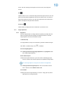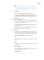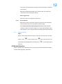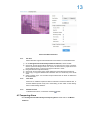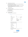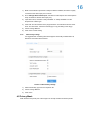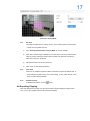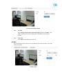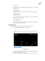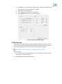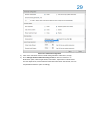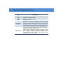
1
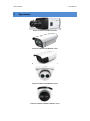
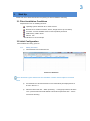
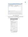
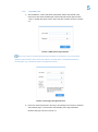
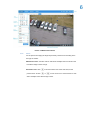
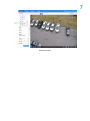
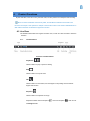
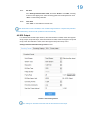
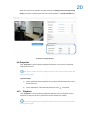
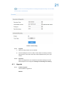
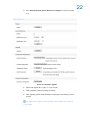
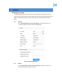
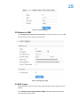
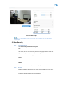
KEDACOM
User Manual for HD IP Camera of
IPC Series
Version 02
Trademark
Kedacom™ and
are trademarks of Suzhou Keda Technology Co., Ltd. in
China and various other countries. All other trademarks mentioned in this document are
the property of their respective holders.
Suzhou Keda Technology Co., Ltd.
131 Jinshan Road
New District, Suzhou, 215011
People's Republic of China
http://www.kedacom.com/en
Tel: +86-512-68418188
Fax: +86-512-68412699
© 2015 Suzhou Keda Technology Co., Ltd. All rights reserved.
Without the prior written permission of Suzhou Keda Technology Co., Ltd., any
reproduction, translation or retransmission of all or any part of this document for any
purpose in either electronic or mechanical form is not allowed.
Notice
The information in this document is subject to change without notice. Every effort has
been made in the preparation of this document to ensure accuracy of the contents, but all
statements, information, and recommendations in this document do not constitute a
warranty of any kind, express or implied. Suzhou Keda Technology Co., Ltd. is not
responsible for printing or clerical errors.
Target Audience
Administrators and Operators of Video Surveillance Products
Document Version
Version 02
Applicable Models
IPC113 series, IPC123 series
IPC2151 series, IPC2251 series
IPC2152 series, IPC2252 series
IPC2110 series, IPC2210 series
IPC2111 series, IPC2211 series, IPC2411 series
Related Document
Quick Start Guide
Convention
Icon
italic
>
BOLD
Convention
Notes
Book or document name;
Filling content
Connector between menus of different level
Menu; Button; Option
Contents
© 2015 Suzhou Keda Technology Co., Ltd. All rights reserved. ......................................................... 2
Notice ....................................................................................................................................................... 2
Target Audience ...................................................................................................................................... 3
1.
Product Brief ................................................................................................................................... 1
2.
Appearance ..................................................................................................................................... 2
3.
Start Up............................................................................................................................................ 3
4.
3.1
Client Installation Conditions ................................................................................................ 3
3.2
Initial Configuration .............................................................................................................. 3
3.2.1
Modify Parameter ........................................................................................................ 3
3.2.2
Login Web Client ......................................................................................................... 5
3.2.3
Focus ........................................................................................................................... 6
Product Functions .......................................................................................................................... 8
4.1
4.2
Live View .............................................................................................................................. 8
4.1.1
Toolbar Buttons ........................................................................................................... 8
4.1.2
Image Adjustment ...................................................................................................... 10
4.1.3
Auxiliary Function ...................................................................................................... 12
Motion Detection ................................................................................................................ 12
4.2.1
Set Area ..................................................................................................................... 13
4.2.2
Clear Area.................................................................................................................. 13
4.2.3
Disable Function ........................................................................................................ 13
4.3
Tempering Alarm................................................................................................................ 13
4.4
Alarm Linkage .................................................................................................................... 14
4.4.1
Motion Detection Alarm Linkage ................................................................................ 15
4.4.2
Tempering Alarm Linkage .......................................................................................... 15
4.4.3
Alarm Input Linkage ................................................................................................... 15
4.4.4
4.5
4.6
4.7
Privacy Mask ...................................................................................................................... 16
4.5.1
Set Area ..................................................................................................................... 17
4.5.2
Clear Area.................................................................................................................. 17
4.5.3
Disable Function ........................................................................................................ 17
Encoding Clipping .............................................................................................................. 17
4.6.1
Set Area ..................................................................................................................... 18
4.6.2
Clear Area.................................................................................................................. 18
ROI..................................................................................................................................... 18
4.7.1
Set Area ..................................................................................................................... 19
4.7.2
Clear Area.................................................................................................................. 19
4.8
SDI Output ......................................................................................................................... 19
4.9
Snapshot ............................................................................................................................ 20
4.10
Playback ............................................................................................................................ 20
4.11
5.
Abnormality Linkage .................................................................................................. 16
4.10.1
Playback ................................................................................................................ 21
4.10.2
Download............................................................................................................... 21
Upgrade ............................................................................................................................. 21
4.11.1
Firmware Upgrade ................................................................................................. 21
4.11.2
Web Client Upgrade .............................................................................................. 23
Settings ......................................................................................................................................... 24
5.1
Network Access ................................................................................................................. 24
5.1.1
Ethernet ..................................................................................................................... 24
5.1.2
PPPoE ....................................................................................................................... 24
5.2
Register to VMS ................................................................................................................. 25
5.3
BNC Output ........................................................................................................................ 25
5.4
User Security...................................................................................................................... 26
6.
5.4.1
User Management ..................................................................................................... 26
5.4.2
IP Filter ...................................................................................................................... 26
5.5
Text Overlay ....................................................................................................................... 27
5.6
Multi-stream ....................................................................................................................... 28
Appendix: Glossary of Terms ...................................................................................................... 31
HD IP Camera
1.
User Manual
Product Brief
HD IP Camera (hereinafter referred to as Camera) is a remote video surveillance device based on IP
network technology. It encodes and transmits HD video.
Some features of the HD IP camera:
Live View
Apply high-performance progressive scan sensor, with clear image and vivid color;
High-performance video processing chip and efficient video encoding, providing HD video image;
Dual-stream to fit different network bandwidth;
Configurable text overlay on video image;
Alarm
With audio and alarm connectors, realize functions of talkback and alarm;
Motion detection and alarm linkage, make video surveillance intelligent;
Support alarm linkage edit: Alarm Text Overlay, Device Output, Live View Display and etc.
Networking
Static address, DHCP or PPPoE;
NAT traversal, DNS and multicast technology
Storage
With SD card slot, when the network breaks down, video can be stored in local SD card;
Support local snapshot, default format is .JPG;
Support local recording, user can query and playback recording on PC.
HD IP Camera
2.
User Manual
Appearance
Picture 2-1 IPC113 and IPC123 series
Picture 2-2 IPC2151 and IPC2251 series
Picture 2-3 IPC2152 and IPC2252 series
Picture 2-4 IPC2110 and IPC2210 series
Picture 2-5 IPC2111/ IPC2211/ IPC2411 series
3
3.
Start Up
Please refer to the Quick Start Guide in the packing for device installation and wiring.
3.1 Client Installation Conditions
Requirements of PC for installing the client:
Operating System: Windows XP or newer versions
Browser: IE7.0 and above versions, Firefox, Google Chrome (41 and below)
Processor: 3.3 GHz CORE®i3 series or other equivalent processors
RAM Memory: 4GB or above
DirectX:9.0c
We will take IE7.0 as an example.
3.2 Initial Configuration
After installation and wiring, power on.
3.2.1
1)
Modify Parameter
Get IPCSearch from the attached CD.
Picture 3-1 IPCSearch
Note: IPCSearch is green software free from installation. Camera name is subject to the search
result.
2)
Run IPCSearch: it will search devices in LAN automatically and display the list as
shown in Picture 3-1.
3)
Select the device and click “Batch processing”. In the popup interface, set admin
user’s password and the email address to find back the password. Click “Active”
and wait for rebooting.
4
Picture 3-2 Batch processing
4)
Select a camera to be configured, click “Modify Params” or right click the mouse.
Interface is shown in Picture 3-3. During the modification, the user name (admin)
and the password set before activation should be entered.
Picture3-3 Modify Parameter
5
3.2.2
1)
Login Web Client
After modification, camera will reboot automatically. Please wait patiently. After
reboot, the button will be enabled again. Please select this device again and click
“Login” or double click device name to enter web client. Interface is shown in Picture
3-4.
Picture 3-4 Web Client Login Interface
Note: If log in the non-activated device through web client for the first time, user can set admin
password and activate the device in the login interface, as shown below. Complicated password is
recommended, e.g. combination of letters and digits above 8 bits.
Picture 3-5 First login through web client
2)
Enter user name and password: when log in successfully for the first time, download
and install the plug-in. Close browser when installing and re-login afterwards.
Interface after login is shown in Picture 3-6.
6
Picture 3-6 Web Client Interface
3.2.3
Focus
It is the process of imaging the target object clearly. Please focus according to the
lens type of camera:
Mechanical Focus: View live video on web client and adjust the focus knob on the
lens till the image is clear enough.
Electrical Focus: Click
picture shows. Or click
in function buttons area of the web client, as the
or
for near or far focus. View live video on web
client and adjust focus till the image is clear.
7
Picture 3-7 Focus
8
4.
Product Functions
By the web client, user can not only view live video, but also perform local snapshot and recording.
Note: Functions of different cameras may differ, and this Manual will take camera with more
functions as example. User operation is subject to the actual functions of the model. Disabled button in
Web Client means the model doesn’t support the function.
4.1 Live View
The default interface after user login is live video view, or user can click Live View to enter the
interface.
4.1.1
Toolbar Buttons
Picture4-1 Toolbar Buttons
Play/Pause
/
Click this button to play or pause a viewing.
Stop
Click this button to stop live view.
Call
Click this button to call camera, and click again to stop calling. Not all cameras
support this function.
Snapshot
Click this button to snapshot an image.
Snapshot includes Camera Snapshot
in Settings>Local.
and Local Snapshot
. User can set
9
Recording
Click this button to start recording and click again to stop recording. Recording is
saved on local PC. User can set or modify save path in Settings>Local.
Note: 1) Camera Snapshot: Camera snapshots an image and sends it to local client
in .JPG format. The image quality is good, but there is some time delay caused by network.
2) Local Snapshot: Client snapshots an image and save it locally. The image
quality is ordinary, but there isn’t any time delay.
Picture 4-2 Snapshot Setting
EPTZ
Click this button to enable the e-PTZ function. Left click and drag toward lower right
to draw an area. The pixels of this area will be amplified and will cover the whole
10
screen. Left click and drag toward upper left to draw an area, then image will
recover.
PTZ
Click the button to zoom. Left click and drag toward lower right to draw an area. The
pixels of this area will be amplified and will cover the whole screen. Left click and
drag toward upper left to draw an area, then the image will recover. Double click a
point in the image and the point will be centered.
Full Screen
Click this button to display full screen. Double click or press Esc to exit.
4.1.2
Image Adjustment
4.1.2.1
Brightness
Due to low light situation, the image will look completely or partially dark and
hard to recognize. Web client provides the following functions to increase
image brightness and ensure surveillance quality.
*Enable IR Lamp
In low light situation, IR lamp can be started to get better surveillance images.
Click
to enable IR lamp. Click
to disable it.
Increase Image Brightness
Go to Settings>Camera>Image>Image Adjustment, drag Brightness slide
bar to adjust image brightness.
Slower Shutter Speed
Camera shutter speed means the cycle of the sensor calculating light input
amount. Therefore, the slower the speed is, the brighter the image will be.
Note: If the target object is moving fast, this method is not applicable.
Go to Settings>Camera>Image>Exposure, user can set shutter mode as
auto or manual, and set Shutter Lower Limit.
Increase Gain
Camera gain means the light sensitivity of a sensor. A high gain may reduce
light exposure for low light situation.
11
Note: However, the higher the gain is, the worse the image will be. User
is advised to select Auto for default values, or select Auto and set Gain
Upper Limit in Settings>Camera>Image. If user selects “Manual”, drag
the slide bar to adjust gain level.
*Enable WDR
WDR can provide optimal exposure in intense backlight conditions.
Go to Settings>Camera>Image>Image Enhancement, enable WDR in the
drop-down list of Dynamic Adjustment and drag the WDR Sensitivity slide
bar to adjust.
4.1.2.2
White Balance Adjustment
The basic conception of White Balance is “to make all colors white regardless
of the color temperature of the light source”. It can compensate color rendition
in pictures taken in specific light source.
Go to Settings>Camera>Image>White Balance, select white balance mode
from the drop-down list.
If select “Manual”, drag the slide bar of White Balance R Gain (Red Gain) and
White Balance B Gain (Blue Gain) to adjust image color.
4.1.2.3
Night Cut
Day (Night) Mode means disabling (enabling) IR lamp (only some models
support), and the image switches to color (B/W), thus to get optimal images
for day (sufficient light source) and night (insufficient light source) conditions.
Go to Settings>Camera>Image>Night Cut, select Night Cut mode.
Day
Select Day mode, disable IR lamp (only some models support), and the image
is colored.
Night
Select Night mode, enable IR lamp (only some models support), and the image
is black and white.
Auto (Gain Triggered)
Select Auto mode and configure sensitivity and switch time, then the system
will switch Day/Night modes automatically.
Scheduled Day/Night
12
In this mode, camera switches to day/night mode automatically in a specified
period of time.
When select Scheduled Day/Night mode, click Edit Time, and check Start
Time and End Time in the popup interface.
Alarm Triggered Cut
In this mode, night cut is triggered by alarm input.
4.1.2.4
Noise Reduction
When there are many noise points caused by environment and camera lens,
Noise Reduction function can be enabled to adjust images.
Go to Settings>Camera>Image>Image Enhancement, enable 3D Noise
Reduction. When user selects “Disable”, the function will be disabled. When
select “Enable”, user can drag the slide bar to adjust 3D noise reduction level.
4.1.3
Auxiliary Function
*Wiper
Wiper is used to clean the dome housing. In the PTZ control part of the Live View
interface, Click
to start the wiper. Click
wiper will stop automatically after 10 brushes. Click
again to stop the wiper. The
to enable wiper again if
necessary.
4.2 Motion Detection
Detect movements in the defined area. Once the movement exceeds the defined sensitivity,
an alarm will be triggered by Web Client.
13
Picture 4-3 Motion Detection
4.2.1
Set Area
Motion detection supports full area detection and maximum 4 user-defined areas.
1)
2)
3)
4)
5)
6)
4.2.2
Go to Settings>Event>Video Analysis>Motion Detection, check “Enable”.
Click “Edit” and the image will be divided into 16 columns and 12 rows of squares.
Click a square and drag an area from it, then the area will turn purple and is the
motion detection area. A camera can support maximum 4 areas.
Drag the slide bar to adjust Sensitivity.
Click “Edit”. On the popup page, check durations and set start time and end time.
Click “Copy” to copy the defined motion detection time to a certain day or the whole
week.
Select “Linkage Type”. It is the alarm output method when an alarm is detected in
the defined area.
Clear Area
Start from an undefined square and draw an area that contains the defined area, or
click the defined squares one by one to clear setting, or click “Clear” to clear setting.
Save to make settings effective.
4.2.3
Disable Function
To disable this function, uncheck the checkbox
Enable.
4.3 Tempering Alarm
Go to Settings>Event>Video Analysis>Tempering Alarm. Please refer to 4.2 Motion
Detection.
14
Picture 4-4 Shield Area Alarm
4.4 Alarm Linkage
Alarm Linkage is the system reaction after an alarm signal is received. It is to raise watch
man’s attention to handle the event.
The alarm signal comes from Motion Detection (details in Chapter 4.2) or Alarm Input Device
(such as smoke detector) in the surveillance area.
Alarm Linkage reaction includes Alarm Text Overlay, Snapshot or triggering alarm output
device (such as alarm bell). Explanations are as follows:
Report to Management System: when alarm is triggered, report to the central surveillance
system.
Text Overlay: when alarm is triggered, display alarm text on screen.
Acoustic Alarm: when alarm is triggered, make a warning sound.
Recording Linkage: when alarm is triggered, start to record video automatically.
Snapshot: when alarm is triggered, take a snapshot of the alarm event.
Alarm Output: when alarm is triggered, link to the alarm output device.
15
4.4.1
1)
Motion Detection Alarm Linkage
Enable Motion Detection, and set the detection area and sensitivity. Please refer to
Chapter 4.2 Motion Detection for details.
2)
Check the Linkage Type for motion detection. For example, if user checks Snapshot,
when alarm is triggered, the system will take a snapshot. In
Settings>Storage>Snapshot interface, user can set picture format, resolution,
interval and quantity.
4.4.2
1)
Tempering Alarm Linkage
Enable Tempering Alarm, and set the area and sensitivity. The method is the same
as that of Motion Detection.
2)
Check Linkage Type.
3)
Click “Save” to finish setting.
4.4.3
Alarm Input Linkage
The camera supports on/off alarming device.
Picture 4-5 Alarm Input
16
1)
Make sure the alarm input device is always enabled or disabled, and that it is rightly
connected to the alarm input port of camera.
2)
Go to Settings>Event>Alarm Input, and select an alarm input ID from the dropdown
list (in accordance with the alarm input port).
3)
Input alarm name, and select “Always Enabled” or “Always Disabled” from the
dropdown list of alarm type.
4)
Click “Edit” and set durations at the popup interface. Check durations and set “Start
Time” and “End Time”. Check the week day(s) to copy the setting to the day(s).
5)
Check “Linkage Method”.
6)
Click “Save” to finish setting.
4.4.4
Abnormality Linkage
It is triggered when something abnormal happens. Abnormality includes Disk Full,
Disk Error and Internet Disconnected.
Picture 4-6 Abnormality Linkage
1)
Select Abnormality Type from the dropdown list.
2)
Check “Linkage Method”.
3)
Click “Save”.
4.5 Privacy Mask
Mask sensitive and private part of the image so as to keep sensitive information private.
17
Picture 4-7 Privacy Mask
4.5.1
Set Area
The image is divided into 16 columns and 12 rows of small squares. The maximum
number of Privacy Mask area is 4.
1)
Go to Settings>Camera>Video >Privacy Mask, and check “Enable”.
2)
Click “Edit”, and the image is divided into 16 columns and 12 rows of small squares.
Click any square and drag an area from this square, then this area is the privacy
mask area, which is in purple red.
3)
Select Mask Color from the drop-down list.
4)
Click “Save” to make settings effective.
4.5.2
Clear Area
Start from an undefined square and draw an area that contains the defined area, or
click the defined squares one by one to clear setting, or click “Clear” directly. Click
“Save” to make settings effective.
4.5.3
Disable Function
To disable this function, uncheck
Enable.
4.6 Encoding Clipping
After user defines the encoding area, the system will encode and display the clipping area
only, so as to save system resources and network bandwidth.
18
Picture 4-8 Encoding Clipping
4.6.1
Set Area
Go to Settings>Camera>Video >Encoding Clipping, and check “Enable”. Click
“Edit”, and drag an area as the clipping area. Click “Save” to make settings
effective.
4.6.2
Clear Area
Click “Clear” to clear edition and reset area.
4.7 ROI
Only encode specific area to ensure normal surveillance and constant resolution of key area
under poor network.
Picture 4-9 ROI
19
4.7.1
Set Area
Go to Settings>Camera>Video >ROI, and check “Enable”. Click “Edit”, and drag
an area as the clipping area. Select encoding grade from the dropdown list. Click
“Save” to make settings effective.
4.7.2
Clear Area
Click “Clear” to clear edition and reset area.
Note: When ROI Encode is enabled, if user modifies image resolution or aspect ratio (standard
screen/widescreen), the device will quit ROI Encode automatically.
4.8 SDI Output
For cameras with HD-SDI output function, when the resolution is 1080P, frame rate supports
25 fps, 30 fps, 50 fps and 60 fps; when the resolution is 1080i, frame rate supports 50 fps and
60 fps; when the resolution is 720P, frame rate supports 50 fps and 60 fps. Go to
Settings>Camera>Video>Encoding Format and set.
Picture 4-10 Encoding Format
Note: Settings on resolution and frame rate are also effective to SDI output.
20
When user wants to set resolution as 1080i, please go to Settings>Camera>Image>Image
Quality, and select “Interlacing (same as main stream resolution)” in Rotate and BNC part.
Picture 4-11 Image Quality
4.9 Snapshot
Click “Snapshot” to enter snapshot management interface. User can view or download
snapshots in SD card.
Note: If the Snapshot interface is disabled, please confirm the SD card is inserted and
then login client again.
Operation Steps
1)
Search snapshots: search snapshots in accordance with the duration and format
from the SD card.
2)
4.10
On the snapshot list, select searched picture and click
to download
Playback
Click “Playback” to enter recording management interface. User can playback, clip and
download recordings in SD card. (A SD card must be inserted in the camera.)
Note: If the Playback interface is disabled, please confirm the SD card is inserted and
then login client again.
21
Note: User can set recording durations in Settings>Storage>Recording. Check “Enable”
and click “Edit” to set durations.
Picture 4-12 Recording
4.10.1
Playback
1)
Select recording duration from the calendar.
2)
If there is background color on a date, it means there is recording on that day.
Select duration of the date and the video will be displayed directly in the right
window.
4.10.2
Download
Select recording duration from calendar and download recording to local PC.
Download path can be configured in Settings>Local Setting>Local Setting.
4.11
Upgrade
4.11.1
Firmware Upgrade
Contact dealer for upgrade file.
Method 1
22
1)
Go to Settings>System>System Maintenance>Upgrade, as shown in Picture
4-13.
Picture 4-13 Firmware Upgrade
2)
Select local upgrade file (<*.pkg> or <*.img> format).
3)
During upgrading, please do nothing but waiting.
4)
After upgrading, please download ActiveX control again. After finishing it, reboot
browser.
Note: Please click “Upgrade” when upgrading, and the upgrade file is usually in
<*.pkg> format.
23
Method 2
1)
Run IPCSearch.
2)
Click “Upgrade” to upgrade firmware of cameras of the same model
simultaneously.
4.11.2
Web Client Upgrade
After firmware upgrade, please login web client again. The page will prompt to
download a new ActiveX control. After downloading it, client upgrade will be
completed. Login again to enter the latest Web Client.
Note: For detailed operation instructions of Web Client, please refer to the help
document.
24
5.
Settings
5.1 Network Access
3.2 Initial Configuration has introduced how to modify parameters via IPCSearch to make
camera access network. Camera accepts multiple network access methods (via Ethernet and
PPPoE). The following introduces how to configure camera network parameters in Web
Client.
5.1.1
Ethernet
Go to Settings>Network>IP and Port>IP Address, as shown in Picture 4-1 to
configure IP address, subnet mask and default gateway.
Picture 5-1 Ethernet Parameter
5.1.2
PPPoE
Go to Settings>Network>Other Protocols>PPPOE, as shown in Picture 5-2 to
enter user name and password, and save.
25
Picture 5-2 PPPoE Setting
5.2 Register to VMS
Go to Settings>Network>Access Protocol>VSIP, as shown in Picture 5-3 to enter VMS
address and port. Save settings and reboot device.
Picture 5-3 Register to VMS
5.3 BNC Output
Camera with BNC output can output analog image directly when local display function is
enabled.
Go to Settings>Camera>Image>Rotate and BNC, select BNC output mode from the
drop-down list, as shown below.
26
Picture 5-4 BNC Output
Note: For cameras with HD-SDI output, when BNC is enabled, the web client will stop
image output.
5.4 User Security
5.4.1
User Management
Go to Settings>System>User Security>User.
Add:
Click “Add”, and enter user name and password in the popup interface. Select user
type from the dropdown list, and assign operation rights to newly added user from
the Authorization List. After setting, click “Confirm”.
Delete:
Select user IP and click “Delete” to delete the user.
Modify:
Select user IP and click “Modify” to modify in the popup interface.
5.4.2
IP Filter
By setting IP address filtering, user can manage access limitation to the web client.
White List includes IP addresses able to access to the client, while Black List
includes IP addresses unable to access to the client.
27
Enable IP Filter:
Select filter method from the dropdown list according to request, or select “Disable”
to disable IP filter.
Add Black/White List:
After select filter method, click “Add” and input IP address in the popup interface,
and click “Confirm”.
Modify Black/White List:
Select the IP address from the list and click “Modify” to modify the IP address in the
popup interface, and click “Confirm”.
Delete Black/White List:
Select the IP address from the list and click “Delete” to delete the IP address. Click
“Delete All” to clear all the IP addresses.
5.5 Text Overlay
Display preset text on the surveillance window, configuration steps as follows:
1)
Go to Settings>Camera>OSD, as shown in Picture 5-5.
Picture 5-5 OSD
2)
Check the options and preview the result in the window. For example, if user checks
“Time”, time will be displayed in the window.
3)
Edit positions: drag the items in the window with mouse to change their positions.
28
4)
Edit OSD texts: for example, if user checks OSD1, double click OSD1 textbox and
input characters in the popup interface. Click “OK”.
5)
Click “Save” to save OSD setting.
6)
Click “Load” to load default font or China GB font.
7)
Click “Advanced” to set “Format”, “Font” and “Margin”.
Picture 5-6 Advanced Setting of OSD
5.6 Multi-stream
Camera supports multiple streams encoding and decoding. Multi-stream means the same
video source is encoded into different streams of videos with different resolutions. User can
select proper resolution to view or record according to the network bandwidth.
Note: Different camera models may have different numbers of streams.
Operation steps:
1)
Go to Settings>System>System Maintenance; click “Configuration” under “Advanced
Configuration”, and input password;
2)
Select working mode from the dropdown list;
29
Picture 5-7 Advanced Configuration
3)
Click “Save” and reboot camera to make setting take effect. After reboot, re-login;
4)
Go to Settings>Camera>Video>Encoding Format, as shown in Picture 5-8. In
Multi-stream option, select Single Stream, Dual-stream, Triple-stream or Quad-stream
from the dropdown list, and the selection takes effect after reboot. After enable, user can
set parameters below the option accordingly.
30
Picture 5-8 Stream Type
6.
Appendix: Glossary of Terms
Term
720P
CIF
QCIF
ROI
Key Frame
Interval
Quantization
Explanation
Resolution of 1280*720 pixels
Resolution of 352*288 pixels
Resolution of 176*144 pixels
Region Of Interest
Key Frame defines the important frame when change
happens in a video. This frame will be completely
encoded. Key Frame Interval defines the maximum frames
during the interval between key frames. If the video
changes quite frequently, shorter Key Frame Interval will
make video more real, but it will take more bandwidth.
Set Min. and Max. Quantization, and image compression
quantization will fluctuate in the range.
During image compression, larger quantization brings
higher compression ratio and higher distortion ratio. On
the contrary, smaller quantization brings lower
compression ratio and better image recovery, but
meanwhile takes more bandwidth.