1
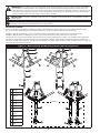
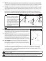
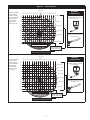
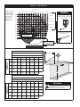
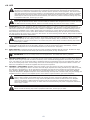
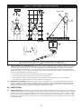
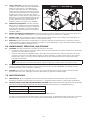
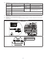
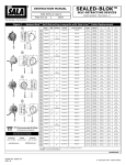
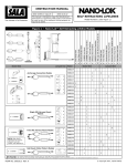
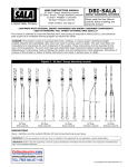
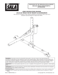
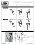
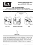
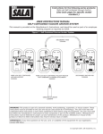
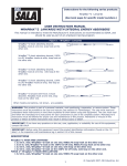
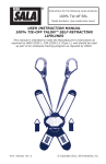
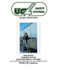
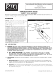
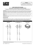
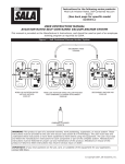
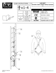
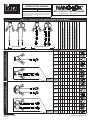
INSTRUCTION MANUAL
ANSI Z359.14 Class B
ANSI A10.32
This manual is intended to meet the Manufacturer’s
Instructions as required by ANSI Z359.14 and should
be used as part of an employee training program as
required by OSHA.
The Ultimate in Fall Protection
Self Retracting Lanyards
Model Numbers: (See Figure 1)
Model
Single SRL-LE Nano-Lok Edge Models
3500210
1
1
1
3500214
1
3500215
1
3500216
1
3500247
1
3500248
3500226
Twin SRL-LE Nano-Lok Edge Models
1
3500213
3500225
3500227
3500229
3500230
3500231
3500249
3500246
3500228
9501804 WrapBax Alloy Steel Rebar Snap Hook
1
3500212
WrapBax
2109193 Alloy Steel Rebar Snap Hook
9502058 Aluminum Alloy Rebar Snap Hook
2000209 Aluminum Alloy Rebar Snap Hook
9505254 Aluminum Alloy Snap Hook
Connectors - Lanyard End
3500211
WrapBax
Form no: 5903543
Rev: C
2000023 Aluminum Alloy Captive Eye Carabiner
2000210 Alloy Steel Rebar Snap Hook
Nano-Lok Edge WrapBax
9502195 Alloy Steel Swiveling Snap Hook
Nano-Lok Edge
9502116 Alloy Steel Snap Hook
Figure 1 – Nano-Lok™ Edge Self Retracting Lanyard Models
2
2
2
2
2
2
2
2
2
© Copyright 2013, Capital Safety
WARNING: This product is part of a personal fall arrest, work positioning, or rescue system. The user must follow
the manufacturer’s instructions for each component of the system. These instructions must be provided to the user
of this equipment. The user must read and understand these instructions before using this equipment. Manufacturer’s
instructions must be followed for proper use and maintenance of this equipment. Alterations or misuse of this product
or failure to follow instructions may result in serious injury or death.
IMPORTANT: If you have questions on the use, care, or suitability of this equipment for your application, contact
i
Capital Safety.
i
IMPORTANT: Before using this equipment, record the product identification information from the ID label and iSafe
RFID tag in the inspection and maintenance log of this manual.
descriptionS:
igure 2 illustrates key components of Nano-Lok Edge™ Self Retracting Lanyards (SRL-LEs). The standard SRL-LEs contain
F
8 ft. (2.44 m) long galvanized wire rope lifelines of which 6 ft (1.82 m) retracts within the SRL-LE housing.
WrapBax™ SRL-LEs contain 6 ft. (1.8 m) long galvanized wire rope lifelines which retract within the SRL-LE housing.
WrapBax™ SRL-LEs have an additional 3 ft (.91 m) long web section that is used to attach to an anchorage.
The SRL-LEs are mounted at the dorsal D-ring location of the users full body harness. Models are available in both single and
twin SRL-LE configurations which incorporate several snap hook, carabiner and WrapBax™ attachment options. The SRL-LEs
include an integral energy absorber. The SRL-LEs automatically lock at the onset of a fall to arrest the falling worker, but pay out
and retract during normal movement.
Figure 2 – Nano-Lok Edge Self Retracting Lifeline (SRL-LE) Components
A
A
B
B
G
B
G
H
H
C
C
xxxxxx
xxxxx
xxxxxx
xxxxx
I
I
I
I
D
D
E
E
F
A
Harness
Interface
B
Housing
C
Energy
Absorber
Cover
D
Cable Lifeline
E
Cable Guide
Bumper
F
Snap Hook
G
iSafe™ RFID
Tag
H
Instruction
Labels
I
Hook and Loop
Straps
J
WrapBax
Webbing
K
WrapBax Snap
Hook
F
xxxx
xxxx
xxxx
xxxx
xxx
xxx
WrapBax™
J
J
K
K
2
J
K
1.0APPLICATIONS
1.1PURPOSE: DBI/SALA Nano-Lok Edge™ Self Retracting Lanyards with leading edge capability (SRL-LEs) are designed
for use in applications where falls may occur, including falls over edges, such as roofing, leading edge construction, etc.
SRL-LEs are designed to be a component in a personal fall arrest system (PFAS). Figure 1 illustrates the SRL-LEs covered
by this manual. SRL-LEs may be used in many situations where a combination of worker mobility and fall protection is
required (i.e. inspection work, general construction, maintenance work, oil production, confined space work, etc.). The
twin Nano-lok Edge models incorporate two SRL-LE units that can be used for applications where 100% tie-off is required.
1.2Standards: Nano-lok Edge SRL-LEs conform to the national standard(s) identified on the ID label. Refer to local, state,
and federal (OSHA) requirements governing occupational safety for additional information regarding Personal Fall Arrest
Systems. Refer to the following national standards on fall protection:
ANSI
Z359.0
Definitions and Nomenclature Used for Fall Protection and Fall Arrest
ANSI
Z359.1
Safety Requirements for Personal Fall Arrest Systems, Subsystems, and Components
ANSI
Z359.2
Minimum Requirements for a Comprehensive Managed Fall Protection Program
ANSI
Z359.14
Safety Requirements for Self-Retracting Devices for Personal Fall Arrest and Rescue Systems
ANSI
A10.32
Personal Fall Protection use in Construction and Demolition
1.3Training: This equipment is intended to be used by persons trained in its correct application and use. It is the responsibility of the
user to assure they are familiar with these instructions and are trained in the correct care and use of this equipment. Users must be
aware of the operating characteristics, application limits, and the consequences of improper use.
2.0 Limitations & Requirements
Always consider the following limitations and requirements when installing or using this equipment:
2.1Capacity: The DBI/SALA Nano-Lok Edge Self Retracting Lanyard with Leading Edge capability (SRL-LE) is designed for
use by one person with a combined weight (person, clothing, tools, etc.) of up to 310 lbs (141 kg) for all applications including
Leading Edge. The DBI/SALA Nano-Lok Edge Self Retracting Lanyard may be used for capacities up to 420 lbs (190 kg) in
limited applications but not for Leading Edge. See Section 2.12 and associated figures for use restrictions.
2.2ANCHORAGE: Anchorages selected for fall arrest systems shall have a strength capable of sustaining static loads applied
in the directions permitted by the system of at least:
1. 5,000 lbs. (22.2 kN) for non-certified anchorages, or
2. Two times the maximum arresting force for certified anchorages.
When more than one fall arrest system is attached to an anchorage, the strengths set forth in Section 2.2 1. and 2.
above shall be multiplied by the number of systems attached to the anchorage.
From OSHA 1926.500 and 1910.66: Anchorages used for attachment of personal fall arrest systems shall be
independent of any anchorage being used to support or suspend platforms, and capable of supporting at least 5,000 lbs. per
user attached, or be designed, installed, and used as part of a complete personal fall arrest systems which maintains a safety
factor of at least two, and is under the supervision of a qualified person.
warning: The anchor point must be located at the same height or above the edge over which a fall might
occur. Workers over 310 lbs (141 kg) must not use these SRL-LEs where falls over edges may occur. Failure to
heed this warning may result in equipment malfunction, serious injury, or death.
2.3
Rescue plan: When using this equipment, the employer must have a rescue plan and the means at hand to implement
it and communicate that plan to users, authorized persons, and rescuers.
i
2.4
2.5
2.6
Note: Special rescue measures may be required for a fall over an edge.
Inspection Frequency: SRL-LEs shall be inspected by the authorized person1 or rescuer2 before each use.
Additionally, inspections shall be conducted by a competent person3 other than the user. The competent person
shall use the Nano-Lok Edge™ Self Retracting Lanyards Inspection Schedule and Checklist (Table 1) for appropriate
inspection intervals and procedures. Results of the Competent Person inspection should be recorded in the “Inspection and
Maintenance Log” on the back pages of these instructions or recorded with the i-Safe™ system (see Section 5).
Locking Speed: Situations which restrict the speed of a fall should be avoided. Working in confined or cramped spaces
may not allow the body to reach sufficient speed to cause the SRL-LE to lock if a fall occurs. Working on slowly shifting
material, such as sand or grain, may not allow enough speed buildup to cause the SRL-LE to lock. A clear path is required
to assure positive locking of the SRL-LE.
Normal operations: Normal operation will allow the full length of the lifeline to extend and retract with no hesitation
when extending and no slack when retracting as the worker moves at normal speeds. If a fall occurs, a speed sensing
brake system will activate, stopping the fall. An external energy absorber will activate during fall arrest to absorb much
of the energy created and reduce inpact forces. Sudden or quick movements should be avoided during normal work
operation, as this may cause the SRL-LE to lock up.
1 Authorized Person: A person assigned by the employer to perform duties at a location where the person will be exposed to a fall hazard.
2 Rescuer: Person or persons other than the rescue subject acting to perform an assisted rescue by operation of a rescue system.
3 Competent Person: An individual designated by the employer to be responsible for the immediate supervision, implementation, and monitoring of the employer’s managed fall protection program who, through training and knowledge, is capable of identifying, evaluating, and addressing existing and potential fall hazards,
and who has the employer’s authority to take prompt corrective action with regard to such hazards.
3
2.7
Free fall: When anchored overhead, SRL-LEs will limit the free fall distance to 2 ft. (61 cm) or less. To avoid increased fall
distances, anchor the SRL-LE directly above the work level. Avoid working where your lifeline may cross or tangle with that
of another worker. Avoid working where an object may fall and strike the lifeline; resulting in loss of balance or damage to
the lifeline. Do not allow the lifeline to pass under arms or between legs. Never clamp, knot, or prevent the lifeline from
retracting or being taut. Avoid slack line. Do not lengthen SRL-LE by connecting a lanyard or similar component.
2.8Hazards: Use of this equipment in areas where surrounding hazards exist may require additional precautions to reduce
the possibility of injury to the user or damage to the equipment. Hazards may include, but are not limited to: high heat,
caustic chemicals, corrosive environments, high voltage power lines, explosive or toxic gases, moving machinery, sharp
edges, or overhead materials that may fall and contact the user or fall arrest system.
2.9
Sharp Edges: The Nano-Lok Edge Self Retracting Lanyard has been successfully tested for horizontal use and for falls
over a steel edge without burrs. As a result, the Nano-Lok Edge may be used in situations where a fall may occur over
similar edges such as those found on steel shapes or metal sheeting. Tie-off (anchorage) level restrictions shown in
Figures 5 and 6 must be observed. Avoid working where the lifeline will continuously or repeatedly abrade against sharp
or abrasive edges. Eliminate such contact or protect edges using a heavy pad or other means.
warning: The allowable angle
of redirection of the lifeline at the
edge over which a fall might occur
(see Figure 3 A, B and C.), measured
between the two sides formed by the
redirected lifeline (B in Figure 5D),
must be at least 90 degrees. In other
words, working above the level at which
the SRL-LE is anchored (example:
Figure 3 C) and being exposed to an
edge hazard is dangerous because this
will cause the lifeline to “redirect” at a
sharper angle if a fall occurs and may
cut or damage the lifeline. Failure to
heed this warning may result in serious
injury or death.
Figure 3 – Allowable Angle of Redirection
C
A
OK
B
OK
NO
warning: Do not work on the far side of an opening, opposite the SRL-LE anchorage point. Failure to heed this
warning may result in serious injury or death.
2.10 Body Support: A Full Body Harness must be used with the SRL-LE. The harness
connection point must be above the user’s center of gravity just below the harness
back dorsal D-Ring. A body belt is not authorized for use with the Nano-Lok Edge
SRL-LE. A fall occuring when using a body belt may cause unintentional release and/
or injuries due to improper body support.
Figure 4 – Swing Falls
2.11 Swing Falls: Swing falls occur when the anchorage point is not directly above
the point where a fall occurs (see Figure 4). The force of striking an object in a
swing fall may cause serious injury. In a swing fall, the total vertical fall distance
will be greater than if the user had fallen directly below the anchorage point, thus
increasing fall clearance required to safely arrest the user. Use Figures
5A through 5D (6A through 6D for WrapBax) to determine the fall clearance for
your application. Minimize swing falls by working as directly below the anchorage
point as possible. Never permit a swing fall if injury could occur.
2.12fALL cLEARANCE: Figures 5A through 5D and 6A through 6D illustrate Fall
Clearance requirements. Ensure adequate clearance exists in the fall path to prevent
striking an object during a fall. If a user is working at a position that is not directly
below the SRL-LE anchorage point, the clearance required and vertical fall distance
increase. Figures 5D and 6D provide the clearance requirements when using the SRLLE for leading edge applications.
Determine Fall Clearance Required: To determine the fall clearance required, measure the distance from the
user’s harness dorsal connection to the anchorage for the SRL-LE. Both horizontal and vertical distances are required.
Use Figures 5A through 5D and 6A through 6D, depending on user total weight, to determine the required clearance.
The dotted lines in the figures represent 1 foot (0.3 m) increments from the user’s harness dorsal connection to the
anchorage. For example, 8 ft (2.4 m) of clearance is required when the SRL-LE unit is anchored 3 1/2 ft (1 m) above and
3 1/2 ft (1 m) to the side of the user’s harness dorsal connection for users up to 310 lbs (141 kg) and 10 ft (3 m) for
users 310 lbs (141 kg) to 420 lbs (191 kg).
warning: The clearances provided above assume the fall occurs from the standing position. If the worker is
kneeling or crouching an additional 3 ft (0.9 m) of clearance is needed. Failure to heed this warning may result in
serious injury or death.
warning: Users between 310 and 420 lbs (141-191 kg): Users with a combined weight (person, clothing, tools,
etc.) of 310 lb to 420 lb (141-191 kg) must never anchor the Nano-Lok more than 2 ft (0.6 m) below their harness
dorsal connection. See Figure 5C and 6C. Failure to heed this warning may result in serious injury or death.
4
Figure 5 – Fall Clearance
Figure 5A: User Total Weight up to 220 lbs (100 kg).
6 ft (1.8 m)
Clearance required
in feet (meters)
between working
level and nearest
obstruction for
user with total
weight up to
220 lbs (100 kg).
WrapBax
Configuration
ft
6
5
4
4
5
6
8
7
3
3
8
7
2
1
1
2
(2.4) (2.1) (1.8) (1.5) (1.2) (0.9) (0.6) (0.3) (m) (0.3) (0.6) (0.9) (1.2) (1.5) (1.8) (2.1) (2.4)
8
(2.4)
7
(2.1)
6
(1.8)
5
(1.5)
4
(1.2)
3
(0.9)
2
(0.6)
1
(0.3)
ft
(m)
1
(0.3)
2
(0.6)
3
(0.9)
4
(1.2)
5
(1.5)
8 ft (2.4 m)
See Figure 5A
WrapBax webbing wrapped
around anchor.
10 ft (3.0 m)
12 ft (3.7 m)
14 ft (4.3 m)
16 ft (4.9 m)
18 ft (5.5 m)
For straight connection of a
Wrapbax hook to an anchor,
see Figure 6A.
tion
nec
n
t Co
igh
Stra
Do Not Tie Off Below Feet
Clearance between
Working Level and
Nearest Obstruction
Figure 5B: User Total Weight up to 310 lbs. (141 kg)
7 ft (2.1m)
Clearance required
in feet (meters)
between Working
Level and Nearest
Obstruction for
User with total
weight up to 310
lbs. (141 kg)
WrapBax
Configuration
ft
6
5
4
4
5
6
8
7
3
3
7
8
2
1
1
2
(2.4) (2.1) (1.8) (1.5) (1.2) (0.9) (0.6) (0.3) (m) (0.3) (0.6) (0.9) (1.2) (1.5) (1.8) (2.1) (2.4)
See Figure 5B
8
(2.4)
8 ft (2.4 m)
7
(2.1)
6
(1.8)
5
(1.5)
4
(1.2)
3
(0.9)
2
(0.6)
1
(0.3)
ft
(m)
1
(0.3)
2
(0.6)
3
(0.9)
4
(1.2)
5
(1.5)
WrapBax webbing wrapped
around anchor.
10 ft (3.0 m)
12 ft (3.7 m)
14 ft (4.3 m)
16 ft (4.9 m)
18 ft (5.5 m)
20 ft (6.1 m)
Do Not Tie Off Below Feet
5
Clearance between
Working Level and
Nearest Obstruction
For straight connection of a
Wrapbax hook to an anchor,
see Figure 6B.
tion
nec
Con
ight
Stra
Figure 5 – Fall Clearance
Figure 5C: User Total Weight up to 420 lbs (191 kg)
8 ft (2.4 m)
Clearance required
in feet (meters)
between working
level and nearest
obstruction for
user with total
weight up to
420 lbs (191 kg).
ft
6
5
4
4
5
6
8
7
3
3
7
8
2
1
1
2
(2.4) (2.1) (1.8) (1.5) (1.2) (0.9) (0.6) (0.3) (m) (0.3) (0.6) (0.9) (1.2) (1.5) (1.8) (2.1) (2.4)
WrapBax
Configuration
10 ft (3.0 m)
8
(2.4)
See Figure 5C
12 ft (3.7 m)
7
(2.1)
6
(1.8)
5
(1.5)
4
(1.2)
3
(0.9)
2
(0.6)
1
(0.3)
ft
(m)
1
(0.3)
2
(0.6)
3
(0.9)
4
(1.2)
5
(1.5)
WrapBax webbing wrapped
around anchor.
14 ft (4.3 m)
16 ft (4.9 m)
18 ft (5.5 m)
20 ft (6.1 m)
For straight connection of a
Wrapbax hook to an anchor,
see Figure 6C.
Do Not Tie Off In
Dotted Area
tion
nec
Con
ight
Stra
Clearance between
Working Level and
Nearest Obstruction
Figure 5D: Edge Clearance, All Models Except WrapBax
Figure 4 – For Users Up To 220 lbs
Clearance Required (A) When Falling Over An Edge
C
Setback
Distance (C)
Distance Along Edge (B), ft (m)
0
1
2
0
14’-2”
(4.3)
14’-7”
(4.4)
15’-0”
(4.6)
15’-5” 15’-10” 16’-3”
(4.7)
(4.8)
(5.0)
16’-9”
(5.1)
1
13’-8”
(4.2)
14’-1”
(4.3)
14’-5” 14’-10” 15’-3” 15’-8”
(4.4)
(4.5)
(4.6)
(4.8)
16’-2”
(4.9)
2
13’-0”
(4.0)
13’-5” 13’-10” 14’-3” 14’-8” 15’-1”
(4.1)
(4.2)
(4.3)
(4.5)
(4.6)
15’-6”
(4.7)
3
12’-4”
(3.8)
12’-8”
(3.9)
14’-9”
(4.5)
4+
3
4
5
13’-1”
(4.0)
13’-6” 13’-11” 14’-5”
(4.1)
(4.2)
(4.4)
11’-6” 11’-11” 12’-4”
(3.5)
(3.6)
(3.8)
12’-9” 13’-3” 13’-8”
(3.9)
(4.0)
(4.2)
6
B
A
For Users Over 220 lbs, Up to 310 lbs
Clearance Required (A) When Falling Over An Edge
Setback
Distance (C)
Distance Along Edge (B), ft (m)
0
1
2
3
4
5
6
0
16’-0”
(4.9)
16’-6”
(5.0)
17’-0”
(5.2)
17’-7” 18’-2” 19’-10” 20’-0”
(5.4)
(5.5)
(6.0)
(6.1)
1
15’-6”
(4.7)
16’-0”
(4.9)
16’-6”
(5.0)
17’-0” 17’-8” 18’-6”
(5.2)
(5.4)
(5.6)
19’-3”
(5.9)
2
15’-0”
(4.6)
15’-6”
(4.7)
16’-0”
(4.9)
16’-6” 17’-2” 18’-0”
(5.0)
(5.2)
(5.5)
18’-6”
(5.6)
3
14’-6”
(4.4)
15’-0”
(4.6)
15’-6”
(4.7)
16’-0” 16’-6” 17’-0”
(4.9)
(5.0)
(5.1)
17’-6”
(5.3)
4+
14’-0”
(4.3)
14’-6”
(4.4)
15’-0”
(4.6)
15’-6” 16’-0” 16’-6”
(4.7)
(4.9)
(5.0)
6
WrapBax
warning: See setback distance for
WrapBax models. Refer to Figure 6D
for WrapBax edge clearance.
Figure 6 – Fall Clearance - WrapBax Snap Hook to Anchor, Straight Connection
Figure 6A: User Total Weight up to 220 lbs (100 kg).
6 ft (1.8 m)
Clearance required
in feet (meters)
between working
level and nearest
obstruction for
user with total
weight up to
220 lbs (100 kg).
9
(2.7)
8
(2.4)
7
(2.1)
8 ft (2.4 m)
ft
6
5
4
4
5
6
9
8
9
7
3
3
7
8
2
1
1
2
(2.7) (2.4) (2.1) (1.8) (1.5) (1.2) (0.9) (0.6) (0.3) (m) (0.3) (0.6) (0.9) (1.2) (1.5) (1.8) (2.1) (2.4) (2.7)
6
(1.8)
5
(1.5)
4
(1.2)
3
(0.9)
2
(0.6)
1
(0.3)
ft
(m)
1
(0.3)
2
(0.6)
3
(0.9)
4
(1.2)
5
(1.5)
10 ft (3.0 m)
WrapBax
Configuration
12 ft (3.7 m)
WrapBax snap hook
to anchor, straight
connection.
14 ft (4.3 m)
16 ft (4.9 m)
ion
nect
on
ht C
ig
Stra
18 ft (5.5 m)
Do Not Tie Off In
Dotted Area
Clearance between
Working Level and
Nearest Obstruction
Figure 6B: User Total Weight up to 310 lbs. (141 kg)
6 ft (1.8m)
Clearance required
in feet (meters)
between working
level and nearest
obstruction for
user with total
weight up to 310
lbs (141 kg).
9
(2.7)
8
(2.4)
9 ft (2.7m)
ft
6
5
4
4
5
6
9
8
9
7
3
3
7
8
2
1
1
2
(2.7) (2.4) (2.1) (1.8) (1.5) (1.2) (0.9) (0.6) (0.3) (m) (0.3) (0.6) (0.9) (1.2) (1.5) (1.8) (2.1) (2.4) (2.7)
10 ft (3.0 m)
12 ft (3.7 m)
7
(2.1)
6
(1.8)
5
(1.5)
4
(1.2)
3
(0.9)
2
(0.6)
1
(0.3)
ft
(m)
1
(0.3)
2
(0.6)
3
(0.9)
4
(1.2)
5
(1.5)
WrapBax
Configuration
WrapBax snap hook
to anchor, straight
connection.
14 ft (4.3 m)
16 ft (4.9 m)
18 ft (5.5 m)
20 ft (6.1 m)
Do Not Tie Off In
Dotted Area
7
Clearance between
Working Level and
Nearest Obstruction
ion
nect
on
ht C
ig
Stra
Figure 6 – Fall Clearance - WrapBax Snap Hook to Anchor, Straight Connection
Figure 6C: User Total Weight up to 420 lbs .(191 kg)
8 ft (3.0 m)
Clearance
required in feet
(meters) between
working level
and nearest
obstruction for
user with total
weight up to
420 lbs (191 kg).
9
(2.7)
10 ft (2.4 m)
ft
9
6
5
4
4
5
6
8
7
3
3
7
8
2
1
1
2
(2.4) (2.1) (1.8) (1.5) (1.2) (0.9) (0.6) (0.3) (m) (0.3) (0.6) (0.9) (1.2) (1.5) (1.8) (2.1) (2.4) (2.7)
9
(2.7)
8
(2.4)
WrapBax
Configuration
12 ft (3.7 m)
WrapBax snap hook
to anchor, straight
connection.
14 ft (4.3 m)
7
(2.1)
6
(1.8)
5
(1.5)
4
(1.2)
3
(0.9)
2
(0.6)
1
(0.3)
ft
(m)
1
(0.3)
2
(0.6)
3
(0.9)
4
(1.2)
5
(1.5)
16 ft (4.9 m)
18 ft (5.5 m)
20 ft (6.1 m)
ion
nect
n
t Co
igh
Stra
22 ft (6.7 m)
Do Not Tie Off In
Dotted Area
Clearance between
Working Level and
Nearest Obstruction
Figure 6D: Edge Clearance, WrapBax Models
Figure 4 – For Users Up To 220 lbs
Clearance Required (A) When Falling Over An Edge
C
Distance Along Edge (B), ft (m)
Setback*
Distance (C)
0
1
2
3
4
5
6
2
13’-0”
(4.0)
13’-5” 13’-10” 14’-3” 14’-8” 15’-1”
(4.1)
(4.2)
(4.3)
(4.5)
(4.6)
15’-6”
(4.7)
3
12’-4”
(3.8)
12’-8”
(3.9)
14’-9”
(4.5)
4+
13’-1”
(4.0)
13’-6” 13’-11” 14’-5”
(4.1)
(4.2)
(4.4)
11’-6” 11’-11” 12’-4”
(3.5)
(3.6)
(3.8)
12’-9” 13’-3” 13’-8”
(3.9)
(4.0)
(4.2)
B
For Users Over 220 lbs, Up to 310 lbs
Clearance Required (A) When Falling Over An Edge
A
Setback*
Distance (C)
Distance Along Edge (B), ft (m)
0
1
2
2
15’-0”
(4.6)
15’-6”
(4.7)
16’-0”
(4.9)
16’-6” 17’-2” 18’-0”
(5.0)
(5.2)
(5.5)
3
4
5
18’-6”
(5.6)
6
3
14’-6”
(4.4)
15’-0”
(4.6)
15’-6”
(4.7)
16’-0” 16’-6” 17’-0”
(4.9)
(5.0)
(5.1)
17’-6”
(5.3)
4+
14’-0”
(4.3)
14’-6”
(4.4)
15’-0”
(4.6)
15’-6” 16’-0” 16’-6”
(4.7)
(4.9)
(5.0)
* A minimum setback distance of 2 ft (.6 m) is required when using Nano-Lok Edge Self Retracting Lifelines incorporating
WrapBax attachment.
8
2.14 Compatibility of Components: Unless otherwise noted, Capital Safety equipment is designed for use with Capital
Safety approved components and subsystems only. Substitutions or replacements made with non approved components
or subsystems may jeopardize compatibility of equipment and may affect safety and reliability of the complete system.
i
important: Read and follow manufacturer’s instructions for associated components and subsystems in your
personal fall arrest system.
2.15 COMPATIBILITY OF CONNECTORS: Connectors are compatible with connecting elements when they have been
designed to work together in such a way that their sizes and shapes do not cause their gate mechanisms to inadvertently
open regardless of how they become oriented. Contact Capital Safety if you have any questions about compatibility.
Connectors (hooks, carabiners, and D-rings) must be capable of supporting at least 5,000 lbs. (22.2 kN). Connectors
must be compatible with the anchorage or other system components. Do not use equipment that is not compatible. Noncompatible connectors may unintentionally disengage (see Figure 7). Connectors must be compatible in size, shape, and
strength. Self-locking snap hooks and carabiners are required by ANSI Z359 and OSHA.
Figure 7 – Unintentional Disengagement
If the connecting element to which a snap hook (shown) or carabiner attaches
is undersized or irregular in shape, a situation could occur where the connecting
element applies a force to the gate of the snap hook or carabiner. This force may
cause the gate (of either a self-locking or a non-locking snap hook) to open,
allowing the snap hook or carabiner to disengage from the connecting point.
Figure 8 – Inappropriate Connections
A.
B.
C.
D.
Small ring or other
non-compatibly
shaped element
E.
Force is applied to the
Snap Hook.
The Gate presses against
the Connecting Ring.
F.
G.
The Gate opens allowing
the Snap Hook to slip off.
2.16 Making Connections: Snap hooks and carabiners used with this equipment must be self-locking. Ensure all
connections are compatible in size, shape and strength. Do not use equipment that is not compatible. Ensure all
connectors are fully closed and locked.
Capital Safety connectors (snap hooks and carabiners) are designed to be used only as specified in each product’s user’s
instructions. See Figure 8 for examples of inappropriate connections. Do not connect snap hooks and carabiners:
A. To a D-ring to which another connector is attached.
B. In a manner that would result in a load on the gate.
i
NOTE: Large throat snap hooks must not be connected to standard size D-rings or similar objects which will
result in a load on the gate if the hook or D-ring twists or rotates, unless the snap hook complies with ANSI
Z359.1-2007 or ANSI Z359.12 and is equipped with a 3,600 lb (16 kN) gate. Check the marking on your
snap hook to verify that it is appropriate for your application.
C. In a false engagement, where features that protrude from the snap hook or carabiner catch on the anchor, and
without visual confirmation seems to be fully engaged to the anchor point.
D. To each other.
E. By wrapping cable lifeline around anchorage and securing to lifeline except as allowed for WrapBax models.
(See Section 4.5)
F. To any object which is shaped or dimensioned such that the snap hook or carabiner will not close and lock, or that
roll-out could occur.
G. In a manner that does not allow the connector to align properly while under load.
9
3.0Installation
3.1Planning: Plan your fall protection system before starting your work. Account for all factors that may affect your safety
before, during, and after a fall. Consider all requirements and limitations defined in Section 2.
3.2 Harness Mounting: Nano-Lok Edge SRL-LEs include an interface for mounting on a Full Body Harness just below the
Dorsal D-Ring. The worker can then connect the lifeline end of the SRL-LE to anchorage points located throughout the
work site. To mount the Nano-Lok Edge SRL-LE on a Full Body Harness (see Figure 9):
1. Loosen the Harness Webbing: Pull out on both Shoulder Straps (A) where they pass through the bottom of
the Dorsal D-Ring (B) until there is sufficient space to slide the locking pin between the Shoulder Straps and
Back Pad.
2. Open the Harness Interface: Push down on the Locking Buttons (C) simultaneously and slide the Locking Pin
(D) out.
i
Note: Both locking buttons must be fully depressed to allow the locking pin to slide out. To slide the
locking pin open, apply firm pressure to both locking buttons with the thumbs while simutaneously
pulling on the locking pin head with an index finger.
4. Insert the Locking Pin Through the Shoulder Straps: With the Locking Buttons (C) facing out and the
Locking Pin facing up, insert the Detent Pin (D) of the Harness Interface (E) behind the Shoulder Straps (A) and
lock in place. Pull the Shoulder Straps back through the Dorsal D-Ring and Back Pad to remove slack.
5. Connect Hook and Loop Straps around the Shoulder Straps: Open the hook and loop straps located on the
bottom of the Energy Absorber Pack. Wrap the hook and loop straps (F) around the shoulder straps and secure.
WARNING: The Red Band (G) on the knob end of the Harness Interface Locking Pin will be exposed
if the Harness Interface is unlocked. To avoid accidental release of the connection, always make
sure the Harness Interface is locked (the Red Band will not be visible) before using the Harness and
attached Nano-Lok Edge SRL-LE. Failure to do so could result in serious injury or death.
i
Note: It is also acceptable to connect the Nano-Lok Edge SRL-LE to the Harness Dorsal D-Ring with
the Adapter Loop (P/N 3500046). Attachment Strap (P/N 3100184) can be used to secure the bottom
of the Nano-Lok Edge Pack when the harness geometry precludes the use of the integral hook and loop
straps. See Appendix A for more information.
3.3 ANCHORAGE: Figure 10 illustrates typical Nano-lok Edge lifeline anchorages and connections. Select an anchorage
location with minimal free fall and swing fall hazards (see Section 2). Select a rigid anchorage point capable of sustaining
static loads as defined in Section 2.2. Where anchoring overhead is not feasible, Nano-Lok Edge SRL-LEs may be secured
to anchorage points below the level of the user’s Dorsal D-Ring. For users up to 310 lbs (141 kg), the anchorage point
must not be more than 5 ft (1.52 m) below the Dorsal D-Ring. For users exceeding 310 lbs (141 kg), up to 420 lbs
(191 kg), the anchorage point must not be more than 2 ft. (0.6 m) below the Dorsal D-Ring and higher when connecting
off to the user’s left or right side. See Figure 3 A, B, and C.
10
Figure 9 – Single SRL-LE Harness Interface
Step 1
Step 2
B
G
A
C
D
C
Step 3
A
Step 4
E
D
C
F
F
F
F
A - Shoulder Straps B - Dorsal D-Ring C - Locking Buttons D - Locking Pin E - Harness Interface F - Hook and Loop Straps
G - Red Band on Locking Pin
11
4.0USE
WARNING: Do not alter or intentionally misuse this equipment. Consult Capital Safety when using this
equipment in combination with components or subsystems other than those described in this manual. Some
subsystem and component combinations may interfere with the operation of this equipment. Use caution when
using this equipment around moving machinery, electrical hazards, chemical hazards, sharp edges, or overhead
materials that may fall onto the lifeline. Do not loop the lifeline around structural members. Only the WrapBax
models may be used to wrap around structural members (see Section 4.5). Failure to heed this warning may result
in equipment malfunction, serious injury or death.
WARNING: Consult your doctor if there is reason to doubt your fitness to safely absorb the shock from a fall
arrest. Age and fitness seriously affect a worker’s ability to withstand falls. Pregnant women or minors must not
use DBI‑SALA self retracting lifelines. Failure to heed this warning may result in serious injury or death.
4.1Operation: Prior to use, inspect the SRL-LE as described in Section 5.0. Figure 10 shows system connections for
typical Nano-Lok Edge SRL-LE applications. Mount the Nano-lok Edge SRL-LE on the back of a Full Body Harness per the
instruction in Section 3.2. Connect the snap hook, carabiner or WrapBax™ attachment to a suitable anchorage. Ensure
connections are compatible in size, shape, and strength (see Section 2.15). Ensure hooks are fully closed and locked.
Once attached, the worker is free to move about within the recommended working area. If a fall occurs the SRL-LE will
lock and arrest the fall. Upon rescue, remove the SRL-LE from use. When working with an SRL-LE, always allow the lifeline
to retract back into the device under control.
WARNING: Do not tie or knot the lifeline. Avoid lifeline contact with sharp or abrasive surfaces. Inspect the
lifeline frequently for cuts, fraying, burns, or signs of chemical damage. Dirt, contaminants, and water can
lower dielectric properties of the lifeline. Use caution near power lines. Failure to heed this warning may result in
serious injury or death.
4.2
After a Fall: Any equipment which has been subjected to the forces of arresting a fall or exhibits damage consistent
with the effect of fall arrest forces as described in Section 5, must be removed from service immediately, marked
“UNUSABLE”, and disposed of in the recommended manner (see “Section 5.6 - Disposal”).
4.3
Body Support: A full body harness must be worn when using Nano-Lok Edge SRL-LEs. Connect the Nano-lok Edge
SRL-LE to the user’s harness shoulder straps just below the back (dorsal) D-ring. See Section 3.2.
i
IMPORTANT: Do not use a body belt for free fall applications. See OSHA 1926.502 for guidelines.
4.4
Making Connections: Figure 10 illustrates harness and anchorage connections for Nano-Lok Edge SRL-LE Fall Arrest
Systems. When using a snap hook to make a connection, ensure unintended disengagement cannot occur (see Sections
2.14, 2.15 and 2.16). Do not use snap hooks or carabiners that will not completely close over the attachment object. Do
not use non-locking snap hooks. The anchorage must meet the anchorage strength requirements stated in Section 2.2.
Follow the manufacturer’s instructions supplied with each system component.
4.5
WrapBax™ Attachment: WrapBax snap hooks operate in the same manner as many conventional snap hooks.
(See Figure 10D.) Gripping the hook in one hand. the index finger depresses the locking mechanism (E). With the thumb,
the gate latch is pulled back (F). As the gate latch is pulled back, the gate will open. Release the grip and the gate will
close. Wrap the WrapBax portion of the lifeline around an appropriate anchor (G), then open the gate of the WrapBax
snap hook and pass the WrapBax web portion of the lifeline through the snap hook. The lifeline may only pass through the
WrapBax hook once. Make sure the Wrapbax portion of the lifeline is captured and the gate closes completely.
WARNING: Only the WrapBax hook may be used to snap back onto the WrapBax portion of the SRL-LE
Lifeline. When installed, the WrapBax hook must contact the heavy web section (WrapBax portion of the
lifeline). If the anchor structure is so large that the WrapBax hook contacts the llifeline above the WrapBax
portion of the lifeline, a different anchor structure must be used. Failure to heed this warning may result in
equipment malfunction, serious injury, or death. Failure to heed this warning may result in equipment malfunction,
serious injury or death.
WARNING: Never connect the WrapBax snap hook of one SRL-LE to the lifeline of another SRL-LE or lanyard.
Failure to heed this warning may result in equipment malfunction, serious injury or death.
12
Figure 10 – Nano-Lok SRL-LE System Connections
Figure 10A:
Figure 10B:
Figure 10C:
D
A
C
B
C
C
A
B
D
Figure 10D:
G
F
E
A - Anchorage Point B - Snap Hook C - SRL-LE Harness Interface D - Rebar Hook
E - WrapBax Hook Locking Mechanism F - WrapBax Hook Gate Latch G - WrapBax Anchorage
4.6
4.7
Twin Leg Nano-lok Edge SRL-LEs: With the twin leg Nano-Lok Edge SRL-LEs mounted on the back of a Full Body
Harness, the user can have continuous fall protection (100 % tie-off) while ascending, descending, or moving laterally
(see Figure 10B). With the lifeline leg of one SRL-LE attached to an anchorage point, the worker can move to a new
location, attach the unused lifeline leg of the other SRL-LE to another anchorage point, and then disconnect from the
original anchorage point. The sequence is repeated until the worker reaches the desired location. Considerations for twin
leg 100% tie-off applications include the following:
•
Connection of each SRL-LE leg to a separate anchorage point is acceptable.
•
Never connect more than one person at a time to the twin-leg system.
•
Do not allow the lifelines to become tangled or twisted together as this may prevent them from retracting.
•
Do not allow the lifelines to pass under arms or between legs during use.
Horizontal Systems: In applications where the Nano-Lok Edge SRL-LE is used in conjunction with a horizontal
system (i.e. Horizontal Lifeline, Horizontal I-Beams Trolley), the SRL-LE snap hook and horizontal system components
must be compatible. Horizontal systems must be designed and installed under the supervision of a qualified engineer.
Consult the horizontal system equipment manufacturer’s instructions for details.
5.0Inspection
5.1
BEFORE EACH USE: Before each use of this fall protection equipment carefully inspect it to assure it is in good working
condition. Check for worn or damaged parts. Ensure all bolts are present and secure. Check that the lifeline is retracting
properly by pulling out the line and allowing it to slowly retract. If there is any hesitation in retraction, remove the SRLLE from service, mark “UNUSABLE”, and dispose of in the recommended manner (see “Section 5.6 - Disposal”). Inspect
the lifeline for cuts, frays, burns, crushing and corrosion. Check locking action by pulling sharply on the line. See Table 1
for inspection details.
13
5.2
i-Safe™ RFID TAG: The Nano-Lok Edge SRL-LE
includes an i-Safe™ Radio Frequency Identification
(RFID) tag. (See Figure 11) The RFID tag can
be used in conjunction with the i-Safe handheld
reading device to simplify inspection and inventory
control and provide records for your fall protection
equipment. If you are a first-time user, contact a
Capital Safety Customer Service representative (see
back cover); or if you have already registered, go
to isafe. capitalsafety.com. Follow the instructions
provided with your i-Safe handheld reader or
software to transfer your data to your database.
Figure 11 – i-Safe RFID Tag
Serial Number
5.3
Inspection FREQUENCY: The Nano-Lok Edge
SRL-LE must be inspected at the intervals defined
in “Section 2.4 - Inspection Frequency”. Inspection
procedures are described in the “Nano-Lok Edge™
Self Retracting Lanyards Inspection Schedule and
Checklist” (Table 1).
5.4
Unsafe or Defective conditions: If inspection reveals an unsafe or defective condition remove the SRL-LE from
service, mark “UNUSABLE” and dispose of in the recommended manner (see “Section 5.6 - Disposal”).
5.5Product Life: The functional life of Nano-Lok Edge SRL-LEs is determined by work conditions and maintenance. As
long as the SRL-LE passes inspection criteria, it may remain in service.
5.6Disposal: Dispose of the Nano-Lok Edge SRL-LE if it has been subjected to fall arrest forces or inspection reveals an
unsafe or defective condition. Before disposing of the SRL-LE, cut the cable lifeline in half or otherwise disable the SRL-LE
to eliminate the possibility of inadvertent reuse.
6.0 MAINTENANCE, SERVICING, and STORAGE
6.1Cleaning: Cleaning procedures for the Nano-Lok SRL-LE are as follows:
•
Periodically clean the exterior of the SRL-LE using water and a mild soap solution. Position the SRL-LE so excess water
can drain out. Clean labels as required.
•
Clean the cable lifeline (and WrapBax web life) with water and mild soap solution. Rinse and thoroughly air dry. Do
not force dry with heat. The cable lifeline should be dry before allowing it to retract into the housing. An excessive
buildup of dirt, paint, etc. may prevent the cable lifeline from fully retracting back into the housing and create a
potential free fall hazard.
i
Important: If the lifeline contacts acids or other caustic chemicals, remove the SRL-LE from service and
wash with water and a mild soap solution. Inspect the SRL-LE per Table 1 before returning to service.
6.2Service: Nano-Lok Edge SRL-LEs are not repairable. If the SRL-LE has been subjected to fall arrest forces or inspection
reveals an unsafe or defective condition, remove the SRL-LE from service, mark “UNUSABLE”, and dispose of in the
recommended manner (see “Section 5.6 - Disposal”).
6.3Storage: Store Nano-Lok Edge SRL-LEs in a cool, dry, clean environment out of direct sunlight. Avoid areas where
chemical vapors may exist. Thoroughly inspect the SRL-LE after any period of extended storage.
7.0SPECIFICATIONS
7.1Performance: Nano-Lok Edge SRL-LEs have been tested and certified to the performance requirements of the
standard(s) identified on their ID labels. See “Section 2.0 - Limitations & Requirements” for performance specifications.
7.2Maximum Arrest Force and maximuM Arrest Distance: SRL-LEs documented in this instruction meet the following
Arrest Force and Arrest Distance maximums when tested in accordance with Section 4.2.1 of ANSI/ASSE Z359.14.
Average Arresting Force
≤ 900 lbs (4.0 kN)
Maximum Arresting Force
≤ 1,350 lbs (6.0 kN)
Maximum Arrest Distance
42 in (1.07 m)
*User weights above 310 lbs are not within the scope of ANSI/ASSE Z359.14.
The above results are valid when the SRL-LE lifeline is secured overhead. For applications where the SRL-LE is not secured
overhead or where falls may occur over an edge, greater arresting distances will result (See Sections 2.9 and 2.12).
14
7.3MATERIALS: Material specifications for the Nano-Lok SRL-LE are as follows:
Housing:
Super Tough Nylon, UV Resistant
Motor Spring:
Stainless Steel
Drum:
Aluminum Alloy
Swivel:
Zinc Plated Steel
Fasteners:
Zinc Plated Alloy Steel Screws;
Stainless Steel Rivets
Lifeline:
3/16” 7 X 19 Galvanized Cable
Wrapbax Web:
Kevlar/Dyneema
Locking Pawls:
Stainless Steel
Energy Absorber
Main Shaft:
Stainless Steel
Web: Vectran/Polyester
Cover: Polyester and Nylon fabric
Stitching: Nylon Thread
End
Connectors:
See Figure 1 for End Connector options.
Harness
Connector
Aluminum Alloy Frame and Alloy Steel Locking Pin
7.4Dimensions: Average working range for the Nano-Lok Edge SRL-LE is 8 ft. (2.44 m), but will vary slightly with length
differences in the various End Connector options.
7.5Labeling: Figure 12 illustrates Nano-Lok Edge SRL-LE labeling. All labels on the Nano-Lok Edge SRL-LE must be present
and fully legible.
Figure 12 – SRL-LE Labeling
Housing Label
www.capitalsafety.com
Capital Safety
Red Wing, MN, USA +1-800-328-6146
Minimum installation setback distance/
Installation distance de retrait minimale
Mfrd. (Yr, Mo):
Fabr. (An, Mo):
≤ 900 lbs (4 kN)
≤ 1350 lbs (6 kN)
3 1/2 ft (1.07 m)
14-20 ft (4.88-6.1 m)
0 in (0 m)
Model No. :
No de modèle :
Length (ft/m) :
Longueur (ft/m) :
Meets OSHA,
ANSI Z359.14 CLASS B
ANSI A10.32
ISO17025 accredited
verification to ANSI Z359.7
See I-Safe Tag
for Serial Number
Lot :
Do not remove this label / Ne pas enlever cette étiquette
Harness Interface Stampings
A
XX = Year Manufactured
B
YY = Heat Lot/Batch Code
A
B
15
Figure 12 – SRL-LE Labeling
Specifications/Inspection Label
Inspection Label
Anchorage and Use Label
16
Table 1 - Nano-Lok Edge™ Self Retracting Lanyards Inspection Schedule and Checklist
Type of Use
Infrequent to Light
Moderate to Heavy
Sever to Continuous
Application Examples
Rescue and Confined
Space, Factory
Maintenance
Transportation, Residential
Construction, Utilities,
Warehouse
Commercial Construction,
Oil and Gas, Mining
Conditions of Use
Good Storage Conditions, Indoor
or Infrequent Outdoor Use, Room
Temperature, Clean Environments
Fair Storage Conditions, Indoor and
Extended Outdoor Use, All Temperatures,
Clean or Dusty Environments
Harsh Storage Conditions, Prolonged
or Continuous Outdoor Use, All
Temperatures, Dirty Environment
Component:
Inspection:
SRL-LE
(Figure 13)
Inspect for loose or missing fasteners and bent or damaged parts.
Inspection Frequency
Competent Person
Annually
Semi-Annually to Annually
Quarterly to Semi-Annually
User
Inspect the Housing (B) for distortion, cracks, or other damage.
Inspect the Harness Interface (A) for distortion, cracks, or other damage.
The Interface should pivot freely.
The Lifeline (D) should pull out and retract fully without hesitation or
creating a slack line condition.
Ensure the SRL-LE locks up when the Lifeline is jerked sharply. Lockup
should be positive with no slipping.
All labels (G) must be present and fully legible (labels identified in Figure
14).
Inspect the entire SRL-LE for signs of corrosion.
Lifeline
(Figures 13 and 14)
Inspect the lifeline wire rope (D) for cuts, kinks, broken wires, bird-caging,
corrosion, welding splatter, chemical contact areas, or severely abraded
areas. Slide up Cable Guide Bumper (E) and inspect ferrules for cracks or
damage. The lifeline must be free of knots throughout its length.
WrapBax Models,
Webbing Portion of
Lifeline (Figure 15)
The webbing material must be free of frayed, cut, or broken fibers. Check
for tears, abrasions, mold, burns, or discoloration, etc. The webbing must
be free of knots, excessive soiling, heavy paint buildup, and rust staining.
Check for chemical or heat damage indicated by brown, discolored, or
brittle areas. Check for ultraviolet damage indicated by discoloration and
the presence of splinters or slivers on the webbing surface. All of the above
factors are known to reduce webbing strength. Inspect stitching for pulled
or cut stitches. Broken stitches may be an indication the energy absorbing
lanyard or energy absorber component has been impact loaded and must be
removed from service.
Harness Interface
(Figure 13)
Inspect the Locking Pin (I) to ensure it is securely closed and locked around
the harness shoulder straps.
Hook and Loop Straps
(Figure 13)
Inspect the Hook and Loop Straps (H) for excessive wear.
Lanyard End
Connectors
(Figure 1)
Figure 1 identifies the Lanyard End Connectors that may be included on your
Nano-Lok Edge SRL-LE model. Inspect all Snap Hooks and Rebar Hooks for
signs of damage, corrosion, and proper working condition. Where present:
swivels should rotate freely and gates should open, close, lock and unlock
properly.
17
Competent
Person
Figure 13 – SRL-LE Inspection
Figure 14 – Cable Lifeline
I
A
G
Kinked Wire Rope
B
Broken Wires
C
xxxx
xxxx
xxx
Bird-Caging
Welding Splatter
H
D
H
Figure 15 – WrapBax Webbing
Cut
E
Frayed
F
Heavily
Soiled
Welding
Burns
18
Appendix A - Nano-lok Edge SRL-LE Web Loop Harness Adapter
The Nano-Lok Edge SRL-LE Web Loop Harness Adapter (P/N 3500046) (see Figure A) is a web loop that allows the SRL-LE to be
used on harnesses that are not compatible with the SRL-LE Harness Interface connector (see Figure 2.) This applies primarily to
harnesses with fixed D-Rings that do no have enough slack in the harness web to allow the pin of the connector to pass through.
(See Harness Mounting procedure, Section 3.2.)
Figure A
Figure B
Nano-Lok Edge SRL-LE Web Loop Harness Adapter
(P/N 3500046)
Step 1: Position harness D-Ring (1) as shown.
1
Figure C
Figure D
Step 2: From behind and at the bottom of the D-Ring,
insert the Web Loop up through the D-Ring and
fold the top of the loop down (2).
Step 3: Pull the top of Web Loop (3) down through the
bottom of the Web Loop.
2
3
Figure E
Figure F
Step 4: Open the Nano-Lok Edge SRL-LE Harness
Interface. Push down on the Locking Buttons
(4) simultaneously and slide the Locking Pin
(5) out.
Step 5: Insert the Locking Pin (6) Through the Web Loop.
Confirm that the Locking Pin has locked in the closed
position.
If properly closed, the Red Band on the Locking Pin
will not be visible.
Position the Web Loop between the sides of the
Harness Interface as shown.
4
6
5
19
Appendix A - Nano-lok Edge SRL-LE attachment strap
Figure G
Nano-Lok Edge SRL-LE Attachment Strap (P/N 3100184)
(See Figure G) The Attachment Strap has hook ends (7) and loop
ends (8).
8
8
7
7
Figure H
Step 1: (See Figure H) Position Attachment Strap hook ends (7) under harness shoulder straps and loop ends (8) over
energy absorber covers as shown.
8
8
7
7
Figure I
Step 2: (See Figure I) Wrap loop straps over energy absorber
cover and harnness shoulder straps. Secure snugly with
hoop straps.
20
INSPECTION AND MAINTENANCE LOG
SERIAL NUMBER:
MODEL NUMBER:
DATE PURCHASED:
INSPECTION DATE
Approved By:
Approved By:
Approved By:
Approved By:
Approved By:
Approved By:
Approved By:
Approved By:
Approved By:
Approved By:
Approved By:
Approved By:
Approved By:
Approved By:
Approved By:
Approved By:
Approved By:
Approved By:
DATE OF FIRST USE:
INSPECTION ITEMS
NOTED
CORRECTIVE ACTION
MAINTENANCE
PERFORMED
LIMITED LIFETIME WARRANTY
Warranty to End User: D B Industries, Inc., dba CAPITAL SAFETY USA (“CAPITAL SAFETY”) warrants to the
original end user (“End User”) that its products are free from defects in materials and workmanship under
normal use and service. This warranty extends for the lifetime of the product from the date the product is
purchased by the End User, in new and unused condition, from a CAPITAL SAFETY authorized distributor.
CAPITAL SAFETY’S entire liability to End User and End User’s exclusive remedy under this warranty is limited
to the repair or replacement in kind of any defective product within its lifetime (as CAPITAL SAFETY in its sole
discretion determines and deems appropriate). No oral or written information or advice given by CAPITAL
SAFETY, its distributors, directors, officers, agents or employees shall create any different or additional
warranties or in any way increase the scope of this warranty. CAPITAL SAFETY will not accept liability for defects
that are the result of product abuse, misuse, alteration or modification, or for defects that are due to a failure to
install, maintain, or use the product in accordance with the manufacturer’s instructions.
CAPITAL SAFETY’S WARRANTY APPLIES ONLY TO THE END USER. THIS WARRANTY IS THE ONLY WARRANTY
APPLICABLE TO OUR PRODUCTS AND IS IN LIEU OF ALL OTHER WARRANTIES AND LIABILITIES, EXPRESSED
OR IMPLIED. CAPITAL SAFETY EXPRESSLY EXCLUDES AND DISCLAIMS ANY IMPLIED WARRANTIES OF
MERCHANTABILITY OR FITNESS FOR A PARTICULAR PURPOSE, AND SHALL NOT BE LIABLE FOR INCIDENTAL,
PUNITIVE OR CONSEQUENTIAL DAMAGES OF ANY NATURE, INCLUDING WITHOUT LIMITATION, LOST PROFITS,
REVENUES, OR PRODUCTIVITY, OR FOR BODILY INJURY OR DEATH OR LOSS OR DAMAGE TO PROPERTY, UNDER
ANY THEORY OF LIABILITY, INCLUDING WITHOUT LIMITATION, CONTRACT, WARRANTY, STRICT LIABILITY, TORT
(INCLUDING NEGLIGENCE) OR OTHER LEGAL OR EQUITABLE THEORY.
The Ultimate in Fall Protection
CSG USA & Latin America
3833 SALA Way
Red Wing, MN 55066-5005
Toll Free: 800.328.6146
Phone: 651.388.8282
Fax: 651.388.5065
[email protected]
CSG Canada
260 Export Boulevard
Mississauga, ON L5S 1Y9
Phone: 905.795.9333
Toll-Free: 800.387.7484
Fax: 888.387.7484
[email protected]
CSG Northern Europe
5a Merse Road
North Moons, Moat
Reditch, Worcestershire, UK
B98 9HL
Phone: + 44 (0)1527 548 000
Fax: + 44 (0)1527 591 000
[email protected]
CSG EMEA
(Europe, Middle East, Africa)
Le Broc Center
Z.I. 1ère Avenue
5600 M B.P. 15 06511
Carros
Le Broc Cedex
France
Phone: + 33 4 97 10 00 10
Fax: + 33 4 93 08 79 70
[email protected]
CSG Australia & New Zealand
95 Derby Street
Silverwater
Sydney NSW 2128
AUSTRALIA
Phone: +(61) 2 8753 7600
Toll-Free : 1 800 245 002 (AUS)
Toll-Free : 0800 212 505 (NZ)
Fax: +(61) 2 87853 7603
[email protected]
CSG Asia
Singapore:
16S, Enterprise Road
Singapore 627666
Phone: +65 - 65587758
Fax: +65 - 65587058
[email protected]
www.capitalsafety.com
I S O
9001
Certificate No. FM 39709
Shanghai:
Rm 1406, China Venturetech Plaza
819 Nan Jing Xi Rd,
Shanghai 200041, P R China
Phone: +86 21 62539050
Fax: +86 21 62539060