1
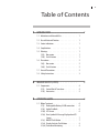
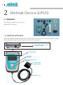
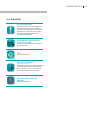
Instructions For Use PATIENT MANUAL BTT01-044-00 Rev1-01/2012 i BTT Melmak Development & Production GmbH Gewerbegebiet 16 82399 Raisting Germany Tel. +49 (0)8807 923922 Fax +49 (0)8807 8806 Email: [email protected] www.melmak.com MANUFACTURED FOR: Biomedical Tissue Technologies Pty Ltd (BTT) 342 Chisholm Road Auburn NSW 2144 Tel.: +61 2 8717 7940 Fax: +61 2 8717 7999 www.biottech.com (All enquiries regarding the Melmak device and support should be first directed to your local Melmak Distributor.) ii Symbols Manufacturer BTT Melmak Development & Production GmbH Gewerbegebiet 16, D-82399 Raisting, Germany Order Number 0483 The CE mark indicates conformity with European Council of directive concerning Medical Devices (93/42/EEC) Serial Number Keep dry Batch Number of the Product Follow Manual Type BF Protection Class II HF-Transmitter Non Sterile EU: Not for general Waste For details of how to dispose these items please contact your local waste agency or your local Melmak Distributor C-Tick Service Sticker Connector with Electrostatic discharge (ESD) – Attention: follow manual iii Table of Contents 1 INTRODUCTION... . .. . .. . .. . .. . .. . .. . .. . .. . .. . .. . .. . .. . .. . . . 1.1 Indications and Intended Use . . . . . . . . . . 1 1.2 Use with Internal Fixation . . . . . . . . . . . . 1 1.3 Contra-indications . . . . . . . . . . . . . . . 1 1.4 Complications . . . . . . . . . . . . . . . . . 1 1.5 Warnings . . . . . . . . . . . . . . . . . . . 1.5(i) Non-union . . . . . . . . . . . . . . . 1.5(ii) Fresh Fracture . . . . . . . . . . . . . 1 1 1 1.6 Precautions . . . . . . . . . . . . . . . . . . 1.6(i) Non-union . . . . . . . . . . . . . . . 1.6(ii) Fresh Fracture . . . . . . . . . . . . . 2 2 2 1.7 General Precautions . . . . . . . . . . . . . . 2 1.8 Safety Instructions . . . . . . . . . . . . . . . 3 2 MELMAK.DEVICE.(LIPUS) . ... ... ... ... ... ... ... ... ... .. . . 2.1 Components . . . . . . . . . . . . . . . . . . 2.1(i) Control Unit & Transducer . . . . . . . . 2.1(ii) Accessories . . . . . . . . . . . . . . . 4 4 4 5 3 OPERATING.GUIDE. ... ... ... ... ... ... ... ... ... ... ... ... .. . . 3.1 Before Treatment. . . . . . . . . . . . . . . . 3.1(i) Rechargeable Battery & USB connection. . 3.1(ii) Audio Feedback. . . . . . . . . . . . . 3.1(iii) LCD Screen . . . . . . . . . . . . . . . 3.1(iv) Error Symbols & Message Displayed on LCD Screen . . . . . . . . . . . . . . . . . 3.1(v) ON/OFF Push Button . . . . . . . . . . 3.1(vi) Display Statistics Push Button . . . . . . 3.1(vii) Transducer Monitoring . . . . . . . . . 1 6 6 6 6 7 7 8 8 6 iv INTRODUCTION 4 USE.INSTRUCTIONS .... .... .... .... .... .... .... .... .... .... .... .... .. . . 10 4.1 Non-Cast Use Instructions . . . . . . . . . . . . 10 4.2 Use Instructions When Using Strap Attachment Over Cast . . . . . . . . . . . . . . . . . . . 11 4.3 Use Instructions When Transducer Holder is Incorporated Into Cast . . . . . . . . . . . . . 12 5 CARE.AND.MAINTENANCE ... . .. . .. . .. . .. . .. . .. . .. . .. . . . 14 5.1 Care and Cleaning of the Melmak Device . . . . . 14 5.2 Disposal of Melmak Device . . . . . . . . . . . 15 5.3 Warranty and Statutory Rights . . . . . . . . . 15 5.4 Enquiries . . . . . . . . . . . . . . . . . . . 15 5.5 Servicing . . . . . . . . . . . . . . . . . . . 15 5.6 Melmak Service and Support Centres . . . . . . 15 5.6(i) European Authorised Representative . . . 15 5.6(ii) Australian Representative . . . . . . . . 15 6 TECHNICAL.INFORMATION... . .. . .. . .. . .. . .. . .. . .. . .. . . . 6.1 Control Unit Specification . . . . . . . . . . . . 16 6.2 Battery Charger Specification . . . . . . . . . . 16 6.3 Information about Electro-Magnetic-Compatibility (EMC) . . . . . . . . . . . . . . . . . . . . . 17 6.3(i) Guidelines and Manufacturer’s Declaration Electro-Magnetic Emission . . . . . . . 17 6.3(ii) Guidelines and Manufacturer’s Declaration Electro-Magnetic Stability . . . . . . . . 18 6.3(iii) Declaration Conformity . . . . . . . . . 21 16 INTRODUCTION 1 Introduction The Melmak Device is a Low Intensity Pulsed Ultrasound Device (LIPUS). LIPUS devices have been clinically found to support and accelerate the healing process of fresh fractures and non-unions. The Melmak Device is intended for non-invasive use only, and should only be used as prescribed by 1.4 Complications There have been no known adverse reactions or medical complications related to the use of the Melmak Device. Warnings a Physician or other Health Professional for its intended use. 1.5 Treatment is carried out for 20 minutes, once a day. Patients should treat themselves at approximately the same time each day. benefit, evidence of safety and effectiveness has not been established in the following: 1.1 Indications and Intended Use The Melmak Device is indicated for the treatment of fresh bone-fractures and established non-unions excluding treatment of the skull and the vertebral column. The location and type of fracture will influence results. This non-invasive treatment can only be prescribed by a Physician or other Health Professional. 1.2 Use with Internal Fixation The Melmak Device can be used in the presence of metal screws and plates. 1.3 Contra-indications There are no known Contra-indications to the use of the Melmak Device. Whilst use of the Melmak Device may be of clinical 1.5(i) Non-union ♦ For the treatment of fractures of the vertebrae or skull ♦ In the skeletally immature 1.5(ii) Fresh Fracture ♦ For the treatment of fractures of the vertebrae or skull ♦ All fracture types ♦ In the skeletally immature ♦ Reduced fractures which remain substantially displaced ♦ For pregnant and breast feeding women ♦ For use in pathological fractures due to bone pathology or malignancy ♦ For complex fractures requiring surgical intervention to reduce and stabilise 01 02 INTRODUCTION ♦ For use in patients with vascular disease or somatosensory dysfunction ♦ For use in patients with any neurological disorders which may affect the general wellbeing of the person, including any condition leading to nutritional deficiency ♦ For use in patients taking various medications including phosphonate therapy, steroids and cardiac medication ♦ If using for greater than the recommended 20 minutes per day ♦ For use outside the recommended clinical parameters, including prolonged use beyond prescribed guidelines 1.6 Precautions Whilst use of the Melmak Device may be of clinical benefit, evidence of safety and effectiveness has not been established in the following: 1.6(i) Non-Union ♦ Reduced fractures which remain substantially displaced. The Melmak Device will not correct any displacement. ♦ For pregnant and breast feeding women ♦ For complex fractures requiring surgical intervention to reduce and stabilise 1.6(ii) Fresh Fracture ♦ Reduced fractures which remain substantially displaced. The Melmak Device will not correct any displacement. ♦ For pregnant and breast feeding women ♦ For complex fractures requiring surgical intervention to reduce and stabilise ♦ If using for greater than the recommended 20 minutes per day ♦ For use outside the recommended clinical parameters, including prolonged use beyond prescribed guidelines 1.7 General Precautions Mobile phones may cause interference. Please keep mobile phones at a safe distance from the Melmak Device during a treatment. The Melmak Device is a medical electrical device and needs special precautions regarding electromagnetic compatibility (EMC) and must be installed according to EMC information. People with cardiac pacemakers should get clearance from their physician prior to use. Some individuals may be susceptible to the following: ♦ a potential allergic reaction to the coupling gel ♦ If using for greater than the recommended ♦ mild swelling ♦ For use outside the recommended clinical ♦ pain 20 minutes per day parameters, including prolonged use beyond prescribed guidelines ♦ muscle spasm at treatment site ♦ mild erythema INTRODUCTION If any of these occur the individual should cease use of the Melmak Device and seek medical attention immediately. 1.8 Safety Instructions The Melmak Device is intended for non-invasive use only, and should only be used as prescribed by a Physician or other Health Professional for it’s intended use. The Operating Guide must be followed accurately. The Melmak Device is to be used only with Melmak specified and supplied equipment and not in combination with other devices. For external use only. The Melmak Device is to be operated and stored under dry conditions. For any queries please contact your local Melmak Distributor. 02 04 INTRODUCTION 2 2.1 Melmak Device (LIPUS) Components The following components are part of your Melmak Device shipment. 2.1(i) Control Unit and Transducer Tested and validated for 1500 treatments. This model Transducer transmits a low intensity, high frequency pulsed ultrasound signal through the patient’s skin to the fracture site to be treated. MINI USB CONNECTOR for battery charging LCD SCREEN ON / OFF Push button DISPLAY STATISTICS Push button ULTRASOUND TRANSDUCER LENGTH 1.5m MELMAK DEVICE 2.1(ii) Accessories ULTRASOUND GEL 250 gram bottle. Gel must be applied to Transducer head prior to all treatment to enable ultrasound signal to pass from Transducer through skin to the fracture site. Only use Gel supplied by your local Melmak Distributor. ASSEMBLED TRANSDUCER HOLDER & STRAP Used to position ultrasound Transducer over fracture site FELT For cast application BATTERY CHARGER (including adaptors) USB Cable is used for charging the internal non-replaceable battery of the Melmak Device. Length 1.8m. For international use multiple adaptors are supplied. INSTRUCTIONS FOR USE MANUAL Operation instructions 05 INTRODUCTION 06 3 3.1 Operating Guide Millennium Electronics Pty. Ltd. Before a Treatment The Melmak Device is a battery operated 4. 2100-0148 23 July FUNCTIONAL SPECIFICATION the charging process, thewhich Melmak Device The ECU features aDuring backlit Liquid Crystal Display (LCD) provides the patient with information on the remaining treatment time, number of treatments left to be completed. In cannot be operated. addition, the ECU has two (2) tactile push buttons that enables the patient to start and stop the treatment device, it and to display the status of the treatment. In summary, the ECU provides the following features: will need to be charged prior to use using a country 3.1(ii) Audio Feedback Liquid Crystal Display (LCD) with green backlight specific adaptor. On/Off Push Button A high frequency audible sound is generated to give Display Statistics Button 3.1(i) Rechargeable Battery and USB connection Rechargeable Lithium-Ion Battery feedback when: Audio Feedback USB Connection for charging connection to a Personal Computer (PC) for set up ♦ Pressing anyand button and data logging. If gelDisplay is required, 3 short beeps, repeated 4.1. The Melmak Device Control Unit is powered by a Liquid♦Crystal approximately every 3 seconds non-replaceable, rechargeable Lithium-Ion (Li-On) The Liquid Crystal Display (LCD) has the following specification: (Wthe x H): 63.2 mm x38.5 battery pack. A medical grade battery charger with Display♦sizeAt completion of mm a treatment, alarm will sound Viewing area size (W x H): 59.9 mm x 30.5 mm inbuilt USB connector is used to charge the internal 6 short beeps Driving Condition : 1/3 Duty (i.e. 3 Back Planes) , 1/3 Bias, 3V Operate, battery. Country specific adaptor must be used. LCD Type : TN Type ♦ Low battery level is detected The USB mini connector on the top edge of the Melmak Device is used for charging. Viewing Angle: 6 O'clock Polarizer Type & Mode: Transflective Connector Type : Pins 3.1(iii) Operating Temp: 10°C ~ 50°C Storage Temp : 0°C – 65°C LCD Screen All functions of the Melmak Device will be disabled The design of the LCD is as follows: Treatment time remaining in minutes and seconds. Maximum time 20:00. if the device is not charged. The voltage level of the battery pack is constantly monitored by the Control Unit while operating and the voltage level is displayed on the LCD. Millennium Electronics Pty. Ltd. Millennium Electronics Pty. Ltd. 2100-0148-01C 23 July 2010 When the battery voltage falls below 3.55 Volt during a treatment cycle, in addition to the flashing “ 2100-0148-01C ” symbol at 1 Hertz, i.e. 500 ms on and 500 ms off, the LCD will also 2010 show “Lo Bat”23asJuly follows: When the battery voltage falls below the critical battery level during a treatment session, in addition ” signal. to flashing, the LCD will also show “ When the “ ” signal is present, the current When the battery voltage falls below 3.55 Volt during a treatment cycle, in addition to the flashing “ ” symbol at 1 Hertz, i.e. 500 ms on and 500 ms off, the LCD will also show “Lo Bat” as follows: Formatted: English (U.S.), Do not check spelling or grammar Formatted: English (U.S.), Do not check spelling or grammar Formatted: English (U.S.), Do not check spelling or grammar Formatted: English (U.S.), Do not check spelling or grammar Figure 16 – Example of the display on LCD when low battery level is detected. Once the treatment is completed, the ECU will not allow further treatment to commence until the battery is recharged. Pressing and releasing the ON/OFF Push Button when the battery voltage is below 3.55 Volt cannot initiate a new treatment cycle. The LCD will light and display the following for 5 seconds and then switch off. Once the treatment is completed, the ECU will not allow further treatment to commence until the battery is recharged. Pressing and releasing the ON/OFF Push Button when the battery voltage is below 3.55 Volt cannot initiate a new treatment cycle. The LCD will light and display the following for 5 seconds and then switch off. treatment will be completed but further treatments will not be possible until the Melmak Device is recharged. Figure 16 – Example of the display on LCD when low battery level is detected. Formatted: English (U.S.), Do not check spelling or grammar Formatted: English (U.S.), Do not check spelling or grammar Battery Number of Total Number Figure 2 - BTT Unit Display showing all available segments status treatments of available indicator completed treatments During the charging process, the LCD will show the letter “P” and the animated battery symbol Copyright Millennium Electronics Pty. Ltd Figure 1: Display showing all symbols will be displayed. Figure 17 – Example of the display on LCD when low battery level is detected at the start of the treatment cycle 4.6. Add gel indicator Audio Feedback Figure 17 – Example of the display on LCD when low battery level is detected at the start of the treatment cycle A high frequency audible sound is generated (1.7kHz approx.), to give an audible 4.6. Audio Feedback feedback for the following operations: Pressing any button will sound for 200mS approximately. A high frequency audible sound is generated (1.7kHz approx.), to give an Ifaudible gel is required, an audible alarm will also be sounded, 3 short beeps, repeated feedback for the following operations: approximately every 3 seconds. 4.7. Pressing any button will sound for 200mS approximately. If gel is required, an audible alarm will also be sounded, 3 short beeps, repeated Low battery level is detected. approximately every 3 seconds. At the completion of a treatment the audible alarm will also sound 6 short beeps. At the completion of a treatment the audible alarm will also sound4.7. 6 short USB beeps.and External Battery Charger Connector Low battery level is detected. USB and External Battery Charger Connector The USB mini connector on the top edge of the BTT unit, is used for communications to a PC, and for charging the internal Lithium Ion battery. A Power Pack with inbuilt USB mini B connector can be used to charge the internal battery. The USB mini connector on the top edge of the BTT unit, is used for communications to a PC, and for charging the internal Lithium Ion battery. Millennium A Power Pack with inbuilt USB mini B connector can be used toCopyright charge the internal Electronics Pty. Ltd battery. Page 14 of 16 Page 7 of OPERATING GUIDE 3.1(iv) Error Symbols and Message Displayed on LCD Screen “ The Control Unit monitors the Transducer status and gel level continuously during the 20 minute treatment cycle. The treatment will be interrupted if an error mode occurs. In this case the error message will be 07 ”. This message will be displayed for 1 minute and then the device will switch off. If an error message is displayed please contact your local Melmak Distributor. ♦ NO ALLOCATED TREATMENTS REMAINING “ ” Once all treatments allocated to the Control displayed as follows: Unit are used the following error message will be ♦ INSUFFICIENT GEL “ ” If insufficient gel is detected before or during a treatment cycle, the Control Unit will suspend the displayed “ ”. If above error is displayed please contact your local Melmak Distributor. treatment cycle unit until sufficient gel is applied. 3.1(v) ON/OFF Push Button The Control Unit will generate three audible beeps The ON/OFF Push Button on the Control Unit every 3 seconds and will display a flashing drop Millennium Electronics 2 allowsPty. theLtd.patient to start and terminate a treatment symbol “ ” in the lower right corner of the display. cycle. If sufficient gel is not applied within 2 minutes The information provided by the LCD includes: after error symbol is displayed the device will Remaining time of the 20 minutes treatment cycle in minutes and seconds STARTING A TREATMENT SESSION The number of programmed treatments and completed treatments, e.g. 34/150 automatically switch off. (Gellevel mustand becharge placedstatus on theindicator ultrasound head to enable Battery “Add Gel” symbolof ultrasound signal from the ultrasound ♦ LOW BATTERY “ ” transmission Once the Control Unit detects a low battery level Transducer 4.2. ON/OFF Push across Buttonthe skin to the fracture site) this will be displayed with the following message: The ON/OFF Push Button on the ECU allows the patient to start and terminate ♦ Pressing and releasing the ON/OFF Push “ ” and the flashing battery symbol “ treatment ” cycle. Button an willaudible start abeep 20 minute treatment session. and switch on the LCD backlight for 5 seco displayed in the lower left corner of the display,The ECU will generate when the ON/OFF Push ButtonUnit is pressed. The Control will generate a short beep indicating battery needs to be charged. The low and athe LCD will be lit for 5 seconds. The 4.2.1. Starting Treatment Cycle battery status allows you to finish the current If the treatmentminute cycle has not been started, and releasing the ON/OFF P count down timerpressing will commence treatment but will not allow for further treatmentsButton will20start the treatment cycle. The ECU will generate a short beep counting the push down. button is pressed and the LCD and its backlight will be lit f to be performed until the battery is recharged. acknowledge Millennium Electronics Pty. Ltd. 2100-0148-01C 23 July 2010 When the battery voltage falls below 3.55 Volt during a treatment cycle, in addition to the flashing “ ” symbol at 1 Hertz, i.e. 500 ms on and 500 ms off, the LCD will also show “Lo Bat” as follows: Formatted: English (U.S.), Do not check spelling or grammar Formatted: English (U.S.), Do not check spelling or grammar lennium Electronics Pty. Ltd. 2100-0148-01C 23 July 2010 When the battery voltage falls below 3.55 Volt during a treatment cycle, in addition to the flashing “ ” symbol at 1 Hertz, i.e. 500 ms on and 500 ms off, the LCD will also show “Lo Bat” as follows: Formatted: English (U.S.), Do not check spelling or grammar Formatted: English Do Figure 16 – Example of the display on LCD when(U.S.), low battery level is detected. not check spelling or grammar Once the treatment is completed, the ECU will not allow further treatment to commence until the battery is recharged. Pressing and releasing the ON/OFF Push Button when the battery voltage is below 3.55 Volt cannot initiate a new treatment cycle. The LCD will light and display the following for 5 seconds and then switch off. Formatted: English (U.S.), Do not check spelling or grammar Figure 16 – Example of the display on LCD when low battery level is detected. Once the treatment is completed, the ECU will not allow further treatment to commence until the battery is recharged. Pressing and releasing the ON/OFF Push Button when the battery voltage is below 3.55 Volt cannot initiate a new treatment cycle. The LCD will light and display the following for 5 seconds and then switch off. Formatted: English (U.S.), Do Figure 17 – Example of the display on LCD when low battery level is detected at the start of the treatment cycle not check spelling or grammar 4.6. Audio Feedback A high frequency audible sound is generated (1.7kHz approx.), to give an audible feedback for the following operations: Pressing any button will sound for 200mS approximately. If gel is required, an audible alarm will also be sounded, 3 short beeps, repeated approximately every 3 seconds. At the completion of a treatment the audible alarm will also sound 6 short beeps. Figure 17 – Example of the display on LCD when low battery level is detected at the start of the treatment cycle Low battery level is detected. 4.6. Audio Feedback Pressing and releasing the ON/OFF button will light the display for 5 seconds and then switch off the device. 4.7. seconds as illustrated in Figure 3 USB and External Battery Charger Connector A high frequency audible sound is generated (1.7kHz give an on audible Theapprox.), USB minitoconnector the top edge of the BTT unit, is used for communications to feedback for the following operations: a PC, and for charging the internal Lithium Ion battery. Pressing any button will sound for 200mS approximately. A Power Pack with inbuilt USB mini B connector can be used to charge the internal battery. If gel is required, an audible alarm will also be sounded, 3 short beeps, repeated approximately every 3 seconds. Millennium Electronics Pty. Ltd At the completion of a treatment the audibleCopyright alarm will also sound 6 short beeps. Low battery level is detected. 4.7. Page 14 of 16 USB and External Battery Charger Connector ♦ TRANSDUCER FAULT “ ” If the Control Unit detects a Transducer fault, the treatment cycle will be interrupted until the Transducer fault is rectified. The following error message will be displayed: The USB mini connector on the top edge of the BTT unit, is used for communications to a PC, and for charging the internal Lithium Ion battery. A Power Pack with inbuilt USB mini B connector can be used to charge the internal battery. pyright Millennium Electronics Pty. Ltd Page 14 of 16 Figure 3 – Example of display on the LCD at the start of a treatment cycle Figure 2: Example of display on the LCD at the start of a treatment session The ECU will commence the treatment cycle and the 20 minute treatment count do timer will commence counting. An example of the information being displayed on LCD 5 seconds into the 20 minutes treatment cycle is as follows: 23 July 2010 Formatted: Complex Script Font: 11 pt, English (U.S.), Do not check spelling or grammar 08 INTRODUCTION END OF A TREATMENT SESSION and the total number of programmed treatments Figure 10 – Example of display on LCD when the Display Statistics Push B pressed Figure 5 – Example of display on LCD showing 7 minutes and 10 isseconds 150. and released once. remaining thecountdown treatment cycle ♦ Whenonthe timer reaches zero, the treatment is completed 4.2.3. End of a Treatment Cycle and a short audible beep When the 20 treatment count will down timer zero, the treatment is willminutes be heard. The LCD show thereaches following completed and the ECU will generate a short audible beep and the LCD will show the for 20 seconds and then switch off. following for 20 seconds and then switch off. Formatted: English (U.S.), Do not check spelling or grammar Figure 11 – Example of theondisplay thethe LCD when the Display Figure 4: Example of the display the LCDon when Display Statistics Push Statistic Button pressed released second timethe while the backlight Button isispressed andand released second time while backlight is enabled is enabled. 3.1(vii) 3: ExampleofofLCD LCD atatthe of of a 20the minute treatment FigureFigure 6 – Example theend end 20 minutes treatment cycle Transducer Monitoring The Control Unit will monitor the Transducer status 4.2.4. Terminating a Treatment Cycle gela level continuously throughout the 20 minutes PressingTERMINATING and holding the ON/OFF Push Button for 4 seconds or longer and during A TREATMENT treatment cycle, the ECU will stop and terminate the treatment cycle. treatment session. If the treatment cycle and has gone over the sixteen (16) minutes the 20 minutes treatment ♦ Pressing holding ON/OFF PushofButton cycle, the ECU will registered the treatment cycle as a valid cycle and the LCD will TRANSDUCER FAULT forFigure 4 seconds longer a treatment stop4.2.3 above, display as in 7. Theor ECU will during behave as outlined in will Section i.e. Figure 12 – Example of the display on the LCD five (5) seconds after the D the ECU will generate a short audible beep and the display will continue to show the treatment session. Button is pressed and released the second time. ♦Statistics If the Push Control Unit detects a Transducer fault, “End” for 20 seconds and then switch off. ♦ The Control Unit will generate a short audible 4.4. Formatted: English (U.S.), Do Transducer Monitoring the Control Unit suspend the treatment not checkwill spelling or grammar the Transducer fault rectified. The througho beep and the display will continue to show “End” The ECU will session monitor until the Transducer status and GelisLevel continuously 20 minutes treatment cycle. Melmak Device may need to be returned to your for 20 seconds and then switch off. The following local table Melmak tabulates the conditionsfor in which the ECU the sta Distributor diagnostic testsdetermines and the Transducer and Gel level potential repair. 3.1(vi) Display Statistics Push Button Gel Sense Voltage Condition Notes ♦ Voltage The LCD will display following signal Error Condition Gel Sense ≤ 500mV Short errorCircuited The Display Statistics Push Button is only operational Sensor “ when a treatment is in progress. The Statistics-button enables the patient to: ght Millennium Electronics Pty. Ltd ♦ Pressing and releasing the ON/OFF Push Button Copyright Millennium Electronics Ltd Control will switch Pty. of the Page 9 of 16 ♦ Switch on the back light by pushing and releasing the button once ♦ Receive information about the number of ” for 1 minute and then switch off. treatments completed and the programmed number of treatments by pushing and releasing the button a second time. This will be displayed by the following message in the lower right corner of the display , indicating 34 completed treatments Unit immediately. INSUFFICIENT GEL ♦ If insufficient gel is detected during the treatment cycle, the Control Unit will suspend the treatment until sufficient gel is applied to Transducer head. ♦ The Control Unit will generate 3 audible beeps every 3 seconds and will display a flashing “ ” symbol. Figure 13 – Example of the display on LCD when a Transducer fault is detected. Pressing and releasing the ON/OFF Push Button will switch off the ECU immediately. 4.4.2. Insufficient Gel If insufficient gel is detected during the treatment cycle, the ECU will suspend the treatment cycle until sufficient gel is applied. The ECU will generate three (3) audible beeps every 3 seconds and will display the “ ” symbol will flash at 1 Hertz, i.e. 500ms on and 500 ms off: OPERATING GUIDE Formatted: Complex Script Font: 11 pt, English (U.S.), Do not check spelling or grammar Formatted: Complex Script Font: 11 pt, English (U.S.), Do not check spelling or grammar Figure 5: of theofdisplay on LCD when insufficient gel is detectedgel is detected Figure 14Example – Example the display on LCD when insufficient The ECU will apply the gel sensing signal for 2 minute at a rate of 100 ms every ♦ The Unitgelwill apply the gel sensing 500ms and if theControl insufficient condition persists at the endsignal of the 2 minutes time period, the ECU will reset the 20 minutes treatment cycle timer and will not register for 2 minutes. If the insufficient gel condition the treatment as a valid treatment. persists at the end of the 2 minute time period, the Unit right MillenniumControl Electronics Pty. will Ltd reset the 20 minute treatment session timer and will not register the treatment as a valid treatment. ♦ If the insufficient gel condition is not rectified for another minute, i.e. 3 minutes after the low gel condition is detected, the Control Unit will switch off. ♦ Pressing and releasing the ON/OFF Push Button or the Display Statistics Push Button has no effect while “ ” is being displayed. Page 12 of 16 09 10 INTRODUCTION 4 4.1 Use Instructions Non-Cast Use Instructions 1. Before starting, Physician will mark an “X” over fracture site, to ensure accurate placement of Transducer holder for every treatment. You will 4. Hold Transducer and place a small amount of ultrasound gel on the Transducer face, approximately 1.5cm diameter. need to ensure this point is reproducible for each treatment. An indelible marker may assist. Place ultrasound Transducer through Transducer holder. Ensure cable is routed through cut out on cap and secure by closing cap. 2. Place strap with Transducer holder over fracture site and stabilise securely using the Hook and Loop fasteners. It is vital that Transducer holder be held securely over site to be treated, to ensure Transducer is accurately positioned. 3. Open Transducer holder by pushing two turquoise tabs on either side of Transducer holder towards centre. The spring mechanism on the cap provides light pressure to the Transducer. It ensures good contact to the gel and skin over the treatment area for ultrasound transmission. USE INSTRUCTIONS 5. Press ON/OFF button to start treatment. Timer will illuminate and count down from 20 minutes and then turn off automatically. 3. Hold Transducer and place a small amount AFTER TREATMENT HAS COMPLETED of Transducer gel on the Transducer face. Approximately 1.5cm diameter. 6. Undo strap and remove Transducer head from treatment site. Clean gel from Transducer head, strap and skin with soft cloth. Pack Melmak device into carry case for safe keeping. 4.2 Use Instructions When Using Strap Attachment Over Cast 1. Strap with Transducer holder to be secured over your fracture site and stabilised securely using the Hook and Loop fasteners. 2. Open Transducer holder by pushing two turquoise tabs on either side of Transducer holder towards centre. 4. Position the Transducer in the window of the cast directly over the fracture site. Ultrasound gel must be touching the skin. Close cap to secure. 11 12 INTRODUCTION 5. Press ON/OFF button once to begin treatment. 2. Hold Transducer and place a small amount 6. Remove Transducer head from treatment site. 3. Place ultrasound Transducer through Timer will illuminate and count down from 20 minutes and then turn off automatically. Clean gel from Transducer head, strap and skin with a soft cloth. 7. Place the round felt plug into the cast window and close cap to secure. 4.3 of Transducer gel on the Transducer face. Approximately 1.5cm diameter. Transducer holder. Ensure cable is routed through cut out on cap and secure by closing cap. Ultrasound gel must be touching the skin. Close cap to secure. Use Instructions When Transducer Holder is Incorporated into Cast 1. Open Transducer holder by pushing two turquoise tabs on either side of Transducer holder towards centre. 4. Press ON/OFF button once to begin treatment. Timer will illuminate and count down from 20 minutes and then turn off automatically. USE INSTRUCTIONS 5. Remove Transducer head from treatment site. Clean gel from Transducer head, strap and skin with a soft cloth. 6. Place the round felt plug into the cast window and close cap to secure. 13 14 INTRODUCTION 5 5.1 Care and Maintenance Care and Cleaning of the Melmak Device The Melmak Device must be used according to the following instructions: ♦ The Melmak Device is only to be used according to the intended use mentioned in this manual. ♦ Please read this manual very carefully and only operate and handle the Melmak Device according to these instructions. ♦ The Melmak Device must only be used with Melmak supplied and specified equipment. The Melmak Device must not be used in combination with other devices. Warning: Using other than Melmak specified cables and accessories may negatively affect electromagnetic compatibility performance. ♦ Never use cleaning agents or solvents to clean device, its components or accessories. For cleaning use only a soft moist cloth or soft paper towel or tissue. ♦ The Melmak Device must be operated under dry conditions. The Melmak Control unit must never be exposed to liquid. ♦ Please check the Melmak Device and its components after each treatment for any damage. Never use a damaged or broken device or component. In case of damage contact your local Melmak Distributor. ♦ Do not open and do not try to repair or modify the Melmak Device. ♦ Warning: Do not touch Connector pins marked ”. Connections with the following symbol “ between these pins must not be conducted without using specified Electrostatic Discharge (ESD) Safety precautions. -> Using procedures to avoid electrostatic charging (e.g. conducting flooring, non-synthetic clothing) -> Discharging of the own body to ground or large metallic items -> Connection to ground by wristband ♦ Warning: The Melmak Device is not to be stored or located close to other electrical equipment. ♦ Use only the charger and the accessories supplied by your local Melmak Distributor to avoid any increase in emissions or interference resistance by the Melmak device. ♦ All staff including e.g. medical engineers and nursing staff are recommended to receive explanation and training in ESD procedures. ♦ The minimum specifications of ESD precautionary procedure training are: -> Introduction into physical basics of electrical charging and the danger of destroying electrical functionality of devices. -> Methods to avoid electrical charging and explanation for necessity of grounding. ♦ Please contact your local Melmak Distributor in case of any questions or concerns. CARE AND MAINTENANCE 5.2 Disposal of Melmak Device Disposal of electrical waste is an important environmental issue. Disposal of this device should not be treated like household waste. Please contact your local Melmak Distributor for On the rear of the Melmak Control Unit you find the following service sticker “ mandatory date for next service. 5.6 ” indicating the Melmak Service and Support Centres information on correct disposal of your Melmak Device. 5.6(i) To minimise environmental impact, components of BTT MELMAK DEVELOPMENT & this device will be recycled where possible. 5.3 Warranty and Statutory Rights The Melmak product is covered by a 2 year limited warranty. Please contact your local Melmak Distributor for full warranty terms. In addition, the Melmak product may be covered by specific statutory rights in your jurisdiction. To find out details of any statutory rights you may have (for e.g. under any consumer guarantees) please contact your local Melmak Distributor. Do not try to repair or modify your Melmak Device. This will void your warranty. 5.4 Enquiries For any questions, concerns or assistance please contact your local Melmak Distributor. 5.5 Servicing Return your Melmak Device to your local Melmak Distributor for a technical service once a year in order to ensure optimum performance of the device and the intended therapeutic response. European Authorised Representative PRODUCTION GMBH Gewerbegebiet 16 82399 Raisting Germany Phone: +49 (0)8807/ 92 39 22 Fax: +49 (0)8807/ 88 06 www.melmak.com 5.6(ii) Australian Representative BIOMEDICAL TISSUE TECHNOLOGY PTY LTD (BTT) 342 Chisholm Road Auburn NSW 2144 Phone: +61 (0)2 8717 7940 Fax: +61 (0)2 8717 7999 www.biotech.com 15 16 INTRODUCTION 6 6.1 Technical Information Control Unit Specification 6.2 Battery Charger Specification ♦ Ultrasound Frequency f: 1.5 + 5% MHz ♦ Input Voltage: 100 - 240 VAC ♦ Modulating Burst Width tp: 200 + 10% μs ♦ Input Current: <0.5 A RMS Max ♦ Repetition Rate REF: 1.0 + 10% KHz ♦ Input Frequency: 47 - 63 Hz ♦ Acoustic Power P1: 116mW ♦ Output Voltage: 5.0 V, No Load to Full Load, ♦ Spatial Average - Temporal Average (SATA) Ie: 30 + 30% mW/cm 2 ♦ Spatial Average - Temporal Maximum (SATM) Im: 116 + 30% mW/cm2 ♦ Power Supply - Lithium Ion Rechargeable Battery: 3.7 DCV nominal ♦ Power Input Pin: 1.1 + 0.6 W ♦ Beam Non-Uniform Ratio RBN: <6 ♦ Waveform: Pulsed ♦ Effective Acoustic Radiating Area Aer: 3.88cm2 ♦ Duty Factor DF: 5 ♦ Time Average Intensity: 6 ♦ Weight (Control Unit including Transducer): approximately 285 g No Minimum Load Required ♦ Output Current: 1.0 A ♦ Output Power (Rated): 5 W Max TECHNICAL INFORMATION 6.3 Information about Electro-Magnetic-Compatibility (EMC) 6.3(i) Guidelines and Manufacturer’s Declaration - Electro-Magnetic Emission The Melmak Device is destined for the use under the circumstances listed below. The customer and the user of the Melmak device may ensure that the device will be operated in such a surrounding. Transient emissions measuring Correlations HF emission according to CISPR 11 Group 1 HF emission according to CISPR 11 Class B Emission of harmonic according to IEC 61000-3-2 Class A Emission of voltage variation / Flicker according to IEC 61000-3-3 Agreed Electro-Magnetic Environment – Guideline The Melmak Device applies HF-Energy for internal function only. Therefore the HFEmission is very low and it’s unlikely, that it will interfere with other electronic devices nearby. The Melmak Device is a Device which is for the use in every facility including residential areas and those connected to the public power supply, supplying buildings made for living. 17 18 INTRODUCTION 6.3(ii) Guidelines and Manufacturer’s Declaration - Electro-Magnetic Stability The Melmak device is destined for the use under the circumstances listed below. The customer and the user of the Melmak device may ensure, that the device will be operated in such a surrounding. Stability Tests IEC 60601-Test Level Correlations Level Electro-Magnetic Environment - Guidelines + 6 kV Contact discharge + 6 kV Contact discharge Floors may consist of wood or concrete or ceramic tile. If the + 8 kV Air discharge + 8 kV Air discharge floor consists of synthetic material, the relative humidity has to be at least 30%. + 2 kV for power line + 2 kV for power line The quality of the supply voltage Fast transients / Bursts should be up to the standard of according to IEC 61000-4-4 + 1 kV for input- and + 1 kV for input- and a typical business- or hospitaloutput-lines (not applicable) output-lines (not applicable) environment. Discharge static electricity (ESD) according to IEC 61000-4-2 + 1 kV push-pull voltage Surge Voltages (Surges) according to IEC 61000-4-5 + 2 kV common-mode voltage (not applicable) Voltage drops, short time < 5% U T interruption and variations of (> 95% voltage drop of UT) for ½ of Period supply voltage according to IEC 61000-4-11 40% U T (60% voltage drop of UT) for 5 Periods + 1 kV push-pull voltage + 2 kV common-mode voltage (not applicable) < 5% U T (> 95% voltage drop of UT) for ½ of Period 40% U T (60% voltage drop of UT) for 5 Periods 70% U T 70% U T for 25 Periods for 25 Periods (30% voltage drop of UT) (30% voltage drop of UT) < 5% U T < 5% U T for 5 s for 5 s (> 95% voltage drop of UT) Magnetic Field at supply 3 A/m frequency (50/60 Hz) according to IEC 61000-4-8 Note: U T = alternating voltage before application of test levels The quality of the supply voltage should be up to the standard of a typical business- or hospitalenvironment. The quality of the supply voltage should be up to the standard of a typical business- or hospitalenvironment. If the user of the Melmak Device requires continuous function even at interruptions of the power supply, it’s recommended to operate the Melmak Device with an independent power supply or a battery. (> 95% voltage drop of UT) 3 A/m Magnetic fields of the supply frequency should be up to the standard of a typical businessor hospital-environment. TECHNICAL INFORMATION 6.3(ii) Guidelines and Manufacturer’s Declaration - Electro-Magnetic Stability (continued) The Melmak device is destined for the use under the circumstances listed below. The customer and the user of the Melmak device may ensure, that the device will be operated in such a surrounding. Stability Tests IEC 60601-Test Level Correlations Level Electro-Magnetic Environment - Guidelines Portable and mobile walkie-talkies may not be operated in a lower distance to the Ultrasound-Therapy device, including the wires, than according to the recommended security distance, determined by the following equation: Recommended Security Distance: conducted HF-transient 3 Veff according to IEC 61000-4-6 150 kHz to 80 MHz 3 Veff d = 1,16 * P 3 V/m radiated HF- transient according to IEC 61000-4-3 80 MHz to 2,5 GHz 3 V/m d = 1,16 * P for 80 MHz to 800 MHz d = 2,33 * P for 800 MHz to 2,5 GHz P = actual power output of sender (S) expressed as in Watt (W) according to the information of the sender manufacturer d = recommended security distance expressed as in Meter (m) The field intensity of static transmitter may be for all frequencies according to an investigation on sitea lower than the correlations levelb. In the vicinity of device labelled with the following sign, interferences are possible. Note 1 Note 2 a b At frequencies of 80 MHz and 800 MHz the higher frequency range is valid These guidelines may not be applicable in all cases. The electromagnetic parameter propagation will be influenced by absorption and reflection of buildings, subjects or people. The wave band of static senders, e.g. the base station of a Mobile Telephone and mobile walkie-talkies, amateur radio operation devices, AM- and FM- Radio- and TV-Stations can in theory not be determined in advance. In order to investigate the electro-magnetic environment concerning static senders, a survey of the site has to be considered. If the determined field intensity on site, where the Melmak device will be operated, exceeds the above mentioned correlations level, the Melmak device has to be monitored, in order to verify the designated function. If unusual characteristics will be determined, additional action may be required, e.g. a different orientation or a different location of the Melmak device. For frequency range from 150kHz to 80MHz the field intensity may be lower than 10V/m. 19 20 INTRODUCTION 6.3(ii) Guidelines and Manufacturer’s Declaration - Electro-Magnetic Stability (continued) The Melmak device is destined for the use in an electro-magnetic environment, where the HF-transient is controlled. The customer or user of the Melmak device can help to avoid electro-magnetic inferences by keeping the minimum distance (see below) between portable and mobile HF-Telecommunication Devices (Senders) and the Melmak device – dependent on the output power of the communication device: Actual Power Output of Sender (W) Security Distance dependent on Transmitter Frequency (m) 150 kHz to 80 MHz d = 1,16 * P 80 MHz to 800 MHz d = 1,16 * P 800 MHz to 2,5 GHz d = 2,33 * P 0,01 0,116 0,116 0,23 0,1 0,366 0,366 0,73 1 1,16 1,16 2,33 10 3,66 3,66 7,36 100 11,6 11,6 23,3 For transmitter, who’s actual power output is not mentioned in the chart above, the recommended security distance d (m) can be determined by using the equation belonging to the corresponding column. P = actual power output of sender (S) expressed as in Watt (W) according to the information of the sender manufacturer. Note 1 Note 2 At frequencies of 80 MHz and 800 MHz the higher frequency range is valid These guidelines may not be applicable in all cases. The electromagnetic parameter propagation will be influenced by absorption and reflection of buildings, subjects or people. TECHNICAL INFORMATION 6.3(iii) Declaration of Conformity 21 If you have further questions or require additional information, please contact your local Melmak Distributor: Local Distributor Label Here