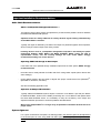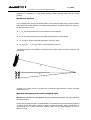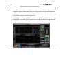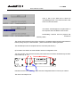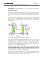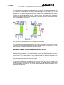
1
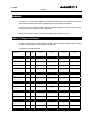
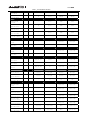
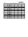
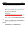
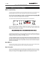
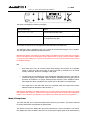
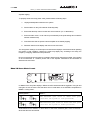
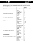
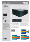
Update to NX241 Manual
LOAD2_15
NX241 New Setups
NX241 New Functions
NX Windows Loader
Application Notes
PAGE 2/24
WARNING :
TABLE OF CONTENTS
WARNING :
3
LOAD 2_15 SUPPORTED SETUPS
3
LOAD2_15 : NEW & IMPROVED NX241 SETUPS
6
GEO T SERIES & CD18
GEO S
PS15 ACTIVE
6
6
6
LOAD 2_15 : NX241 NEW FUNCTIONS & MENUS
7
MENU 1.1, INPUT METERING
MUTE, MENU 1.4
MENU 2.6 AMP GAIN
MENU 2.7 AMP POWER
MENU 2.8 SENSE ALERTS & RESET
DUPLICATION OF THE SUB OUTPUT ON PASSIVE SETUPS
DUPLICATION OF THE MAIN OUTPUT ON GEO-S PASSIVE WITH CARDIOID SUB SETUPS
INPUT PATCH, MENU3.2
7
7
7
8
9
10
10
10
IMPORTANT INSTALLATION RECOMMANDATIONS
11
AUDIO CHAIN RECOMMENDATIONS
SYSTEM ALIGNMENT
11
11
APPLICATION NOTE : DRIVING THE SUB FROM THE AUX SEND
14
NEXO WINDOWS LOADER
16
WARNING
INSTRUCTIONS
16
16
APPLICATION NOTE : RECOMMENDED INSTALLATION PRACTICES
19
PURPOSE OF THE RECOMMENDED INSTALLATION PRACTICES
SUGGESTED INSTALLATION RULES
RATIONALE ON INTERCONNECTION RULES
REFERENCES
19
19
22
23
ANNEX: QUICK MENU HELP
24
PAGE 3/24
WARNING :
WARNING :
In LOAD2_13, we have been obliged to re-organize the DSP memory of the NX241 and we have
had to erase some information that is normally kept when you update your firmware.
As a result, once the software update is finished you will be prompted to verify the value of the amp
power and amp gain in menus 2.6 & 2.7 respectively.
Please note the values in these menus before updating the software in your unit.
LOAD 2_15 Supported Setups
In order to change from one cabinet family to another, hold the A & B buttons down when resetting
the NX241. (Refer to page 10 of the NX241 User Manual)
47 setups are currently supported.
Setup Name
New
Mod.
CH 1
CH 2
CH 3
CH 4
ˇ
CD18 # 1 back
CD18 # 1 front
CD18 # 2 back
CD18 # 2 front
ˇ
CD18 # 1 back
CD18 # 1 front
CD18 # 2 back
CD18 # 2 front
ˇ
CD18 # 1 back
CD18 # 1 front
CD18 # 2 back
CD18 # 2 front
ˇ
CD18 # 1 back
CD18 # 1 front
CD18 # 2 back
CD18 # 2 front
CD12 # 1 back
CD12 # 1 front
CD12 # 2 back
CD12 # 2 front
CD12 # 1 back
CD12 # 1 front
CD12 # 2 back
CD12 # 2 front
S2 # 1
S2 # 2
S2 # 3
S2 # 4
S2 # 1
S2 # 2
S2 # 3
S2 # 4
B1-18 Left
B1-18 Right
AEM Left
AEM Right
B1-18 Left
B1-18 Right
AEM Left
AEM Right
S2
B1-18
AEM
-
S2
B1-18
AEM
-
CD18
CD18 SUPERCARDIO
Crossover 75HZ
CD18 SUPERCARDIO
Crossover 100Hz
CD18 CARDIO
Crossover 75HZ
CD18 CARDIO
Crossover 100Hz
CD12
2xCD12 Flown
STEREO(1-2)(3-4)
2xCD12 Ground
STEREO(1-2)(3-4)
S2
4 S2 cabinets
S2-63 Hz
4 S2 cabinets
S2-80 Hz
AlphaE stereo
AlphaE Stereo
AEM + B1-18
AlphaE Stereo X
AEM + B1-18xover
AlphaE Mono
ALPHAE Mono
AEM B1-18 S2-63
ALPHAE Mono
AEM B1-18 S2-80
AlphaE Active
PAGE 4/24
LOAD 2_15 SUPPORTED SETUPS
ALPHAE ACTIVE 3W
-
B1-18
AEM-MF
AEM-HF
S2
B1-18
AEM-MF
AEM-HF
-
B1-15
A-MF
A-HF
S2
B1-15
A-MF
A-HF
S2
B1-15
A-MF
A-HF
-
B1-15
A-MF
A-HF
B1-15
B1-15
A-MF
A-HF
-
-
PS8 left
PS8 right
Same as ch 2
LS400
PS8 left
PS8 right
-
-
PS10 left
PS10 right
Same as ch 2
LS500
PS10 left
PS10 right
Same as ch 2
LS1200
PS15 left
PS15 right
Same as ch 2
LS1200
PS15 left
PS15 right
Same as ch 2
S2
PS15 left
PS15 right
LF Left
LF right
HF Left
HF right
LF Left
LF right
HF Left
HF right
-
S2
LF
HF
-
-
S805 left
S805 right
-
-
S805 left
S805 right
-
-
S805 left
S805 right
-
-
S805 left
S805 right
-
-
S805 left
S805 right
-
-
S805 left
S805 right
CD12 back
CD12 front
S805
- Same as ch 3
CD12 back
CD12 front
S805
Same as ch 3
B1-18 MF HF
ALPHAE ACTIVE 4W
S2 B1-18 MF HF
Alpha
ALPHATD B1+M3
No SubTD
ALPHATD S2+B1+M3
SubTD S2-63 Hz
ALPHATD S2+B1+M3
SubTD S2-80 Hz
ALPHATD +B1+M3
Xover for CD18
ALPHATD B1+B1+M3
B1 on ch 1 and 2
PS8
PS8TD Wideband
NO SUB
PS8TD crossover
With LS400
PS10
PS10TD Wideband
NO SUB
PS10TD Crossover
With LS500
PS15
PS15TD Overlap
With LS1200
PS15TD Crossover
With LS1200
PS15TD Crossover
With S2
PS15 active
PS15TD ActiveXOV
LF(1-2) HF(3-4)
PS15TD Active
LF(1-2) HF(3-4)
PS15TD ActiveXOV
S2(2)LF(3) HF(4)
GeoS 805 + CD12
S805 4-8 boxes
No Sub
S805 9-16 boxes
No Sub
S805 4-8 boxes
Stereo FLW Xover
S805 9-16 boxes
Stereo FLW Xover
S805 4-8 boxes
Stereo Grd Xover
S805 9-16 boxes
Stereo Grd Xover
S805 4-8 boxes
Mono CD12 Flown
S805 9-16 boxes
Mono CD12 Flown
PAGE 5/24
LOAD 2_15 SUPPORTED SETUPS
S805 4-8 boxes
CD12 back
CD12 front
S805
Same as ch 3
CD12 back
CD12 front
S805
Same as ch 3
ˇ
CD18 back
CD18 front
S805
Same as ch 3
ˇ
CD18 back
CD18 front
S805
Same as ch 3
-
-
S830 left
S830 right
CD12 back
CD12 front
S830
Same as ch 3
CD12 back
CD12 front
S830
Same as ch 3
ˇ
CD18 back
CD18 front
S830
Same as ch 3
ˇ
Back speaker
Front speaker
HF
-
ˇ
Back speaker
Front speaker
HF
-
Mono CD12 Ground
S805 9-16 boxes
Mono CD12 Ground
GeoS 805 + CD18
S805 4-8 boxes
Mono CD18 Ground
S805 9-16 boxes
Mono CD18 Ground
GeoS 830 + CD12
S830 horizontal
wideband stereo
S830 horizontal
with CD12 Flown
S830 horizontal
with CD12 Ground
GeoS 830 + CD18
S830 horizontal
Mono CD18 Ground
GeoT 4805
GeoT 4805-2815
Crossover 75Hz
GeoT 4805-2815
Crossover 100HZ
PAGE 6/24
LOAD2_15 : NEW & IMPROVED NX241 SETUPS
LOAD2_15 : New & Improved NX241 Setups
This chapter describes the new & improved setups released with LOAD2_15.
GEO T Series & CD18
The GeoT/GeoS/CD12/CD18/Alpha (ALPHATD +B1+M3 Xover for CD18), are still phase
compatible (LF area) with one another. However do not mix NX241s running LOAD2_15 and
above with LOAD 2_14 (or before) as they do not share the same reference point in respect of
phase.
Geo T2815 setup is now supported (introduced in LOAD2_14), and uses the same setup as the
T4805. (channels 2 & 3 linked in parallel with the T4805)
The crossover between Geo T4805 and CD18 has been revised. Two crossover points are now
available: 75Hz and 100Hz.
LF level has been reduced by 6dB (Already implemented in LOAD2_14). This means you can now
use your amplifiers on the same gain switch settings on LF and HF channels, as the NX241
compensates for the 6dB level difference when running the LF amplifiers in bridged mono mode.
The CD18 is once again available in optimized cardioid & supercardioid setups. Both patterns are
available for both crossover frequencies. For very high SPL applications, NEXO recommends
100 Hz cut-off frequency setups.
GEO S
We recommend using the “CD18 CARDIO Crossover 100Hz” when using the GeoS range with
the CD18 subbass. Mono setups driving a mono S805/S830 with a cardioid CD18 subbass are
also available (e.g. “S805 9-16 boxes Mono CD18 Ground”).
PS15 ACTIVE
A new setup allows active mono operation with the S2 subbas. Channel 1 is not used, channel 2
drives the S2, channel 3 drives the LF of the PS15 and channel 4 drives the HF.
PAGE 7/24
LOAD 2_15 : NX241 NEW FUNCTIONS & MENUS
LOAD 2_15 : NX241 New Functions & Menus
MENU 1.1, Input metering
An Input bar graph meter displays input level and headroom before input clip. The maximum of the
left and right input is shown on the meter. Note that the meter does not show DSP clipping.
The input meter is accessed through the MENU 1.1 (HEADROOM) by depressing ENTER tu
button. Press the ENTER tu button to toggle between the meter and the normal HEADROOM
screen. Note: In meter mode, the default screen is not activated.
The meter also pops up automatically when the signal is above a certain threshold.
The arrow above illustrates the Headroom available before clipping of the input converters of the
NX241. The dynamic range of the meter is 24 dB. The scale is given below; maximum being
0dBFS (the red LED marked ‘in clip’ will light).
-24
-12
-6
-3
-0.5
A permanent peak hold allows you to see if input clipping has reached. Changing the headroom (by
turning the wheel) resets the peak hold indication. You can also reset the peak hold (without
changing the headroom) by pressing the enter tu button twice.
To set the HEADROOM correctly, feed a typical example of the loudest desired program level into
the NX241. Reduce the Headroom by turning the wheel anti-clockwise until the INPUT LED or
DSP LED indicates the NX241 has reached clipping. Then go one click backwards (turn the wheel
clockwise). The signal should now be clearly visible on the meter scale, but without reaching the
right-hand end of the display.
Mute, MENU 1.4
Individual channel muting is made in the DSP processor itself. However, when all 4 MUTE buttons
are active the output relays bypass the circuitry, to eliminate any residual noise.
Menu 2.6 Amp Gain
The first line of the display shows the value entered by the user(hereafter referred to as “user gain”,
while the second line displays the value read by the NX241 directly from the sense lines (hereafter
referred to as “read gain”. The enter tu button allows the user to swap between channels.
PAGE 8/24
LOAD 2_15 : NX241 NEW FUNCTIONS & MENUS
The NX241 will display the following messages:
Displayed Message…
Means…
Read gain: 26.0dB
The last measured gain value.
No Reading yet..
The average of the output signal is too low (< 28dBV)
to compute the amp gain.
You will also be warned of any setup problems with LED alerts (see MENU 2.8).
This read gain value is intended to help you to check the actual measured gain of your amplifier.
The user gain and the read gain should be the same.
IMPORTANT: Bear in mind that any changes made in the MENU are only saved when the NX241
returns to its default screen showing the current cabinet family, or when a setup is saved in MENU
1.5 (gain & power settings are common to all presets). Do not turn off your NX241 before saving
the amplifier settings.
NB:
•
Even when not in use, do not leave sense inputs floating; connect them to an amplifier
output or short circuit the sense input to avoid cross-talk or interference in the sense
circuitry. Otherwise, false error messages could result.
•
The gain value is not modified even if the amplifier has reached its clip point. In the case of
continuous clipping of the amplifier output, the NX241 will display the wrong gain value of
(because the amplifier is no longer working linearly anymore). Some amplifiers reduce
their output gain when overloaded. This may be seen on the NX241’s computed gain.
•
If the Input LED or the DSP LED are lit, the computed value of the gain may be false.
Please increase the Headroom value in Menu 1.1 .
IMPORTANT: NEVER insert digital equipment or any kind of signal processing (delay lines, digital
EQ, amplifier DSP modules…) between the output of the NX241 and the input of the loudspeaker
cabinet. This is because any alteration to the signals may interfere with the sensing algorithms.
Menu 2.7 Amp Power
This menu will help you to enter the amplifier power value into your NX241. This power value will
be used to determine the threshold of the peak limiters.
The first line of the menu displays the amp power entered by the user in the NX241. The second
line displays the value the NX241 has found by scanning the highest peak value reached during
PAGE 9/24
LOAD 2_15 : NX241 NEW FUNCTIONS & MENUS
amplifier clipping.
To properly set the user amp power value, please follow the following steps:
1. Unplug all loudspeaker cabinets in the system.
2. Set the NX241 on the [4 S2 cabinets S2-80 Hz] setup.
3. Ensure that the amp volume controls are set to maximum (i.e. no attenuation).
4. Ensure that the menu 2.7 user value is put to 5000W (so the peak limiting will not interfere
with the measurement)
5. Feed Pink noise into the system until the amplifier is consistently clipping.
6. Read the value from the display and enter it in the user value.
The Amp power reading is a real time process and will also display a measurement while operating
the system on real conditions. However the result may slightly vary according to the setup, the
frequency of clipping, interactions with protections.
Due to its internal structure the NX241 is unable to detect power value above 2700W. If the reading
of the measurement is “>2700W” please refer to the amplifier manufacturer documentation to
determine the user value.
Menu 2.8 Sense Alerts & reset
In addition to the Amp Gain display in MENU 2.6 LED visual alerts will be triggered if user gain and
read gain are not the same. Note that there are no visual alerts on the POWER computations in
MENU 2.7 “Amp power”.
Flashing Mode…
Means…
The measured gain value is under user gain
(and thus the system is over-protected)
The measured gain value is above the user gain
(and thus the system is under-protected)
Small differences are allowed, i.e. there will be no alert if the measured gain is more or less than 1
dB of what the user has entered.
PAGE 10/24
LOAD 2_15 : NX241 NEW FUNCTIONS & MENUS
The first section of Menu 2.8 allows you to reset the gain and power reading to default settings. If
the enter tubutton is pressed, the values are reset, and menu 2.6 is displayed again. Use this
feature if any physical changes have occurred in your system to start again the measurement
process.
Turn the encoder wheel to reach the second section of Menu 2.8, which is the alert disable menu.
Press the enter tu button to set the alerts (Led flashing) on or off. Once disabled, the LEDs will
not flash if gain settings are incorrect. This parameter is saved every time the NX241 returns to the
default screen, or when a setup is saved in the menu 1.5.
Duplication of the SUB output on passive setups
Output 1 of the passive with mono sub setups (PS range, Alpha-E passive) was unused on
previous LOADs. Since LOAD2_11 this output duplicates the signal sent to channel 2 (SUB).
Channels 1 & 2 will behave identically. For example muting channel 2 will also mute channel 1.
Muting channel 1 has no effect. There is no computed gain & no computed power for channel 1
(‘No reading yet’ will be displayed in menus 2.6 and 2.7 for channel 1).
Note that the sense indication provided by channel 1 will be ignored. Protection will only rely on the
signal from channel 2. (therefore channel 1 of the amplifier MUST be set with exactly the same
gain and volume control setting as the one driving channel 2).
Duplication of the MAIN output on Geo-S passive with cardioid sub setups
Channel 4 of the “Geo-S passive with cardioids sub setups” was not used on previous LOADs.
From LOAD2_15 this output will duplicate the signal sent to channel 3 (Main). Channels 3 & 4 will
behave identically. For example muting channel 3 will also mute channel 4. Muting channel 4 won’t
have any effect. There is no computed gain & no computed power for channel 4 (‘No reading yet’
will be displayed in menu 2.6 and 2.7 for channel 4).
Input Patch, MENU3.2
Each output (or group of outputs when a system uses more than one output per cabinet – like the
Alpha M3 or CD12/CD18 subs) may be configured to receive either LEFT, RIGHT or
(LEFT+RIGHT) inputs. The Left and Right mode sums the two inputs together, but attenuates the
level by 6dB to compensate.
It is thus possible to drive the main system from the LEFT input while the sub is driven by the
RIGHT input and fed to the AUX of the mixing desk. However some precautions must be taken
while splitting the system between MAIN and AUX outputs of the mixing desk. See the application
note at the end of this manual.
PAGE 11/24
IMPORTANT INSTALLATION RECOMMANDATIONS
Important Installation Recommandations
Audio Chain Recommendations
About « Loudspeaker Management Devices »
The NX241’s factory delay presets are optimised to provide the best possible crossover between
the MAIN SYSTEM and SUB systems.
Optimum results are always obtained for strictly identical signals feeding simultaneously
all the NEXO NX241 controllers.
Typically, this signal is delivered by the stereo bus output of a parametric/graphic stereo equalizer,
which is fed by the stereo output of the mixing console.
Inserting devices such as “loudspeaker management controllers” that modify the phase
relationship between SUB’s NX241 and MAIN SYSTEM’s NX241 inputs will lead to
unpredictable results, and will severely damage the final result. NEXO strongly
recommends avoiding use of such devices.
Operating SUB’s fed through an Aux Output
If the SUB’s are to be operated through a different output than the main system, NEXO strongly
recommends that:
-
the audio chain is strictly identical for SUB’s and GeoT mixing board outputs (same devices with
same settings);
-
phase relation between the two feeds is aligned with proper measurement tools (SMAART ,
TM
TM
Spectralab , MLSSA , see below).
TM
See also the following application note.
Operation of Multiple TDcontrollers
Typically, MAIN SYSTEM/SUB systems require a minimum of two NX241’s per side (one NX241
for MAIN SYSTEM’s, another for the SUB’s). Eventually, two or more NX241’s will operate within
the same MAIN SYSTEM cluster. It is mandatory to verify the consistency of the setups and
adjustment between processors to avoid the problems described below.
When using multiple NX241’s in a single array, all parameters should be identical and set to
proper values.
System alignment
For a given measurement microphone or listening position, the reference point for this adjustment
is the closest point of each array (SUB and Main System) to the given position (see example
below)
PAGE 12/24
IMPORTANT INSTALLATION RECOMMANDATIONS
We recommend that the system is adjusted so that arrivals from MAIN SYSTEM array and SUB
speakers are coincident at a fairly distant listening position (typically further than the mixing
position).
Geometrical alignment
In the example below, r1 being the smaller distance from MAIN SYSTEM array to listener position,
and r2 being the smaller distance from SUB to listener position, the distance difference is then r1–
r2 (specified meters or feet).
n
r1 > r2, the delay should be set on the SUB NX241 TDcontroller(s).
n
r1 < r2, the delay should be set on the MAIN SYSTEM NX241 TDcontroller(s)
n
To convert the result in time delay (specified in seconds), apply:
n
∆t = (r1-r2)/C
r1 and r2 in meters, C (sound speed) ≈ 343 m/S.
The delay parameter is set in MENU 1.2 (set the units to meters, feet or seconds according to your
preference).
r1
750 mm
[29.53"]
750 mm
[29.53"]
750 mm
[29.53"]
r2
750 mm
[29.53"]
750 mm
[29.53"]
750 mm
[29.53"]
1200 mm
[47.24"]
1200 mm
[47.24"]
1200 mm
[47.24"]
However, it is a safe practice to double-check geometrical alignment with a proper acoustical
measurement tool.
Measuring and aligning phase in the overlapping region
Microphone must be set on the ground, at a fairly distant listening position (typically further than
the mixing position).
Phase must be measured with a wrapped display, and measurement must be properly windowed
on signal arriving time (same window for SUB and MAIN SYSTEM). When measurement is
synchronized to the system-microphone distance, phase can be clearly displayed in the lowfrequency range.
PAGE 13/24
IMPORTANT INSTALLATION RECOMMANDATIONS
If the MAIN SYSTEM phase reading appears to be superior to the SUB phase reading, then MAIN
SYSTEM will have to be delayed with a value close to the one given by the geometrical alignment.
If SUB appears to be in advance to MAIN SYSTEM, then SUB will have to be delayed with a value
close to the one given by the geometrical alignment.
Phase alignment can be considered as correct when phase is coincident over the entire
overlapping range (typically an 1 octave from 60 Hz to 120 Hz), and when the overall response is
always superior to SUB’s and MAIN SYSTEM’s individual response (see figure below).
SMAART alignment: 4 CD18 and 12 GeoT measured with microphone on the floor on axis at 45 meters
PAGE 14/24
APPLICATION NOTE : DRIVING THE SUB FROM THE AUX SEND
Application Note : Driving the Sub from the AUX send
It is quite common to use the AUX send of a mixing desk to drive the Sub section of a PA system.
This gives the mixing engineer more flexibility to set the level of its subbass relative to the main PA,
apply special effects, use a different EQ on the Sub…However, it also rises some serious issues
for the performance & safety of the system (mostly time alignment).
What is the phase relation between the AUX and MAIN output of your Desk?
At NEXO, when we align systems, we take great care to have an optimum phase alignment from
one octave above to one octave below the crossover frequency point. By doing so, we ensure that
both drivers are working perfectly together and providing the best efficiency possible. It is then up to
the user to adjust the delay on the NX241 to match the physical path difference of the different
systems. It is thus possible to get a well adjusted system, even without measuring instruments.
If you choose to drive the Sub from the AUX, you feed the NX241 with two signals coming from
different sources. If those two sources (MAIN output & AUX send) are not exactly in phase, you are
introducing a delay –without knowing it- into the crossover between your main system and your
sub. Without the proper measurement tools, you will never be able to tune the system as it should
be.
Why it is unlikely the AUX and MAIN have the same phase?
•
Signal paths are likely to be different; any filter modifying the bandwidth and EQ of the
signal is also affecting the phase.
Example: a 24dB/oct high pass filter set at 15Hz is only affecting amplitude of the signal by
0.6dB at 30Hz but the phase shift is 90°!! At 100Hz we can still measure 25° of phase shift
•
Should you want to restrict the bandwidth with a low pass filter, you can introduce a phase
difference of up to 180° (completely out of phase) at the cross over point
•
If the signal is passing though any digital equipment you are adding between 1.4ms and
2.2ms (around 70° phase shift at 100Hz) due to the converter delay only! The additional
delay due to the processing itself (look ahead compressor, delay…) can be quite important
At the end of the day, if you have not measured both outputs in the actual configuration you can be
90% sure that you won’t get the correct phase alignment that you would have had if the NX241 was
fed by a single source.
Consequences of badly aligned systems
Mis-aligned system have less efficiency: i.e. for the same SPL you will be obliged to drive the
system harder, causing displacement & temperature protection at lower SPL than a properly
aligned system. The sound quality will decrease. The reliability will decrease as the system is
driven harder to achieve the same levels. In certain situations you may even need more speakers
to do the same job…
Consider the simple example of the AUX signal passing through a digital device (without
processing) that is adding a delay of 2ms due to its conversion time. The AUX is then sent to a
CD12 subbass while the MAIN is send to the S850 rig. The first graph display the phase around the
crossover point (85Hz in this case)
PAGE 15/24
APPLICATION NOTE : DRIVING THE SUB FROM THE AUX SEND
2. Sound Pressure of LOAD2_10, Phase
Uin=0.707Vrms, Distance=1m
H=0°, V=0°, Set=CD12_ground
AkAbak (R)
H=0°, V=0°, Set=geoS_ground
180
°
180
90
90
0
0
-90
-90
-180
-180
50
100
Frequency
200
Hz
The two overlapping phases are those of the CD12 and S805 as they should be. The green curve
is the same as the blue one with a 2ms delay.
1. Sound Pressure of LOAD2_10, Lp (Phase)
Uin=0.707Vrms, Distance=1m
dB
H=0°, V=0°, Set=all
AkAbak (R)
0
dB
0
-10
-10
-20
-20
20
50
100
Frequency
300
Hz
On the magnitude graph display the difference between the well aligned system and the one with
the CD12 2ms delayed. The difference is 2dB at 100Hz. This example is displaying the
consequences of a slightly incorrect alignment. If we add to this the delay introduced by a slightly
different electric path plus the “small” delay introduced by some processing, plus a EQ filter done
by the user near the cut off frequency…The graph above could shows differences in excess of
6dB. (Up to the point where the system might work better if you reverse the polarity of the sub !)
Precautions & check
•
Before using the AUX send of your desk ensure that the output are in phase (you can feed
a 1000Hz signal at the input and monitor the MAIN and AUX on a dual trace scope)
•
Always apply EQ or processing to both signals feeding the NX241. So the phase relation is
not affected.
•
Never add additional low pass filtering on the SUB. (or high pass to the main system)
•
Inverting polarity on one channel should always result in a massive difference near the
crossover point. If the sound is more or less the same the system is no longer aligned.
PAGE 16/24
NEXO WINDOWS LOADER
NEXO Windows Loader
This manual provides general downloading instructions ONLY. Please read the specific
instructions (readme.txt) that come with each new LOAD file.
Warning
The latest version of the downloader program (NXwin.exe) provided with each set of upgrade files
must ALWAYS be used. A "NULL MODEM" or "LAPLINK" cable is required to connect your PC’s
RS232 serial port to the NX241’s RS232 serial port.
Connection from NX241 RS232 9-Pin Serial Port to PC’s COM port
NX241 RS232 serial port
PC COM port
1
Unused
1
2 RXD
ß---------Receive---------
3
3 TXD
-----------Transmit-------à
2
4
Unused
6
5 SGND
Signal ground
5
6
Unused
4
7
Unused
8
8
Unused
7
9
Unused
9
The NEXO download software is win32 compatible and has been tested on the following operating
systems :
n
Microsoft Windows 95
n
Microsoft Windows 98
n
Microsoft Windows 2000
Instructions
The files needed to execute your download will be provided as a *.ZIP file. You will have to extract
the contents of this ZIP archive in a temporary directory using third party software such as WINZIP
(not provided by NEXO). Once extracted you should have access to the following files:
•
Two download (.DLD) files: the last official release version and the newly released version. If
you experience any problems with the new version, simply reload the old .DLD program to
return the unit to the previous version.
•
A README.TXT that will contain download instructions
•
WHATSNEW.TXT, which will inform you about all new features of the new LOAD.
PAGE 17/24
NEXO WINDOWS LOADER
•
The downloader programs NXWIN.EXE and the old DOS loader NXLOAD.EXE
To use the outdated DOS loader please see instructions in the NX241 User Manual (also provided
in the readme.txt file)
Execute the following procedure to load the new software into the NX241 Flash EPROM.
1) Connect the serial cable to the RS232 serial ports on your computer and the NX241. The
downloader works with Com Ports 1 and 2 only: Com 3 and 4 cannot be used.
2) Start your Windows OS.
3) Launch the loader.
4) Follow the 3 steps shown in the loader
window.
•
Browse for your .dld file to download
•
Choose your serial port connected to the NX241.
The downloader works with Com Ports 1 and 2
only. Com 3 and 4 cannot be used
•
Press "Download file to NX241" button.
5) Now to complete the procedure, you must
set the NX241 to "Download" mode to make it
ready to accept the program.
Power the TDcontroller OFF and then back on
whilst holding down the MUTE button of channel 1 (leftmost mute).
The controller will now enter "Download " mode. First screen displays
the revision number of the RS232 Firmware.
As soon as the message
“DOWNLOADING:
WAITING” appears, you can
press the "OK" button
PAGE 18/24
NEXO WINDOWS LOADER
Have a look to the status bar to follow the
downloading process. The Loader sends the first
block of code to the NX241.
The NX241 acknowledges the reception both on
the computer and in the NX241’s LED screen.
Downloading continues until the progress bar
reaches its
leftmost position.
The number in the lower left corner (60) is a timeout. A countdown begins when the transmission is
broken (wrong com port, or disconnected…) when it reaches zero a fault is generated.
The download procedure is complete when the unit resets (all LED's on).
6) The NX241 now HAS to be reset AGAIN to enter the configuration menu.
Turn the unit OFF, wait 5 seconds and then power back ON or hold down simultaneously the three
menu buttons (A, B, 34).
Hold down the two menu buttons (A, B) to enter the Configuration Menu to choose your cabinet.
The unit is now ready for use.
PAGE 19/24
APPLICATION NOTE : RECOMMENDED INSTALLATION PRACTICES
Application Note : Recommended installation practices
Purpose of the recommended installation practices
Nexo is a supplier of high performance professional loudspeakers that are integrated with
TDcontrollers. Competent audio engineers are aware that the performance of any audio system
depends on proper cabling, choice of hardware and other aspects of the installation outside the
control of the loudspeaker manufacturer.
We are, however, aware that audio professionals use a variety of different cabling techniques. At
the present time, we have not found a standard which covers all the different installation issues
which need special attention. To this end, we feel it is necessary to provide a ”recommended
installation practice” which covers the electrical installation of the TDcontroller and of other units to
which the TDcontroller is connected.
At Nexo, we give special attention to issues such as input/output compatibility (type of signals,
levels, connectors) for wanted signals, and electromagnetic compatibility (EMC) for unwanted
phenomena (emission of disturbance and immunity to disturbance).
With regard to input/output compatibility, we have to deal with a wide range of input and output
signals, grounding methods, cables and connectors. Insufficient standardization means that there
are a wide range of possible system configurations in the field, many of which are unsuitable for a
good installation.
Regarding EMC, Nexo’s TDcontrollers comply with the technical requirements expressed in the
EMC standards for the implementation of the 89/336/EEC directive (the EMC directive) in Europe.
Nexo has internally determined additional requirements for its products, as a result of a review of
relevant electromagnetic environments, common installation practices, and the possible effects of
interference in the field.
TDcontrollers will provide the best performance in terms of signal-to-noise ratio in the “normal”
system configuration and electromagnetic environment recommended by Nexo.
Suggested installation rules
Electromagnetic environments
The emission (this word describes all types of electromagnetic noise radiated by the equipment)
requirements which have been applied to Nexo’s TDcontrollers are the stringent requirements of
the ”Commercial and light industrial environment” of the product family EMC standard [T1] for
emission.
The immunity (this word describes the ability to cope with electromagnetic disturbance generated
by other items and natural phenomena) requirements that we have considered exceed those
applicable to the ”Commercial and light industrial environment” of the product family EMC standard
[T2] for immunity. In order to provide a further safety margin, we recommend that you do not
operate the TDcontrollers in the presence of electromagnetic disturbances exceeding half of the
PAGE 20/24
APPLICATION NOTE : RECOMMENDED INSTALLATION PRACTICES
limits found in this standard.
These two EMC standards are those applicable to pro-audio equipment for the implementation of
the ”EMC directive”.
Analogue signal cables
Analogue signals should be connected to the input and output ports of the TDcontroller via shielded
twisted pair or quad cable fitted with XLR connectors on the TDcontroller side. We recommend the
use of low transfer impedance cables with a braided shield and a transfer impedance below 10
mΩ/m.
For the sense inputs, the noise requirements are not as stringent, and any kind of twisted pair cable
will be adequate. For the digital TDcontrollers having a serial connector for loading upgraded
firmware, it is best to use a cable shorter than 2m, and to remove the serial link when the
TDcontroller is in use.
Fig. 1: connecting symmetrical sources and loads to a TDcontroller
The TDcontroller is intended to be used with symmetrical (balanced) sources (for instance a mixer)
and symmetrical loads (for instance a power amplifier), as shown in Fig 1 above. You can see that
the TDcontroller provides a low impedance path between pin 1 of its XLR connectors and its
chassis (assuming the ground lift option, when available, is not activated). The TDcontroller can
sustain high current in pin 1 without degradation of output noise. We recommend that the sources
and loads you use have the same desirable characteristics.
It is sometimes claimed that connecting cable shield at both ends creates ground loops, and that
the current flowing in such loops will produce noise. As explained in Section 4, this is not the case
for most professional audio equipment. In short, there are two kinds of loops in which voltages are
present: the loops formed by signal wires, and the loops formed by grounded conductors, among
which are protective earth conductors (PE) and signal cable shields.
When a cable shield is grounded at both ends, a loop is closed, and the resulting current causes a
reduction of the voltage induced on signal lines. This effect is what the cable shield is intended to
produce, since this is how it protects your signal from magnetic fields.
PAGE 21/24
APPLICATION NOTE : RECOMMENDED INSTALLATION PRACTICES
If you are using an asymmetrical (unbalanced) source, it is best to use a shielded twisted pair and
to connect wire 3 of the cable to the shield at the source output end, as shown in Fig. 2. This
technique prevents noise currents flowing on the return path of the signal. If you are using an
amplifier with an asymmetrical (unbalanced) input, it is best to use a shielded twisted pair, and to
connect wire 3 at the TDcontroller end only, as shown in Fig. 2. This keeps a good capacitance
balance for the signal, however noise currents flow on the return path of the signal. (Note that this
is only acceptable for a short cable).
Fig. 2: Connecting asymmetrical sources and loads to a TDcontroller
If you are using a symmetrical (balanced) source or amplifier which is prone to become noisy when
a current of less than 100 mA at the mains frequency (50 Hz or 60 Hz) is sourced into pin 1 of its
XLR connectors, you might consider opening the ground loops.
Grounding, shielding and mounting the TDcontroller in a rack
The primary reason for grounding is safety. Conformance to the applicable requirements of the
authorities having jurisdiction is, of course, mandatory. However, grounding also has an impact on
electromagnetic compatibility. From the EMC point of view, it is desirable to have a low impedance
ground network, as a current flowing in the ground network will then produce low voltage in the
network. A low impedance network can be obtained using a multipoint ground scheme, with as
many closed ground loops as is economically possible.
In practice the TDcontroller is intended for rack mounting. The rack is a free grounding and
shielding structure, and it provides extra shielding. Therefore, it is desirable that the screws used to
fix the TDcontroller in the frame or rack provide an electrical contact between the chassis of the
TDcontroller and the rack.
PAGE 22/24
APPLICATION NOTE : RECOMMENDED INSTALLATION PRACTICES
Rationale on interconnection rules
Wording of the basic interconnection rules
There are conflicting opinions as to the best way of interconnecting audio equipment. In fact,
different authors and ”authorities” offer their own recipes, based on many years of experience.
Some of these recipes of course conflict with the tips of other experts. We wish to explain our view,
which is based on EMC analysis and experiments.
In fact there is a good reason for the co-existence of diverging views on the best audio interconnect
techniques: the type of cable assembly (this designates the cable with the connectors attached)
which will give the best result depends on the characteristics of the equipment at each end of the
cable assembly, and of other characteristics of the whole system. However, there is only one
solution for the best interconnection technique between two normally designed professional audio
items (for instance between a mixer and a Nexo TDcontroller), that is to say equipment which:
• has a conductive enclosure (i.e. chassis) and an internal design which is relatively insensitive
to disturbances such as currents induced in the shield connection of signal cables and returning on
their protection earth connection(s),
• uses shielded balanced pairs (or properly connected quad) with a high common mode
rejection ratio for signal lines.
The practical design of equipment that is intended to be insensitive to induced currents will
implement low impedance between the cable shield terminal of input connectors and the
equipment enclosure (otherwise a significant disturbance voltage will develop). The best method is
a direct bonding of this terminal to the enclosure (but this is the manufacturer’s business).
Let us focus on how to use equipment. In this case, as we will show below, the best interconnection
technique consists of:
•
using shielded pair cables with a low transfer impedance shield (well below 10 mΩ/m),
• providing a low impedance between cable shields and the cable shield terminal of input
connectors (and therefore a low impedance to the enclosure),
• having a ground connection which interconnects the equipment enclosure (chassis ground) as
close as possible to the signal cables (this is the icing on the cake).
In practice, using XLR connectors:
• means that the cable shields must be connected to the pin 1 at each end of the cable, in line
with the IEC 60268-12 international standard [T3], and also to the shell contact of the connector
when this contact is available,
• means that the equipment must provide or be configured to provide a low impedance
connection between each pin 1 and the equipment chassis,
• implies that all power cables (which contain the protective earth connection for the casing)
should preferably be connected to mains sockets with short wiring connecting their protective earth
PAGE 23/24
APPLICATION NOTE : RECOMMENDED INSTALLATION PRACTICES
terminal.
These are the basic interconnection rules for professional equipment. Other additional rules could
also be mentioned, for instance concerning cable layout and routing, but is not our purpose to write
a textbook, and we will not review them here. We only want to put an end to the practice of
”disconnecting pin 1” on cables.
Beware! If you are using equipment which does not conform to our assumptions, our
interconnection rules may not apply. In fact, there is still equipment which suffers from the “pin 1
problem” defined in [T4]: pin 1 is not connected with a low enough impedance to the chassis
(often, it is only connected to the ”signal ground” or 0V of the internal circuitry - a really bad choice),
and the noise level of the equipment can be degraded by a low current in this terminal. At Nexo, we
consider that pro audio equipment should be capable of withstanding 100 mA in pin 1 of line inputs
and outputs at the power frequency (50 Hz or 60 Hz), without noise degradation.
If your installation contains equipment which does not meet this requirement, or if you have really
high leakage currents flowing on your signal cables when you ground them at both ends (this
should not be the case!), the ”one end only” practice may provide better results at the power
frequency, but it brings disadvantages at higher frequencies, as explained in Section 5.3. This is
why the NX241 TDcontroller provides a ”ground lift” option through a menu.
References
[T1] EN 55103-1:1996 Electromagnetic compatibility. Product family standard for audio, video,
audio-visual and entertainment lighting control apparatus for professional use B Part 1: Emission.
[T2] EN 55103-2:1996 Electromagnetic compatibility. Product family standard for audio, video,
audio-visual and entertainment lighting control apparatus for professional use B Part 2: Immunity.
[T3] IEC 60268-12:1987 + IEC 60268-12:1987/A1:1991 + IEC 60268-12:1987/A2:1994 Sound
system equipment - Part 12: Application of connectors for broadcast and similar use.
Menu 0
Menu 1
Menu 2
Menu 3
The input patch of the Nx241 can
be set here. For any cabinets you
can choose between Left, Right or
(Left + Right)-6dB input. To choose
an input, turn the wheel, and press
enter to pass from one channel to
the other (*) .
(*) Due to cabinets specifications, some channels may be forced to have the same parameter.
UPDATED FOR LOAD2_11
This menu allows the user to
enter the power of its amplifiers
for every channel. The power
can be set through the wheel,
and the channel can be chosen
by pressing the enter button.
This menu allows the user to
enter the gain of its amplifiers for
every channel. The amount of
gain can be set through the
wheel, and the channel can be
chosen by pressing the enter
button.
When a global reset of the unit
is needed, use this menu and
press Enter two times to get all
the default parameters regarding
your current cabinet.
When using remote sense, this
menu indiquates that the
feedback sense signal has been
attenuated of 18 dB. (avioding
high voltage in the sense cable)
The link between the ground of
the unit and the Earth of the
power plug can be set on or off
by turning the wheel into this
menu.
The unit can be locked by an
installer, by entering a
password. Once the password is
entered, turning the wheel allows
you to lock the unit, free the unit
or change the password.
The different version of the
cabinets set, the Nx241 core
program, the hardware and so
on can be seen here, by turning
the wheel.
By turning the wheel into this
menu, you can choose between
any setup inside the same
family. The curent setup is
blinking. The new setup is
validated by pressing Enter.
Allows changing the gain of a
shelving filter (fc different for
each setup) to compensate for
the coupling of bass
loudspeaker. Turn the wheel to
adjust the bass response.
Recall on the fly the saved
setups (within the same family).
Turn the wheel for choosing a
setup.
10 slots of memory are available
for the user presets. You can
choose the preset you wish to
overwrite by turning the wheel.
Then you can enter a 6
characters name.
Here you can toggle between
the Solo mode or the Mute mode
for the four switches on the front
panel. Changing the mode is
done with the wheel.
The gain of each output can be
set here. The user can choose
the output by pressing Enter.
Adjust the gain with the wheel, in
step of 0.5 dB (*) .
The delay for the different
cabinets of your system can be
set here. Different ways of the
system or the displayed unit can
be chosen by pressing Enter.
Adjust the delay with the wheel
(*) .
The A button allows you to pass from a Menu to the other, and the B button allows you to pass from one submenu to the other.
Optimises headroom. Adjust as
low as possible avoiding the
input clip . To help you setting
this parameter, you can display
an input view meter by pressing
Enter.
Allows the user to select any of
the setups loaded into the
NX241. Access only by
depressing A&B during system
reset
To enter the Download mode: Power on the unit while the Channel 1 Mute
button is down.
To enter the System change menu (MENU 0): Power on the unit while the
button A & B are held down.
To Reset the Unit: press the A, B and Enter button simultaneously.