1
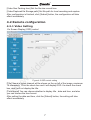
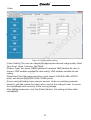
Preface:
n.
ru
Dear customer, thank you for choosing to purchase and use our IP camera
products. This series of IP monitoring product is the integrated IP network
camera which is researched for network video surveillance monitoring. The
series includes network bullet camera, network IR bullet camera, and network
dome camera, etc. High performance, monolithic SOC chip is utilized as media
processor which integrates video capture, compress and transmission. Standard
H.264 main profile encoding algorithm ensures more clear and smooth video
transmission. Embedded web server allows user to view real-time footage and
remote control via IE browser. This series of IP camera is well suited for home
and small business, as well as any situation which needs to apply remote network
transmission and remote network control. It's easy to install and operate.
io
Statement:
Intended Reader:
eo
-v
is
The content in this manual may be different from the product version you are
using. If you met any problem which can't be solved according to this manual,
please contact our tech-support or product supplier.
The content will be updated time to time. Our company reserves the right to
update without notice.
w
w
.v
id
This manual is mainly suitable for below kinds of engineer:
System planner
Onsite tech-support and maintenance personnel
Administrator for system installation, configuration and maintenance
Users for business operation on product functions
Terms in this manual:
w
IP Camera or IPC in this manual means network camera including network bullet
camera, network dome camera, network PT camera, and network IR camera, etc.
Click: Click with left button of mouse.
Double Click: Double click with left button of mouse.
Right click: Right click with right button of mouse.
The[ ]symbol indicates the windows name, menu name, or data table; such as
[Download Address].
®
Contents
1 Product Introduction........................................................................................2
1.1 BRIEF INTRODUCTION..............................................................................2
1.2 MAIN FEATURES........................................................................................2
ru
1.3 INSTALLATION STATEMENT......................................................................2
1.4 NETWORK IP CAMERA CONNECTION.....................................................3
n.
2 Log in...............................................................................................................3
io
3 Preview............................................................................................................5
4 System Setting................................................................................................6
is
4.1 LOCAL CONFIGURATION...........................................................................6
-v
4.2 REMOTE CONFIGURATION.......................................................................7
4.2.1 Video Setting.............................................................................................7
eo
4.2.2 Network Parameter..................................................................................10
4.2.3 Alarm setting............................................................................................19
id
4.2.4 System Information.................................................................................20
.v
4.2.5 Advanced setting.....................................................................................21
w
w
4.2.6 Serial port set up.....................................................................................24
w
5 Appendix.......................................................................................................25
1
®
1Product Introduction
1.1Brief Introduction
io
Power
n.
ru
This product is digitally monitored with a traditional analog camera and web video
service. Efficient Linux system, code in flash and small size that’s reliable and
steady.
Figure 1-1 Network IP Camera
Figure 1-2 Camera Cable Ports
eo
1.2 Main Features
Reset
-v
is
Network
w
w
w
.v
id
* The highest pixels for 30 W, 2M frame rate, real-time image
* Advanced video compression standard, high compression rate and flexible
operation
* 1/4’’CMOS sensor, fluid motion pics
* Automatic snapshot in all circumstance
* One key rescue system, dual stream and mobile phone live monitor
* Build-in WEB browser supports IE access
* Support multiple user simultaneously, multi-level management ensures high
system security.
* Support motion detection alarm (area, sensitivity configurable) and e-mail alert
function
* Support online system upgrade by remote control
* Automatic recovery function when the system temporarily loses internet
connection.
* Support PPPOE, DDNS, LAN, and Internet (ADSL, Cable Modem)
1.3 Installation Statement
During installation and operation, please pay attention to the following items:
1.When you received the package product, please check the equipment and
accessories according to the packing list inside the packing case.
2
®
eo
-v
is
io
n.
1.4 Network IP Camera Connection
ru
2.Before installation please carefully read this user manual.
3.When you install the IP camera, please close the power source of all the related
devices.
4.Check the voltage of the power source, to prevent device damage by
mismatching of voltage.
Installation environment: please do not use equipment under high humidity or
temperature. Make sure there is good ventilation and no blocking of air-vent.
Place it on a flat floor. Do not install it under violent vibration.
Figure 1-3 Device Connection of Network IP Camera
w
w
.v
id
Step one: Connect the IP Camera to your router or NVR using a network LAN
cable.
Step two: Connect the related power adapter to the IP Camera so that the
camera powers on.
Step three: Insert the Software CD into the PC computer that is connected to the
same local network as the IP Camera.
Note: It can also apply the way of IP Camera directly connecting with PC.
Note: When using IE browser to visit IP Camera, the IP of local PC should
be in the same segment with the IP of the IPC.
w
2 Log in
When using IE (Internet Explorer) to visit IP camera for the first time, you have to
set the security level for ActiveX controls.
Set security level: Open Internet Explorer, enter the IE Tools menu [Tools/Internet
Options/Security Settings/Custom Level…], Enable the “Active X Controls and
Plugins” and set the IP address of the IP Camera as “Trusted sites”.
3
-v
is
io
n.
ru
®
Figure 2-1 Security Level Setting
w
w
w
.v
id
eo
Install ActiveX and plugins: Type the network camera IP address in the IE browser
address bar, and press [Enter] to pop out dialog box of install ActiveX. Click [OK]
to install.
Log in and Preview: In Login screen, type in network camera username,
password, choosing language and click [OK] to enter the video preview interface.
Default:
IP Address: 192.168.0.100
UserName: admin Password: 111111
Figure 2-2 Safety Dialog box
Figure 2-3 Login Interface
4
®
-v
is
io
n.
ru
3 Preview
Figure 3-1 Real-time Preview Interface
w
w
w
.v
id
eo
In the real-time preview interface, the user can control the video channel switch,
record, snapshot, full screen preview, image process, image color, direction
configuration, and PTZ control.
[Video Channel] Double Click the channel number to open the video channel to
view image, right click and choose “Close” to close the video channel.
[Video Stream] Right Click the channel number to choose stream type(main
stream or sub stream)
[Record] Right click the image, choose “record” check to start record, remove
“record” check to stop record, the video is kept in file catalogue set by video
capture.
[Capture] Right click the image, choose “capture” to capture photos, the capture
photo is kept in catalog set by video capture.
[Full screen preview] Double click the image to full screen preview, double click
once again to go back to the original image size.
,
[Image process] The object of image processing includes brightness
contrast
, saturation
, use mouse to drag the slider to set these
items, as figure 3-2. The “Reset” button to recover the default configuration.
[Color and Direction Configuration] Image color can be black and white or color,
the image can be mirrored or reversed as figure 3-3 , NSTC or PAL also can be
set in this section.
[PTZ control] PTZ control to Upward, downward, left, right, the lens operation
includes vary magnification, vary focus, vary iris, etc. as shown in figure 3-4.
5
n.
ru
®
Figure 3-3
Color and direction control
io
Figure 3-2 I
mage parameter adjustment
Figure3-4
PTZ control
4 System Setting
-v
is
[System parameter setting] Click this button
to enter into system parameter
setting interface.
[Reboot device] Click this button
to reboot the device.
w
w
w
.v
id
eo
4.1 Local Configuration
Figure 4-1 Local Configuration
6
®
[Video files Packing time] Set the file size record time.
[Video/Captured file Storage path] Set file path for local recording and capture.
After configuration is finished, click [Submit] button, the configuration will take
effect immediately.
4.2 Remote configuration
4.2.1 Video Setting
w
w
.v
id
eo
-v
is
io
n.
ru
·On Screen Display (OSD) control
Figure 4-2 OSD control setting
w
[Title] Name of video channel will be shown on the up left of the image, maximum
16 characters. Click the check box and it will display OSD. Un-check the check
box, and it will not display the title.
[Time format] You can choose whether to display title , date and time, and also
you can choose the time format.
After setting the date and time, click the [Submit] button, the setting will take
effect immediately.
7
®
ru
·Video
eo
-v
is
io
n.
n
g
C
o
d
i
Figure 4-3 Video coding setting
w
w
w
.v
id
[Video Quality] The user can choose the appropriate desired image quality: Best,
Very Good, Good, Common, Not Good.
[Stream Type] Two types: CBR(Constant bit rate)and VBR(Variable bit rate) to
choose, CBR enables constant bit rate coding, VBR enables variable bit rate
coding.
[Resolution] Sets the image resolution: main stream VGA(640×480=307200
pixel), sub stream QVGA(320×240=76800 pixels).
[Frame rate] set coding frame rate per second. Under not satisfying network
situation, you can reduce the frame rate to control the coding bit rate, to ensure
the smoothness and continuity of the moving footage.
After setting parameters, click the [Submit] button, the setting will take effect
immediately.
8
®
-v
is
io
n.
ru
·Video shield
eo
Figure 4-4 Video shield setting
w
w
w
.v
id
[Video shield switch] Enable or disable the video shield functionality
[Shield area setting] User can set shield area by dragging mouse with left key
pressed, and cancel the shield box on the shield area by right clicking the mouse.
You can choose to shield the whole image, or only shield the part of the image. It
can mask up to four areas.
After setting parameters, click the [Submit] button, the setting will take effect
immediately.
9
®
4.2.2
Network Parameter
eo
-v
is
io
n.
ru
·Wired Setting
id
Figure 4-5 wired network setting
w
w
w
.v
[DHCP] If the router allows DHCP functionality, select DHCP. The IP Camera will
obtain IP address automatically from the router. If the router does not allow for
DHCP functionality, then the IP address must be obtained manually.
[IP Address] Set wired cable IP address of IP camera device.
[Subnet mask] Default: 255.255.255.0 (suggest user not to change this)
[Gateway] Set gateway IP of IPC, for example if IPC access public network
through router, the gateway IP need to be set as the router IP which has
accessed the public network.
[Physical address] MAC address of IP camera (suggest user not to change this)
[DNS address] If the user has a DDNS account, the DNS address needs to be
set as DNS address of the place where the device is belonging to.
After setting parameters, click the [Submit] button, the setting will take effect
immediately.
If it is applied in LAN, please make sure IP address does not conflict with
the IP address of other devices or computer in the same LAN.
10
®
eo
-v
is
io
n.
ru
·WIFI setting
Figure 4-6 IPC WIFI network setting
w
w
w
.v
id
[Whether to use WIFI] Select this check to open the wifi network function of IPC.
[Whether to use DHCP] If the router allows DHCP function, select this type, IP
camera will obtain IP address automatically from router.
[IP address] Set wireless IP address of IP camera.
[subnet mask] Set IP address of the current wireless gateway( router/AP), such
as 192.168.0.1
[Hotspot adding] After switch to Wifi setting, it will automatically search the
hotspot. When hotspot is searching; the name of the wireless router, signal
intensity, and the encryption will be listed on the screen. Click on “add hotspot”
or double click on an existing hotspot, open” wifi hotspot setting” dialog box as
below figure shown:
11
-v
is
io
n.
ru
®
Figure 4-7 Wifi Hotspot setting
w
w
w
.v
id
eo
If entered this screen by double clicking, hotspot will be assigned automatically;
if entered this screen by clicking “Add hotspot”, user has to type in hotspot,
corresponding encryption mode and password. Click [Connect], close the dialog
box, and connected or not will be list on the search results list.
If connected, “Connected” will appear after hotspot name; if not, please click
“Refresh” to refresh connection status or click this button to search device again.
After saving all parameters, click the [Exit] button, the setting will take effect
immediately.
Now pull out network cable, you can access the IP network camera via Wifi.
Note: WIFI setting only works to those types with WIFI function.
WIFI mode supported by IP Camera:
802.11b/g protocol (small power WiFi type)
802.11a/b/g/n protocol (large power WiFi type)
To use the wireless function of IP camera, a wireless router is needed such
as D-link.
12
®
eo
-v
is
io
n.
ru
·Listener port (LPRT)
Figure 4-8 LPRT setting
w
w
w
.v
id
[Web LPRT] The default port 80(port 80 is recommended), port for download
active X, if necessary to change, it should add port number behind IP address
during web visit http://ip:port/, such as http://192.168.0.100:/81 .
[Video LPRT] default 8000 (8000 is recommended).
[Mobile phone LPRT] default 9000 (9000 is recommended).
After setting all parameters, click the [submit] button, the setting will take effect
immediately.
Note: LPRT can be selectable during range of 1024~65535, can't be
repeated. Web LPRT can be 80.
13
®
eo
-v
is
io
n.
ru
·PPP0E
Figure 4-9 PPPOE parameters setting
w
w
w
.v
id
[Switch] Set to open or close PPPOE dial-up function
[User name] The ADSL dial-up account, obtain from internet service provider
[Password] Password of ADSL dial-up account, obtain from internet service
provider
After setting all parameters, click the [submit] button, the setting will take effect
immediately.
14
®
eo
-v
is
io
n.
ru
·UNPN (Auto port mapping)
Figure 4-10 UNPN port mapping setting
w
w
w
.v
id
[Switch] If in LAN it has server with UPNP functionality, enable this function, the
server will automatically forward the set port to public network.
[web mapping port] Set the web port which will be mapping to the server.
[digital mapping port] Set the digital port which will be mapping to the server.
[Mobile phone mapping port] Set the mobile phone port which will be mapping to
the server.
After setting all parameters, click the [submit] button, the setting will take effect
immediately.
Note: port mapping can be selectable between 1024~65535. It can't be
repeated.
15
®
eo
-v
is
io
n.
ru
·Email
Figure 4-11 Email parameters setting
w
w
w
.v
id
It is used to set Email address and related parameter of alarm email.
[SMTP Server] send email server address, different email service provider
provides different email server address, such as SMTP server of Google email
box: smtp.gmail.com
[Email receiving address] Email address to receive the email.
[Email sending address] Email address to send email.
[SMTP password] Log in password for the email box.
[Email title] The title of sending email.
[SMTP Port] Port of SMTP Server, different email server has different port, such
as Gmail email server port as 465, enables SSL.
After setting all parameters, click the [submit] button, the setting will take effect
immediately.
Common email server configurations:
Yahoo Email server:
SMTP Server: smtp.mail.yahoo.com
SMTP User name:[email protected]
SMTP Port: 465
SSL: Enabled
16
®
eo
-v
is
io
n.
ru
·FTP
Figure 4-12 FTP parameters setting
w
w
w
.v
id
FTP services will send the alarm triggered recording file or captured photo via
FTP to certain FTP server.
[FTP server] IP address or HTTP network address of FTP server.
[FTP port] Port of FTP server, default port is 21.
[User] User name of the FTP Server.
[Password] Password of the FTP Server.
After setting all parameters, click the [Submit] button, the setting will take effect
immediately.
17
®
eo
-v
is
io
n.
ru
·DDNS
w
w
w
.v
id
Figure 4-13 DDNS parameter setting
Dynamic DNS setting, through this setting it can bond device with a fixed domain,
no matter how public network IP varies, it can visit the device via this domain.
User can register a DDNS account on website of 3322.org.
[Switch] Setting open or close DDNS function.
[Server] 3322.org or dynDDNS.org selectable.
[DNS] The device domain which is set by user, such as zmodo.3322.org.
[User] The user name which you registered on DDNS server.
[Password] The password which you registered on DDNS server.
After setting all parameters, click the [Submit] button, the setting will take effect
immediately.
18
®
eo
-v
is
io
n.
ru
4.2.3 Alarm setting
Figure 4-14 Motion detection setting
w
w
w
.v
id
[Protection time setting] Set the protection time of motion detection. It can set
detail time period of everyday, up to four time periods. Select the time and click
the [Save] button, then the time period selection will take into force.
[Motion detection switch] Set open or close of motion detection,enable this switch
to edit the motion detection area.
[Motion detection setting] After enable motion detection switch, the setting
interface will appear grid line. User only needs to click the little cube on the image
to set the motion detection area. Right click the little cube to cancel related area
detection.
[Alarm action mode] Set linkage output format after triggered alarm. Sending
email is sending motion detection alarm information via email to user, the detailed
Email parameter see chapter 4.2.2. There will be no Email alert if user didn't set
email parameter previously.
[Sensitivity] The sensitivity of motion detection includes three levels: High, Little
high, Mid, and Low.
[Output delay] Set delay time of alarm linkage, time range is limited between
0~30.
After setting all parameters, click the [submit] button, the setting will take effect
immediately.
19
®
-v
is
io
n.
ru
4.2.4 System Information
w
w
w
.v
id
eo
Figure 4-15 Version Information
Figure 4-16 System time setting
20
®
[Version] Display device name, system version, video/audio channel number,
sensor/alarm input/output, local storage.
[Time Setting Switch] Enable this switch to manually set the system date and
time; disable this switch then the system date and time will be synchronized with
local PC only to check the status and can't be configured to disable this switch.
After setting all parameters, click the [Sync time] button, the setting will take effect
immediately.
ru
4.2.5 Advanced setting
w
w
.v
id
eo
-v
is
io
n.
·User management
Figure 4-17 User management interface
w
Each IP camera can be set up to have up to 15 users. Admin is the system
default super user and cannot be deleted, but the admin password can be
changed. User's authority is as following:
Super-User authority: operate and set all the function and parameter of IP camera
Common user authority: The common user is allowed to view video, adjust their
password and delete their own account. Common users are not granted any
additional authorities.
Note: the default user after leaving factory is admin, the password is 111111.
Both user names and passwords are case sensitive.
21
®
eo
-v
is
io
n.
ru
·Periodic maintenance
Figure 4-18 Periodic maintenance setting
w
w
w
.v
id
[Periodic Maintaining] Choose to open periodic maintenance and set
maintenance time, detailed maintenance time on everyday can be configured.
After setting all parameters, click the [submit]
[Restore factory setting] Click this button to recover all the setting of the device
back to factory setting.
[Reboot Device] Click this button to reboot the device.
Note: Periodic maintenance and reboot the device will need to wait for 30
seconds to restore video surveillance.
22
®
eo
-v
is
io
n.
ru
·Software update
Figure 4-19 Software Update
w
w
w
.v
id
[Update File] Click “.” to browse for the correct update file (application file: RELAPP, Please not change the file name), click “Update”. During the update, it
will display update information. After update finished, IP Camera will reboot
automatically. Log into the device once again and enter the software update
interface to check whether the system version has been updated.
Note: During updating, please do not disconnect the camera from its power
source or from the internet connection.
23
®
eo
-v
is
io
n.
ru
4.2.6 Serial port set up
Figure 4-20 Serial port setting
w
w
w
.v
id
When IP camera has external RS485 communication or control device (such as
a PTZ controller) the user needs to set the RS 485 parameter according to the
setting of these external devices. The channel, address, speed, protocol, and
bit rate need to be set accordingly. Only all these are set correctly, the external
communication device can be used to control the camera.
[Channel] Select the channel of device.
[PTZ protocol] The communication protocol setting, the user can choose Pelco_D
or Pelco_P. The protocol is the same as that of the PTZ device.
[PTZ speed] Ranging from 1~64
[PTZ address] Ranging from 1~255
[Data Format] The setting of RS485 communication data format includes bite
rate, date position, check digit and stop bit.
After setting all parameters, click the [submit] button, the setting will take effect
immediately.
24