1
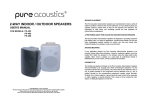
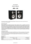
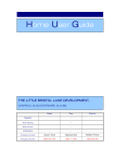
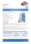
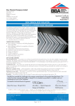
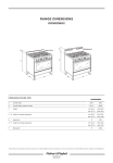
APPROVAL INSPECTION TESTING CERTIFICATION Munster Joinery Ltd Ballydesmond County Cork Ireland Tel: 00 353 64 77 51151 Fax: 00 353 64 77 51311 TECHNICAL APPROVALS FOR CONSTRUCTION Agrément Certificate 02/3957 e-mail: [email protected] website: www.munsterjoinery.ie Product Sheet 1 MUNSTER JOINERY CAVITY CLOSER SYSTEMS MUNSTER JOINERY CAVITY CLOSER AND SUBFRAME SYSTEM This Agrément Certificate Product Sheet (1) relates to the Munster Joinery Cavity Closer and Subframe System, for use as a cavity closer and to form an opening in masonry cavity walls. (1) Hereinafter referred to as ‘Certificate’. CERTIFICATION INCLUDES: • factors relating to compliance with Building Regulations where applicable • factors relating to additional non-regulatory information where applicable • independently verified technical specification • assessment criteria and technical investigations • design considerations • installation guidance • regular surveillance of production • formal three-yearly review. KEY FACTORS ASSESSED Hygrothermal behaviour — the cavity closers meet and exceed the minimum thermal resistance path of 0.45 m2·K·W–1 as required by the Accredited Construction Details (version 1.0). Default -values (Psi) in BRE Information Paper IP 1/06 may, therefore, be used for jamb and sill junctions in SAP or SBEM (see section 6). Water resistance — the system is effective as a damp-proof barrier and, when used in a suitable wall construction, will resist the passage of water into the interior of the building in flush reveal installations (see section 7). Structural stability — in terms of wind loading resistance, the system can be used in all areas of the UK. The system must not be used to support loads from the masonry (see section 8). Behaviour in relation to fire — the installed system will not contribute significantly to the growth of a fire. The system does not constitute a cavity barrier (see section 9). Durability — the cavity closer profiles, protected within the cavity, will continue to function for the normal expected life of a building; visible components will have an expected life in excess of 35 years (see section 12). The BBA has awarded this Certificate to the company named above for the system described herein. This system has been assessed by the BBA as being fit for its intended use provided it is installed, used and maintained as set out in this Certificate. On behalf of the British Board of Agrément Date of First issue: 6 December 2013 John Albon — Head of Approvals Claire Curtis-Thomas Originally certificated on 23 September 2002 Energy and Ventilation Chief Executive The BBA is a UKAS accredited certification body — Number 113. The schedule of the current scope of accreditation for product certification is available in pdf format via the UKAS link on the BBA website at www.bbacerts.co.uk Readers are advised to check the validity and latest issue number of this Agrément Certificate by either referring to the BBA website or contacting the BBA direct. British Board of Agrément Bucknalls Lane Watford Herts WD25 9BA ©2013 Page 1 of 11 tel: 01923 665300 fax: 01923 665301 e-mail: [email protected] website: www.bbacerts.co.uk Regulations In the opinion of the BBA, the Munster Joinery Cavity Closer and Subframe System, if installed, used and maintained in accordance with this Certificate, will satisfy or contribute to satisfying the relevant requirements of the following Building Regulations (the presence of a UK map indicates that the subject is related to the Building Regulations in the region or regions of the UK depicted): The Building Regulations 2010 (England and Wales) (as amended) Requirement: C2(b) Resistance to moisture Comment: The system has adequate resistance to the ingress of rain and wind-driven spray and so can contribute towards the wall satisfying this Requirement. See section 7 of this Certificate. Requirement: C2(c) Resistance to moisture Comment: The system will not constitute a significant condensation risk and so can contribute towards the wall satisfying this Requirement. See sections 6.2 and 6.3 of this Certificate. Requirement: L1(a)(i) Conservation of fuel and power Comment: Regulation: 7 Materials and workmanship Comment: Regulation: 26 CO2 emission rates for new buildings The system can contribute to minimising heat loss at jambs and sills. See section 6.1 of this Certificate. The system is acceptable. See section 12 and the Installation part of this Certificate. The system can contribute to minimising heat loss at jambs and sills. See sections 6.1 and 6.3 of this Certificate. Comment: The Building (Scotland) Regulations 2004 (as amended) Regulation: 8(1) Regulation: Standard: 9 3.10 3.15 6.1(b) 6.2 7.1(a)(b) Statement of sustainability The system can contribute to satisfying the relevant requirements of Regulation 9, Standards 1 to 6, and therefore will contribute to a construction meeting a bronze level of sustainability as defined in this Standard. In addition, the system can contribute to a construction meeting a higher level of sustainability as defined in this Standard, with reference to clauses 7.1.4(1)(2) [Aspects 1(1)(2) and 2(1)], 7.1.6(1)(2) [Aspects 1(1)(2) and 2(1)] and 7.1.7(1)(2) [Aspect 1(1)(2)]. See section 6 of this Certificate. Comment: Regulation: Carbon dioxide emissions Building insulation envelope The system can contribute to minimising heat loss at jambs and sills, with reference to clauses 6.2.3(1), 6.2.4(1)(2) and 6.2.5(2). See section 6.1 of this Certificate. Comment: Standard: Condensation The system will not constitute a significant condensation risk and so can contribute towards the wall satisfying this Standard, with reference to clauses 3.15.1(1)(2), 3.15.4(1)(2) and 3.15.5(1)(2). See sections 6.2 and 6.3 of this Certificate. Comment: Standard: Standard: Building standards applicable to construction Precipitation The system has adequate resistance to the ingress of rain and wind-driven spray and so can contribute towards the wall satisfying this Standard, with reference to clauses 3.10.1(1)(2) and 3.10.3(1)(2). See section 7 of this Certificate. Comment: Standard: Durability, workmanship and fitness of materials The system can contribute to a construction satisfying this Regulation. See section 12 and the Installation part of this Certificate. Comment: 12 Building standards applicable to conversions All comments given for this system under Regulation 9, Standards 1 to 6, also apply to this Regulation, with reference to clause 0.12.1(1)(2) and Schedule 6(1)(2). Comment: (1) Technical Handbook (Domestic). (2) Technical Handbook (Non-Domestic). The Building Regulations (Northern Ireland) 2012 Regulation: 23 Fitness of materials and workmanship Comment: Regulation: 28 Resistance to moisture and weather The system is acceptable. See section 12 and the Installation part of this Certificate. The system has adequate resistance to the ingress of rain and wind-driven spray and so can contribute towards the wall satisfying this Regulation. See section 7 of this Certificate. Comment: Regulation: 29 Regulation: Regulation: Comment: Condensation The system will not constitute a significant condensation risk and so can contribute towards the wall satisfying this Regulation. See section 6.3 of this Certificate. Comment: 39(a)(i) 40(2) Conservation measures Target carbon dioxide emission rate The system can contribute to minimising heat loss at jambs and sills. See section 6.1 of this Certificate. Page 2 of 11 Construction (Design and Management) Regulations 2007 Construction (Design and Management) Regulations (Northern Ireland) 2007 In the opinion of the BBA, there is no information in this Certificate which relates to the obligations of the client, CDM co-ordinator, designer and contractors under these Regulations. Additional Information NHBC Standards 2013 NHBC accepts the use of the Munster Joinery Cavity Closer and Subframe System, provided it is installed, used and maintained in accordance with this Certificate, in relation to NHBC Standards, Chapter 6.1 External masonry walls. Technical Specification 1 Description 1.1 The Munster Joinery Cavity Closer and Subframe System (see Figure 1) is an insulated unplasticised polyvinyl chloride (PVC-U) cavity closer and window sub-frame, used to form an opening in masonry cavity walls during construction. It is made from extruded profiles fitted with polyurethane foam core (PUR, estimated thermal conductivity D 0.041 W·m–1·K–1) insulation in accordance with BS EN 13165 : 2012. The profiles are formed into a U-shape template with welded corners at the sill and a temporary timber batten brace (typical 65 mm by 40 mm), to be removed prior to the installation of the window frame. Alternatively, a head vent profile is mechanically joined to form the head section. 1.2 The cavity frame components and accessories are listed in Table 1 and shown in Figure 1. Table 1 List of components Manufacturer’s designation Components Application CC100.12 Cavity closer/subframe Jamb and sill, 100 mm cavity CCH01 Vented head Head section profile CCLB Adaptor Jamb section CCHB Bead Head section CCB Bead Head and jamb sections Skyline Tie Cavity closer tie HL01 Fixing cleat Fixed to windows at head LUG1 Fixing cleat Fixed to windows at sill — Bracket Head support bracket — Stainless steel screws (4.8 diameter 95 mm) For fixing overhead ventilator to jambs — Stainless steel screws (3.9 diameter 19 mm) Brackets fixing screws — Carbon steel screws (3.19 diameter 19 mm) Fixing cleats fixing screws Page 3 of 11 Figure 1 Components (dimensions in mm) 100 CC100.12 CCH01 CCB CCHB CCLB LUG1 HL01 Skyline tie 1.3 The main PVC-U profile incorporates a box section to fit into the wall cavity. 1.4 Drainage holes of 3 mm diameter are provided at either end of the sill piece of the cavity closer in accordance with the Munster Joinery Cavity Closer/Subframe Fabrication and Installation Manual. 1.5 A gasket, made from TPE, is co-extruded onto the bead and adaptor profiles. 1.6 The cavity closer profiles are produced by conventional extrusion techniques from reground PVC-U material. The head, bead and adaptor profiles are extruded from virgin PVC-U and are available in white PVC-U or woodgrain finish (mahogany or golden oak foiled). 1.7 Polypropylene ties, manufactured by standard injection-moulding techniques, are used to build the cavity closer into the surrounding mortar joints (see Figures 1 and 3). Page 4 of 11 Figure 2 Typical head with window detail vented head bead bead Figure 3 Typical jamb with window detail silicone sealant bead adaptor silicone sealant silicone sealant outer leaf inner leaf 30 mm Page 5 of 11 Figure 4 Typical sill with window detail silicone sealant silicone sealant silicone sealant 30 mm 2 Manufacture 2.1 The cavity closer unplasticised polyvinyl chloride (PVC-U) profiles are produced by conventional extrusion techniques. The insulation is blown in the cavity closer profiles at the factory. 2.2 As part of the assessment and ongoing surveillance of product quality, the BBA has: • • • • • • agreed with the manufacturer the quality control procedures and product testing to be undertaken assessed and agreed the quality control operated over batches of incoming materials monitored the production process and verified that it is in accordance with the documented process evaluated the process for management of nonconformities checked that equipment has been properly tested and calibrated undertaken to carry out the above measures on a regular basis through a surveillance process, to verify that the specifications and quality control operated by the manufacturer are being maintained. 2.3 The management system of Munster Joinery Ltd has been assessed and registered as meeting the requirements of BS EN ISO 9001 : 2008 by NSAI (Certificate 19.1077). 3 Delivery and site handling 3.1 Assembled subframes are labelled with product identification and the BBA identification mark incorporating the number of this Certificate. They are dispatched along with the requisite number of ties, any additional ancillary items and installation instructions. 3.2 The pre-assembled subframes are stacked vertically and delivered as individual items, taking care to avoid distortion in transit. They should be protected from vehicular and pedestrian traffic and stored under cover in a clean area, on edge, and suitably supported to avoid distortion or damage. Assessment and Technical Investigations The following is a summary of the assessment and technical investigations carried out on the Munster Joinery Cavity Closer and Subframe System. Design Considerations 4 General 4.1 The Munster Joinery Cavity Closer and Subframe System is suitable for use in masonry walls with nominal cavity widths of 100 mm and with PVC-U window frames. 4.2 The system can be used as a template to form an opening around which a wall can be constructed, and to establish the cavity width during construction. 4.3 The system provides a damp-proof barrier between inner and outer wall leaves at the point of closure, acts as a cavity closer without forming a thermal bridge, and avoids the need for cutting bricks and blocks. The window is fitted after completion of the masonry. Page 6 of 11 4.4 Masonry walls into which the system is incorporated must be constructed in accordance with one or more of the following technical specifications: • BS EN 1996-1-1 : 2005, BS EN 1996-1-2 : 2005, BS EN 1996-2 : 2006, BS EN 1996-3 : 2006 and the relevant National Annexes • the national Building Regulations: England and Wales – Approved Document A1/2, Section 1C Scotland – Mandatory Standard 1.1(1)(2), Small Buildings Guide (1) Technical Handbook (Domestic). (2) Technical Handbook (Non-Domestic). Northern Ireland – Technical Booklet D. 4.5 Windows are fitted into the subframe from the inside of the building. 4.6 Subframes are manufactured to suit the exact brickwork opening. A 6 mm clearance per side is allowed between the subframe and window, in accordance with the Munster Joinery Cavity Closer/Subframe Fabrication and Installation Manual. 4.7 The maximum subframe cavity closer size is 2400 mm by 1300 mm. 5 Practicability of installation The system is designed to be installed by a competent general builder, or a contractor, experienced with this type of system. 6 Hygrothermal behaviour 6.1 The cavity closer can contribute to maintaining continuity of thermal insulation at jambs and sills in wall openings. The path of minimum thermal resistance through the closer calculated to BRE Information Paper IP 8/08 is at least 0.45 m2·K·W–1 when used in jambs and sills with the window frame setback 30 mm or more into the wall cavity. Example junction details shown in Figures 3 and 4 are acceptable and the corresponding -values (Psi) in BRE Information Paper IP 1/06, Table 3, may be used in carbon emission calculations in Scotland and Northern Ireland. Attention must be given to the correct setback in order to ensure compliance with these requirements. Detailed guidance on limiting heat loss and air filtration can be found in: England and Wales — Approved Documents to Part L and, for new thermal elements to existing buildings, Accredited Construction Details (version 1.0). See also SAP 2009 Appendix K and the iSBEM User Manual for new-build Scotland — Accredited Construction Details (Scotland) Northern Ireland — Accredited Construction Details (version 1.0). 6.2 Jambs and sills incorporating the system in accordance with section 6.1 will adequately limit the risk of local surface condensation. 6.3 Under normal domestic conditions, the level of interstitial condensation associated with the system will be low and the risk of any resultant damage minimal. 6.4 The junctions between the wall and the front and back of the window frame must be effectively sealed. 7 Water resistance 7.1 The system is effective as a vertical damp-proof barrier at jambs of window openings in masonry constructions, where a brick/block closer and damp-proof course (dpc) detail would normally be used. The system is also effective as a horizontal damp-proof barrier at the sill. 7.2 Installations with a flush (in-line) wall opening with a minimum window setback of 30 mm (see Figures 3 and 4) are suitable for use in the exposure zones 1 (sheltered), 2 (moderate) and 3 (severe) as depicted in the map contained in section 3.1 of BRE Report BR 262 : 2002. The subframe may also be considered suitable for use in other areas where a conventional return brick/block closer detail with dpc has been found to provide adequate resistance to the penetration of wind-driven rain. 8 Structural stability 8.1 The system is non-loadbearing and must not be used to support loads from the masonry. Lintels are required above window openings. 8.2 The system will not have an adverse effect on the structural stability of brickwork or blockwork walls constructed in the conventional manner in accordance with normal good practice as defined in the Standards listed in section 4.4 of this Certificate. Use of the system does not obviate the need for conventional wall ties around the openings. 8.3 A window fitted correctly into a cavity frame, using beads at the jambs and bead and conventional fixing lugs at the head and sill, will satisfactorily transfer to the structure wind loads likely to be encountered in the UK. In terms of wind loading resistance, the cavity frame can be used in all areas of the UK. Page 7 of 11 9 Behaviour in relation to fire 9.1 The installed system will not contribute significantly to the growth of a fire. 9.2 The system does not constitute a cavity barrier against the penetration of smoke and flame in the context of the Building Regulations. 9.3 The use of the system is not prevented in England and Wales where, generally, cavity barriers are not required around openings in masonry wall construction. 9.4 In Scotland and Northern Ireland, the system is only suitable for use in conjunction with a cavity barrier meeting the performance requirements defined in: Scotland — Mandatory Standard 2.4, clause 2.4.1(1)(2) and Annex 2.B(1) or 2.D(2) (1) Technical Handbook (Domestic). (2) Technical Handbook (Non-Domestic). Northern Ireland — Technical Booklet E, Paragraph 4.38. 9.5 The use of the system does not preclude the need to provide suitable fire protection to steel lintels where this is necessary to satisfy the Building Regulations. 10 Security against intrusion Removal of a window from the cavity closer/frame acceptor from outside is extremely difficult as the windows are secured by internally-fitted rebate upstand profiles (beads) at the head and jambs. When correctly fitted, the rebate upstands lock the window frame in position against a flange (part of the adaptor which fits into the cavity closer/frame acceptor body profile). 11 Maintenance To ensure the maximum weathertightness, the seal between window frames and masonry must be checked regularly and repairs or renewal carried out promptly. 12 Durability The system is durable when installed in accordance with this Certificate and will not suffer significant degradation when protected within the cavity. The system will continue to function for the normal expected life of a building. Visible components will have an expected life in excess of 35 years. 13 Reuse and recyclability The PVC-U profiles of the system can be recycled. Installation 14 General 14.1 Installation of the Munster Joinery Cavity Closer and Subframe System must be carried out in accordance with the manufacturer’s instructions. 14.2 A cavity barrier may be required (see section 9.2). 14.3 Reference should be made to the typical installation details shown in Figures 2, 3 and 4; these Figures, however, are for information only and do not form part of this assessment. 14.4 At the build-in stage, it must be ensured that the subframe remains plumb, level, square and with parallel sides. 14.5 The junction between the wall and the front and back of the window frame must be effectively sealed. 15 Procedure 15.1 The assembled welded subframe, including cross brace or vented head at the head section, is ready for building into the construction of cavity walls using traditional building methods. 15.2 The cavity wall is built to the sill level, ensuring that the course work is level and flat, and that all excess mortar is removed. 15.3 The subframe is positioned in the cavity, ensuring that it is facing the correct way, and temporary timber supports are attached to the closer, if required. The closer frame is aligned with a spirit level, and the timber supports are secured so that they are rigid and keep the frame square and plumb. The course work is built up by one course and butted to one side of the subframe. 15.4 The position of the subframe is checked and the course work on the opposite side of the subframe is built up by one level. 15.5 Ties are inserted into the channel of the subframe jambs, rotated through 90º and built into the mortar bed joints. These ties should be fitted after the first brick course and then at every five to six brick intervals. The ties should be inserted alternately, tying the subframe into both inner and outer courses, ensuring that the subframe is tight against the outer brick. A minimum of three ties per vertical member is required. Page 8 of 11 15.6 When the masonry reaches head level, the head batten, if used, is removed and a lintel, with associated dpc, is fitted across the masonry just clear of the top of the subframe. Where the vented head is used, it is tied to the building structure using fixing cleats. The number of fixing cleats required depends on the width of the opening. Typically, for a window 2000 mm wide, two cleats are required. The wall construction is continued to complete the aperture. 15.7 In all installations, the top brick course should be arranged to ensure that, when bedded in, the lintel does not exert a load on the window frame/subframe. 15.8 The subframe is cleaned to ensure that it is free from mortar. The brickwork must be allowed to set before attempting to fit the window. 15.9 The fitting of windows to the former must be carried out in accordance with the Munster Joinery Cavity Closer Subframe Fabrication and Installation Manual. Finishing 15.10 An effective sealant is applied around the perimeter of the window internally, prior to applying internal finishes. 15.11 In locations where the plaster may be subject to repeated impact (eg at door reveals from door slamming), it is recommended that wet plaster should be reinforced by hessian scrim or, preferably, replaced by dry lining. 15.12 Finishing trims, where required, are fitted after completion of the window installation. 15.13 The window is weatherproofed externally, using a suitable low modulus silicone sealant. Technical Investigations 16 Tests 16.1 Confirmatory tests were carried out on PVC-U extrusions made from virgin material, to determine: • shrinkage on heating • changes on heating. 16.2 Tests were carried out on a combined subframe and PVC-U window, installed in a test rig, to determine: • air permeability • watertightness • effect of cyclic wind loads to ±1250 Pa • effect of temperature variation (–5°C to 55°C) • safety test, wind loading using increased pressure of ±2300 Pa and reduced pressure of –3000 Pa(1). (1) The test was performed at reduced temperature to ensure that the contraction of the window under such conditions would not render the system unsafe. 17 Investigations 17.1 An assessment was made of existing data to determine: PVC-U extrusions • • • • • • Vicat softening temperature shrinkage on heating verification of gelation by heating ash content induction time of dehydrochlorination gelation by immersion in a solvent Foiled extrusions • adhesive bond strength • cross cut adhesion • appearance after ageing. 17.2 An assessment was made of: • heat loss and condensation risk in accordance with the Accredited Construction Details (version 1.0) (England and Wales and Northern Ireland) and the Accredited Construction Details (Scotland) • weather resistance of the system when installed in accordance with the manufacturer’s instructions • the practicability of the installation • fire resistance and structural stability of walls incorporating the cavity closer subframe • durability of the components used in the construction of the system. 17.3 The manufacturing process was evaluated, including methods for quality control, and details were obtained of the quality and composition of the materials used. Page 9 of 11 Bibliography BS EN 1996-1-1 : 2005 Eurocode 6 — Design of masonry structures — General rules for reinforced and unreinforced masonry structures NA to BS EN 1996-1-1 : 2005 UK National Annex to Eurocode 6 — Design of masonry structures — General rules for reinforced and unreinforced masonry structures BS EN 1996-1-2 : 2005 Eurocode 6 — Design of masonry structures — General rules — Structural fire design NA to BS EN 1996-1-2 : 2005 UK National Annex to Eurocode 6 — Design of masonry structures — General rules BS EN 1996-2 : 2006 Eurocode 6 — Design of masonry structures — Design considerations, selection of materials and execution of masonry NA to BS EN 1996-2 : 2006 UK National Annex to Eurocode 6 — Design of masonry structures — Design considerations, selection of materials and execution of masonry BS EN 1996-3 : 2006 Eurocode 6 — Design of masonry structures — Simplified calculation methods for unreinforced masonry structures NA to BS EN 1996-3 : 2006 UK National Annex to Eurocode 6 — Design of masonry structures — Simplified calculation methods for unreinforced masonry structures BS EN 13165 : 2012 Thermal insulation products for buildings — Factory made rigid polyurethane foam (PU) products — Specification BS EN ISO 9001 : 2008 Quality management systems — Requirements Paper IP 1/06 Assessing the effects of thermal bridging at junctions and around openings Paper IP 8/08 Determining the minimum thermal resistance of cavity closers BRE Report BR 262 : 2002 Thermal insulation : avoiding risks Page 10 of 11 Conditions of Certification 18 Conditions 18.1 This Certificate: • relates only to the product/system that is named and described on the front page • is issued only to the company, firm, organisation or person named on the front page — no other company, firm, organisation or person may hold or claim that this Certificate has been issued to them • is valid only within the UK • has to be read, considered and used as a whole document — it may be misleading and will be incomplete to be selective • is copyright of the BBA • is subject to English Law. 18.2 Publications, documents, specifications, legislation, regulations, standards and the like referenced in this Certificate are those that were current and/or deemed relevant by the BBA at the date of issue or reissue of this Certificate. 18.3 This Certificate will remain valid for an unlimited period provided that the product/system and its manufacture and/or fabrication, including all related and relevant parts and processes thereof: • are maintained at or above the levels which have been assessed and found to be satisfactory by the BBA • continue to be checked as and when deemed appropriate by the BBA under arrangements that it will determine • are reviewed by the BBA as and when it considers appropriate. 18.4 The BBA has used due skill, care and diligence in preparing this Certificate, but no warranty is provided. 18.5 In issuing this Certificate, the BBA is not responsible and is excluded from any liability to any company, firm, organisation or person, for any matters arising directly or indirectly from: • the presence or absence of any patent, intellectual property or similar rights subsisting in the product/system or any other product/system • the right of the Certificate holder to manufacture, supply, install, maintain or market the product/system • actual installations of the product/system, including their nature, design, methods, performance, workmanship and maintenance • any works and constructions in which the product/system is installed, including their nature, design, methods, performance, workmanship and maintenance • any loss or damage, including personal injury, howsoever caused by the product/system, including its manufacture, supply, installation, use, maintenance and removal • any claims by the manufacturer relating to CE marking. 18.6 Any information relating to the manufacture, supply, installation, use, maintenance and removal of this product/ system which is contained or referred to in this Certificate is the minimum required to be met when the product/system is manufactured, supplied, installed, used, maintained and removed. It does not purport in any way to restate the requirements of the Health and Safety at Work etc. Act 1974, or of any other statutory, common law or other duty which may exist at the date of issue or reissue of this Certificate; nor is conformity with such information to be taken as satisfying the requirements of the 1974 Act or of any statutory, common law or other duty of care. British Board of Agrément Bucknalls Lane Watford Herts WD25 9BA ©2013 Page 11 of 11 tel: 01923 665300 fax: 01923 665301 e-mail: [email protected] website: www.bbacerts.co.uk